Whenever one routine calls another, certain information about the calling routine must be saved so that, upon return, execution within the calling routine can be resumed where it left off. The information from the calling routine is saved in a structure of data known as a “frame” and is “pushed” onto what is referred to as a “stack.”
During system crash dump analysis, stacks play a vital role. It is here where we find out who called whom and with what arguments. Although we can use adb’s $c command to get a C stack traceback, we will also want to be able to examine stacks by hand on some occasions. In order to be able to do that, we need to understand what a stack looks like. Before we talk about a specific architecture’s stack format, let’s talk about stacks in very generic terms.
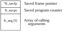
The diagram below illustrates a simplified view of a stack frame. The only data this sample frame holds is a pointer to the previous frame, the program counter from the previous routine, and the arguments that were passed to the new routine.
This simple frame layout is actually that used by the sun2 hardware architecture and probably other vendors’ system architectures as well.
When one routine calls another routine, the three pieces of information diagrammed above will need to be loaded into a new frame that is placed or “pushed” onto the current stack. How this data gets moved onto the stack is implementation-specific. Soon, we will see how this is done on SPARC systems. For now, we’ll just trust that it gets done for us.
As shown in the previous figure, the address of the caller’s frame is saved in fr_savfp of the new frame. This provides us with a way of returning to the caller’s frame.
The address, or program counter, of the instruction that caused us to jump into the new routine is stored in fr_savpc. This is used when it’s time for us to return to the calling routine.
Finally, the arguments or parameters passed to the new routine are stored in the frame starting at fr_arg.
Now, keeping this as generic as possible, let’s watch our stack grow as the result of a call to a new routine.
Here is a little program that calls a little routine, passing it three parameters. The little routine, fred(), actually does nothing at all.
main ()
{
  fred (1, 2, 3);
}

int fred (a, b, c)
int a, b, c;
{}
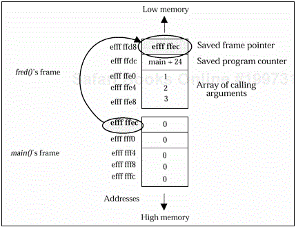
When we start running main(), an initial frame will be put on the stack. This is taken care of for us by the system. For now, we will demonstrate this initial frame as being filled with nulls or zeros. When we call fred(), a new frame will be put or “pushed” onto the stack for us. While we are actually in fred(), our stack will hold two frames, as shown in the next figure.
When we are done executing fred() and need to return to main(), we will use the saved PC, the address of main+24 in this example, as our reference of where to return within the main routine. This is in the current frame in fr_savpc. In many machines, this is the address of the instruction following the call to fred(). On SPARC, this is the actual address of the calling instruction, usually some sort of jump to subroutine or call instruction. Since we’ve already executed the instruction at main+24, we will not be executing the instruction referenced in the saved PC, but instead we will be using it as a reference for where to resume within the main routine.
As we return to main(), the original frame becomes our current frame. This is known as “popping” the stack. The area of memory that was used to store the stack frame we were using while in fred() is now considered free. If we were to call fred() a second time from main(), a brand-new frame would be constructed and pushed onto the stack.
Looking at the figure above, what may cause some confusion for you at this point is the direction in which the stack grows. Instead of starting at a low memory address and growing towards high memory, the stack starts in high memory and works its way down towards low memory.
Okay, that’s the general concept. Now let’s talk about SPARC frames in detail.
If you’ve been poking around in /usr/include, you may have already discovered the header files that describe your system’s stack and the frames on the stack. These files are in different locations on Solaris 1 and Solaris 2 systems.
On Solaris 1, you will want to look in the /usr/include subdirectory for your system’s architecture; sun2, sun3, sun3x, sun4, sun4c, or sun4m. Within that directory, you’ll find the stack described in asm_linkage.h.
asm_linkage.h diagrams a stack and defines several stack-related functions and assembly language macros. However, asm_linkage.h does not describe the contents of a stack in any real detail. It just shows a nice diagram. To get the details of what a frame on the stack looks like, we have to look at frame.h which can be found in the same directory as asm_linkage.h.
Since the stack basically looks the same between the BSD-based SunOS and the SVR4-based Solaris 2, we will use a Solaris 2 system throughout the rest of this chapter.
On Solaris 2 systems, the stack is diagrammed in /usr/include/sys/stack.h; however, again, the actual definition of the frame structure is in /usr/include/sys/frame.h. First, let’s look at a trimmed-down picture of /usr/include/sys/stack.h.
Example 17-1. Excerpt from /usr/include/sys/stack.h
/*
 * A stack frame looks like:
 *
 * %fp->|                               |
 *      |-------------------------------|
 *      |  Locals, temps, saved floats  |
 *      |-------------------------------|
 *      |  outgoing parameters past 6   |
 *      |-------------------------------|-
 *      |  6 words for callee to dump   | |
 *      |  register arguments           | |
 *      |-------------------------------|  > minimum stack frame
 *      |  One word struct-ret address  | |
 *      |-------------------------------| |
 *      |  16 words to save IN and      | |
 * %sp->|  LOCAL register on overflow   | |
 *      |-------------------------------|-/
 */
Here is the frame structure as described in this partial view of /usr/include/sys/frame.h on a SPARCstation 20 system running Solaris 2.3.
/*
 * Definition of the sparc stack frame (when it is pushed on the stack).
 */
struct frame {
     int     fr_local[8];           /* saved locals */
     int     fr_arg[6];             /* saved arguments [0 - 5] */
     struct frame    *fr_savfp;     /* saved frame pointer */
     int     fr_savpc;              /* saved program counter */
     char    *fr_stret;             /* struct return addr */
     int     fr_argd[6];            /* arg dump area */
     int     fr_argx[1];            /* array of args past the sixth */
};
Let’s talk about the SPARC frame structure in detail.
The first eight integers in a frame, fr_local [0] through fr_local [7], are the contents of the local registers %l0 through %l7. These are full 32-bit words. Local registers are used locally within a routine only and are not used to pass information to another routine.
The next six integers, fr_arg [0] through fr_arg [5], contain the first six arguments a routine or procedure receives when being called. If more than six arguments were sent, we will find the remainder of them elsewhere on the stack.
The next word in the frame structure contains the address of the previous frame. In other words, this is a pointer to another frame structure. This corresponds to register %i6,which is the old stack pointer (%o6) belonging to the calling routine.
The next word, fr_savpc, contains the PC or program counter of the last instruction executed by the calling routine. When you look at this, you will usually find a call or jump instruction. When we “pop” the stack to return to the calling routine, this PC is used as the reference for where execution is to continue.
The next word, fr_stret, is specifically set aside for use by functions that return structures. The address of the returned structure is placed here.
The next six words, fr_argd [0] through fr_argd [5], are used occasionally as a temporary storage space for the six arguments normally kept in the fr_arg variables.
And finally, we get to fr_argx. If more than six calling arguments were used, they would be placed at the end of the frame starting at fr_argx. Although we see fr_argx defined as an integer array of 1 in length, fr_argx represents the rest of the frame and can be of varying size, depending on the needs of the routines in use. What may surprise you, however, is that the frame containing the seventh and additional arguments will not be the same frame that contains the first six calling arguments. We will come back to this later. For now, it is important to note that SPARC stack frames do not have a fixed size.
In the previous chapter, we briefly discussed the concept of windows that provide limited views of the general-purpose registers on the SPARC processor. Let’s explore windowing a bit more now.
There are two SPARC instructions that directly affect the register windows:
saverestore
Both of these instructions also affect the stack. We will cover each of these in detail in a moment.
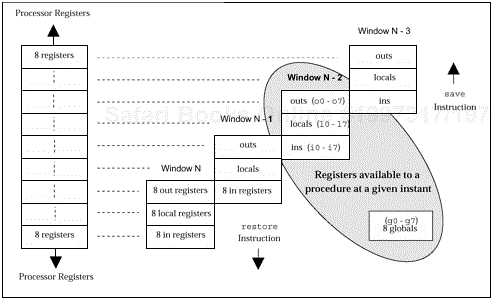
There are several ways to diagram the concept of windowing. As we discuss the save, call, and restore instructions, the method used below will help you visualize how the instructions affect the window view.
On SPARC systems, when a routine calls another routine, usually the first instruction of the new routine will be a save instruction. The saveinstruction actually does a lot of work, but we have no fears about it not completing its tasks. The only trap that can occur during a save is a window overflow.
The save instruction is the only instruction that decrements the window pointer, thus preserving the current window. In other words, according to the previous figure, our window view would shift from Window N-2 to Window N-3. As you can see, this would mean that the old output registers, %o0–%o7, would be the new input registers, %i0–%i7. The old local registers, %l0–%l7, would be outside of our new window view; however, we would have access to a new set of eight local registers with which to work.
The second thing the save instruction does for us is to push a new, empty frame onto the stack. Using the caller’s stack pointer for reference that is in the caller’s register %o6, (yes, which will become the callee’s %i6), the stack is grown downward by a certain amount and the new stack pointer is saved in the callee’s own %o6 register. Here is an example of a save instruction you might see. Note that %spis simply another name for %o6.
save %sp, -0x78, %sp
The first %sp refers to the caller’s stack pointer stored in the caller’s %o6register. The second reference to %sp refers to the callee’s stack pointer, which is stored in his own %o6. This may be easier to understand if you imagine that the window shift takes place between the time the CPU deals with the first and second %sp of the save instruction.
Were you surprised to learn that it is the responsibility of the callee and not the caller to shift the windows and adjust the stack via the save instruction? Let’s look at how the calling routine affects the callee’s registers.
The caller may invoke subroutines via either a call instruction or a jmpl instruction. The call instruction actually has the address embedded in the instruction itself as a 30-bit displacement from the current PC value. This signed offset allows the callinstruction to reach any location in memory. The address of the callinstruction itself is saved in register %o7.
call disp30 A long jump (jmpl) instruction can be used to call a function if the address is contained in a register. In this case, the address of the jmplis saved in whatever register is specified in the instruction, although this is normally %o7. A jmpllooks like the following, where address is the location of the routine we wish to jump to.
jmpl address, %o7 This instruction says to jump to address, saving the current PC in register %o7. You know what we plan to do with that saved PC value, right? It’s going to become the %i7value after the save instruction is completed and will be put into the callee’s frame at fr_savpc.
Note that the return address is not actually the place we wish to return to, but rather the place we came from.
Maybe you’ve already guessed it! restoreis the instruction that shifts the current window view back to the caller’s window. The restoreinstruction basically pops the callee’s frame off the stack, bringing us back to the previous window and the previous %sp or %o6. The contents of memory don’t actually change.
The restore instruction does not return us to the calling routine. For that, we must perform a jump-and-link or jmpl instruction. It is during this jump instruction that we use the saved PC value in %i7. Again, this is the value we will see in the callee’s stack frame at fr_savpc.
The synthetic SPARC assembly instruction, ret, does the jump for us and really is just the instruction shown below. This instruction says to jump to the location referenced in %i7 plus 8 bytes or 2 full words and save our current PC in %g0.
jmpl %i7+8, %g0
Think of %g0 as the /dev/null of registers. Reading and writing to %g0always results in a zero. So, even though we say to store the PC in %g0, nothing actually happens. All we are doing is jumping back into the calling routine.
The man in the back wants to know why are we jumping to the saved PC+8 instead of PC+4. A good question!
The architecture of SPARC processors includes a pipeline. This pipeline overlaps execution of instructions, so that while the call that got us here was being processed, the next instruction was being fetched and started. Therefore, while we are doing the jump to the new routine, we are actually also executing the instruction at PC + 4. When we return to the calling routine, we are returning to the next instruction that we have not yet executed, which is at PC+8.
Note
For conditional branch instructions, there is a way of saying “Please don’t execute the delay instruction, just do the branch”; however, no such feature exists for jmpl.
Okay, now it’s time for us to return to our calling routine. This is done with two instructions. The first is the jump instruction. The second command shifts the window. Remember, even though we have jumped, the restore instruction gets executed by virtue of the SPARC pipeline architecture — it’s in the delay slot. So, finally, here is what you can expect to see at the end of a routine.
ret
restore
Hopefully, you’ve a funny feeling that there’s still a piece missing, because there is. We’ve talked about how the SPARC registers are used and how our windowed view of them changes when the save and restore instructions are executed. But who actually writes the register values into the stack frame in memory?
The short answer is: the operating system.
There is a WIM (Window Invalid Mask) register that keeps track of which windows are in use. There’s also a CWP(Current Window Pointer) field in the PSR(Processor Status Register) that keeps track of which window is currently in view. These are discussed in more detail in Appendix A.
Whether you have 40 registers available or 4000, there are a limited number of windows on any system. At some point in time, when we try to execute a save,we will run out of windows and have to start recycling those we’ve already used. This condition is recognized by the hardware, through use of the WIM and the CWP, and triggers a window overflow trap.
The window overflow trap must be processed by the operating system. When the operating system is UNIX, the kernel moves the window registers onto the stack in memory for safekeeping. It also handles the restoration of window registers via the window underflow trap, which occurs when you have restored so often you need to retrieve old information from the stack.
Window overflows and underflows start occurring early on in the execution of the UNIX operating system. It is only down in the lowest levels of the kernel that we would ever see instances where window overflows and underflows do not occur.
While technically incorrect, it is probably safe for UNIX users on SPARC processors to think of the save instruction as being the one that puts the values of the new input registers into the callee’s stack frame. However, it is important to remember that for each different hardware architecture that you encounter, you will invariably find differences at this low level, both in the hardware involved and in the UNIX kernel for that hardware.
We’ve talked about the stack in rather generic terms and how it grows. We’ve taken a look at a specific hardware architecture’s stack frame structure. We’ve gotten down into the intricacies of the SPARC processor, talking about registers and windows. We’ve explained the magic behind the SPARC assembly instructions used when moving from routine to routine. And we’ve talked about how the UNIX kernel supports the SPARC windowing concept and helps maintain the stack.
By now, you should be itching to see all of this work for you on your own system! In the next chapter, we will compile our simple little program and, executing it under the control of adb, we’ll step through it, watching the registers change and our stack grow.


