Chapter 6. Implementation Model
• Summary
The implementation model represents the physical composition of the implementation in terms of Implementation subsystems and implementation elements (directories and files, including source code, data, and executable files). The implementation subsystem is a way to reduce complexity in an implementation model containing hundreds of elements. A good way to think of the implementation subsystem is as the implementation model version of the design package. Like all the model-to-model mappings, the implementation model can be mapped very closely or very loosely to the design model. However you decide, it is best to keep the mapping one to one; that is, one design package should be mapped to one implementation subsystem. This allows for easy and seamless traceability from design to code.
The Rational Software Architect theory of operation is to use platform-neutral models through design and then have Rational Software Architect transform these designs, through model-to-code transformations, into code or implementation levels. As needed, the design can be updated and the changes transformed again into code. Then, at the code level, Rational Software Architect allows you to simply visualize the code in a UML format.
Persistence Choices
Implementation is where the choices for persistence are realized. This is not to say that these decisions were not made earlier, but from a modeling point of view the design model should be persistence agnostic as much as possible in order to keep your options open. However, during implementation, persistence is no longer conceptual and must be realized through a variety of means. For many applications, persistence is achieved through storing information in a relational database. However, many times persistence of information is accomplished through the use of enterprise information systems such as CICS or IMS. The number of choices for persistence, and therefore the number of application programming interfaces (APIs), keeps growing.
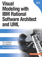
For the ESU Course Registration System, the information is stored in a relational database. During development we will use IBM DB2 Universal Database (a copy for development purposes is supplied with Rational Software Architect), although since the database is relatively simple, almost any database would work.
![]()
A.6.1
Figure 6-1 shows the database layout for a portion of the ESU Course Registration System. Note that Rational Software Architect also includes some data modeling capabilities and those were used to create this diagram. The Data Definition Language (DDL) statements to both create and populate the database are available from the book's Web page (http://www.ibmpressbooks.com/title/0321238087).
Once the persistence choice is made, another decision is how to access that persistence from the application. There is no shortage of options and frameworks, ranging from simple so-called data beans that encapsulate the Java Database Connectivity (JDBC) connections and calls to more sophisicated frameworks such as the J2EE standard Enterprise Java Bean (EJB) Entity Beans. Each has pluses and minuses, and the developer should weigh this decision carefully, taking into account the needs of the application, any enterprise standards, how long the application is expected to “live,” the skill and experience of the development team, and so on. A good overview of object/relational persistence is provided in Patterns of Enterprise Application Architecture, by Martin Fowler (Boston: Addison-Wesley, 2003).
We will be examing the implementation for the Browse Course Catalog use case. As you may recall from the interface diagram in the design model, there are two pages: browsecataloghome and courseofferings. The main implementation details we will be concerned with are how to surface the database information onto the Web pages. We would prefer to shield the Web page developer from the details of how the data is retrieved.
Service Data Objects
Service data objects (SDO) is an open standard specification for a programming model that not only provides uniformity among data sources, but also does the following:
• Provides robust support for common application patterns
• Enables applications, tools, and frameworks to more readily query, bind, view, update, and introspect data
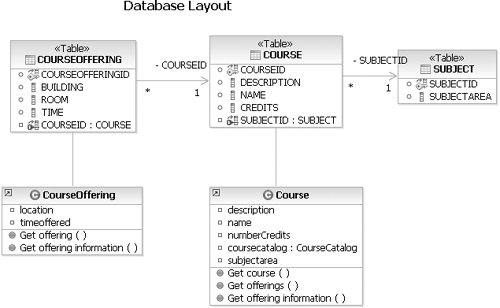
The goal is to simplify access to various data types and expose a common API to developers and tools. There are three main components involved:
• The data source
• The SDO datagraph
• The data source mediator
The data source is the place where data is stored. It can be just about anything—relational databases accessed through JDBC, EJBs, enterprise information systems such as CICS or IMS, or XML documents.
The SDO datagraph is a disconnected, source-independent, and structured result set. The datagraph is independent of connections to the originating data store. The datagraph also can identify and remember changes made from its original state. This capability allows the mediator to easily extract changes and move them to a data source. The datagraph structure is independent of data sources. In fact, different data source types can produce identical datagraphs. This feature unifies the client-programming model and allows for the creation of GUI tools that can work identically across different data source types.
The data source mediators are components that provide access to a specific data source type. They create SDO datagraphs by reading data from the data source, then propagating updates to the datagraphs back to the data source. Clients of the SDO runtime use a mediator specific to the data source type to retrieve a datagraph. Clients can then work with the data contained in the graph and make changes.
Mediators need to be configured to provide the desired functionality. This configuration information is referred to as the mediator’s metadata. The metadata contains a variety of information, such as:
• The source-specific data artifacts being accessed
• A selection of fields that the applications will typically use
• The filters that apply selection criteria on retrievable data
• The actions to perform on the data source
Sometimes a picture is worth a thousand words. See Figure 6-2 for a high-level diagram of Service Data Objects.
Figure 6-2. Service Data Object Diagram
In short, SDO simplifies development, providing one unique API to access heterogeneous data sources. From a development point of view, this means we only have to learn one API to access these disparate data sources. This is also good from a tool point of view because a development tool only has to work with one API to access these data sources.
User Interface Choices
A.6.2
There are many choices when it comes to the user interface. Two that come to mind immediately are a self-contained rich client user interface and a Web-based user interface. The rich client user interface typically offers a richer, more powerful set of controls with a large amount of local processing on the user’s computer. The Web-based user interface typically provides very simple controls, such as text boxes, drop-down boxes, and buttons, with the bulk of the processing occurring on the server.
Each has pluses and minuses. A rich client user interface will usually offer more functionality and can take better advantage of the native capabilities of the platform. However, a rich client implies the installation and maintenance of that program on the client device as well as different versions of the program for different devices, and this is not always desired or practical. A Web-based user interface will typically offer less functionality and tends to be less sophisticated. Note that more recent programming models have started to change this so Web-based user interfaces are becoming more capable. Also, Web browsers are fairly universal, and installation and maintenance is required only at the server versus for each client. A well-layered system will separate the user interface from the rest of the system so that the choice of the user interface layer has no impact on the rest of the system, and thus the user interface can evolve as required. In fact, a properly layered system can support multiple user interface choices with minimal impact on the other layers.
![]()
A.6.3
For the ESU Course Registration System, we want users to be able to access the system from any system at any time, requiring only a connection to the Internet. This means a Web-based user interface. The next decision we need to make is which Web application framework to use. There are a number of popular ones, including Java Web frameworks such as Apache Struts and JavaServer Faces, .NET’s ASP.NET, and Ruby on Rails. A Web application framework is a set of tools that make it easier to develop Web applications. The application is easier to debug, easier to extend, and easier to understand.
Struts is a popular framework from the Apache Software Foundation. The centerpiece of Struts is its model-view-controller (MVC)-style controller, which integrates with other technologies that provide the model and the view.1 For the model, Struts can interact with standard data access technologies such as JDBC and EJB. For the view, Struts works well with JSP, including the JSP Standard Tag Library (JSTL) and JavaServer Faces (JSF) and other presentation systems.
![]()
A.6.4
Rational Software Architect has good support for building Struts-based Web applications. However, Struts is slowly falling out of favor for new applications, a victim of its own success. It became so popular that its shortcomings were magnified. For example, Struts does not come with a very rich set of user interface components. One of the strengths of Struts is its sophisticated page flow framework. The ESU Course Registration System will not be very complex, so we really don’t need this level of sophistication. Finally, looking to the future, we might want the flexibility to render something besides standard HTML if we want to support other devices or markup languages, and Struts does not make provisions for that.
Obviously, the current and future needs of the application or enterprise will dictate what framework is used. Some enterprises even customize one of the frameworks for their own use with unique taglibs and components. The gains in productivity for doing this must be weighed against the cost of developing and maintaining these customizations.
JavaServer Faces
Javaserver faces (JSF) is an open standard technology that helps you build user interfaces for dynamic Web applications that run on the server. The JSF framework manages user interface states across server requests and offers a simple model for the development of server-side events that are activated by the client. JSF is consistent.
The main components of JSF technology include:
• An extensive set of reusable user interface components
• A set of APIs for representing and managing user interface components, for handling events and input validation, and for defining page navigation
• A JavaServer Pages (JSP) custom tag library for expressing a JSF interface within a page
JSF is used to build Web applications. JavaServer Faces is also based on an MVC framework. For JSF, this means that the controller is a servlet, the model is represented by simple JavaBeans, and the view comprises JSF components with little or no application code. The goal of this model is to separate content from presentation.
Like many frameworks, the devil is in the details. You can certainly develop JSF-based applications “by hand,” that is, hand coding all the files including the configuration files. However, many people will find that using a tool such as Rational Software Architect for JSF development is faster, quicker, and less error prone. Rational Software Architect supports dragging and dropping a set of standard JSF widgets that make building JSF-based pages easy.
The standard JSF renderer is for HTML. That is, there is a JSF life cycle that controls the processing of JSF requests. The last phase is to render the response into a form that can be used by the requesting client, and the standard renderer transforms the response into HTML. However, JSF is flexible enough so that other renderers could be written for other non-HTML clients as needed.
As with any technology, a best practice is to begin JSF development by hand and then move to using the tools once the programming model is understood. If you do not learn the programming model at the beginning, you will eventually hit situations where that knowledge is needed. It’s a case of pay now or pay later. For this book, we will just use the tools and not cover the details. For readers interested in more detail on JSF, a great reference is chapter 18, “Using JavaServer Faces Technology in JSP Pages,” from The J2EE™ Tutorial, Second Edition, by Stephanie Bodoff et al. (Boston: Addison-Wesley, 2004) or Core JavaServer Faces, by Geary and Horstmann (Sun Microsystems Press Java Series, 2004).
![]()
A.6.5
Given the nature of the ESU Course Registration System, JSF is an appropriate choice. We want to maintain flexibility for future device types, we want to take advantage of some of the rich user interface components of JSF, our Web page navigation will not be complex, and we want a simple development experience.
Tying It Together
Now that we have covered the concepts, let’s get to work. As noted, we have decided to use JSF and Service Data Objects. For the Browse Course Catalog use case, we also know we will need to create two pages (browsecataloghome and courseofferings). These pages need to exist inside a dynamic Web project, and, of course, a dynamic Web project will need to be part of a J2EE Enterprise project. Working on dynamic Web pages means we will have to enable the Web development capabilities of Rational Software Architect.
![]()
- Click File > New > Other, and select Dynamic Web Project. Click the Next button. When asked, confirm the enablement of Web development capabilities.
- Give the Web project a meaningful name, such as ESUCourseRegistration. Using blanks, spaces, or special characters is not recommended.
- Click the Finish button.
- When asked, switch to the Web perspective.
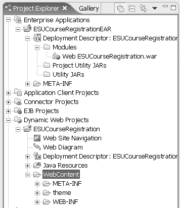
By expanding Enterprise Application and Dynamic Web Projects in the Project Explorer in the Web perspective as shown in Figure 6-3, we can see what was created. There is the enterprise application ESUCourseRegistrationEAR containing the dynamic Web project ESUCourseRegistration, and of course, the dynamic Web project itself.
Figure 6-3. Initial Dynamic Web Project
Now that we have the basic structure, it’s time to fill it out. There are a number of ways to do this within Rational Software Architect. One way that allows you to see the relationship of JSF pages to one another is the Web diagram. A Web application diagram, or Web diagram, is a file that helps you visualize and change the flow of a Web application such as a JSF or Struts-based application. The Web diagram editor is a visual editor for editing Web diagrams. Many frameworks rely on XML configuration files that are perfectly fine for computers to read but which are hard for people to read and edit. The Web diagram editor updates the XML configuration files, allowing you to work at a higher level of abstraction.
To open the Web diagram editor, in the Project Explorer, double-click on Dynamic Web Projects > ESUCourseRegistration > Web Diagram. This displays an “empty” Web diagram that displays some initial help, as shown in Figure 6-4.
Figure 6-4. “Empty” Web Diagram
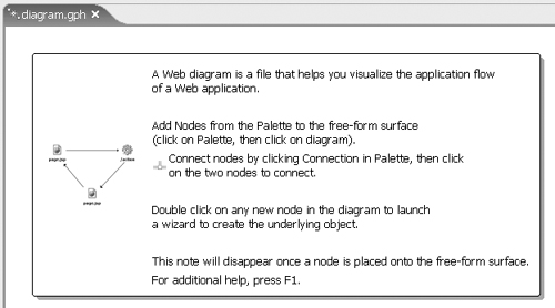
A Web diagram consists of nodes and connections between nodes. A node is an icon that represents a resource such as a Web page, Java bean, or Web application.
If the resource exists, the node is called realized. If the resource does not exist, the node is called unrealized. That is, if the Web page is not yet created, it is unrealized. Realized nodes are shown in color with their names in boldface. Unrealized nodes are shown as gray icons.
Remembering our design, we need to add two Web pages (two nodes) to the diagram.
![]()
- From the palette area to the right of the Web diagram, right-click Web Page (in the Web Parts) folder.
- Position the mouse pointer over the Web diagram (as shown in Figure 6-5).
Figure 6-5. Dropping a Web Page
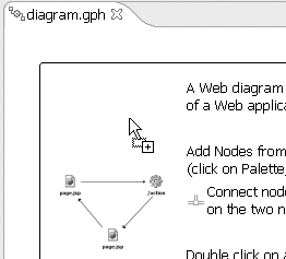
- Right-click to drop the new Web page onto the Web diagram.
- Enter a file name such as browsecataloghome (note that you don’t have to type .jsp; that is entered for you).
- Repeat these steps for a second Web page called courseofferings so the Web diagram looks like Figure 6-6.
Figure 6-6. Web Diagram with Pages
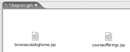
Remember that nothing has been created because all the resources are unrealized and thus are displayed as gray icons or dotted lines. Let’s create the Web pages.
![]()
- In the Web diagram, double-click on browsecataloghome.jsp.
- Click on Finish.2
- Delete the text “Place content here.”
- Return to the Web diagram and repeat these steps for courseofferings.jsp to create it.
If you look at the Web diagram, both browsecataloghome.jsp and courseofferings.jsp are shown with color and boldfaced names, because they now exist.
Now, as you may recall from the design model Interface Diagram, users enter their search criteria on the browsecatalog screen, and the search criteria are by subject. We could have users type in a subject area and do a text search, but that would mean either the users would have to know the subject areas in advance and type them in correctly or our application would have to do some complicated text-matching algorithm. Neither is appealing for this application. It would be better if we presented users with a list of subjects and let them select the subject from the list. We could create the list from the subjects we know about today, but this would mean that when a new subject was added, we would have to change the list. This makes our application less flexible and more brittle. Instead, it would be nice if we could create a list of subjects on the fly as the application is running. From a database implementation point of view, this means we should have a table of subject areas and a relationship between the course table and the subject areas table. This has been done for the ESU database system.
The ideal implementation would hide these details from the Web page so the Web page would not have to change regardless of how the database tables are structured. As discussed earlier, Service Data Objects can abstract out the details of the persistance model, so we will use Service Data Objects for interacting with the database. Advanced JSF developers could create custom JSF components that would allow page designers to drop in custom controls and further customize the controls via XML attributes (as opposed to having to write lots of generic tags or complex logic in JSP pages).
Note that the steps in this next exercise assume IBM DB2 Universal Database as the database and would need to be modified slightly depending on the database you use. It also assumes the database has been created and matches Figure 6-1. Finally, these steps keep the default names when provided, although realistically you would use more meaningful names.
Make sure you are back in the Web perspective before you start.
Creating a Data Connection and a Data Object
![]()
- Select browsecataloghome.jsp for editing.
- Left-click in the Page Data area to the bottom left of the Web page editor and select New > Relational Record List. This will start the Relational Record List wizard.
- On the Relational Record List page of the Add Relational Record List wizard, enter “subjectlist” as the name of the record list and click Next.
- On the Record List Properties page of the Add Relational Record List wizard, click the New button to create a new connection to the database.
- On the Select a Database page of the New Connection wizard, click Create New DB Connection.
- On the Establish a Connection to a Database page of the New Database Connection wizard, click Next.
- On the Specify Connection Parameters page of the New Database Connection wizard, select the appropriate Alias name, such as COURSECAT, and enter the appropriate security information, such as userid and password.
- Click Test Connection and validate you can connect to the database. If not, correct any errors until you can connect.
- Click Finish.
- Back on the Select a Database page of the New Connection wizard, click Finish to finish creating the connection.
- On the Record List Properties page of the Add Relational Record List wizard, select the table we want to connect to, in this case, the SUBJECT table, and click Next.
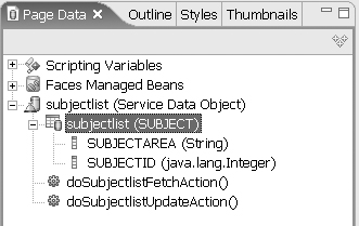
- Note that you can select which columns from the database will be part of the data object. We will keep them all, so click Finish.
The service data object is created, as shown in Figure 6-7.
Figure 6-7. Service data object
Now we need to display the information from the service data object on the page. We will create a data table and bind the service data object fields to the data table fields. A data table is a JSF component used to display application data. It consists of one or more columns, each with a header area and a data area, the data area repeating for each record. We could add a data table and then bind the columns to the service data object manually, but we will instead drag and drop the service data object to the page and let Rational Software Architect do this for us.
Creating a Data Table from a Service Data Object
![]()
- Click and hold the subjectlist table in the subjectlist service data object (not the service data object itself).
- Position the mouse pointer over browsecataloghome.jsp and release the mouse button.3 This starts the Insert Record List wizard.
- On the Configure Data Controls page of the Insert Record List wizard, deselect SUBJECTID. SUBJECTID is only used internally and does not have to be displayed to the user.
- Change the label from Subjectarea to Subject Area and click Finish.
The data table is created and linked to the service data object, as shown in Figure 6-8.
Figure 6-8. Data Table Bound to Service Data Object
Remembering the design, once a user selects a subject area, a page should be displayed with all the courses for that subject area, and once a user selects a course, that page should be refreshed with the course offerings for that course. While this can be done with JSF, we decide to make the interface a little less complicated for the first version in order to speed up development. Creating pages that refresh with an updated user interface takes more time to develop and test. These types of pragmatic decisions are made all the time, weighing various trade-offs. Each enterprise should have a process in place to govern whether or not these implementation decisions get back into the design.
Getting back to the actual implementation, we will first add a column to the data table and then add something called a command hyperlink to pass a parameter to the courseofferings.jsp page.
Adding a Column to a Data Table
![]()
- In browsecataloghome.jsp, select the data table. This can be a little tricky, but try selecting anywhere in the data table and looking at the Properties view down at the bottom. If h:dataTable is not selected, select it in the Properties view (see Figure 6-9).
Figure 6-9. Selecting a Data Table
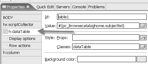
- In the Columns area of the dataTable properties, click the Add button to add a new column.
- Change the label for the column to Course Offerings (see Figure 6-10).
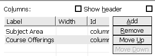
The data table has a new column.
Adding a Command Hyperlink and Parameter
![]()
- In the Palette area of the page editor, click the Command – Hyperlink component in the Faces Components folder.
- Position the mouse pointer in the column that was just added to the data table and click again.
- Select the Command Link icon in the data table.
- In the Properties view, under h:commandLink, click on Parameter and then click Add Parameter.
- Change the name of the parameter from Name0 to ID.
- Change the value of the parameter from Value0 by clicking Value0 and then clicking the Select Page Data Object icon that appears to the right of Value0.
- On the Select Page Data Object page, expand subjectlist > subjectlist and select SUBJECTID (see Figure 6-11) and click OK.
Figure 6-11. Selecting a Parameter Variable
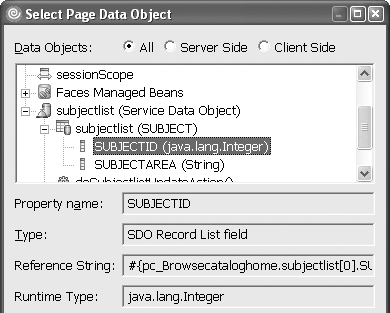
This should result in the parameter being set as shown in Figure 6-12.
Figure 6-12. Parameter Setting

These steps created a clickable link for the data table and also specified a parameter to pass with the link, the parameter being the SUBJECTID of the subject the user clicks on.
The last thing we need to do for this page is to specify which page to display when the link is clicked.
![]()
- In the Properties view, click on h:commandLink.
- In the Rules area of the Properties, click on Add Rule. . . .
- On the Add Navigation Rule page, use the drop-down arrow next to the Page input field to select courseofferings.jsp and click OK. Note that more complex rule conditions can be added.
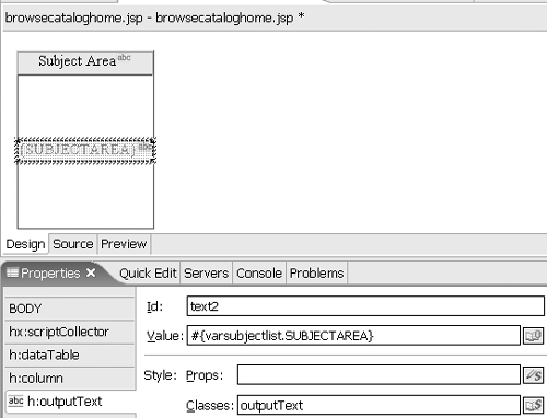
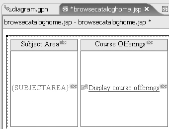
- In the Data Table, click “link label.”
- In the Properties view, change the Value from “link label” to “Display course offerings.”
This should result in a browsecataloghome.jsp something like Figure 6-13.
Figure 6-13. Completed browsecataloghome.jsp
Browsecataloghome.jsp is now complete, so we will turn our attention to courseofferings.jsp. The design tells us we should display all the course offerings for the selected subject area. We just added subject area ID as a parameter (called ID) to the command link for courseofferings.jsp, so we need to filter or limit the courses it displays to just those that have the same subject area ID.
![]()
- Select courseofferings.jsp for editing.
- Left-click in the Page Data area to the bottom left of the Web page editor and select New > Relational Record List. This will start the Relational Record List wizard.
- On the Relational Record List page of the Add Relational Record List wizard, enter courselist as the name of the record list and click Next.
- On the Record List Properties page of the Add Relational Record List wizard, ensure that the connection that was created for the earlier service data object is selected (the name should be something like ESUCourseRegistration_Con1) and select the table we want to connect to (in this case, the COURSE table), and click Next.
- On the Column Selection and Other Tasks page of the Add Relational Record List wizard, click the Filter Results link.
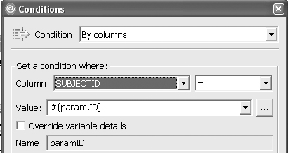
- On the Filters page, click the big + symbol to add a new filter.
- On the Conditions page, use the drop-down arrow to select the SUBJECTID column and enter #{param.ID} as the value (see Figure 6-14) and click OK.
Figure 6-14. Entering a Filter
- Back on the Filters page, click Close.
- Back on the Column Selection and Other Tasks page of the Add Relational Record List wizard, click Finish.
This creates a new service data object called courselist.
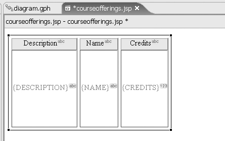
Drag and drop the new service data object onto courseofferings.jsp to create a new data table, displaying the columns as shown in Figure 6-15.
Figure 6-15. Courseofferings.jsp Data Table
Now is where we start deviating slightly from the design. When the user selects a course offering, we want to display a new page with the course offering details. Go back to editing the Web diagram (the file called diagram.gph). Add a new page called courseofferingsdetail.jsp and create it by double-clicking on it, again removing the default “place content here” text from the page.
We have to have some way to pass the course ID from courseofferings.jsp to courseofferingsdetail.jsp. Recall that we used automatic parameter passing between browsecataloghome.jsp and courseofferings.jsp. This is only supported for the commandLink component, and we will be using a different component this time. One popular way to pass parameters is through the use of scripting variables. We will create a new scripting variable to pass the course ID from one page to the next.
![]()
- Select courseofferingsdetail.jsp for editing.
- Left-click in the Page Data area to the bottom left of the Web page editor and select New > Scripting Variable > Session Scope Variable.
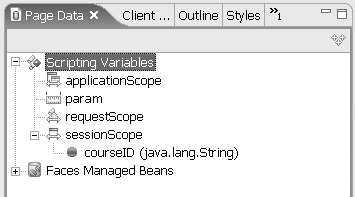
- On the Add Session Scope Variable page, enter courseID for the variable name and java.lang.String for the variable type and click OK.
This will result in a new request scope variable, as shown in Figure 6-16.
Figure 6-16. New Session Scope Variable
Next we will create a new service data object that will filter course offering details to just those courses.
![]()
- Select courseofferingsdetail.jsp for editing.
- Left-click in the Page Data area to the bottom left of the Web page editor and select New > Relational Record List. This will start the Relational Record List wizard.
- On the Relational Record List page of the Add Relational Record List wizard, enter courseoffering as the name of the record list and click Next.
- On the Record List Properties page of the Add Relational Record List wizard, ensure that the connection that was created for the earlier service data object is selected (the name should be something like ESUCourseRegistration_Con1) and select the table we want to connect to (in this case, the COURSEOFFERING), table and click Next.
- On the Column Selection and Other Tasks page of the Add Relational Record List wizard, click the Filter Results link.
- On the Filters page, click the big + symbol to add a new filter.
- On the Conditions page, use the drop-down arrow to select the COURSEID column and click the box with the three periods next to Value.
- On the Select Page Data Object page, expand sessionScope and select courseID (see Figure 6-17) and click OK.
Figure 6-17. Selecting a Data Object
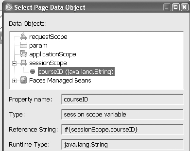
- Back on the Conditions page, click OK.
- Back on the Filters page, click Close.
- Back on the Column Selection and Other Tasks page of the Add Relational Record List wizard, click Finish.
This creates a new service data object called courseoffering.
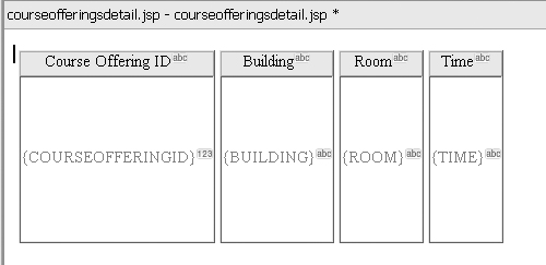
Drag and drop the new service data object onto courseofferingsdetail.jsp to create a new data table, displaying the columns as shown in Figure 6-18.
Figure 6-18. Courseofferingsdetail.jsp Data Table
Save your work by pressing the Crtl, Shift, and S keys all at once. This saves all the changes on all files.
All that is left to do is to pass the parameter from courseofferings.jsp into the scripting variable. For this we will add a row action to the data table. This will allow the user to click anywhere on that row to perform an action—in this case, setting the scripting variable and displaying a new page with the course offering details on it.
First we will add a row action.
![]()
- Select courseofferings.jsp for editing.
- Select the data table. This can be a little tricky, but try selecting anywhere in the data table and looking at the Properties view down at the bottom. If h:dataTable is not selected, select it in the Properties view.
- Under h:dataTable in the Properties view, click Row actions.
- Click the Add button for “Add an action that’s performed when a row is clicked.”
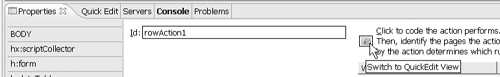
This creates a row action as shown in Figure 6-19. Press Ctrl+S to save this file.

Now, click on the QuickEdit button to switch to the QuickEdit view (see Figure 6-20).
Figure 6-20. Switching to QuickEdit
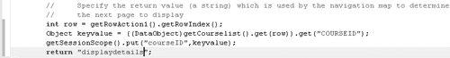
You will see a number of commented lines of Java code. These lines guide you through the process of adding the appropriate lines of Java code to pass parameters. We will add three lines of Java code to the bottom, just before the return instruction. Scroll to the bottom of the QuickEdit code and just before the return ""; line, add these three lines:
int row = getRowAction1().getRowIndex();
Object keyvalue =
((DataObject)getCourselist().get(row)).get("COURSEID");
getSessionScope().put("courseID",keyvalue);
The first line sets the variable row to the row number the user clicked on. The second line sets keyvalue to the COURSEID from that row (even though COURSEID is not displayed, it is present in the service data object). The third line puts that course ID into the script variable.
Finally, we will return a value for the JSF navigation map. Change the return "" ; line to return "displaydetails";.
The completed code should match Figure 6-21.
We need to add a navigation rule for this page. Now, click on the Properties tab to move from the QuickEdit view to the Properties view. If commandExRowAction is not selected, select it.
![]()
- Click on the Add Rule button to add a navigation rule.
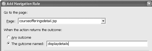
- On the Add Navigation Rule page, use the drop-down arrow to select courseofferingsdetail.jsp as the page.
- Select the radio button next to “The outcome named” and enter displaydetails (see Figure 6-22) and click OK.
Figure 6-22. Adding a Navigation Rule
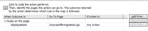
This creates a navigation rule, as shown in Figure 6-23.
Figure 6-23. A Navigation Rule
Save your work by pressing the Ctrl, Shift, and S keys together.
Now to test our work. The following steps assume that the default WebSphere Application Server V6 was installed with Rational Software Architect.
![]()
- Go back to the Web diagram (diagram.gph).
- Right-click on browsecataloghome.jsp and select Run on Server....
- On the Define a New Server page, click Finish.
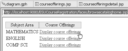
- Once the server starts and browsecataloghome.jsp is displayed in the built-in browser, click on one of the “Display course offerings” links (see Figure 6-24).
Figure 6-24. Running browsecataloghome
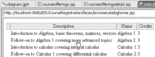
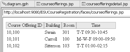
- This will display the courseofferings.jsp page in the built-in browser. Click on one of the rows (see Figure 6-25).
Figure 6-25. Running courseofferings.jsp
- This will display the courseofferingsdetails.jsp page in the built-in browser (see Figure 6-26).
Figure 6-26. Running courseofferingsdetails.jsp
Well, the formatting of the Course Offering ID could be better, but that can be corrected by modifying the properties of the field.
We could easily imagine using another row action or command link for the actual course registration.
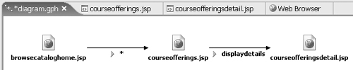
Finally, let’s go back to the Web diagram. Right-click on browsecataloghome.jsp and select Draw > Draw All. This will show the various actions and links we added so the flow of the pages is better understood, as shown in Figure 6-27.
Figure 6-27. Updated Web Diagram
This completes this part of the implementation. This should be tested with potential end users to see if it meets their needs.
Summary
The implementation model represents the physical composition of the implementation in terms of implementation subsystems and implementation elements
The choice of persistence is an important decision that will most likely be influenced by existing standards, but the implementation should be layered in such as way that the persistence choice can be changed as needed. Service Data Objects is one such way.
There are a number of popular Web application frameworks with which you can build a Web application, including Struts and JavaServer Faces.
Rational Software Architect includes a number of capabilities that make creating data-centric Web applications fairly fast.
developerWorks Links
A.6.1 DB2 Universal Database support and trial software. developerWorks: http://www.ibm.com/developerworks/downloads/im/udb/index.html?S_TACT=105AGX28&S_CMP=DLMAIN
A.6.2 Service Data Object specification. developerWorks, November 2005: http://www.ibm.com/developerworks/webservices/library/specification/ws-sdo/
A.6.3 Berry, D. The user experience, Part 1. developerWorks, February 2005: http://www.ibm.com/developerworks/web/library/w-berry2.html
A.6.4 Davis, M. Struts, an open source MVC implementation. developerWorks, February 2001: http://www.ibm.com/developerworks/java/library/j-struts/
A.6.5 Hightower, R. JSF for nonbelievers (four-part series). developerWorks, starting February 2004: http://www.ibm.com/developerworks/java/library/j-jsf1/