
Cocoa’s Application Kit provides you with a wide array of ready-made user interface objects. However, most complex applications will require at least a few custom interface elements. In addition, many applications need to perform custom drawing in order to display data. This appendix explains the basics of Cocoa’s imaging model and shows you how to create custom graphics.
In order to use the drawing facilities of Cocoa to their maximum potential, it is important to learn about Quartz, the imaging model underlying all graphics in Mac OS X. Quartz is based on Adobe’s Portable Document Format (PDF), which is in turn based on the Adobe PostScript imaging model. A complete description of Quartz, PostScript, and PDF is beyond the scope of this appendix. Look to the many excellent third-party books that are available, such as the PostScript Language Reference from Adobe (known as the “Red Book”) and the PDF 1.3 specification (http://www.pdfzone.com/resources/pdfspec13.html).
The screen coordinate system is the basis for all other coordinate systems used for positioning, sizing, drawing, and event handling. You can think of the entire screen as occupying the upper-right quadrant of a two-dimensional coordinate grid as shown in Figure 1.1. The other three quadrants, which are invisible to users, take negative values along their x-axis, their y-axis, or both axes. The screen’s quadrant has its origin in the lower-left corner; the positive x-axis extends horizontally to the right and the positive y-axis extends vertically upward. A unit along either axis is expressed as a pixel.
Note that although Figure 1.1 represents the screen coordinate system using the example of a single display device, the screen coordinate system is really a logical rectangular area that is determined by the union of all screen rectangles of all physical framebuffers attached to the computer. The origin lies at the lower-left corner of that unioned rectangle.
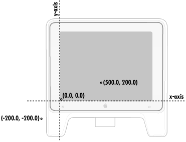
The screen coordinate system has just one function: to position windows on the screen. When your application creates a new window, it must specify the window’s initial size and location in screen coordinates.
The reference coordinate system for a window (Figure 1.2) is known as the base coordinate system. It differs from the screen coordinate system in only two ways:
It applies only to a particular window; each window has its own base coordinate system.
Its origin is at the lower-left corner of the window, rather than the lower-left corner of the screen. If the window moves, the origin and the entire coordinate system move with it.
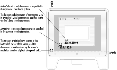
For drawing, each NSView (detailed in Chapter 8, and Section 1.3, later in this chapter) uses a coordinate system transformed from the base coordinate system or from the coordinate system of its superview. This coordinate system also has its origin point at the lower-left corner of the NSView, making it more convenient for drawing operations. NSView has several methods for converting between base and local coordinate systems. When you draw, coordinates are expressed in the application’s current coordinate system.
Before drawing into a particular NSView, focus has to be “locked” onto
that view (using NSView’s lockFocus method, which
you’ll learn more about later in this chapter). This causes NSView’s
coordinate system to become the current coordinate system; i.e., the
one to which all drawing commands apply.