
The Linux kernel supports many different network architectures (TCP/IP being just one of them), implements several alternative algorithms for scheduling the network packets, and includes programs that make it easy for system administrators to set up routers, gateways, firewalls, and even a simple World Wide Web server, directly at the kernel level.
The current code, inspired from the original Berkeley Unix implementation, is referred to as Net-4. As the name suggests, it is the fourth major version of Linux networking. Similar to VFS, the code uses objects to provide a common interface to the large number of available architectures. However, contrary to VFS, the networking code is organized into layers, each of which has a well-defined interface with the adjacent layers. Since data transmitted along the network is not reusable, there is no need to cache it. For the sake of efficiency, Linux avoids copying the data across layers; the original data is stored in a memory buffer, which is large enough to contain the control information requested by each layer.
Packing a detailed description of the Linux networking code in a single chapter of a book would be a truly impossible mission. In fact, nearly 20 percent of all kernel source code is devoted to networking. Therefore, we couldn’t even succeed, within the space constraints of a single chapter, in mentioning the names of all the features, components, and data structures of the Linux network subsystem.
Our objective is more limited. We concentrate on the well-known TCP/IP stack of protocols and consider only the data link layer, the network layer, and the transport layer. Furthermore, for the sake of simplicity, we focus our attention on the UDP protocol and attempt to give a succinct description of how the kernel succeeds in sending or receiving a single datagram. Finally, we assume that our computer is connected to a local area network by means of an Ethernet card.
The first section of the chapter covers the main data structures used by Linux networking, while the second one illustrates the system calls needed to send or receive a single datagram and describes sketchily the corresponding service routines. The last two sections describe how the kernel interacts with the network card to send or receive a packet.
We assume that you already have some background in network protocols, layers, and applications. There are many good books on these topics, some of which are listed in the Bibliography at the end of this book.
One final remark: writing programs for the network subsystem is quite a hard task. While you have to stick to the documented standards, following them is not enough because they do not specify the smallest, most cumbersome details of the protocols. Thus you have to take into account the implementations of the already existing network programs, even those in other operating systems (bugs included). And, of course, you must write fast and efficient programs; otherwise your server will not keep up with the highest network loads.
In this section, we shall give a general idea of how Linux implements the lower layers of networking.
A network architecture describe how a specific computer network is made. The architecture defines a set of layers , each of which should have a well-defined purpose; programs in each layer communicate by using a shared set of rules and conventions (a so-called protocol ).
Generally speaking, Linux supports a large number of different network architectures; some of them are listed in Table 18-1.
Table 18-1. Some network architectures supported by Linux
|
Name |
Network architecture and/or protocol family |
|---|---|
|
|
Appletalk |
|
|
Bluetooth |
|
|
Multiprotocol bridge |
|
|
DECnet |
|
|
IPS’s IPv4 protocol |
|
|
IPS’s IPv6 protocol |
|
|
Novell IPX |
|
|
Unix domain sockets (local communication) |
|
|
IPS’s IPv4/IPv6 protocol low-level access |
|
|
X25 |
IPS (Internet Protocol Suite) is the network architecture of Internet , the well-known internetwork that collects hundreds of thousands of local computer networks all around the world. Sometimes it is also called TCP/IP network architecture from the names of the two main protocols that it defines.
A network interface card (NIC) is a special kind of I/O device that does not have a corresponding device file. Essentially, a network card places outgoing data on a line going to remote computer systems and receives packets from those systems into kernel memory.
Starting with BSD, all Unix systems assign a different symbolic name
to each network card included in the computer; for instance, the
first Ethernet card gets the eth0 name. However,
the name does not correspond to any device file and has no
corresponding inode in the system directory tree.
Instead of using the filesystem, the system administrator has to set up a relationship between the device name and a network address. Therefore, as we shall see in the later section Section 18.2, BSD Unix introduced a new group of system calls, which has become the standard programming model for network devices.
Generally speaking, any operating system must define a common Application Programming Interface (API) between the User Mode program and the networking code. The Linux networking API is based on BSD sockets. They were introduced in Berkeley’s Unix 4.1cBSD and are available in almost all Unix-like operating systems, either natively or by means of a User Mode helper library.[117]
A socket is a communication endpoint — the terminal gate of a channel that links two processes. Data is pushed on a terminal gate, and after some delay, shows up at the other gate. The communicating processes may be on different computers; it’s up to the kernel’s networking code to forward the data between the two endpoints.
Linux implements BSD sockets as files that belong to the
sockfs special filesystem (see Section 12.3.1). More precisely, for every new BSD socket,
the kernel creates a new inode in the sockfs
special filesystem. The attributes of the BSD socket are stored in a
socket data structure, which is an object included
in the filesystem-specific u.socket_i field of the
sockfs’s inode.
The most important fields of the BSD socket object are:
-
inode Points to the sockfs’s inode object
-
file Points to the file object of the sockfs’s file
-
state Stores the connection status of the socket:
SS_FREE(not allocated),SS_UNCONNECTED(not yet connected),SS_CONNECTING(in process of connecting),SS_CONNECTED(connected),SS_DISCONNECTING(in process of disconnecting).-
ops Points to a
proto_opsdata structure, which stores the methods of thesocketobject; they are listed in Table 18-2. Most of the methods refer to system calls that operate on sockets. Each network architecture implements the methods by means of its own functions; hence, the same system call acts differently according to the networking architecture to which the target socket belongs.
Table 18-2. The methods of the BSD socket object
|
Method |
Description |
|---|---|
|
|
Close the socket |
|
|
Assign a local address (a name) |
|
|
Either establish a connection (TCP) or assign a remote address (UDP) |
|
|
Create a pair of sockets for two-way data flow |
|
|
Wait for connection requests |
|
|
Return the local address |
|
|
Implement |
|
|
Initialize the socket to accept connection requests |
|
|
Close a half or both halves of a full-duplex connection |
|
|
Set the value of the socket flags |
|
|
Get the value of the socket flags |
|
|
Send a packet on the socket |
|
|
Receive a packet from the socket |
|
|
File memory-mapping (not used by network sockets) |
|
|
Copy data directly from/to a file ( |
-
sk Points to the low-level
struct socksocket descriptor (see the next section).
INET sockets
are data structures of type
struct
sock. Any BSD socket
that belongs to the IPS network architecture stores the address of an
INET socket in the sk field of the
socket object.
INET sockets are required because the socket
objects (describing BSD sockets) include only fields that are
meaningful to all network architectures. However, the kernel must
also keep track of several other bits of information for any socket
of every specific network architecture. For instance, in each INET
socket, the kernel records the local and remote IP addresses, the
local and remote port numbers, the relative transport protocol, the
queue of packets that were received from the socket, the queue of
packets waiting to be sent to the socket, and several tables of
methods that handle the packets traveling on the socket. These
attributes are stored, together with many others, in the INET socket.
The INET socket object also defines some methods specific to the type
of transport protocol adopted (TCP or UDP). The methods are stored in
a data structure of type proto and are listed in
Table 18-3.
Table 18-3. The methods of the INET socket object
|
Method |
Description |
|---|---|
|
|
Close the socket |
|
|
Either establish a connection (TCP) or assign a remote address (UDP) |
|
|
Relinquish an established connection |
|
|
Wait for connection request |
|
|
Implement |
|
|
INET socket object constructor |
|
|
INET socket object destructor |
|
|
Close a half or both halves of a full-duplex connection |
|
|
Set the value of the socket flags |
|
|
Get the value of the socket flags |
|
|
Send a packet on the socket |
|
|
Receive a packet from the socket |
|
|
Assign a local address (a name) |
|
|
Callback function invoked when receiving a packet |
|
|
Add the INET socket to the per-protocol hash table |
|
|
Remove the INET socket from the per-protocol hash table |
|
|
Assign a port number to the INET socket |
As you may notice, many methods replicate the methods of the BSD socket object (Table 18-2). Actually, a BSD socket method usually invokes the corresponding INET socket method, if it is defined.
The sock object includes no less than 80 fields;
many of them are pointers to other objects, tables of methods, or
other data structures that deserve a detailed description by
themselves. Rather than including a boring list of field names, we
introduce a few fields of the sock object whenever
we encounter them in the rest of the chapter.
As we shall see in the later section Section 18.2.3, processes usually “assign names” to sockets — that is, they specify the remote IP address and port number of the host that should receive the data written onto the socket. The kernel shall also make available to the processes reading the sockets every packet received from the remote host carrying the proper port number.
Actually, the kernel has to keep in memory a bunch of data about the
remote host identified by an in-use socket. To speed up the
networking code, this data is stored in a so-called
destination cache, whose entries are objects of
type dst_entry. Each INET socket stores in the
dst_cache field a pointer to a single
dst_entry object, which corresponds to the
destination host bound to the socket.
A dst_entry object stores a lot of data used by
the kernel whenever it sends a packet to the corresponding remote
host. For instance, it includes:
A pointer to a
net_deviceobject describing the network device (for instance, a network card) that transmits or receives the packetsA pointer to a
neighbourstructure relative to the router that forwards the packets to their final destination, if any (see the later section Section 18.1.6.3)A pointer to a
hh_cachestructure, which describes the common header to be attached to every packet to be transmitted (see the later section Section 18.1.6.3)The pointer to a function invoked whenever a packet is received from the remote host
The pointer to a function invoked whenever a packet is to be transmitted
The most important function of the IP layer consists of ensuring that packets originated by the host or received by the network interface cards are forwarded toward their final destinations. As you might easily guess, this task is really crucial because the routing algorithm should be fast enough to keep up with the highest network loads.
The IP routing mechanism is fairly simple. Each 32-bit integer representing an IP address encodes both a network address , which specifies the network the host is in, and a host identifier , which specifies the host inside the network. To properly interpret the IP address, the kernel must know the network mask of a given IP address — that is, what bits of the IP address encode the network address. For instance, suppose the network mask of the IP address 192.160.80.110 is 255.255.255.0; then 192.160.80.0 represents the network address, while 110 identifies the host inside its network. Nowadays, the network address is almost always stored in the most significant bits of the IP address, so each network mask can also be represented by the number of bits set to 1 (24 in our example).
The key property of IP routing is that any host in the internetwork needs only to know the address of a computer inside its local area network (a so-called router ), which is able to forward the packets to the destination network.
For instance, consider the following routing table shown by the
netstat -rn system command:
Destination     Gateway         Genmask        Flags    MSS  Window   irtt Iface
192.160.80.0    0.0.0.0         255.255.255.0  U         40  0           0 eth1
192.160.0.0     0.0.0.0         255.255.0.0    U         40  0           0 eth0
192.160.50.0    192.160.11.1    255.255.0.0    UG        40  0           0 eth0
0.0.0.0         192.160.1.1     0.0.0.0        UG        40  0           0 eth0
This computer is linked to two networks. One of them has the IP
address 192.160.80.0 and a netmask of 24 bits, and it is served by
the Network Interface Card (NIC) associated with the network device
eth1. The other network has the IP address
192.160.0.0 and a netmask of 16 bits, and it is served by the NIC
associated with eth0.
Suppose that a packet must be sent to a host that belongs to the
local area network 192.160.80.0 and that has the IP address
192.160.80.110. The kernel examines the static routing table starting
with the higher entry (the one including the greater number of bits
set to 1 in the netmask). For each entry, it performs a logical AND
between the destination host’s IP address and the
netmask; if the results are equal to the network destination address,
the kernel uses the entry to route the packet. In our case, the first
entry wins and the packet is sent to the eth1
network device.
In this case, the “gateway” field of the static routing table entry is null (“0.0.0.0”). This means the address is on the local network of the sender, so the computer sends packets directly to hosts in the network; it encapsulates the packet in a frame carrying the Ethernet address of the destination host. The frame is physically broadcast to all hosts in the network, but any NIC automatically ignores frames carrying Ethernet addresses different from its own.
Suppose now that a packet must be sent to a host that has the IP
address 209.204.146.22. This address belongs to a remote network (not
directly linked to our computer). The last entry in the table is a
catch-all entry, since the AND logical operation with the netmask
0.0.0.0 always yields the network address 0.0.0.0. Thus, in our case,
any IP address still not resolved by higher entries is sent through
the eth0 network device to the default router
that has the IP address 192.160.1.1,
which hopefully knows how to forward the packet toward its final
destination. The packet is encapsulated in a frame carrying the
Ethernet address of the default router.
The Forwarding Information Base (FIB), or static routing table , is the ultimate reference used by the kernel to determine how to forward packets to their destinations. As a matter of fact, if the destination network of a packet is not included in the FIB, then the kernel cannot transmit that packet. As mentioned previously, however, the FIB usually includes a default entry that catches any IP address not resolved by the other entries.
The kernel data structures that implement the FIB are quite
sophisticated. In fact, routers might include several hundred lines,
most of which refer to the same network devices or to the same
gateway. Figure 18-1 illustrates a simplified view
of the FIB’s data structures when the table includes
the four entries of the routing table just shown. You can get a
low-level view of the data included in the FIB data structures by
reading the /proc/net/route file.
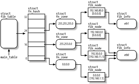
The main_table global variable points to an
fib_table object that represents the static
routing table of the IPS architecture. Actually, it is possible to
define secondary routing tables, but the table referenced by
main_table is the most important one. The
fib_table object includes the addresses of some
methods that operate on the FIB, and stores the pointer to a
fn_hash data structure.
The fn_hash data structure is essentially an array
of 33 pointers, one for every FIB zone. A
zone
includes routing information for
destination networks that have a given number of bits in the network
mask. For instance, zone 24 includes entries for networks that have
the mask 255.255.255.0.
Each zone is represented by a fn_zone descriptor.
It references, through a hash table, the set of entries of the
routing table that have the given netmask. For instance, in Figure 18-1, zone 16 references the entries 192.160.0.0
and 192.50.0.0.
The data relative to each routing table entry is stored in a
fib_node descriptor. A router might have several
entries, but it usually has very few network devices. Thus, to avoid
wasting space, the fib_node descriptor does not
include information about the network interface, but rather a pointer
to a fib_info descriptor shared by several
entries.
Looking up a route in the static routing
table is quite a slow task: the kernel has to walk the various zones
in the FIB and, for each entry in a zone, check whether the logical
AND between the host destination address and the
entry’s netmask yields the entry’s
exact network address. To speed up routing, the kernel keeps the most
recently discovered routes in a routing cache.
Typically, the cache includes several hundreds of entries; they are
sorted so that more frequently used routes are retrieved more
quickly. You can easily get the contents of the cache by reading the
/proc/net/rt_cache file.
The main data structure of the routing cache is the
rt_hash_table hash table; its hash function
combines the destination host’s IP address with
other information, like the source address of the packet and the type
of service required. In fact, the Linux networking code allows you to
fine tune the routing process so that a packet can, for instance, be
routed along several paths according to where the packet came from
and what kind of data it is carrying.
Each entry of the cache is represented by a rtable
data structure, which stores several pieces of information; among
them:
The source and destination IP addresses
The gateway IP address, if any
Data relative to the route identified by the entry, stored in a
dst_entryembedded in thertabledata structure (see the earlier section Section 18.1.5)
Another core component of the networking code is the so-called “neighbor cache,” which includes information relative to hosts that belong to the networks directly linked to the computer.
We know that IP addresses are the main host identifiers of the network layer; unfortunately, they are meaningless for the lower data-link layer, whose protocols are essentially hardware-dependent. In practice, when the kernel has to transmit a packet by means of a given network card device, it must encapsulate the data in a frame carrying, among other things, the hardware-dependent identifiers of the source and destination network card devices.
Most local area networks are based on the IEEE 802 standards, and in particular, on the 802.3 standard, which is commercially known as "Ethernet.”[118] The network card identifiers of the 802 standards are 48-bit numbers, which are usually written as 6 bytes separated by colons (such as “00:50:DA:61:A7:83”). There are no two network card devices sharing the same identifier (although it would be sufficient to ensure that all network card devices in the same local area network have different identifiers).
How can the kernel know the identifier of a remote device? It uses an IPS protocol named Address Resolution Protocol (ARP). Basically, the kernel sends a broadcast packet into the local area network carrying the question: “What is the identifier of the network card device associated with IP address X?” As a result, the host identified by the specified IP address sends an answer packet carrying the network card device identifier.
It is a waste of time and bandwidth to repeat the whole process for
every packet to be sent. Thus, the kernel keeps the network card
device identifier, together with other precious data concerning the
physical connection to the remote device, in the neighbor cache (often also called arp cache
).
You might get the contents of this cache by reading the
/proc/net/arp file. System administrators may
also explicitly set the entries of this cache by means of the
arp command.
Each entry of the neighbor cache is an object of type
neighbour; the most important field is certainly
ha, which stores the network card device
identifier. The entry also stores a pointer to a
hh_cache object belonging to the
hardware header cache
; since all packets sent to the same
remote network card device are encapsulated in frames having the same
header (essentially carrying the source and destination device
identifiers), the kernel keeps a copy of the header in memory to
avoid having to reconstruct it from scratch for every packet.
Each single packet transmitted through a network device is composed of several pieces of information. Besides the payload — that is, the data whose transmission caused the creation of the packet itself — all network layers, starting from the data link layer and ending at the transport layer, add some control information. The format of a packet handled by a network card device is shown in Figure 18-2.
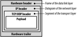
The whole packet is built by different functions in several stages. For instance, the UDP/TCP header and the IP header are composed of functions belonging, respectively, to the transport layer and the network layer of the IPS architecture, while the hardware header and trailer, which build the frame encapsulating the IP datagram, are written by a suitable method specific to the network card device.
The Linux networking code keeps each packet in a large memory area
called a socket buffer. Each socket buffer is
associated with a descriptor, which is a data structure of type
sk_buff that stores, among other things, pointers
to the following data structures:
The socket buffer
The payload — that is, the user data (inside the socket buffer)
The data link trailer (inside the socket buffer)
The INET socket (
sockobject)The network device’s
net_deviceobjectA descriptor of the transport layer header
A descriptor of the network layer header
A descriptor of the data link layer header
The destination cache entry (
dst_entryobject)
The sk_buff data structure includes many other
fields, like an identifier of the network protocol used for
transmitting the packet, a checksum field, and the arrival time for
received packets.
As a general rule, the kernel avoids copying data, but simply passes
the sk_buff descriptor pointer, and thus the
socket buffer, to each networking layer in turn. For instance, when
preparing a packet to send, the transport layer starts copying the
payload from the User Mode buffer into the higher portion of the
socket buffer; then the transport layer adds its TCP or UDP header
before the payload. Next, the control is transferred to the network
layer, which receives the socket buffer descriptor and adds the IP
header before the transport header. Eventually, the data link layer
adds its header and trailer, and enqueues the packet for
transmission.
[117] An alternative API between User Mode programs and networking code is provided by the Transport Layer Interface (TLI), introduced by System V Release 3.0. In general, TLI is implemented as a User Mode library that uses the STREAMS I/O subsystem. As mentioned in Section 1.1, the Linux kernel does not implement the STREAMS I/O subsystem.
[118] Actually, Ethernet local area networks sprang up before IEEE published its standards; unfortunately, Ethernet and IEEE standards disagree in small but nevertheless crucial details — for instance, in the format of the data link packets. Every host in the Internet is able to operate with both standards, though.