Technical Overview of L2F
This chapter focuses on in-depth troubleshooting of L2F. Fast and efficient troubleshooting requires a good knowledge of both L2F and its configuration, and to that end, a brief description of both follows.
As previously described, L2F is a protocol that allows the tunneling of PPP and SLIP frames across a IP backbone between a NAS and a Home Gateway. This chapter focuses on the tunneling of PPP frames because, to a great extent, PPP has superceded SLIP as the remote access protocol of choice.
The protocol itself uses the User Datagram Protocol (UDP), on top of which sits the L2F packet (header, payload, and optional CRC) itself.
Figure 2-2 illustrates the relationship between IP, UDP, and L2F.
Figure 2-2. Overall L2F Packet Format

Note that L2F packets utilize UDP port 1701. This will be relevant when troubleshooting L2F.
Now take a closer look at the L2F Protocol packet header itself in Figure 2-3.
The following list provides an analysis of the L2F header, starting with the header flags:
The F, K, S, and C bits, if set to 1, indicate that the optional fields (shown as opt in Figure 2-3) should be present:
- F, if set, indicates that the Offset field should be present.
- K, if set, indicates that the Key field should be present.
- S, if set, indicates that the Sequence number should be set.
- Finally, C, if set, indicates that the Checksum should be present.
The P bit, if set, indicates that this L2F packet is a priority packet. RFC 2341 does not specifically define what type of packet should constitute a priority packet but instead leaves this up to the implementer.
The Version (Ver) field is a 3-bit field and should be set to 001 binary = 1 decimal. No other value is valid, at least as far as L2F is concerned.
The 8-bit Protocol field has only three legal values, 0x01, 0x02, and 0x03. The value 0x1 indicates that this is an L2F management packet (type L2F_PROTO), the value 0x2 indicates that this packet contains PPP tunneled within L2F (type L2F_PPP), and the value 0x3 indicates that the packet contains SLIP tunneled within L2F (type L2F_SLIP).
Table 2-1 summarizes Protocol field values.
Table 2-1. L2F Protocol Field Values Value Type Description 0x00 L2F_ILLEGAL Illegal protocol type 0x01 L2F_PROTO Management packets 0x02 L2F_PPP Payload carries tunneled PPP 0x03 L2F_SLIP Payload carries tunneled SLIP If the value in the Protocol field specifies a management packet, then various options and suboptions are carried within the L2F payload. Options specify an overall message type, with suboptions carrying data associated with the message type.
Options and suboptions are discussed in the section “L2F Management Messages.”
The 8-bit Sequence field is present only if the S-bit is set. The S-bit must be set, and therefore, sequence numbering must be used, for L2F management packets.
RFC 2341 allows a degree of flexibility with regard to the Sequence number field. Packets other than management packets can use sequence numbers, but it is not mandatory. Some protocols might be sensitive to packets arriving out of sequence, and sequence numbering can be useful in this case. If sequence numbering is used, it must be present in every packet for a particular session (for every packet with the same multiplex ID [MID]).
The MID is a 16-bit field, and it is used to distinguish between different sessions (connections) within the overall L2F tunnel from a NAS to a Home Gateway.
Figure 2-4 illustrates an L2F tunnel between a NAS and Home Gateway with multiple sessions within it, each from a different remote access client.
In Figure 2-4, two remote access users are connected to the NAS. Their PPP connections are tunneled via L2F from the NAS to the Home Gateway.
The Home Gateway has to be able to distinguish between the two sessions, and this is done using unique MIDs. Remote access user A's PPP connection uses MID 17, and user B's PPP connection uses MID 18. Note that MID 17 and 18 have no special significance and are used purely for illustrative purposes.
The MID 0 is reserved for L2F management (L2F_PROTO) packets, leaving a theoretical 2^16-1 (65535) MIDs for client sessions.
The Client ID (CLID) is a 16-bit field, and it is used to uniquely identify a particular tunnel from a NAS to a Home Gateway and vice-versa. At any one time, a Home Gateway might be terminating L2F tunnels from a number of NASs. Similarly at any one time, a NAS might have tunnels to several Home Gateways. To allow the Home Gateway (or NAS) to distinguish between the packets coming through tunnels from different NASs (or Home Gateways), a CLID is used.
The CLID assigned to a particular tunnel is communicated during the tunnel setup. It is communicated via the Assigned CLID field in a L2F_CONF packet (see the section “L2F Tunnel Establishment”). The receiving device then uses the CLID to distinguish inbound packets belonging to different tunnels.
For example, a NAS with hostname LODI_NAS1 receives a call from an employee of the Perris Corporation. Having no existing L2F tunnel to the Home Gateway for the Perris Corporation (PERRIS_HGW1), LODI_NAS1 needs to set one up. Tunnel setup begins from LODI_NAS1 to PERRIS_HGW1. PERRIS_HGW1 is already terminating an L2F tunnel from LODI_NAS2, and this tunnel is identified by the CLID 1. PERRIS_HGW1 needs to distinguish inbound packets on the tunnel from LODI_NAS1 from those inbound from LODI_NAS2. During tunnel setup to LODI_NAS1, therefore, PERRIS_HGW1 assigns the unique CLID 2 and communicates this to LODI_NAS1 via the Assigned CLID field in a L2F_CONF message. Thereafter, whenever LODI_NAS1 needs to send L2F tunnel packets to PERRIS_HGW1, it puts the number 2 in the Client ID field.
In simple terms, during tunnel setup, PERRIS_HGW1 says to LODI_NAS1, “Whenever you want to send tunnel packets to me, please uniquely identify them with the CLID 2 so that I will know that they are packets from you.” Remember that this process is bidirectional, so LODI_NAS1 also communicates a locally unique CLID to PERRIS_HGW1.
Figure 2-5 illustrates this concept.
In Figure 2-5, PERRIS_HGW1 is receiving L2F tunnel packets from both LODI_NAS1 and LODI_NAS2. It is able to distinguish these packets by examining the CLID field.
The next field in the packet header is Length. The Length field is 16 bits long, and it reflects the length of the header and payload but does not include the checksum if one is present. The Offset field, if present, is used to specify how many bytes after the L2F header the payload starts.
For some transport architectures, it might be more efficient if the payload is aligned with a 32-bit boundary, and the Offset field can be used to ensure this (with an offset of 0). The Offset is present only if the F bit is set.
The Key is a 32-bit field, is only present if the K bit is set, and is used to authenticate a tunnel peer. This prevents tunnel packets from being spoofed by another source.
The Key is calculated as follows:
1. | During tunnel establishment, each end of the tunnel sends a challenge to its peer in an L2F_CONF message. |
2. | This challenge contains a random number. The recipient of this challenge calculates a 128-bit hash value based on the random number and a shared password (tunnel secret). |
3. | The recipient then breaks the 128-bit hash into four parts, exclusive-ORs (XORs) them together, and sends the resultant hash value in the Key field back to its tunnel peer (NAS or Home Gateway). Note that the original 128-bit hash value is also sent to the tunnel peer during tunnel authentication. |
4. | The originator of the challenge calculates its own hash value based on the same random number and the shared password and compares it to the hash value received. If the two hash values match, authentication is successful. |
The 32-bit Key, once calculated, is carried in all tunnel packets for the duration of its lifetime.
Next in the packet comes the L2F payload. This is used to carry either L2F management messages or PPP frames depending on the packet type.
Finally, if the C bit is set, a 16-bit checksum is appended to the packet. The checksum is calculated over the entire L2F packet, starting with the header and including the payload.
L2F Management Messages
As previously mentioned, if the L2F header has a value of 0x01 (L2F_PROTO) in the Protocol field, the packet is a tunnel management packet. Within the payload of a tunnel management packet, various options and suboptions can be carried. The option specified dictates what kind of management message the packet is, whereas the suboptions carry any data associated with that particular message type.
Table 2-2 summarizes the available options and their corresponding suboptions.
| Option | Suboption | Suboption Value | Description |
|---|---|---|---|
| L2F_CONF (0x01) | L2F_CONF_NAME | 0x02 | Name of peer sending L2F_CONF |
| L2F_CONF_CHAL | 0x03 | Random number challenge | |
| L2F_CONF_CLID | 0x04 | Assigned CLID for peer use | |
| L2F_OPEN (0x02) | L2F_OPEN_NAME | 0x01 | Username received from remote access client |
| L2F_OPEN_CHAL | 0x02 | Challenge Handshake Authentication Protocol (CHAP) challenge sent by NAS to remote access client | |
| L2F_OPEN_RESP | 0x03 | 1. Tunnel authentication response 2. Response from remote access client to NAS challenge (hash value, if CHAP) | |
| L2F_ACK_LCP1 | 0x04 | Last LCP CONFACK received from remote access client by NAS | |
| L2F_ACK_LCP2 | 0x05 | Last LCP CONFACK sent by NAS to remote access client | |
| L2F_OPEN_TYPE | 0x06 | Type of authentication used | |
| L2F_OPEN_ID | 0x07 | ID associated with CHAP challenge | |
| L2F_REQ_LCP0 | 0x08 | First LCP CONFREQ received from remote access client | |
| L2F_CLOSE (0x03) | L2F_CLOSE_WHY | 0x01 | Reason code for close |
| L2F_CLOSE_STR | 0x02 | ASCII string description of close reason | |
| L2F_ECHO (0x04) | (no suboptions) | Keepalive | |
| L2F_ECHO_RESP (0x05) | (no suboptions) | Response to L2F_ECHO |
As you can see, if a L2F_CONF message is sent, three suboptions can be carried along with it: L2F_CONF_NAME, L2F_CONF_CHAL, and L2F_CLID. Similarly, if the message is an L2F_OPEN, the suboptions that can be carried range from L2F_OPEN_NAME to L2F_REQ_LCP0. When an L2F_CLOSE message is sent, the two suboptions can be carried are L2F_CLOSE_WHY and L2F_CLOSE_STR. Finally, if the message is either an L2F_ECHO or an L2F_ECHO_RESP, no suboptions can be carried.
The sections that follow describe the function of the options and suboptions in greater detail.
L2F Tunnel Establishment
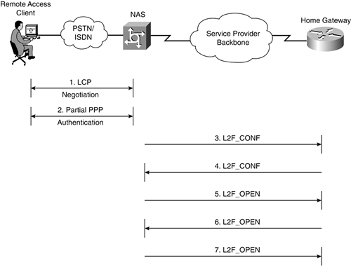
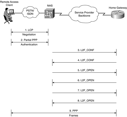
Tunnel establishment begins with the reception of a PPP connection by the NAS. At this stage, the NAS goes through the Link Control Protocol (LCP) negotiation phase with the remote client, with options such as compression, callback, and authentication protocol being negotiated.
As soon as the LCP negotiation phase has been completed, the NAS and the remote client move onto authentication. A Challenge Handshake Authentication Protocol (CHAP) challenge is now sent by the NAS to the client. Note that although either CHAP or Password Authentication Protocol (PAP) could be used for authentication, this chapter assumes that CHAP is used.
Upon receipt of the CHAP challenge, the remote client takes the random number in the challenge (call it Random3), the Challenge ID, and the CHAP password and calculates a Message Digest 5 (MD5) hash value (call it Hash3). This hash value is transmitted back to the NAS via a CHAP response message.
At this point, the NAS performs a partial authentication on the CHAP response. The NAS does not examine the hash value contained within the CHAP response packet as it normally would but looks at the sender's name (which is also contained within the response). If this PPP connection is one that should be tunneled to a Home Gateway, the sender's name should be in the format username@domain_name. The domain name indicates to the NAS to which Home Gateway this PPP connection should be tunneled.
It is worth noting that this delimiter character (@) can be modified on the NAS using the command vpdn domain-delimiter.
This association of user to tunnel can also be based on the Dialed Number Information Service (DNIS) string. The DNIS is the dialed number, and it is present in ISDN Q.931 messages passed from the ISDN switch to the NAS during call setup. This means that, for example, if a remote access client dials the number 555-1234 to access the NAS, the NAS will use this number to associate the user to a L2F tunnel.
The user-to-tunnel association can also be established on a per-username basis. In this case, the NAS sends the complete username to an authentication, authorization, and accounting (AAA) server, and the AAA server responds with tunnel information based on this username. Configuration of per-user VPDN is beyond the scope of this chapter, but more details can be found at the following URL:
http://www.cisco.com/en/US/tech/tk801/tk703/technologies_configuration_example09186a0080094860.shtml
Once the user-to-tunnel association has been made, the NAS either initiates tunnel setup to the appropriate Home Gateway, or if a tunnel already exists, initiates a new L2F session for the PPP connection within that tunnel.
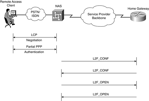
In this example, assume that the tunnel is not yet in existence. The NAS initiates tunnel setup by sending a L2F_CONF message. Figure 2-6 illustrates the L2F_CONF sent by the NAS to the Home Gateway.
Figure 2-6. L2F_CONF Sent by the NAS

Within the L2F packet header, the protocol type field is set to 0x01 (L2F_PROTO), which indicates that this is a management message. The Sequence Number, MID, CLID, and Key are all set to a value of 0. Contained within the payload is the L2F_CONF (option 0x01) itself.
The L2F_CONF message contains within it the following suboptions:
L2F_CONF_NAME (name of the tunnel initiating NAS)
L2F_CONF_CHAL (random number challenge)
L2F_CONF_CLID (assigned Client ID)
In this example, assume that the NAS has chosen an assigned CLID of 34 (which is locally unique to the NAS).
Figure 2-7 represents this packet.
Figure 2-7. L2F_CONF Message Sent by the NAS

Notice that a checksum is omitted in this example.
The receiving Home Gateway first confirms that the incoming L2F_CONF message is from a recognized NAS. If it is, the Home Gateway takes the random number specified in L2F_CONF_CHAL (call it Random1) and the tunnel secret (password) corresponding to the NAS's name (specified in L2F_CONF_NAME suboption) and performs a hash.
The password corresponding to the NAS's name is stored either locally on the Home Gateway (username nas_name password password) or on an authentication server (for example, a Remote Authentication Dial-In User Service [RADIUS] server).
If the L2F_CONF is not from a recognized NAS, the Home Gateway terminates tunnel setup.
Once the L2F_CONF has been accepted, the Home Gateway is ready to reply to the NAS. At this point, the Home Gateway responds to the NAS with its own L2F_CONF message. This serves as recognition of the NAS's tunnel setup request.
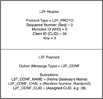
Figure 2-8 illustrates the L2F_CONF sent by the Home Gateway.
Within the L2F header, the protocol field is set to 0x01 (L2F_CONF); the Sequence Number, MID, and Key are all set to a value of 0; and the Client ID is set to 34 (the Assigned CLID from the NAS).
The L2F_CONF message itself is contained within the payload of the L2F packet. Again, a number of suboptions are included:
The L2F_CONF_NAME is set to be the name of the Home Gateway.
L2F_CONF_CHAL contains a random number (call it Random2).
L2F_CONF_CLID contains a CLID assigned by and locally unique on the Home Gateway (in this example, the value 38).
Figure 2-9 illustrates this packet.
Figure 2-9. L2F_CONF Message Sent by the Home Gateway
The Home Gateway has now received a L2F_CONF from the NAS, and the NAS has received a L2F_CONF from the Home Gateway.
The NAS now prepares to reply to, and to be authenticated by, the Home Gateway. To do this, the NAS calculates a hash (a CHAP-like hash) based on the random number, Random2, received from the Home Gateway in its L2F_CONF (see Figure 2-9), together with the tunnel secret (password). Call this hash Hash2, because it corresponds to Random2.
The NAS uses an L2F_OPEN message to communicate the resultant hash value, Hash2, to the Home Gateway.
Figure 2-10 shows the L2F_OPEN sent by the NAS.
The packet header for this message is constructed as follows:
The Protocol field contains the value 0x01.
The Sequence field (number) is set to 1 (the next exchange in the sequence, following the exchange of L2F_CONF messages).
The MID field is set to 0.
The CLID is set to 38 (the CLID assigned by the Home Gateway).
The Key is set to the value “Hash2” (32-bit).
The payload of the packet contains the L2F_OPEN message itself and suboption L2F_OPEN_RESP. The L2F_OPEN_RESP contains the entire 128-bit authentication hash value.
Figure 2-11 shows the L2F_OPEN message sent by the NAS.
Figure 2-11. The L2F_OPEN Message Sent by the NAS

Upon receipt of the L2F_OPEN message, the Home Gateway authenticates the NAS. This is done by comparing the received hash value (Hash2) to a hash value calculated locally based on the same input values (Random2 and the tunnel password). If the hash values match, the Home Gateway authenticates the NAS. If the values do not match, then tunnel setup is terminated.
Once it has authenticated the NAS, the Home Gateway sends an L2F_OPEN message to the NAS with Hash1 (hash computed on Random1, plus the tunnel secret) being carried in the packet.
Figure 2-12 illustrates the L2F_OPEN sent by the Home Gateway.
Figure 2-12. L2F_OPEN Sent by the Home Gateway
The packet format is shown in Figure 2-13, and is exactly the same as the L2F_OPEN sent by the NAS to the Home Gateway, with the protocol field set to 0x01 (L2F_PROTO), the Sequence Number set to 1, the MID is set to 0, and the CLID is set to 34 (the CLID assigned by the NAS). The Key is set to be hash1 (32-bit). Finally, the payload of the packet carries the message type itself (L2F_OPEN), with suboption L2F_OPEN_RESP.
Figure 2-13. Packet Format of the L2F_OPEN Sent by the Home Gateway to the NAS

The NAS compares the received hash value (hash1) to its own hash value calculated based on the same inputs (Random1 and the tunnel password). If the two hash values match, the NAS authenticates the Home Gateway. If not, the NAS terminates tunnel setup.
Assuming that the NAS successfully authenticates the Home Gateway, both ends of the tunnel have now authenticated each other and are now ready to move on to the establishment of L2F sessions within the tunnel.
L2F Session Establishment
Now that the L2F tunnel has been established between the NAS and the Home Gateway, the NAS can proceed to pass the LCP and authentication data negotiated with the remote access client to the Home Gateway.
You'll remember that when the client first dialed into the NAS, the NAS issued a CHAP challenge to the client. Within the challenge was an ID value, together with a random number (Random3). The client responded to the challenge with a hash value (call it hash3) calculated from the random number (Random3), the ID, and the secret password.
Although the NAS issued the CHAP challenge, it cannot fully authenticate the client because it does not have the password. In fact, the logical endpoint of the PPP connection is responsible for authenticating the client, and that is the Home Gateway.
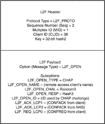
The NAS needs to pass the hash value, hash3, together with the client's user name and the CHAP challenge ID value on to the Home Gateway. To do this, it sends another L2F_OPEN message.
Figure 2-14 shows the session setup L2F_OPEN sent by the NAS.
Figure 2-14. Session Setup L2F_OPEN Sent by the NAS
The L2F_OPEN message header takes the following form:
The Protocol field contains the value 0x01 (because this is still a tunnel management message).
The Sequence number field is set to the value 2 (this is the next in the sequence).
The MID field is set to 1.
The CLID is set to 38.
The Key is set to the value Hash2.
The payload contains the message type (option) L2F_OPEN. A number of suboptions are included:
L2F_OPEN_TYPE (indicating authentication type)
L2F_OPEN_NAME (the remote access client's username)
L2F_OPEN_CHAL (the random number used to challenge the client [Random3])
L2F_OPEN_RESP (the hash value received in the response, Hash3)
L2F_OPEN_ID (the ID used in the challenge from the NAS to the client).
In addition to client authentication information, the NAS passes some client LCP negotiation messages to the Home Gateway:
The last LCP Configure-Ack (CONFACK) sent from the remote access client to the NAS (L2F_ACK_LCP1)
The last CONFACK sent from the NAS to the client (L2F_ACK_LCP2)
The first Configure-Request (CONFREQ) sent from the client to the NAS (L2F_REQ_LCP0).
LCP negotiation messages passed by the NAS to the Home Gateway can allow the Home Gateway to much more rapidly configure LCP for communication with the client. If it accepts the options in the CONFACKs, there is no need to renegotiate with the client. However, the Home Gateway can renegotiate LCP with the client if it so wishes.
LCP renegotiation can be based on the options specified in the first CONFREQ sent by the client but not agreed to by the NAS.
It is worth noting that the MID value has now changed from 0 to a nonzero value. This is because this message corresponds to the L2F session, rather than being a purely tunnel management message (which would have a MID value of 0). Note that MID values are assigned based on being the next available.
Figure 2-15 illustrates this L2F_OPEN message.
Upon receiving this L2F_OPEN message, the Home Gateway responds to the NAS with a L2F_OPEN. This L2F_OPEN serves to confirm acceptance of the client L2F session.
Figure 2-16 shows the L2F_OPEN sent from the Home Gateway to the NAS.
Figure 2-16. L2F_OPEN from the Home Gateway to the NAS

The L2F_OPEN message header takes the following format:
The Protocol field is set to 0x01 (L2F_PROTO).
The Sequence number field is set to 2.
The MID is set to 1.
The CLID is set to 34.
The Key is set to Hash1.
The payload of the packet contains the L2F_OPEN message itself. Figure 2-17 illustrates this packet.
Figure 2-17. Session L2F_OPEN Message

The NAS, having received this acceptance message from the Home Gateway, begins to transparently forward PPP frames between the client and the Home Gateway.
Figure 2-18 shows the forwarding of PPP frames between the Home Gateway and the remote access client.
Figure 2-18. NAS Forwards PPP Frames
It is worth qualifying the statement word transparently. PPP frames are unescaped, and any bit-stuffing is removed before forwarding. Additionally, PPP flags (excluding the address and control flags, unless negotiated away) and the CRC are omitted.
PPP frames (from the remote access client) forwarded by the NAS to the Home Gateway are tunneled within L2F_PPP packets. This means that the packet headers now take the following form:
The Protocol field is set to 0x02 (L2F_PPP, indicating PPP in payload).
The sequence number is set to 0 (assuming that sequence numbering is not used).
The MID is set to 1; the CLID is set to 38.
The Key is set to Hash2.
The payload contains the PPP frame.
Similarly, PPP frames forwarded by the Home Gateway to the NAS are carried in L2F_PPP packets, with the packet header constructed as follows:
The Protocol field is set to 0x02.
The Sequence Number is set to 0; the MID is set to 1.
The CLID is set to 34.
The Key is set to Hash1.
The payload again contains the PPP frame.
Note how the Sequence number is now 0 for PPP frames sent between the NAS and the Home Gateway. This is because it is mandatory only for tunnel management packets to contain sequence numbering.
Figure 2-19 illustrates the form of PPP frames tunneled within L2F packets sent from the NAS to the Home Gateway.
Figure 2-19. L2F_PPP Packets Sent by the NAS

Figure 2-20 shows the form taken by PPP frames tunneled from the Home Gateway to the NAS.
Figure 2-20. L2F_PPP Packets Sent by the Home Gateway

L2F Tunnel Maintenance
RFC 2341 specifies a keepalive mechanism for L2F tunnels. This consists of sending L2F_ECHO and L2F_ECHO_RESP messages. The L2F_ECHO is not a mandatory requirement for an implementation of L2F, but should an L2F peer receive an L2F_ECHO message, it is mandatory that the peer replies with a L2F_ECHO_RESP.
Figure 2-21 illustrates the L2F keepalive mechanism.
Figure 2-21. L2F Keepalive Mechanism

A recommended practice is that if a tunnel peer (NAS or Home Gateway) transmits at least five consecutive L2F_ECHOs without receiving a L2F_ECHO_RESP in reply, it (the NAS or Home Gateway) should assume that its peer has terminated the tunnel connection.
The L2F_ECHO is encoded as option 0x04, with the MID set to 0 (tunnel management packet). It is possible for L2F to include extra data in the payload, and if extra data is present, it must be preserved in the L2F_ECHO_RESP (option 0x05). A possible usage of this extra data is to associate an L2F_ECHO_RESP with a particular L2F_ECHO.
Figure 2-22 represents the L2F_ECHO.
Figure 2-22. L2F_ECHO Message

Figure 2-23 illustrates the L2F_ECHO_RESP.
Figure 2-23. L2F_ECHO_RESP Message

You will notice that the nonzero sequence numbering in the L2F_ECHO and L2F_ECHO_RESP. This is because, as L2F management messages, these two messages must carry sequence numbering.
The Key values carried in the L2F_ECHO and L2F_ECHO_RESP messages are the same as those calculated in the tunnel establishment phase (Hash1 or Hash2). Similarly, the CLID corresponds to the CLIDs assigned during tunnel establishment.
L2F Tunnel Teardown
The final action in the life of tunnel is, of course, termination. Tunnel termination can be caused by several factors, for example reception of an invalid message type, reception of a PPP TERMREQ (Termination Request) on the last PPP connection in a tunnel, or simply execution of the command clear vpdn tunnel.
It is worth pointing out that the reception of packets with an invalid key will not cause the tunnel to be terminated. The fact that L2F tunnels are not terminated when packets with an invalid key are received prevents denial-of-service attacks against L2F tunnels.
Once an event that mandates tunnel teardown has occurred, the endpoint wishing to tear down the tunnel (either the NAS or the Home Gateway) transmits an L2F_CLOSE message to its peer.
Figure 2-24 illustrates the L2F_CLOSE message.
Figure 2-24. NAS Sends an L2F_CLOSE Message

Figure 2-25 illustrates the format of the L2F_CLOSE message.
Figure 2-25. L2F_CLOSE Message Format

The L2F_CLOSE_WHY suboption, which can optionally be included in the L2F_CLOSE message, is 4 octets long. It is used to inform the NAS of the reason for a tunnel setup failure or tunnel termination. An implementer might choose not to indicate the reason for declining certain tunnels. This helps to prevent attackers from gaining valuable information that would help them to progress their attacks.
The reason for tunnel or session setup failure is encoded in suboption L2F_CLOSE_WHY (0x01), as per Table 2-3.
| L2F_CLOSE_WHY Failure Reason | Failure Code |
|---|---|
| Authentication failure | 0x00000001 |
| Out of resources | 0x00000002 |
| Administrative intervention | 0x00000004 |
| User quota exceeded | 0x00000008 |
| Protocol error | 0x00000010 |
| Unknown user | 0x00000020 |
| Incorrect password | 0x00000040 |
| PPP configuration incompatible | 0x00000080 |
| Wrong multilink PPP destination | 0x00000100 |
| Carrier loss | 0x00000200 |
| User disconnect | 0x00000400 |
| PPP disconnect | 0x00000800 |
| Tunnel shutdown | 0x00001000 |
| Session limit / Softshut | 0x00002000 |
| No sessions | 0x00004000 |
Additionally, L2F_CLOSE_WHY failure codes that can be masked by the value 0xFF000000 (0x01000000 to 0xFF000000) are reserved for vendor-specified codes.
The L2F_CLOSE_STR suboption can also be included in the L2F_CLOSE message. This is an ASCII string that describes the reason for the tunnel termination.
