Technical Overview of IPSec
When troubleshooting IPSec VPNs, it is very important to have a good understanding of the underlying mechanisms used to establish the IPSec tunnel and transport the traffic over it. To that end, a brief discussion of the IPSec architecture is included here.
The IPSec architecture (defined in RFC 2401) provides security services to IP traffic. These security services include integrity, data origin authentication, replay protection, data confidentiality, and limited traffic flow confidentiality.
IPSec components that provide these services include the following:
Security protocols
Security associations
Key management mechanisms
Associated authentication and encryption algorithms
The remainder of this section describes the first three components in greater detail. Authentication and encryption algorithms are discussed further in the sections “Security Protocols” on page 656 and “Configuring IPSec VPNs” on page 668.
Security Protocols
IPSec provides two security protocols that provide traffic security services to IP traffic transiting between IPSec peers:
Authentication Header (AH)
Encapsulating Security Payload (ESP)
Authentication Header
Authentication Header (AH) is a packet header that can provide message integrity, origin authentication, and, optionally, replay protection.
Message integrity and origin authentication (collectively called authentication) employ algorithms such as one-way hash functions to ensure that messages are not modified in transit and are sent by the supposed originator and not any other source. Hash functions that can be employed include Message Digest 5 (MD5) and the Secure Hash Algorithm (SHA-1).
Authentication protects the IP header (with exception of fields, such as Time-To-Live [TTL], that might change in transit), as well as the packet payload.
Replay protection ensures that messages are not re-sent by other malicious sources. Replay protection is implemented using a sequence number.
AH is identified in the preceding packet header by IP protocol number 51 and can operate in one of two modes:
Transport mode
Tunnel mode
AH Transport Mode
In transport mode, the AH is inserted into an IP packet between original IP header and the packet payload (including the UDP/TCP/other header).
Transport mode encapsulation is illustrated in Figure 8-3.
Figure 8-3. AH Transport Mode Encapsulation
Transport mode is used to protect traffic between end systems.
AH Tunnel Mode
In tunnel mode, a new IP header and AH are prepended to the original IP packet. The new header is used to transport the original packet between security gateways such as routers or firewalls.
Figure 8-4 illustrates tunnel mode encapsulation.
Figure 8-4. AH Tunnel Mode Encapsulation
Tunnel mode can be used between end systems, but is typically used to protect traffic transiting security gateways between end systems. AH can be used either on its own or in conjunction with ESP.
For more information about AH, see RFC 2402.
Encapsulating Security Payload
Encapsulating Security Payload (ESP) is a packet header with trailers that can provide message integrity, data origin authentication, confidentiality, antireplay protection, and traffic flow confidentiality.
Message integrity and authentication (collectively called authentication) perform the same functions and use the same algorithms as described in the previous section on AH. One key difference, however, is that ESP does not offer authentication of the initial IP header.
Confidentiality consists of packet encryption using algorithms such as the Data Encryption Standard (DES), Triple DES (3DES), and the Advanced Encryption Standard (AES).
Replay protection again ensures that messages are not replayed by another malicious source. Replay protection is implemented using sequence numbers.
Traffic flow confidentiality prevents traffic analysis, ensuring that eavesdroppers cannot discover information such as the volume, frequency, or packet sizes of traffic sent between any given source and destination. Traffic flow confidentiality is available only in tunnel mode.
ESP is identified in the preceding packet header by IP protocol number 50 and can operate in one of two modes:
Transport mode
Tunnel mode
ESP Transport Mode
In transport mode, an ESP header is inserted into an IP packet between the original packet header and the payload (including the UDP/TCP/other header). A trailer consisting of padding can also be added if required by the encryption algorithm. Finally, authentication data can be appended to the packet. This authentication data consists of an Integrity Check Value (ICV), which is calculated over the ESP packet.
Figure 8-5 illustrates transport mode encapsulation.

Transport mode is used to protect traffic between end systems.
ESP Tunnel Mode
In tunnel mode, a new IP header and ESP header are prepended to the original IP packet. Additionally, a trailer and authentication data may be added to the packet. The new IP header is used to transport the original packet between security gateways.
Figure 8-6 illustrates tunnel mode encapsulation.

Tunnel mode can be used to protect traffic sent between end systems, but it is typically used to protect traffic transiting security gateways between end systems.
See RFC 2406 for more details on ESP.
Security Associations
An IPSec security association (SA) is a protected connection between two end systems or security gateways, and it is unidirectional in nature. This means that for secure communication to be established between two entities, there must be at least one SA in each direction.
An SA is uniquely identified by a combination (triple) of a unique 32-bit number called a Security Parameter Index (SPI), together with a destination address and security protocol (either AH or ESP).
RFC 2401 defines two database structures, known as the Security Policy Database (SPD) and the Security Association Database (SAD or SADB).
The SPD contains IPSec policy definitions, and it is used during the processing of all inbound and outbound traffic. The SPD defines traffic that should be dropped, traffic that should be protected by IPSec, and traffic that should not protected by IPSec.
If, during traffic processing, the SPD determines that there is inbound traffic that should be protected by IPSec, but there is no SA in the SABD, that traffic will be dropped. Also, if the SPD determines that there is outbound traffic that should be protected by IPSec, but there is no SA in the SADB, this will trigger the Internet Key Exchange (IKE) protocol to negotiate the required SA with the appropriate IPSec peer.
The SADB, on the other hand, is used to store parameters associated with SAs, including information such as the SPI, algorithms, and the key. The SADB is populated either manually or dynamically via IKE negotiation.
SA and Key Management with the IKE Protocol
The IKE protocol version 1, defined in RFC 2409, provides an automated mechanism for the exchange of keying material and secure negotiation of IPSec SAs. It is also possible to manually configure keying material and SAs on IPSec peers. Manual configuration of keying material and SAs is practical only in very small-scale environments, however, so it is not discussed further in this section.
IKE is a hybrid protocol made up of elements of the following protocols:
NOTE
Additional elements are defined in RFC 2407 (“The Internet IP Security Domain of Interpretation for ISAKMP”).
IKE operates in two phases and three modes:
Phase 1— Main or aggressive mode negotiation is used in this phase to establish a single bidirectional IKE SA between IPSec peers. This IKE SA, in turn, provides a secure means by which IPSec SAs can be established via quick mode negotiation.
Phase 2— Quick mode negotiation occurs during this phase.
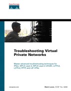
Overall ISAKMP Message Format
As previously mentioned, one element of IKE is ISAKMP, which provides (among other things) a message format for IKE negotiation.
To understand IKE negotiation, it is important to have a basic understanding of the overall structure of the ISAKMP message, which is made up of a fixed header and a number of payloads. Figure 8-7 illustrates the relationship of the header to the payloads.
Figure 8-7. Overall ISAKMP Message Format

In Figure 8-7, the sample message consists of a header and four payloads. Each payload is indicated in the previous payload. For example, in the header, the Next Payload field indicates that the first payload in the chain is type X1. The Next Payload field in the X1 payload indicates that the second payload is of type X2, and so on. The final payload is indicated by the fact that the Next Payload field contains a value of 0.
Table 8-1 lists the payload types, together with their associated functions.
| Value | Payload Type | Description |
|---|---|---|
| 0 | NONE | This is the final payload |
| 1 | Security Association (SA) | Contains security attributes ([sub] payload types 2 and 3) |
| 2 | Proposal (P) | Contains information used during SA negotiation |
| 3 | Transform (T) | Contains information used for SA negotiation (for example, IKE policy information) |
| 4 | Key Exchange (KE) | Used for key exchange between peers |
| 5 | Identification (ID) | Used to exchange identification information between peers |
| 6 | Certificate (CERT) | Used to send certificates or certificate-related information |
| 7 | Certificate Request (CR) | Used to request certificates |
| 8 | Hash (HASH) | Used to exchange data generated by hash function |
| 9 | Signature (SIG) | Used to exchange data generated by digital signature function (for nonrepudiation) |
| 10 | Nonce (NONCE) | Contains random data used to indicate liveliness and to protect against replay attacks |
| 11 | Notification/Notify (N) | Used to send informational data such as error conditions |
| 12 | Delete | Used to communicate SPIs of deleted SAs to peer |
| 13 | Vendor ID (VID) | Constant value to identify a vendor; can be used to implement vendor-specific features |
| 14–127 | RESERVED | Must be set to 0 |
| 128–255 | Private Use | Private use |
| For more information on ISAKMP message structures, see RFC 2408. | ||
IKE Phase 1
As previously mentioned, the objective of IKE phase 1 is to establish a secure IKE SA and generate keys for IPSec. To this end, IPSec peers must agree on IKE parameters, exchange keying material, and authenticate each other.
These objectives are achieved using one of the following negotiation modes:
Main mode negotiation
Aggressive mode negotiation
NOTE
Before Cisco IOS Software Release 12.2(8)T, Cisco routers could not initiate aggressive mode negotiation.
Main Mode Negotiation
Main mode negotiation involves the exchange of six messages between IPSec peers. The precise form of these messages is dictated by the method of peer authentication used.
The three methods of authentication that can be used with IKE (in both main and aggressive modes) are:
Preshared keys
Rivest, Shamir, Adleman (RSA) signatures
RSA encrypted nonces
NOTE
Because authentication using encrypted nonces is not widely used, this section concentrates on authentication using preshared keys and RSA signatures.
Main Mode with Preshared Key Authentication
As mentioned, main mode consists of the exchange of three pairs or six messages between IPSec peers. Each of these pairs of messages serves a particular purpose.
When a router or other system (called the initiator) wants to begin IKE negotiation, it sends a message to its peer. This message contains one or more IKE policy proposals (protection suites) containing parameters such as encryption algorithm, hash algorithm, authentication method, Diffie-Hellman group, and SA lifetime. These policy proposals are contained within an SA payload and its associated Proposal and Transform payloads. IKE policy is configured on Cisco routers using the crypto isakmp policy command.
The peer router (called the responder) examines the IKE policy information and attempts to find a match with its own locally configured IKE policies. Assuming the responder finds a matching IKE policy, it responds with a message indicating acceptance of one of the initiator's policies. Again, this proposal is contained with an SA payload. The peers have now negotiated an IKE policy.
The next two messages sent between the initiator and responder serve to exchange Diffie-Hellman public values, as well as nonces (random numbers). These values are exchanged in KE and NONCE payloads, respectively (see Table 8-1).
Diffie-Hellman is a public key algorithm that allows peers to exchange public key values over an insecure network, to combine the value received with their own private value, and through the wonders of modular exponentiation, to arrive independently at the same shared secret key.
The two nonce values (initiator's and responder's), together with the preshared key, are then used to generate the first of four session key values (SKEYID).
SKEYID is used, together with the shared secret key (from the Diffie-Hellman exchange) and other keying material, to derive three other session key values called SKEYID_d, SKEYID_a, and SKEYID_e. These session key values are used to derive keys for IPSec, authenticate further ISAKMP messages, and encrypt ISAKMP messages respectively.
At this stage, an IKE policy has been agreed upon (first two messages), keying material has been exchanged (second two messages), and session key values have been calculated.
All that now remains in phase 1 is for the two peers to exchange hash and identification values, contained in HASH and ID payloads. This is done during a third exchange of messages.
The peers then authenticate each other based on the hash values received. If the received hash value is the same as a hash value calculated locally, authentication succeeds. Note that the function of the ID payload is to identify the sender using, in this case, an IP address. The third exchange in phase 1 is encrypted (using SKEYID_e).
Figure 8-8 illustrates IKE phase 1 using preshared keys.
Figure 8-8. IKE Phase 1 Using Preshared Keys

Main Mode with RSA Signature Authentication Using Digital Certificates
Main mode negotiation with RSA signature (digital certificate) authentication is very similar to main mode with preshared key authentication. The first two messages are again used to negotiate an IKE policy. The second two messages are again used to exchange keying material (Diffie-Hellman public values and nonces).
The difference is the third exchange of messages. IKE peers using RSA signature authentication exchange identification, certificates, and signature. These elements are carried in the ID, CERT, and SIG payloads respectively.
Note that the SIG (signature) payload contains a digital signature. This provides nonrepudiation, which means that the system that sent the message cannot deny that it sent the message. The ID payload can contain the system's IP address, a fully qualified domain name (FQDN), or an X.500 distinguished name, for example.
Figure 8-9 illustrates main mode with RSA signature authentication using digital certificates.
Figure 8-9. Main Mode with RSA Signature Authentication

Aggressive Mode Negotiation
Aggressive mode is faster but slightly less secure than main mode negotiation. It is faster because negotiation consists of only three messages, and it is slightly less secure because the ID payload is exchanged unencrypted.
Aggressive Mode with Preshared Key Authentication
The first message sent by the initiator in aggressive mode consists of proposed IKE policies, its Diffie-Hellman public value, a nonce value, and identification. These are contained in the SA, KE, NONCE, and ID payloads, respectively. Note that all payloads exchanged during aggressive mode perform the same function as in main mode.
The responder now replies with a message containing the accepted IKE policy, its Diffie-Hellman public value, a nonce, a hash used by the initiator to authenticate the responder, and identification. These are contained in SA, KE, HASH, and ID payloads.
Finally, the initiator sends the third and final message in the exchange. This consists simply of a hash (used by the responder to authenticate the initiator). The hash is contained in a HASH payload.
Figure 8-10 illustrates aggressive mode using preshared key authentication.
Figure 8-10. Aggressive Mode Using Preshared Key Authentication

Aggressive Mode with RSA Signature Authentication Using Digital Certificates
Aggressive mode with RSA signature (digital certificate) authentication follows a similar pattern to that for preshared keys, with three messages being exchanged.
The first message sent by the initiator contains policy proposals, its Diffie-Hellman public value, a nonce value, and identification. These are contained in SA, KE, NONCE, and ID payloads, respectively.
The responder replies with a message containing the accepted policy, its Diffie-Hellman public value, a nonce, identification, its certificate, and signature. These are contained in SA, KE, NONCE, ID, CERT, and SIG payloads.
Finally, the initiator sends a certificate and signature. These are contained in CERT and SIG payloads.
Figure 8-11 illustrates aggressive mode with RSA signature authentication using digital certificates.
Figure 8-11. Aggressive Mode with RSA Signature Authentication

IKE Phase 2
Once phase 1 is complete, and the IKE SA has been established, phase 2 can begin. The objective of phase 2 is to negotiate IPSec SAs.
There is only one mode of negotiation within phase 2, called quick mode. Note that quick mode negotiation is protected by the IKE SA established in phase 1 (using SKEYID_a and SKEYID_e). Quick mode negotiation consists of the exchange of three messages between the initiator and the responder.
The first message in the exchange contains a hash, IPSec proposals, a nonce, and optionally, another Diffie-Hellman public value, and identities. These elements are contained in HASH, SA, NONCE, KE, and ID payloads, respectively.
The hash is used to authenticate the message to the responder. The IPSec proposals are used to specify security parameters, such as the security protocol (AH or ESP), encryption algorithm, hash algorithm, and IPSec tunnel mode (transport or tunnel) to be used for the IPSec SA. These parameters are configured on Cisco routers using the crypto ipsec transform-set command.
The nonce is used to protect against replay attacks. It is also used as additional keying material. The Diffie-Hellman public value is included in the message only if the initiator is configured for Perfect Forward Secrecy (PFS). Normally, keys used with IPSec SA are derived from keying material generated during IKE phase 1. This means that IPSec keys generated using PFS are more secure. PFS is configured using the set pfs {group 1 | group 2} command (within the crypto map).
Phase 2 identities are used to exchange selector information. These identities describe the addresses, protocols, and ports for which this IPSec SA is being established. On Cisco routers, phase 2 identities are configured using a crypto access list.
The responder then replies with a message containing a hash (used by the initiator to authenticate the responder), an IPSec proposal acceptance, a nonce value, and optionally, a Diffie-Hellman public value (if the responder supports PFS), and identities. These elements are again contained in HASH, SA, NONCE, KE, and ID payloads. The payloads in the message sent by the responder serve the same purpose as those sent by the initiator.
The initiator now sends a third and final message. This contains a hash (HASH payload), and it serves to acknowledge the responder's message and to prove that the initiator is alive (that is, that the first message sent by the initiator was not just a message replayed by another source).
Figure 8-12 illustrates quick mode negotiation.
Figure 8-12. Quick Mode Negotiation