Case Studies
This section contains solutions for issues not covered in the main troubleshooting section of this chapter.
Figure 4-30 illustrates the topology used in Case Studies 1 through 4.
Figure 4-30. Topology for Case Studies 1 Through 4

The RADIUS server used in Case Studies 1 through 4 is a CiscoSecure Access Control Server (ACS) 3.0 running on a Windows 2000 server.
Case Study 1: Misconfigured L2TP Tunnel Definition on an AAA RADIUS Server
An alternative to storing tunnel configuration within VPDN groups on the LAC is to store it on an AAA server as tunnel definitions. Storing tunnel definitions on an AAA server is a convenient and easy way to administer tunnels, particularly if there are a large number of them.
Note that tunnel definitions can be specified using either Cisco AVPs or IETF standard VPDN tunnel attributes as defined in RFC 2868.
NOTE
More information on IETF tunnel attributes can be found at the following URL:
http://www.cisco.com/en/US/products/sw/iosswrel/ps1830/products_feature_guide09186a00800879eb.html
In this case study, a RADIUS server is used to store Cisco AVP L2TP tunnel definitions. However, misconfiguration of the L2TP tunnel definition prevents successful establishment of the L2TP tunnel. Call reception on the LAC has been successful, but L2TP tunnel setup has failed.
When troubleshooting tunnel definitions stored on a RADIUS server, one of the most useful commands to use is the debug aaa authorization command. This command is used when the remote access client ([email protected]) reconnects to the LAC. Examples 4-111 to 4-113 show the output of the debug aaa authorization command when the remote access client connects to the LAC.
Example 4-111. Misconfigured L2TP Tunnel Definition Is Sent from the RADIUS Server
CalCity_LAC#debug aaa authorization AAA Authorization debugging is on CalCity_LAC# Feb 11 00:13:48.560 UTC: AAA/ACCT/DS0: channel=0, ds1=0, t3=0, slot=0, ds0=0 Feb 11 00:13:48.560 UTC: AAA/ACCT/DS0: channel=0, ds1=0, t3=0, slot=0, ds0=0 Feb 11 00:13:48.596 UTC: %LINK-3-UPDOWN: Interface Serial0/0:0, changed state to up Feb 11 00:13:48.596 UTC: AAA/ACCT/DS0: channel=0, ds1=0, t3=0, slot=0, ds0=0 Feb 11 00:13:48.664 UTC: Se0/0:0 AAA/AUTHOR/FSM: (0): LCP succeeds trivially Feb 11 00:13:48.676 UTC: AAA/ACCT/DS0: channel=0, ds1=0, t3=0, slot=0, ds0=0 Feb 11 00:13:48.696 UTC: AAA: parse name=Serial0/0:0 idb type=13 tty=-1 Feb 11 00:13:48.696 UTC: AAA: name=Serial0/0:0 flags=0x55 type=1 shelf=0 slot=0 adapter=0 port=0 channel=0 Feb 11 00:13:48.700 UTC: AAA: parse name=<no string> idb type=-1 tty=-1 Feb 11 00:13:48.700 UTC: AAA/ACCT/DS0: channel=0, ds1=0, t3=0, slot=0, ds0=0 Feb 11 00:13:48.700 UTC: AAA/MEMORY: create_user (0x6274E164) user='mjlnet.com' ruser='NULL' ds0=0 port='Serial0/0:0' rem_addr='2222/7777' |
In Example 4-111, you can see that user mjlnet.com has been created. This shows that the domain name (mjlnet.com) has been correctly parsed from the PPP authentication response sent by the remote access client to the LAC. Note that the tunnel definition on the RADIUS server is associated with user mjlnet.com.
Authorization of user mjlnet.com now begins, as shown in Example 4-112.
Example 4-112. Authorization for User mjlnet.com Begins
Feb 11 00:13:48.700 UTC: Serial0/0:0 AAA/AUTHOR/VPDN (32057272): Port='Serial0/0:0' list='default' service=NET Feb 11 00:13:48.700 UTC: AAA/AUTHOR/VPDN: Serial0/0:0 (32057272) user='mjlnet.com' Feb 11 00:13:48.700 UTC: Serial0/0:0 AAA/AUTHOR/VPDN (32057272): send AV service=ppp Feb 11 00:13:48.700 UTC: Serial0/0:0 AAA/AUTHOR/VPDN (32057272): send AV protocol=vpdn Feb 11 00:13:48.700 UTC: Serial0/0:0 AAA/AUTHOR/VPDN (32057272): found list "default" Feb 11 00:13:48.700 UTC: Serial0/0:0 AAA/AUTHOR/VPDN (32057272): Method=radius (radius) |
In highlighted line 1 (Example 4-112), the LAC begins authorization for the network service (NET) using the default method list. Highlighted line 2 shows that authorization is being sought for user mjlnet.com. In highlighted lines 3 and 4, the LAC reports the service (PPP) and protocol (VPDN) for which it will seek authorization. Highlighted line 5 indicates that the default method list will be used. Then in highlighted line 6, the authorization method (RADIUS) is selected from the method list. Authorization is then sought from the RADIUS server, as demonstrated in Example 4-113.
Example 4-113. Authorization Is Successful for mjlnet.com
Feb 11 00:13:48.716 UTC: AAA/AUTHOR (32057272): Post authorization status = PASS_ADD Feb 11 00:13:48.716 UTC: AAA/AUTHOR/VPDN: Processing AV service=ppp Feb 11 00:13:48.716 UTC: AAA/AUTHOR/VPDN: Processing AV protocol=vpdn Feb 11 00:13:48.716 UTC: AAA/AUTHOR/VPDN: Processing AV tunnel-id=12 Feb 11 00:13:48.720 UTC: AAA/AUTHOR/VPDN: Processing AV tunnel-type=l2tp Feb 11 00:13:48.720 UTC: AAA/AUTHOR/VPDN: Processing AV ip-addresses=172.16.5.5 Feb 11 00:13:48.720 UTC: AAA/AUTHOR/VPDN: Processing AV l2tp-tunnel-password=cisco Feb 11 00:13:48.720 UTC: AAA/MEMORY: free_user (0x6274E164) user='mjlnet.com' ruser='NULL' |
Authorization for user mjlnet.com has succeeded in highlighted line 1 (Example 4-113), and a number of attributes that make up the tunnel definition are sent from the RADIUS server (highlighted lines 2 to 7). The attributes sent from the RADIUS server are tunnel ID, tunnel type, IP addresses, and L2TP tunnel password.
Note, however, that in highlighted line 8, the LAC disconnects from the remote access client (2222). Everything looked fine, and then it all went wrong. You can obtain more information using the debug radius command, as demonstrated in Example 4-114.
Example 4-114. debug radius Command Output
CalCity_LAC#debug radius Radius protocol debugging is on CalCity_LAC# Feb 11 00:14:44.304 UTC: %LINK-3-UPDOWN: Interface Serial0/0:0, changed state to up Feb 11 00:14:44.408 UTC: RADIUS: authenticating to get author data Feb 11 00:14:44.408 UTC: RADIUS: ustruct sharecount=2 Feb 11 00:14:44.408 UTC: Radius: radius_port_info() success=1 radius_nas_port=1 Feb 11 00:14:44.412 UTC: RADIUS: Initial Transmit Serial0/0:0 id 14 10.20.10.5:1645, Access-Request, len 85 Feb 11 00:14:44.412 UTC: Attribute 4 6 0A140A01 Feb 11 00:14:44.412 UTC: Attribute 5 6 00004E20 Feb 11 00:14:44.412 UTC: Attribute 61 6 00000002 Feb 11 00:14:44.412 UTC: Attribute 1 11 63697363 Feb 11 00:14:44.412 UTC: Attribute 30 6 37373737 Feb 11 00:14:44.412 UTC: Attribute 31 6 32323232 Feb 11 00:14:44.412 UTC: Attribute 2 18 FB9F485B Feb 11 00:14:44.412 UTC: Attribute 6 6 00000005 Feb 11 00:14:44.428 UTC: RADIUS: Received from id 14 10.20.10.5:1645, Access-Accept, len 155 Feb 11 00:14:44.428 UTC: Attribute 26 25 0000000901137670 Feb 11 00:14:44.428 UTC: Attribute 26 29 0000000901177670 Feb 11 00:14:44.428 UTC: Attribute 26 36 00000009011E7670 Feb 11 00:14:44.428 UTC: Attribute 26 39 0000000901217670 Feb 11 00:14:44.428 UTC: Attribute 6 6 00000005 Feb 11 00:14:44.432 UTC: RADIUS: saved authorization data for user 6274E028 at 62750008 Feb 11 00:14:44.432 UTC: RADIUS: cisco AVPair "vpdn:tunnel-id=12" Feb 11 00:14:44.432 UTC: RADIUS: cisco AVPair "vpdn:tunnel-type=l2tp" Feb 11 00:14:44.432 UTC: RADIUS: cisco AVPair "vpdn:ip-addresses=172.16.5.5" Feb 11 00:14:44.432 UTC: RADIUS: cisco AVPair "vpdn:l2tp-tunnel-password=cisco" Feb 11 00:14:50.308 UTC: %ISDN-6-CONNECT: Interface Serial0/0:0 is now connected to 2222 CalCity_LAC# Feb 11 00:15:31.848 UTC: %ISDN-6-DISCONNECT: Interface Serial0/0:0 disconnected from 2222 , call lasted 47 seconds Feb 11 00:15:31.900 UTC: %LINK-3-UPDOWN: Interface Serial0/0:0, changed state to down CalCity_LAC# |
Highlighted line 1 shows interface serial 0/0:0 changing state to up. The remote access client has connected to the LAC.
In highlighted line 2, the LAC transmits an access-request message to the RADIUS server. The access-request message contains a number of attributes, including the username (in this case mjlnet.com), and password.
Then in highlighted line 3, the RADIUS server responds with an access-accept message. The access-accept message (which also contains a number of attributes) indicates that authentication and authorization have been successful.
The attributes contained within the access-accept message are listed directly below highlighted line 3. This output will probably be indecipherable unless you are very familiar with RADIUS. Thankfully, in highlighted lines 4, 5, 6, and 7, the attributes are listed in a much more readable format. As you can see, the attributes include the VPDN tunnel ID, tunnel type, IP addresses, and L2TP tunnel password. All seems well—the RADIUS server has authenticated user mjlnet.com, and the tunnel attributes have been sent.
Unfortunately, in highlighted line 8, interface serial one 0/0:0 disconnects from the remote access client (2222). Clearly, something is wrong.
TIP
You can use the Output Interpreter on the Cisco Web site (https://www.cisco.com/cgi-bin/Support/OutputInterpreter/home.pl) to get an explanation of the output of the debug radius command (simply paste the output of the command). A CCO account is required.
Also note that from Cisco IOS Software Release 12.2(4)T, attributes are decoded in the output of the debug radius command.
The tunnel definition is being downloaded successfully from the RADIUS server, but the LAC is still disconnecting. Something must be going wrong with tunnel establishment to the LNS. To get a clearer picture of what is going wrong, use the debug vpdn l2x-events command.
Example 4-115 shows the output of the debug vpdn l2x-events command on the LAC.
Example 4-115. Verifying L2TP Tunnel Establishment on the LAC
CalCity_LAC#debug vpdn l2x-events L2X protocol events debugging is on CalCity_LAC# Feb 11 00:16:06.616 UTC: %LINK-3-UPDOWN: Interface Serial0/0:0, changed state to up Feb 11 00:16:06.740 UTC: Tnl 3260 L2TP: SM State idle Feb 11 00:16:06.744 UTC: Tnl 3260 L2TP: O SCCRQ Feb 11 00:16:06.744 UTC: Tnl 3260 L2TP: Tunnel state change from idle to wait-ctl-reply Feb 11 00:16:06.744 UTC: Tnl 3260 L2TP: SM State wait-ctl-reply Feb 11 00:16:07.744 UTC: Tnl 3260 L2TP: O Resend SCCRQ, flg TLS, ver 2, len 127, tnl 0, cl 0, ns 0, nr 0 Feb 11 00:16:07.744 UTC: Tnl 3260 L2TP: Control channel retransmit delay set to 1 seconds Feb 11 00:16:08.744 UTC: Tnl 3260 L2TP: O Resend SCCRQ, flg TLS, ver 2, len 127, tnl 0, cl 0, ns 0, nr 0 Feb 11 00:16:08.744 UTC: Tnl 3260 L2TP: Control channel retransmit delay set to 2 seconds Feb 11 00:16:10.744 UTC: Tnl 3260 L2TP: O Resend SCCRQ, flg TLS, ver 2, len 127, tnl 0, cl 0, ns 0, nr 0 Feb 11 00:16:10.744 UTC: Tnl 3260 L2TP: Control channel retransmit delay set to 4 seconds Feb 11 00:16:12.620 UTC: %ISDN-6-CONNECT: Interface Serial0/0:0 is now connected to 2222 Feb 11 00:16:14.744 UTC: Tnl 3260 L2TP: O Resend SCCRQ, flg TLS, ver 2, len 127, tnl 0, cl 0, ns 0, nr 0 Feb 11 00:16:14.744 UTC: Tnl 3260 L2TP: Control channel retransmit delay set to 8 seconds Feb 11 00:16:22.744 UTC: Tnl 3260 L2TP: O Resend SCCRQ, flg TLS, ver 2, len 127, tnl 0, cl 0, ns 0, nr 0 Feb 11 00:16:30.744 UTC: Tnl 3260 L2TP: O Resend SCCRQ, flg TLS, ver 2, len 127, tnl 0, cl 0, ns 0, nr 0 Feb 11 00:16:44.456 UTC: %ISDN-6-DISCONNECT: Interface Serial0/0:0 disconnected from 2222 , call lasted 37 seconds Feb 11 00:16:44.508 UTC: %LINK-3-UPDOWN: Interface Serial0/0:0, changed state to down CalCity_LAC# |
Highlighted line 1 shows interface serial 0/0:0 changing state to up. The remote access client has connected to the LAC. In highlighted line 2, the LAC sends a SCCRQ to the LNS. So far, so good.
But in highlighted lines 3 to 8, the SCCRQ is retransmitted. The LAC is receiving no response from the LNS. Finally, in highlighted line 9, interface serial 0/0:0 is disconnected from the remote access client (2222).
So far, you know that the call is being received from the remote access client, authentication and authorization are successful, and the tunnel definition is being downloaded. You also know that the LAC is attempting to initiate tunnel setup by sending SCCRQ message to the LNS. All of this looks OK, so why is there no response from the LNS?
The next step therefore is to have a look at what, if anything, is being received on the LNS. When the remote access client reconnects, use the debug vpdn l2x-events command on the LNS to examine what is being received.
Example 4-116 shows the output of the debug vpdn l2x-events command on the LNS.
Example 4-116. Verifying L2TP Tunnel Establishment on the LNS
Skydance_LNS#debug vpdn l2x-events L2X protocol events debugging is on Skydance_LNS# Feb 11 00:21:42.391 UTC: L2TP: I SCCRQ from 12 tnl 42472 Skydance_LNS# Feb 11 00:21:43.391 UTC: L2TP: I SCCRQ from 12 tnl 42472 Skydance_LNS# Feb 11 00:21:44.391 UTC: L2TP: I SCCRQ from 12 tnl 42472 Skydance_LNS# Feb 11 00:21:46.391 UTC: L2TP: I SCCRQ from 12 tnl 42472 Skydance_LNS# Feb 11 00:21:50.391 UTC: L2TP: I SCCRQ from 12 tnl 42472 Skydance_LNS# Feb 11 00:21:58.391 UTC: L2TP: I SCCRQ from 12 tnl 42472 Skydance_LNS# |
As you can see, the output is pretty repetitive. Highlighted lines 1 to 6 show incoming (I) SCCRQ messages from the LAC. However, there is no response from the LNS. Again, you need to dig a little bit deeper to find out why. You can accomplish this with the debug vpdn l2x-errors command, as demonstrated in Example 4-117.
Example 4-117. debug vpdn l2x-errors Command Output
Skydance_LNS#debug vpdn l2x-errors L2X protocol errors debugging is on Skydance_LNS# Feb 11 00:22:27.099 UTC: L2TP: Could not find info block for 12 Feb 11 00:22:28.099 UTC: L2TP: Could not find info block for 12 Skydance_LNS# Feb 11 00:22:29.099 UTC: L2TP: Could not find info block for 12 Skydance_LNS# Feb 11 00:22:31.099 UTC: L2TP: Could not find info block for 12 Skydance_LNS# Feb 11 00:22:35.099 UTC: L2TP: Could not find info block for 12 Skydance_LNS# Feb 11 00:22:43.099 UTC: L2TP: Could not find info block for 12 Skydance_LNS# Feb 11 00:22:51.099 UTC: L2TP: Could not find info block for 12 Skydance_LNS# Feb 11 00:22:59.099 UTC: L2TP: Could not find info block for 12 Skydance_LNS# |
The output is reporting the error L2TP: Could not find info block for 12. You will notice that this error is reported several times. This is because the error is reported each time an SCCRQ message is received.
But what does it mean? In particular, what is the significance of the 12? If you look back to Example 4-114, highlighted line 4, you will see that the tunnel ID downloaded with the tunnel definition from the RADIUS server was, in fact, 12. The LNS is clearly unable to find an info block corresponding to this tunnel ID.
But what is the tunnel ID? The tunnel ID should correspond to the hostname of the LAC, as specified by the terminate-from command in the VPDN group on the LNS. The VPDN group is then examined using the show running-config command.
Example 4-118 shows the configuration of the VPDN group on the LNS. Note that only the relevant portion of the output is shown.
Example 4-118. Configuration of the VPDN Group on the LNS
Skydance_LNS#show running-config Building configuration... ! vpdn-group 1 accept-dialin protocol l2tp virtual-template 1 terminate-from hostname CalCity_LAC l2tp tunnel password 7 01100F175804 ! |
As you can see, the LNS is not configured to terminate tunnels from a LAC with hostname 12. It is configured to terminate tunnels from CalCity_LAC. So the problem is with the tunnel ID defined on the RADIUS server. It must be modified to correspond to the hostname of the LAC (CalCity_LAC).
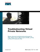
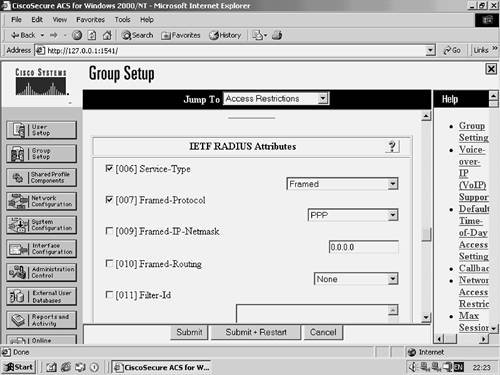
Figure 4-31 shows the erroneous L2TP tunnel definition configuration within Group Setup on the CiscoSecure ACS. Note that the group corresponds to user mjlnet.com.

As you can see, the VPDN tunnel ID is configured as 12. The tunnel ID is modified to reflect the hostname of the LAC (Calcity_LAC).
Figure 4-32 shows the new configuration of the VPDN tunnel ID within Group Setup on the CiscoSecure ACS.

Once the VPDN tunnel ID has been corrected, the remote access client reconnects to the LAC, and L2TP tunnel establishment is successful.
To verify successful tunnel establishment, use the show vpdn tunnel all, as demonstrated in Example 4-119.
Example 4-119. Verifying Successful L2TP Tunnel Establishment
CalCity_LAC#show vpdn tunnel all L2TP Tunnel Information Total tunnels 1 sessions 1 Tunnel id 16148 is up, remote id is 63863, 1 active sessions Tunnel state is established, time since change 00:00:58 Remote tunnel name is Skydance_LNS Internet Address 172.16.5.5, port 1701 Local tunnel name is CalCity_LAC Internet Address 172.16.1.1, port 1701 20 packets sent, 34 received 1574 bytes sent, 1776 received Control Ns 4, Nr 2 Local RWS 800 (default), Remote RWS 800 (max) Retransmission time 1, max 1 seconds Unsent queuesize 0, max 0 Resend queuesize 0, max 2 Total resends 0, ZLB ACKs sent 0 Current nosession queue check 0 of 5 Retransmit time distribution: 0 0 0 0 0 0 0 0 0 Sessions disconnected due to lack of resources 0 %No active L2F tunnels %No active PPTP tunnels %No active PPPoE tunnels CalCity_LAC# |
Highlighted line 1 shows that one L2TP tunnel and one session have been successfully established. Highlighted lines 2 and 3 show the remote tunnel name (Skydance_LNS), together with the LNS's IP address and UDP port over which the L2TP tunnel has been established. Highlighted lines 4 and 5 show the local tunnel name (CalCity_LAC), together with the LAC's IP address and UDP port over which the will to tunnel has been established. L2TP tunnel setup is successful, and the issue has been resolved.
Other common issues with tunnel definitions are user password misconfiguration, service-type (attribute 6) misconfiguration, and IP address assignment. When configuring tunnel definitions, ensure that the password of the user (domain) associated with the tunnel definition is cisco on the RADIUS server. This must be used because it is hard-coded on Cisco routers.
Additionally, the service-type (attribute 6) should be configured as outbound or dialout framed. This attribute can be found in group setup if you are using a CiscoSecure ACS.
If you are using a CiscoSecure ACS, ensure that No IP Assignment is specified in either the user or group setup (remember that IPCP will be negotiated with the LNS, and not the LAC).
Finally, it is also worth briefly examining an L2TP tunnel definition in Merit format using Cisco AVPs.
Example 4-120 shows an L2TP tunnel definition on a Merit RADIUS server.
Example 4-120. L2TP Tunnel Definition on a Merit RADIUS Server
mjlnet.com Password = "cisco" Service-Type = Outbound-User, cisco-avpair = "vpdn:tunnel-id=CalCity_LAC", cisco-avpair = "vpdn:tunnel-type=l2tp", cisco-avpair = "vpdn:ip-addresses=172.16.5.5", cisco-avpair = "vpdn:l2tp-tunnel-password=cisco" |
Highlighted line 1 shows the username (mjlnet.com). This is the domain name contained within the usernames of remote access clients (username@domain_name) connecting to the LAC. Also in highlighted line 1 is the hard-coded password for Cisco routers (cisco). The service type (Outbound-User) is shown in highlighted line 2.
Highlighted lines 3 to 6 show the tunnel ID (CalCity_LAC), the IP address of the LNS (172.16.5.5), and the shared tunnel password (cisco in this example).
Case Study 2: Remote AAA (RADIUS) Authentication Failure on the LNS
When supporting more than a handful of remote access clients, authentication using remote AAA is a much more viable option than local authentication on the LNS. Troubleshooting remote AAA authentication on the LNS does not need to be that much more difficult than troubleshooting local authentication.
The first command used when troubleshooting this issue is debug ppp negotiation. You can use this command to confirm that authentication is indeed causing PPP negotiation failure between the remote access client and the LNS.
Example 4-121 shows the output of the debug ppp negotiation command with authentication failure. Note that only the relevant portion of the output is shown.
Example 4-121. PPP Authentication Failure on the LNS
Skydance_LNS#debug ppp negotiation PPP protocol negotiation debugging is on Skydance_LNS# Feb 11 00:38:30.811 UTC: Vi1 PPP: Phase is AUTHENTICATING, by this end Feb 11 00:38:30.811 UTC: Vi1 CHAP: O CHALLENGE id 24 len 33 from "Skydance_LNS" Feb 11 00:38:30.811 UTC: Vi1 CHAP: I RESPONSE id 24 len 40 from "[email protected]" Feb 11 00:38:30.975 UTC: Vi1 CHAP: Unable to validate Response. Username [email protected]: Authentication failure Feb 11 00:38:30.975 UTC: Vi1 CHAP: O FAILURE id 24 len 14 msg is "RejectedJM" Feb 11 00:38:30.975 UTC: Vi1 PPP: Phase is TERMINATING Feb 11 00:38:30.979 UTC: Vi1 LCP: O TERMREQ [Open] id 1 len 4 Feb 11 00:38:30.991 UTC: Vi1 LCP: I TERMACK [TERMsent] id 1 len 4 Feb 11 00:38:30.991 UTC: Vi1 LCP: State is Closed Feb 11 00:38:30.991 UTC: Vi1 PPP: Phase is DOWN Skydance_LNS# |
The PPP authentication phase begins in highlighted line 1. In highlighted line 2, the LNS sends a CHAP challenge to the remote access client. Then in highlighted line 3, the remote access client ([email protected]) sends its response.
Highlighted line 4 is where things start to go downhill. The LNS reports that it is unable to validate the remote access client response. A CHAP failure message is then sent to the remote access client (highlighted line 5). The PPP phase changes to TERMINATING in highlighted line 6, and in highlighted line 7, the LNS sends an LCP Terminate-Request (TERMREQ) to the remote access client. The client responds with a Terminate-Ack (TERMACK) in highlighted line 8. The PPP phase changes state to DOWN in highlighted line 9, and the connection is terminated. It seems that the problem is an authentication failure.
Because RADIUS is being used, two more commands that can be used to clarify what is going on are debug aaa authentication and debug radius. When the remote access client reconnects, the debug aaa authentication command is used.
Example 4-122 shows the output of the debug aaa authentication command.
Example 4-122. debug aaa authentication Command Output
Skydance_LNS#debug aaa authentication AAA Authentication debugging is on Skydance_LNS# Feb 11 00:39:17.271 UTC: %LINK-3-UPDOWN: Interface Virtual-Access1, changed state to up Skydance_LNS# Feb 11 00:39:17.391 UTC: AAA: parse name=Virtual-Access1 idb type=21 tty=-1 Feb 11 00:39:17.391 UTC: AAA: name=Virtual-Access1 flags=0x11 type=5 shelf=0 slot=0 adapter=0 port=1 channel=0 Feb 11 00:39:17.391 UTC: AAA/MEMORY: create_user (0x62ED5038) user='[email protected]' ruser='NULL' ds0=0 port='Virtual-Access1' rem_addr='1111/7777' authen_type=CHAP service=PPP priv=1 initial_task_id='0' Feb 11 00:39:17.391 UTC: AAA/AUTHEN/START (1139933244): port='Virtual-Access1' list='' action=LOGIN service=PPP Feb 11 00:39:17.391 UTC: AAA/AUTHEN/START (1139933244): using "default" list Feb 11 00:39:17.391 UTC: AAA/AUTHEN/START (1139933244): Method=radius (radius) Feb 11 00:39:17.395 UTC: AAA/AUTHEN (1139933244): status = FAIL Feb 11 00:39:17.395 UTC: AAA/MEMORY: free_user (0x62ED5038) user='[email protected]' ruser='NULL' port='Virtual-Access1' rem_addr='1111/7777' authen_type=CHAP service=PPP priv=1 Feb 11 00:39:21.239 UTC: %LINK-3-UPDOWN: Interface Virtual-Access1, changed state to down Skydance_LNS# |
Virtual-access interface 1 changes state to up in highlighted line 1. The remote access client has connected to the LNS. In highlighted line 2, user [email protected] is created. Highlighted line 3 shows that login authentication for service ppp is taking place. Highlighted line 4 then shows that the default method list has been chosen, and that the authentication method is RADIUS (highlighted line 5). Unfortunately, as you can see in highlighted line 6, RADIUS authentication fails.
The debug radius command shows this process a little more clearly, as demonstrated in Example 4-123.
Example 4-123. debug radius Command Output
Skydance_LNS#debug radius Radius protocol debugging is on Skydance_LNS# Feb 11 00:39:41.315 UTC: %LINK-3-UPDOWN: Interface Virtual-Access1, changed state to up Feb 11 00:39:41.315 UTC: RADIUS: ustruct sharecount=1 Feb 11 00:39:41.315 UTC: RADIUS: Initial Transmit Virtual-Access1 id 39 10.20.10.5:1645, Access-Request, len 102 Feb 11 00:39:41.315 UTC: Attribute 4 6 0A020201 Feb 11 00:39:41.315 UTC: Attribute 5 6 00000001 Feb 11 00:39:41.315 UTC: Attribute 61 6 00000005 Feb 11 00:39:41.315 UTC: Attribute 1 21 6A6F6562 Feb 11 00:39:41.315 UTC: Attribute 30 6 37373737 Feb 11 00:39:41.319 UTC: Attribute 31 6 32323232 Feb 11 00:39:41.319 UTC: Attribute 3 19 21C686AF Feb 11 00:39:41.319 UTC: Attribute 6 6 00000002 Feb 11 00:39:41.319 UTC: Attribute 7 6 00000001 Feb 11 00:39:41.803 UTC: RADIUS: Received from id 39 10.20.10.5:1645, Access-Reject, len 32 Feb 11 00:39:41.803 UTC: Attribute 18 12 52656A65 Skydance_LNS# |
In highlighted line 1, the virtual-access interface 1 changes state to up. The remote access client is now connected to the LNS.
Highlighted line 2 shows the LNS transmitting an access-request message to the RADIUS server. This access-request message is used to authenticate the remote access client and contains a number of attributes, such as the remote access client's username and password.
Then in highlighted line 3, a response is received from the RADIUS server. This takes the form of an access-reject message. The access-reject message indicates that the information contained in the access-request message was invalid. Authentication has failed.
An authentication failure indicates that the username or the password is incorrectly configured on either the remote access client or the RADIUS server. In this case, the remote access client confirms that the username and password are correctly configured. Therefore, one or the other must be incorrectly configured on the RADIUS server.
The username is correct on the RADIUS server, so the only other possibility is that the password is incorrect. The password, therefore, must be corrected. A CiscoSecure ACS is being used in this case, and the password is corrected within the user setup.
Figure 4-33 shows the password configuration within the user setup.

The remote access client reconnects, and authentication succeeds. This is confirmed using the show caller user command, as demonstrated in Example 4-124.
Example 4-124. Verifying PPP Negotiation Success
Skydance_LNS#show caller user [email protected] User: [email protected], line Vi1, service PPP L2TP Connected for 00:06:44, Idle for 00:00:26 Timeouts: Limit Remaining Timer Type PPP: LCP Open, multilink Closed, CHAP (<- none), IPCP IP: Local 172.16.5.5, remote 10.1.1.1 VPDN: NAS CalCity_LAC, MID 2, MID Unknown HGW , NAS CLID 0, HGW CLID 0, tunnel open Counts: 116 packets input, 8192 bytes, 0 no buffer 0 input errors, 0 CRC, 0 frame, 0 overrun 176 packets output, 8698 bytes, 0 underruns 0 output errors, 0 collisions, 0 interface resets Skydance_LNS# |
In highlighted line 1, you can see that user [email protected] is connected to interface virtual-access 1 (vi1).
Highlighted line 2 shows that LCP is in an open state, that PPP multilink was not negotiated and is in a closed state, that the authentication protocol used is CHAP, and that IPCP was negotiated.
Highlighted line 3 shows the IP address configured on virtual-access interface 1 (172.16.5.5), together with the IP address assigned to the remote access client (10.1.1.1).
Finally, in highlighted line 4, the hostname of the LAC (CalCity_LAC) is shown. The issue has been resolved.
Case Study 3: Remote AAA (RADIUS) Authorization Failure on the LNS
When using remote AAA on the LNS, the RADIUS server not only authenticates but also authorizes remote access clients. If RADIUS attributes are not configured correctly, authorization will fail. If authorization fails, PPP negotiation with the remote access client will also fail.
To debug an authorization failure, the first command to use is the debug ppp negotiation command, as demonstrated in Example 4-125. Only the relevant portion of the output is shown.
Example 4-125. debug ppp negotiation Command Output
Skydance_LNS#debug ppp negotiation PPP protocol negotiation debugging is on Skydance_LNS# Feb 11 00:50:23.511 UTC: Vi1 PPP: Phase is AUTHENTICATING, by this end Feb 11 00:50:23.511 UTC: Vi1 CHAP: O CHALLENGE id 55 len 33 from "Skydance_LNS" Feb 11 00:50:23.511 UTC: Vi1 CHAP: I RESPONSE id 55 len 40 from "[email protected]" Feb 11 00:50:23.527 UTC: Vi1 CHAP: O FAILURE id 55 len 24 msg is "Authorization failed" Feb 11 00:50:23.527 UTC: Vi1 PPP: Phase is TERMINATING Feb 11 00:50:23.527 UTC: Vi1 LCP: O TERMREQ [Open] id 1 len 4 Feb 11 00:50:23.543 UTC: Vi1 LCP: I TERMACK [TERMsent] id 1 len 4 Feb 11 00:50:23.543 UTC: Vi1 LCP: State is Closed Feb 11 00:50:23.543 UTC: Vi1 PPP: Phase is DOWN Skydance_LNS# |
In highlighted line 1, the PPP phase changes to AUTHENTICATING, and authentication begins. The first thing that happens during the authentication phase is that the LNS sends a CHAP challenge to the remote access client (highlighted line 2). The remote access client replies with a CHAP response message (highlighted line 3). Note the username of the remote access client shown in the response message ([email protected]).
Then in highlighted line 4, the LNS sends a CHAP failure message to the remote access client. Note that the accompanying message indicates that authorization has failed.
Once authorization has failed, the PPP phase changes to TERMINATING (highlighted line 5), and the LNS sends a TERMREQ message to the remote access client (highlighted line 6).
In highlighted line 7, the remote access client responds with a TERMACK, and finally in highlighted line 8, the PPP phase changes to DOWN. Authorization has failed, and PPP negotiation between the remote access client and the LNS has been terminated.
To debug AAA authorization failures, the debug aaa authorization and debug radius commands are very useful. When the remote access client reconnects, the debug aaa authorization command is used.
Examples 4-126 to 4-127 show the output of the debug aaa authorization command.
Example 4-126. debug aaa authorization Command Output
Skydance_LNS#debug aaa authorization AAA Authorization debugging is on Skydance_LNS# Feb 11 00:51:25.475 UTC: %LINK-3-UPDOWN: Interface Virtual-Access1, changed state to up Feb 11 00:51:25.475 UTC: AAA: parse name=Virtual-Access1 idb type=21 tty=-1 Feb 11 00:51:25.475 UTC: AAA: name=Virtual-Access1 flags=0x11 type=5 shelf=0 slot=0 adapter=0 port=1 channel=0 Feb 11 00:51:25.475 UTC: AAA/MEMORY: create_user (0x628581B0) user='[email protected]' ruser='' port='Virtual-Access1' rem_addr='2222/7777' authen_type=CHAP service=PPP priv=1 Feb 11 00:51:25.867 UTC: Vi1 AAA/AUTHOR/LCP: Authorize LCP Feb 11 00:51:25.867 UTC: Vi1 AAA/AUTHOR/LCP (463461848): Port='Virtual-Access1' list='' service=NET Feb 11 00:51:25.867 UTC: AAA/AUTHOR/LCP: Vi1 (463461848) user='[email protected]' |
Virtual-access interface 1 changes state to up in highlighted line 1 (Example 4-126), indicating that the remote access client has connected to the LNS. In highlighted line 2, user [email protected] is created. Authorization then fails, as shown in Example 4-127.
Example 4-127. Authorization Fails
Feb 11 00:51:25.867 UTC: Vi1 AAA/AUTHOR/LCP (463461848): send AV service=ppp Feb 11 00:51:25.867 UTC: Vi1 AAA/AUTHOR/LCP (463461848): send AV protocol=lcp Feb 11 00:51:25.867 UTC: Vi1 AAA/AUTHOR/LCP (463461848): found list "default" Feb 11 00:51:25.867 UTC: Vi1 AAA/AUTHOR/LCP (463461848): Method=radius (radius) Feb 11 00:51:25.867 UTC: Vi1 AAA/AUTHOR (463461848): Post authorization status = FAIL Feb 11 00:51:25.867 UTC: Vi1 AAA/AUTHOR/LCP: Denied Feb 11 00:51:25.867 UTC: AAA/MEMORY: free_user (0x628581B0) user='[email protected]' ruser='' port='Virtual-Access1' rem_addr='2222/7777' authen_type=CHAP service=PPP priv=1 Skydance_LNS# |
Authorization is sought for service ppp and protocol lcp (highlighted lines 1 and 2, Example 4-127). The default method list is selected, and RADIUS authorization is chosen (highlighted lines 3 and 4). Authorization with the RADIUS server now begins.
The RADIUS server responds to the authorization request, and in highlighted line 5, the response is shown. Authorization has failed.
The debug radius command can be used to show the authorization process in greater detail. When the remote access client reconnects to the LNS, the debug radius command is used. Example 4-128 shows the output of the debug radius command when the remote access client reconnects.
Example 4-128. debug radius Command Output
Skydance_LNS#debug radius Radius protocol debugging is on Skydance_LNS# Feb 11 00:51:55.643 UTC: %LINK-3-UPDOWN: Interface Virtual-Access1, changed state to up Feb 11 00:51:55.643 UTC: RADIUS: ustruct sharecount=1 Feb 11 00:51:55.643 UTC: RADIUS: Initial Transmit Virtual-Access1 id 80 10.20.10.5:1645, Access-Request, len 102 Feb 11 00:51:55.643 UTC: Attribute 4 6 0A020201 Feb 11 00:51:55.643 UTC: Attribute 5 6 00000001 Feb 11 00:51:55.643 UTC: Attribute 61 6 00000005 Feb 11 00:51:55.647 UTC: Attribute 1 21 6A6F6562 Feb 11 00:51:55.647 UTC: Attribute 30 6 37373737 Feb 11 00:51:55.647 UTC: Attribute 31 6 32323232 Feb 11 00:51:55.647 UTC: Attribute 3 19 46F252F6 Feb 11 00:51:55.647 UTC: Attribute 6 6 00000002 Feb 11 00:51:55.647 UTC: Attribute 7 6 00000001 Skydance_LNS# Feb 11 00:51:55.659 UTC: RADIUS: Received from id 80 10.20.10.5:1645, Access-Accept, len 38 Feb 11 00:51:55.659 UTC: Attribute 6 6 00000001 Feb 11 00:51:55.659 UTC: Attribute 7 6 00000001 Feb 11 00:51:55.659 UTC: Attribute 8 6 FFFFFFFF Feb 11 00:51:55.659 UTC: RADIUS: no appropriate authorization type for user. Skydance_LNS# |
Highlighted line 1 shows virtual-access interface 1 changing state to up. The remote access client has connected.
Highlighted line 2 shows the LNS trying to authenticate and authorize the remote access client by sending an access-request message to the RADIUS server.
Highlighted line 3 shows that a response has been received from the RADIUS server. The response is an access-accept message.
The access-accept message seems to indicate all is well, but in highlighted line 4, the LNS reports no appropriate authorization type for user. This indicates that authorization has failed.
An investigation of the user and group setup on the CiscoSecure ACS reveals the problem.
Figure 4-34 shows the IETF RADIUS attributes configured within the user's group settings.

As you can see, the Service-Type attribute is configured as Framed, but the Framed-protocol is not checked. This is the problem. The Framed-protocol should be checked and specified as PPP, as shown in Figure 4-35.
Once the group settings (IETF RADIUS attributes) have been corrected, the remote access client reconnects. PPP negotiation between the remote access client is now successful, which you can confirm using the show caller user command, as demonstrated in Example 4-129.
Example 4-129. Verifying PPP Negotiation
Skydance_LNS#show caller user [email protected] User: [email protected], line Vi1, service PPP L2TP Connected for 00:01:02, Idle for 00:00:45 Timeouts: Limit Remaining Timer Type - - - PPP: LCP Open, multilink Closed, CHAP (<- none), IPCP IP: Local 172.16.5.5, remote 10.1.1.1 VPDN: NAS CalCity_LAC, MID 3, MID Unknown HGW , NAS CLID 0, HGW CLID 0, tunnel open Counts: 40 packets input, 3864 bytes, 0 no buffer 0 input errors, 0 CRC, 0 frame, 0 overrun 34 packets output, 1567 bytes, 0 underruns 0 output errors, 0 collisions, 0 interface resets Skydance_LNS# |
Highlighted line 1 shows that user [email protected] is connected to interface virtual-access 1 (vi1). In highlighted line 2, you can see that LCP is in an open state, PPP multilink was not negotiated and is in a closed state, the authentication protocol is CHAP, and IPCP was negotiated. Then in highlighted line 3, you can see the IP address configured on virtual-access interface 1 (172.16.5.5), together with the IP address assigned to the remote access client (10.1.1.1). Finally, in highlighted line 4, the hostname of the LAC (CalCity_LAC) is shown.
Case Study 4: AAA (RADIUS) Server Unreachable from the LNS
When using RADIUS servers, you must of course ensure that the server or servers (if more than one is configured) are reachable. To troubleshoot AAA server connectivity problems, the first command to use is the debug ppp negotiation command.
Examples 4-130 to 4-131 show the output of the debug ppp negotiation command when the RADIUS server is unreachable. Note that only the relevant portion of the output is shown.
Example 4-130. debug ppp negotiation Command Output
Skydance_LNS#debug ppp negotiation PPP protocol negotiation debugging is on Skydance_LNS# Feb 11 00:59:00.827 UTC: Vi1 PPP: Phase is AUTHENTICATING, by this end Feb 11 00:59:00.827 UTC: Vi1 CHAP: O CHALLENGE id 76 len 33 from "Skydance_LNS" Feb 11 00:59:00.827 UTC: Vi1 CHAP: I RESPONSE id 77 len 40 from "[email protected]" Feb 11 00:59:02.827 UTC: Vi1 LCP: TIMEout: State Open Feb 11 00:59:10.711 UTC: Vi1 CHAP: I RESPONSE id 77 len 40 from "[email protected]" Feb 11 00:59:10.711 UTC: Vi1 AUTH: Duplicate authentication request id=77 already in progress Feb 11 00:59:20.711 UTC: Vi1 CHAP: I RESPONSE id 77 len 40 from "[email protected]" Feb 11 00:59:20.711 UTC: Vi1 AUTH: Duplicate authentication request id=77 already in progress |
In highlighted line 1, the PPP phase changes to AUTHENTICATING. Highlighted line 2 shows the LNS sending a CHAP challenge to the remote access client, and in highlighted line 3, the response is received ([email protected]). This all looks good, and now either a success or failure message should be sent by the LNS to indicate whether or not authentication was successful.
But in highlighted line 4, another CHAP response message is received from the remote access client. Then in highlighted line 5, yet another response message is received. But no success or failure message is sent to the remote access client by the LNS.
In Example 4-131, the LNS is unable to validate the remote access client's CHAP response.
Example 4-131. LNS Is Unable to Validate the Remote Access Client's CHAP Response
Feb 11 00:59:20.831 UTC: Vi1 CHAP: Unable to validate Response. Username [email protected]: Authentication failure Feb 11 00:59:20.831 UTC: Vi1 CHAP: O FAILURE id 77 len 27 msg is "No response from server" Feb 11 00:59:20.831 UTC: Vi1 PPP: Phase is TERMINATING Feb 11 00:59:20.831 UTC: Vi1 LCP: O TERMREQ [Open] id 1 len 4 Feb 11 00:59:20.843 UTC: Vi1 LCP: I TERMACK [TERMsent] id 1 len 4 Feb 11 00:59:20.843 UTC: Vi1 LCP: State is Closed Feb 11 00:59:20.847 UTC: Vi1 PPP: Phase is DOWN Skydance_LNS# |
In highlighted line 1 (Example 4-131), the LNS reports that it is unable to validate the remote access client's response message, and authentication has failed. This is communicated to the remote access client when the LNS sends it a failure message in highlighted line 2. Notice the text sent with the failure message: No response from server. This is a pretty hefty hint as to the problem.
In highlighted line 3, the PPP phase changes to TERMINATING, and in highlighted line 4, the LNS sends a Terminate-Request (TERMREQ) message to the remote access client. Immediately thereafter, in highlighted line 5, the remote access client replies with a Terminate-Ack (TERMACK) message. Finally, in highlighted line 6, the PPP phase changes to DOWN. The remote access client has disconnected.
You can also use the debug aaa authentication and debug radius commands to troubleshoot this issue.
Example 4-132 shows the output of the debug aaa authentication command.
Example 4-132. debug aaa authentication Command Output
Skydance_LNS#debug aaa authentication AAA Authentication debugging is on Skydance_LNS# Feb 11 00:56:05.539 UTC: %LINK-3-UPDOWN: Interface Virtual-Access1, changed state to up Feb 11 00:56:05.663 UTC: AAA: parse name=Virtual-Access1 idb type=21 tty=-1 Feb 11 00:56:05.663 UTC: AAA: name=Virtual-Access1 flags=0x11 type=5 shelf=0 slot=0 |
Interface virtual-access 1 changes state to up in highlighted line 1, and the remote access client is connected to the LNS. User [email protected] is created in highlighted line 2. The authentication type is listed as CHAP, and the service as PPP. In highlighted line 3, the action is shown as LOGIN, and again the service is shown as PPP. The default method list is selected for authentication in highlighted line 4, and the method is RADIUS (highlighted line 5).
In highlighted line 6, an error is returned. This is not good. Notice that the status is neither pass nor fail. The error actually tells you that communication was not successfully established with the RADIUS server.
Then in highlighted line 7, the LNS indicates that there are no other authentication methods left to try, and that authentication has failed (highlighted line 8).
This can be seen more clearly using the debug radius command, as demonstrated in Example 4-133.
Example 4-133. debug radius Command Output
Skydance_LNS#debug radius Radius protocol debugging is on Skydance_LNS# Feb 11 01:01:23.763 UTC: %LINK-3-UPDOWN: Interface Virtual-Access1, changed state to up Skydance_LNS# Feb 11 01:01:23.763 UTC: RADIUS: ustruct sharecount=1 Feb 11 01:01:23.763 UTC: RADIUS: Initial Transmit Virtual-Access1 id 91 10.20.10.5:1645, Access-Request, len 102 Feb 11 01:01:23.763 UTC: Attribute 4 6 0A020201 Feb 11 01:01:23.763 UTC: Attribute 5 6 00000001 Feb 11 01:01:23.763 UTC: Attribute 61 6 00000005 Feb 11 01:01:23.763 UTC: Attribute 1 21 6A6F6562 Feb 11 01:01:23.767 UTC: Attribute 30 6 37373737 Feb 11 01:01:23.767 UTC: Attribute 31 6 32323232 Feb 11 01:01:23.767 UTC: Attribute 3 19 50A99C0E Feb 11 01:01:23.767 UTC: Attribute 6 6 00000002 Feb 11 01:01:23.767 UTC: Attribute 7 6 00000001 Skydance_LNS# Feb 11 01:01:28.767 UTC: RADIUS: Retransmit id 91 Skydance_LNS# Feb 11 01:01:33.767 UTC: RADIUS: Retransmit id 91 Skydance_LNS# Feb 11 01:01:38.767 UTC: RADIUS: Retransmit id 91 Skydance_LNS# Feb 11 01:01:43.767 UTC: RADIUS: Marking server 10.20.10.5:1645,1646 dead Feb 11 01:01:43.767 UTC: RADIUS: Tried all servers. Feb 11 01:01:43.767 UTC: RADIUS: No valid server found. Trying any viable server Feb 11 01:01:43.767 UTC: RADIUS: Tried all servers. Feb 11 01:01:43.767 UTC: RADIUS: No response for id 91 Feb 11 01:01:43.767 UTC: RADIUS: No response from server Skydance_LNS# |
Highlighted line 1 shows virtual-access interface 1 changing state to up. In highlighted line 2, an access-request message is sent to the RADIUS server. This access-request message includes a number of attributes, such as the remote access client's username and password.
The message is retransmitted by the LNS in highlighted lines 3, 4, and 5. No response is received from the RADIUS server, and in highlighted line 6, the LNS indicates that it considers the RADIUS server (10.20.10.5) to be dead. In highlighted line 7, the LNS indicates that no valid server has been found, and that it will try any valid server. Then finally in highlighted line 8, the LNS reports that there has been no response.
The lack of response from the RADIUS server could be due to a number of reasons. Some common reasons are a lack of IP connectivity between the LNS and the RADIUS server, misconfiguration of the RADIUS server's IP address on the LNS (or vice-versa), or a mismatched RADIUS server key. You should test IP connectivity using a ping.
Example 4-134 shows the output of the ping command when pinging the RADIUS server.
Example 4-134. Testing IP Connectivity to the RADIUS Server
Skydance_LNS#ping 10.20.10.5 Type escape sequence to abort. Sending 5, 100-byte ICMP Echos to 10.20.10.5, timeout is 2 seconds: U.U.U Success rate is 0 percent (0/5) Skydance_LNS# |
As you can see, there is no IP connectivity to the RADIUS server from the LNS.
In this case, removing an access list on an intermediate router (not shown) restores IP connectivity to the RADIUS server. The remote access client reconnects to the LNS, and authentication succeeds, as verified by using the show caller user command in Example 4-135.
Example 4-135. Verifying PPP Negotiation
Skydance_LNS#show caller user [email protected] User: [email protected], line Vi1, service PPP L2TP Connected for 00:01:03, Idle for 00:00:45 Timeouts: Limit Remaining Timer Type - - - PPP: LCP Open, multilink Closed, CHAP (<- none), IPCP IP: Local 172.16.5.5, remote 10.1.1.1 VPDN: NAS CalCity_LAC, MID 4, MID Unknown HGW , NAS CLID 0, HGW CLID 0, tunnel open Counts: 40 packets input, 3864 bytes, 0 no buffer 0 input errors, 0 CRC, 0 frame, 0 overrun 30 packets output, 1339 bytes, 0 underruns 0 output errors, 0 collisions, 0 interface resets Skydance_LNS# |
Highlighted line 1 shows that user [email protected] is connected to interface virtual-access 1 (vi1).
In highlighted line 2, you can see that LCP is in an open state, PPP multilink is in a closed state, the authentication protocol is CHAP, and IPCP was negotiated.
Highlighted line 3 shows the IP address configured on virtual-access interface 1 (172.16.5.5), together with the IP address assigned to the remote access client (10.1.1.1). Then in highlighted line 4, the hostname of the LAC (CalCity_LAC) is shown. The remote access client has successfully connected to the LNS, and the issue is resolved.
Case Study 5: Voluntary Tunnel Mode Connectivity from a Windows 2000 Workstation Fails
In voluntary tunnel mode, two of the most popular client/LACs are Windows 2000 and Windows XP. However, the configuration of voluntary tunnel mode connectivity from these clients is not quite as simple as that for PPTP.
In this scenario, a Cisco router has been configured as an LNS, and a Windows 2000 client/LAC is attempting to connect to it. When the Windows 2000 client/LAC attempts to connect to the LNS, the result is the error message shown in Figure 4-36.
The Error Message in Figure 4-36 reveals that the Windows 2000 client/LAC does not have a certificate. You may be wondering what a certificate has to do with an L2TP tunnel. The certificate is needed because, by default, Windows 2000 is configured to secure L2TP tunnels with IPSec.
Figure 4-37 illustrates a L2TP tunnel secured with IPSec from the Windows 2000 client/LAC to the LNS.
Figure 4-37. L2TPv2 over IPSec Between a Windows 2000 Client/LAC and the LNS

There are two choices, therefore, when configuring a voluntary tunnel between a Windows 2000/XP client/LAC and an LNS: either IPSec must be disabled on the Windows 2000/XP client/LAC (consider the security implications before you do this), or the L2TP tunnel must be secured with IPSec using certificates or a preshared key.
L2TP Without IPSec
To disable IPSec on the Windows 2000/LAC, you must modify the Registry.
To disable IPSec protection for the L2TP tunnel, complete the following steps:
Step 1. | Run regedt32.exe. |
Step 2. | Open the following key in the Registry: HKEY_LOCAL_MACHINESystemCurrentControlSetServicesRasmanParameters |
Step 3. | Add the following value: Value Name: “ProhibitIpSec” Data Type: REG_DWORD Value:1 |
Step 4. | Reboot the Windows 2000/XP client/LAC. |
Always be very careful when modifying the Windows Registry because a mistake can, in extreme cases, make your machine unbootable.
Figure 4-38 shows the Registry on the Windows 2000/LAC being modified to disable IPSec protection for L2TP tunnels.

Once IPSec has been disabled for L2TP on the Windows 2000 client/LAC, it reconnects to the LNS successfully.
Use the show vpdn tunnel all command to verify this is a successful connection, as demonstrated in Example 4-136.
Example 4-136. Verifying L2TP Tunnel Setup
Skydance_LNS#show vpdn tunnel all L2TP Tunnel Information Total tunnels 1 sessions 1 Tunnel id 2597 is up, remote id is 9, 1 active sessions Tunnel state is established, time since change 00:00:57 Remote tunnel name is mark3-note Internet Address 10.10.10.54, port 1701 Local tunnel name is Skydance_LNS Internet Address 172.16.5.5, port 1701 46 packets sent, 71 received 2632 bytes sent, 7425 received Control Ns 2, Nr 4 Local RWS 10000 (default), Remote RWS 8 Tunnel PMTU checking disabled Retransmission time 1, max 1 seconds Unsent queuesize 0, max 0 Resend queuesize 0, max 1 Total resends 0, ZLB ACKs sent 2 Current nosession queue check 0 of 5 Retransmit time distribution: 0 2 0 0 0 0 0 0 0 Sessions disconnected due to lack of resources 0 %No active L2F tunnels %No active PPTP tunnels %No active PPPoE tunnels Skydance_LNS# |
Highlighted line 1 reveals that one tunnel and one session have been established.
In highlighted lines 2 and 3, the computer name of the remote access client/LAC (mark3-note) is shown, together with its IP address and UDP port over which the tunnel is established.
In highlighted lines 4 and 5, the local hostname (Skydance_LNS), IP address, and UDP port for the tunnel are shown.
L2TP tunnel connectivity between the Windows 2000 client/LAC and the LNS has been successfully established.
L2TP over IPSec with Preshared Keys
The other option to ensure that L2TP tunnel establishment is successful is to configure L2TP over IPSec on both the Windows 2000 client/LAC and the LNS.
In the following example, the Windows 2000 client/LAC and the LNS are configured for L2TP over IPSec using preshared keys.
NOTE
To configure Windows 2000 client/LACs for preshared key authentication, see Knowledge Base article 240262 on the Microsoft web site (www.microsoft.com).
For Windows XP client/LACs, see Knowledge Base article 281555.
Configure the Cisco LNS according to the instructions contained in the section entitled “Configuring IPSec Protection for L2TP in Voluntary Tunnel Mode with Pre-Shared Keys” at the beginning of this chapter.
Once IPSec has been configured, the Windows 2000 client/LAC successfully connects to the LNS. Verify connectivity using the show vpdn tunnel command, as demonstrated in Example 4-137.
Example 4-137. Verifying L2TP Tunnel Establishment
Skydance_LNS#show vpdn tunnel all L2TP Tunnel Information Total tunnels 1 sessions 1 Tunnel id 52577 is up, remote id is 3, 1 active sessions Tunnel state is established, time since change 00:00:14 Remote tunnel name is mark3-note Internet Address 10.10.10.54, port 1701 Local tunnel name is Skydance_LNS Internet Address 172.16.5.5, port 1701 21 packets sent, 54 received 1067 bytes sent, 5348 received Control Ns 2, Nr 4 Local RWS 10000 (default), Remote RWS 8 Tunnel PMTU checking disabled Retransmission time 1, max 1 seconds Unsent queuesize 0, max 0 Resend queuesize 0, max 1 Total resends 0, ZLB ACKs sent 2 Current nosession queue check 0 of 5 Retransmit time distribution: 0 2 0 0 0 0 0 0 0 Sessions disconnected due to lack of resources 0 %No active L2F tunnels %No active PPTP tunnels %No active PPPoE tunnels Skydance_LNS# |
Highlighted line 1 shows that one tunnel and one session have been established with the Windows 2000 client/LAC. Highlighted lines 2 and 3 show the remote tunnel name (computer name of the Windows 2000 client/LAC), together with its IP address and UDP port on which the connection has been established. In highlighted lines 4 and 5, the local tunnel name, IP address, and UDP port over which the tunnel is established are shown.
You can verify the IPSec tunnel between the remote access client/LAC and the LNS using the show crypto engine connections active and show crypto ipsec sa commands.
Example 4-138 shows the output of the show crypto engine connections active command.
Example 4-138. Verifying IPSec
Skydance_LNS#show crypto engine connections active ID Interface IP-Address State Algorithm Encrypt Decrypt 1 Ethernet1/0 172.16.5.5 set HMAC_SHA+DES_56_CB 0 0 2000 Ethernet1/0 172.16.5.5 set HMAC_SHA+DES_56_CB 0 84 2001 Ethernet1/0 172.16.5.5 set HMAC_SHA+DES_56_CB 47 0 Skydance_LNS# |
Highlighted line 1 shows the security association for ISAKMP. Note the hashing and encryption algorithms (SHA-1 and DES, respectively).
The IPSec security associations (inbound/outbound) are shown in highlighted lines 2 and 3. Again, the hashing and encryption algorithms are SHA-1 and DES.
You can obtain more detailed information about the IPSec security associations by using the show crypto ipsec sa command, as demonstrated in Example 4-139.
Example 4-139. Verifying IPSec Security Associations
Skydance_LNS#show crypto ipsec sa interface: Ethernet1/0 Crypto map tag: l2tpcryptomap, local addr. 172.16.5.5 local ident (addr/mask/prot/port): (172.16.5.5/255.255.255.255/0/0) remote ident (addr/mask/prot/port): (10.10.10.54/255.255.255.255/0/0) current_peer: 10.10.10.54 PERMIT, flags={transport_parent,} #pkts encaps: 0, #pkts encrypt: 0, #pkts digest 0 #pkts decaps: 0, #pkts decrypt: 0, #pkts verify 0 #pkts compressed: 0, #pkts decompressed: 0 #pkts not compressed: 0, #pkts compr. failed: 0, #pkts decompress failed: 0 #send errors 0, #recv errors 0 local crypto endpt.: 172.16.5.5, remote crypto endpt.: 10.10.10.54 path mtu 1500, media mtu 1500 current outbound spi: 0 inbound esp sas: inbound ah sas: inbound pcp sas: outbound esp sas: outbound ah sas: outbound pcp sas: local ident (addr/mask/prot/port): (172.16.5.5/255.255.255.255/17/0) remote ident (addr/mask/prot/port): (10.10.10.54/255.255.255.255/17/1701) current_peer: 10.10.10.54 PERMIT, flags={origin_is_acl,reassembly_needed,transport_parent,parent_is_transport |
Example 4-139 shows a huge amount of information. The name of the crypto map applied to the L2TP tunnel and the local IP address are shown in highlighted line 1. Highlighted lines 2 and 3 show the local and remote identities (IP addresses).
Then starting from highlighted lines 4 and 5, information concerning inbound and outbound ESP security associations is shown. This information includes the Security Parameter Index (SPI), transform set, and IPSec mode.
L2TP over IPSec tunnel connectivity has been successfully established between the Windows 2000 client/LAC and the LNS. The issue is resolved.
Note that more information about the configuration and troubleshooting of IPSec can be found in Chapter 8.