
Communication for Engineers
Abstract
This chapter examines the different means of communication available to engineers, from reports to drawings, and offers guidelines on how to optimise clarity in communication as well as how to follow correct convention in drawing and solid imaging. It covers in some detail typical errors in layout, dimensioning and parts list generation.
5.1 Communication Overview
“I am an engineer, not a communicator.” To the contrary—to be an engineer is to be a communicator. To be a design engineer is to be an exceptional communicator. Clear communication leads to effective solutions. Design engineers solve problems in situations where the solution very often lies in collaborating with other experts, personnel, designers, analysts, and marketers. Communication with those professionals is absolutely necessary.
It is important that design engineers recognize that they must communicate their ideas and developments to other parties. This can be done in several ways, depending on the kind of information that needs to be imparted. Information relating to manufacturing may usually be disseminated through the use of technical drawings and models. This kind of information is delivered toward the end of the design process. Prior to that point, there is an enormous requirement for precise and clear communication to other interested parties. This communication may be verbal, visual, written, or physical, depending on the information that needs to be imparted.
Designers may also need to liaise with a variety of interested parties, such as clients, manufacturers, suppliers, lawyers, patent agents, marketing specialists, distribution specialists, and packaging providers. Each of these individuals and groups will require information in a particular format and delivered in a particular style so that they can fulfill their work function. For instance, marketing specialists will require a description of the product’s benefits. Packaging people will themselves liaise with distribution specialists but will require information relating to the envelope of the product and the necessity for protection during shipping.
Whatever the information that needs to be imparted, several methods can be used to communicate it, depending on the audience. Generally design engineers need to be serious about the methods and accuracy of their communication techniques. To become an adept communicator, it is inevitable that basic tools of communication need to be assembled and used. These tools could include:
• Dictionary
• Thesaurus
• Reference books on grammar and writing styles
• Standard presentation techniques
• Computers with appropriate software
Depending on the audience, there are several methods of communication that, in one form or another, engineers should master. Some of these methods are discussed in the following sections.
5.2 Written Communication
5.2.1 Accuracy
As a matter of course, people often treat what they read as the final word. There is a great responsibility, therefore, for an author to write and publish data that is not only accurate but is backed up by appropriate analysis or information sources. In a technical report, the author should never offer opinions but should offer sound reasoning based on facts and other hard data. Furthermore, it is important that the author names the source, which has the additional advantage of avoiding plagiarism.
5.2.2 Presentation
Written communication in an official document needs to look official. Presentation is paramount in this case. A tatty, unstructured, unbound, unprofessionally presented document to get a quote for a project will give a poor impression to a client. On the other hand, a well-presented, bound, clear, concise, professionally presented written document would immediately create a good impression. This professional presentation indicates that the presenter cares for his work and would probably treat the project in the same meticulous way. Presentation can make or break a project, since it is a clear indicator of the presenter’s level of professionalism. It is useful here to remember the adage “There is only one opportunity to create a first impression.”
5.2.3 Research
During the first stages of a project, research needs to be done. That research generally takes two forms:
1. Information that allows an understanding of the relevant issues, facts, problems, and possible solutions
2. Information that will be presented to the audience
Often these two information elements overlap and vary greatly from project to project. The first type of information allows the designer to engage with the project and formulate a solution. The second type will probably overlap with the first type but might need to be greatly simplified so as not to confuse the audience with too many facts.
It is very easy for a researcher, or indeed a designer, to become so involved with and enthusiastic about the project that he imparts every detail to the audience. The reaction of the audience is likely to be that of boredom and eventual disinterest at the overwhelming level of tedious information.
It is important to realize, however, that research is an absolute necessity from the design point of view as well as to enable the designer to correctly respond to the audience. For instance, it would not be appropriate to impart technical information such as stresses, vibrations, and materials to an accountant. The information would serve no purpose and probably would not be understood because the discipline of the accountant is not tuned to understanding such technical information. In relating a project to said accountant, you must present the information in terms of costs, timescales, and budgets.
This example shows that information imparted to an audience needs to be presented in a particular way. The required research enables the designer to understand the audience and gives them the opportunity to tune the presentation material to attain the best reception from the audience.
5.2.4 Guidelines for effective writing
Effective writing really means planning ahead. A writing project needs a beginning, a middle portion, and an end. Planning is therefore required to understand what information needs to be put into each section. When you’re first beginning a project, this might seem a daunting task, but with appropriate research, appropriate design application, and effective planning, the task should become straightforward.
5.2.5 Planning
Planning is an essential component of writing effectively. Just as the designer may see the end result in her mind’s eye, so should the writer. The writer should see the shape of his narrative and be able to break it down into individual elements. In terms of a design report, the process should start with a brief, which can then be broken down and explored in smaller elements. The middle portion of the report should be split into smaller elements, each of which explores a single idea. The end of the report is a summary of these ideas leading to a conclusion or recommendation.
The preparation of an outline of the proposed work is highly desirable. This exercise helps the writer think through the composition and improve its internal order before actually commencing writing. In preparing an outline, an orderly framework is created with additional benefits of productivity and efficiency.
During the course of a long report the titles may change as the script develops. This may be due to recognition of a more efficient way out. Often the change in the script layout is due to changes in the design or new revelations brought about through ongoing research. An orderly framework allows the writer to easily change the format of the report.
5.2.6 Report structure
Writing the prose is always done in sentences that are elemental components of paragraphs. Typically, readers find it daunting to be faced with a page of pure, unbroken text. The text is therefore broken up into smaller units, called paragraphs. A paragraph is really the unit of composition and is grouped together in chapters, sections, and subsections, perhaps with appropriate headings or titles. If the end goal was given to the reader in one huge portion, he would become confused and disinterested. The chapter, subsection, and paragraph approach to structure leads the reader toward the end goal in a building-block approach, building on the story as the paragraphs progress. This leads to an interesting read for the audience, who should want to know more and more, rather like reading a good novel.
5.2.7 Crafting an interesting narrative
If the script is not interesting, the audience will not read it. The writing has to be tuned to the audience in order to make it interesting. An interesting read to a chief designer may prove to be completely boring to the company accountant. This point has been made previously, but it is so important to aim the writing toward the intended audience.
The narrative requires structure so that the reader is almost “led by the hand” through the report. Each chapter needs a start, beginning, and an end, which is exactly what people like to see. Chapters written in this format are effectively short stories.
It is always discouraging for a reader to be faced with lots of descriptive text. The authors should consider inserting pictures, diagrams, tables, and the like to improve readers’ understanding.
5.2.8 Graphics
“A picture is worth a thousand words.” This adage is very old but nevertheless is still very true. It is said that 80% of human learning occurs through visual input. Newspapers use pictures on their front pages to entice readers. In terms of report writing, this revelation indicates that pictures, diagrams, charts, graphs, and other visual representations can reduce the number of words in the report and grab the reader’s attention.
To emphasize this point, try describing a wheelbarrow to someone who has never seen one. Write your description as a letter or perhaps as an e-mail. The exercise will probably take at least two sides of A4 paper. Isn’t it easier to just sketch a drawing of the wheelbarrow?
Using graphical aids, we can reduce the number of words in a report, keeping the reader interested and better informed and improving understanding of the project.
There are several rules for inserting graphics into text, some of which are indicated here:
• Give each graphical element a number, such as figure number, table number, graph number, or plate number.
• Always refer to the graphics element from the main body of the text.
• Annotate sketches for improved clarity.
• If the report is to be photocopied, present graphics in black-and-white to ensure a sharper reproduction.
5.2.9 Brevity and clarity
The secret of good writing is often to strip every sentence to its minimal components. Short sentences are generally preferred over long sentences; short words are usually better than long words. A few examples follow:
Near is preferred over in close proximity
Scarce is preferred over in short supply
Now is preferred over at this point in time
Used car is preferred over previously owned vehicle
Library is preferred over communications resource center
Garbage collector is preferred over sanitation engineer
During an interview on a radio news bulletin, a subject specialist was heard to say, “It has a subnormal moisture content.” What he really meant was, “It’s dry”! The main rule here is “Keep it simple.”
Technical writing requires a certain professional standard whereby words such as okay, tremendous, terrific are not really suitable. They are not descriptive and merely convey opinions. Other faddish words and expressions such as prioritize, finalize, and the bottom line may also be viewed as unprofessional in a technical report.
5.2.10 Adapting the writing style to the intended audience
This element has been alluded to, but it is very important to understand how the audience will receive and understand your writing. The author must consider the audience’s educational background, socioeconomic level, age, and interests. For instance, writing intended for technical journals may contain scientific language, formulae, chemical symbols, and analysis. The target audience for this kind of publication would normally be educated to a level where the message could be easily understood. Articles or reports destined for a general audience require a much different style that uses plain language and simple illustrations. Personal and practical implications may also be stressed in such a report.
In presenting engineering subjects to young teenagers, the presenter must consider their educational level. In that age group, reading ability in technical areas could be expected to be almost nil, and to keep the interest of a normally “short attention span” audience, the presentation would need to be almost all graphical. Employing such tactics in the presentation is likely to keep the audience interested.
5.2.11 Things to avoid
In writing for any audience, try to avoid the following:
• Long words
• Jargon
• Abbreviations
• Euphemisms
• Calculations in the main body of text (put them in the appendix)
• Poor grammar
• Poor spelling
5.2.12 Rewriting and proofreading
In working on a project, one of the most difficult parts is starting with a blank piece of paper. In writing, it is creating the first draft—essentially creating something out of nothing. In the first draft, the author synthesizes the research, the requirements, and the perceptive needs of the audience into a readable piece of writing.
Once the first draft is completed, the next phase is rewriting. Rewriting is the molding of the first draft in an effort strives to make the piece readable and meaningful and to accurately reflect the work and thoughts developed during the project. When the rewrite is finished, the meaning should shine through, enabling the reader to absorb the essence from a seemingly effortless piece of writing.
Rewriting may take several revisions and should be proofread before publication. Rewriting may also be termed revising and editing. The writer must realize that a first draft will contain factual errors, spelling mistakes, and grammatical mistakes and should never be published without rewriting it at least once. Proofreading is usually the final step in preparing a document and is often applied to journal papers, books, and other published works.
5.2.13 Guidelines for revising, editing, and proofreading
The revision of the first draft should be done in a structured way. Guidelines are as follows:
• Structure and content:
• Ensure that the structure (report, proposal, etc.) is what the audience expects.
• Ensure that the data is complete.
• Are any omissions justified?
• Ensure that information gleaned from external sources is fully referenced. Information from open sources may be simply referenced by web site and access date.
• Check that section headings match the contents page.
• Check the logic and flow:
• Is the logic based on the reader’s knowledge base or the author’s?
• Ensure that each passage follows a logical theme from the previous passage.
• Edit line by line:
• Perform a line-by-line check for grammar and style.
• Check sentences for sense, clarity, and precision.
• Punctuation, spelling, grammar:
• Check for correct punctuation, spelling and grammar.
• Check for words left out.
• Check for consistency of headings.
• Read the document aloud to “hear” any remaining errors.
5.2.14 Logs and notebooks
Taking notes and minutes at meetings is normal practice because it creates a record of the details of the communication. It also allows names to be assigned to points to be actioned. Many engineers also maintain an informal record of their work by keeping a day-to-day diary, log, or notebook. Diary entries may be made from short conversations with colleagues, but more serious logs or notebooks should always be made when performing laboratory experiments or pursuing a particular part of a design, such as the selection of a power plant or completing some analysis. Carefully made and maintained records of this type provide a permanent and ready source of information for memoranda, letters, technical reports, and product complaints.
In one particular case, an extending handle for a golf bag was designed as two tubes, one sliding into the other. The safety factor was calculated at 4:1, which was deemed high for the duty. A subsequent product complaint was received, saying that the handle had bent, the inference being that it was not strong enough for the duty. Design analysis notes were quickly found and used to refute the complaint.
5.2.15 Memoranda, business letters, and e-mail
Before the e-mail age, memoranda and business letters were often used to communicate between departments within the same company and between businesses or to converse with clients. Memoranda were generally used to communicate between departments within the same company and fulfilled a similar function to that of e-mails today. Notably, today the use of memos has almost ceased with the advance and ease of use of e-mail systems.
Business letters, which used to be the norm, have also been overtaken by the ease of use of e-mail. Business letters are still frequently used, but for particular purposes. When it hits your desk, a business letter has a great deal of impact simply because today it is not the norm to receive paper communications. Business letters therefore tend to be used for specific reasons, such as delivering a contract, delivering an affidavit or legal document, or making the recipient notice the message by giving it paper impact.
In the modern business and design engineering environment, e-mail is one of the most common means of communication. E-mail is a message device that allows almost conversational communication but is clinical in that e-mails often do not follow the niceties of grammar rules, which make the message flow. E-mail’s main advantage is that it is instantaneous and global. A message sent from the United Kingdom can be received in the United States in seconds. Business letters cannot do this unless they are faxed, which incurs extra cost and low-quality reception. E-mails are so common that important messages can be overlooked. In such eventualities, the sender may choose to send a business letter, giving the message impact and garnering more attention.
5.3 Project Reports/Technical Reports
5.3.1 General approach to project reports
A technical report will follow a particular format that contains the necessary building blocks to create a complete information source. The report should be written in the third person, which means negating the use of personal pronouns such as I, we, and they. An example of the use of third person is: “The team decided that …” instead of “We decided that….” It is important to give the report a professional feel, and the use of the third person goes some way toward accomplishing this requirement.
The aim is to reduce written matter to a minimum. This can easily be accomplished by incorporating annotated sketches, diagrams, and 3-D models in preference to lengthy written descriptions. A credible report will also possess statements that have clear backing, either in calculation or by reference to an information source. This technique then avoids statements that are really opinions, such as, “It is heavier” or “It is cheaper.” It is necessary for the writer to qualify statements and suggest why it is heavier or cheaper and on what premise the author has based that statement.
Presentation can make or break a report. The adage “There is only one opportunity to create a first impression” should be paramount in the author’s mind. Sloppy, untidy reports may lead to readers’ rejection of the product idea, no matter how good the proposed design.
Every language has its preferred spelling and grammar, and it is important that the author create a document that is perceived to be grammatically correct and with correct spelling. Without this correct presentation, the report and its contents will be judged unprofessional.
It is necessary to adopt a reference method so that information elements can be stored in separate areas of the report. Items such as book titles, research articles, analysis, graphical information, bought-out parts, and company data are often placed in an appendix, bibliography, or reference sections and are referred to from the main body of text. One typical reference system is the Harvard Referencing System.
Several key elements constitute a formal report. These are listed as follows:
• Title
• Cover sheet (author’s name and perhaps contact details)
• Contents page
• Terms of reference
• Summary
• Introduction
• Main body of text
• Conclusions and recommendations
• References
• Bibliography
• Appendix
5.3.2 Title
A good descriptive title often sets the tone for the report and introduces the subject to the reader. A title is sometimes unavoidably lengthy in order to be comprehensively acceptable for an information retrieval system. An example of an effective project title could be: The Specification and Design of an Automatic Clamping Device for the Location and Clamping of a Family of 30 Components Within a Flexible Manufacturing Cell.
5.3.3 Cover sheet
As with a published book, this is the first page after the front leaf of the report and does not need to be numbered. The cover sheet should contain:
• Title
• Author’s name
• Contact details
• Project designation number
The cover sheet is normally signed and dated by the author.
5.3.4 Contents page
The contents page is the guide to the contents of the report and should list section and subsection headings, along with their page numbers. Depending on the size of the report, the contents “page” may extend to several pages. The inclusion of a contents page also means that the report should have numbered pages. This might seem obvious, but an incomplete contents page with no page numbers may be deemed unprofessionally presented. The contents page should therefore contain:
• A hierarchical numbering system for each section and subsection
• The titles of the main sections and subsections of the report
• Tables, figures, and plates detailing their number, full title, and page number
• Appendices with appropriate numbered sections and subsections
5.3.5 Terms of reference (generally the project brief)
Terms of reference are instigated by some commissioning body or person who is usually responsible for providing the brief. Any project requires a reason, but more important, who instigated or commissioned the project and subsequent report. Within a company the commissioners may be the board of directors. In government the commissioners may be a governmental subcommittee.
The brief is only one element of the terms of reference. Full terms of reference can also include measurable elements of the project and how those elements will be measured by the commissioners. Terms of reference may be fairly complex, since they give the commissioning body the means to control the outcome and, most often, the financial input. The creation of detailed terms of reference is therefore often critical, since they define:
• Vision, objectives, scope, and deliverables (i.e., what has to be achieved)
• Stakeholders, roles, and responsibilities (i.e., who will take part in the project)
• Resource, financial, and quality plans (i.e., how it will be achieved)
• Work breakdown structure and schedule (i.e., when it will be achieved)
• Success factors, risks and constraints
5.3.6 Summary (executive summary or abstract)
A summary should be brief and to the point. It will give the busy reader an insight into what the report contains without going into the detail of reading the whole report. The summary should be a précis of the report contents, culminating in a brief design specification and a list of product benefits. The summary should therefore contain:
• Objectives and purpose of the report
• Background information
• What the report has achieved
• The main findings
• Brief conclusions
• Specification (if appropriate)
The summary is important because it is used as the basis of decision making. After reading the summary, alongside the conclusions and recommendations sections, the technical manager or managing director should be able to make a decision as to the next stage in development.
5.3.7 Introduction
An effective introduction familiarizes the reader with the design challenge and provides background information. Essentially the introduction explains why the project is being undertaken. The introduction provides:
• Context: A cursory historical review
• Scope: An explanation of the challenge to be solved
• Purpose: An explanation of the basic need
• The reason for carrying out the work
• Procedure and methods
A typical introduction might be along the following lines:
There is a need to design a new form of rear-view mirror for the pedal cyclist. In the past, rear-view mirrors have taken the form of a small mirror mounted on a stem that protrudes sideways from the pedal bike frame or handlebars. When the rider dismounts and leans his bike against a wall, the mirror is often caught on the wall and bent out of position or out of shape.
It is required to design a mirror-mounting system that is not affected when the cycle is parked. The mirror-mounting system needs to be lightweight, robust, and easily viewed by the rider and must hold the mirror in a position for the rider see to the rear when cycling.
The reason for carrying out this work is to improve cyclist safety and to provide a solution to a perceived problem that is not catered for by the current cyclist mirror market.
Such an approach enables the reader to be gradually introduced to the design challenge. Should the reader want to glean more meaningful information, he or she can then read the report’s contents.
5.3.8 Main body of text
The main body of the report contains all the details of the method of thinking and design decisions. It is an explanation of the actions taken during the design process and the reason those actions were carried out.
This section should be explanatory but as concise as possible. Full use should be made of annotated sketches, 3-D models, charts and graphs, photographs, and indeed any other visual representations that reduce the amount of text. The aim here is to impart the information to the reader in an easy but accurate fashion. All visual items should be labeled in a numerical sequence preceded by labels: Figure 1, Figure 2, Figure 3, and so on for sketches, graphs, and diagrams; Plate 1, Plate 2, Plate 3 for photographs, and Table 1, Table 2, Table 3 for charts and tabular data.
Always qualify statements using data that has been derived by analysis or by research. A statement such as “It is cheaper” or “It is too heavy” is merely an opinion.
It is often necessary to include the results of analysis or research, but do not be tempted to include large swaths of analysis in the main report body. These results should be available to the reader in the appendix, suitably referenced in the main body of the report. Similarly, company brochures may be referred to from the main report body, but only selected pages should be available in a section of the appendix.
The technical report should always be written in the third person. Avoid the use of personal pronouns such as I, we, me, us, and they. A typical example here would be: “It was considered that a 28-tooth spur gear should be used because …” rather than “I decided that a 28-tooth spur gear should be used because.…”
Presentation can make or break a report. A scruffy presentation leaves the reader with an impression of sloppy work, whether or not the research and background work has been carefully executed. Consider the method of referencing, formatting, and eventual binding of the report. You have only one opportunity to create a first impression.
5.3.9 Conclusions and recommendations
Any piece of work that requires a written report is not complete without appropriate conclusions and recommendations. Often, conclusions and recommendations are the whole point of performing the work.
Conclusions and recommendations should be included at the end of the main report and should be short and to the point and should clearly indicate the major findings of the work.
Recommendations are the logical continuation of the work and outline what should be done in the future to continue the work that has just been completed.
5.3.10 Bibliography
Usually the bibliography takes the form of a list of books and papers and useful background reading. These are often related to a particular subject or a particular author and may form part of the references.
5.3.11 References
The reference section should contain a list of books and papers from which specific items have been used. Whenever any outside source has been consulted and subsequently included in the report, it must be included in the reference section. Any work referred to must include the title, author, location, and a reference number. This information is required so that readers can find the work themselves. For example, “It has been shown by Becker (1) that a rectangular orifice should tend to prevent bridging, whereas.…” In the reference section, this item would be referred to as follows:
1. Becker, P., “Bulk Flow of Powders,” Journal for Flour Graders, vol. 40, pp 981–994.
The intention of a reference is to direct the reader to a specific section of a book or article rather than for the book to be read completely.
5.3.12 Appendix
The appendix is often the final element of the report and may be large enough to warrant a separate volume. Information that appears in the appendix should be directly relevant to the design and should enhance the report by giving a clear understanding of the product being designed. Specific company brochure pages may be included rather than the whole brochure. The appendix may also give specific information to the purchasing department for components that have been specified as part of the design.
The appendix should contain:
• Information on standard bought-out parts
• Mathematical proofs
• Worked examples
• Tables
• Charts
• Information that can be used as evidence to substantiate the statements within the report body
Analysis should be presented here, with an appropriate reference number so that it can be referred to from the main body. The report must list the meaning of the symbols used in any formulas the report includes. It is usually necessary to quote the source of your equations, but it is not necessary to prove the formulae unless several equations have been combined.
5.3.13 Project layout
The same attributes you would expect to see in a published book should also be seen in a professional report. The layout should be neat, tidy, and formal. It should be easy to read in a structured manner, following a logical progression. A large part of the project layout aspect of the report is visual. The professional nature of a report is primarily visually conveyed (what people see) and secondarily by what people read. The visual and nonvisual layout of the report may be achieved with subtleties discussed here.
5.3.13.1 Logical progression
No matter what the subject, the report should convey a story and should unfold that story in a logical, step-by-step progression. In a design report, the beginning should consider a brief with the initial requirements and convey elements of research on which design decisions have been based. This first section should conclude in the concept design. The detail design section should then tell the story of components and materials selected, with reasons, and conclude with the final product specification.
During the process of conveying this information, the logical progression should take the reader from one aspect to the next logical step so that there is no reader confusion as to the route by which the design has arrived at a particular point.
5.3.13.2 General layout guidelines
5.3.13.2.1 Single page of text
In a formal report, it is normal convention use A4 paper and to place any text and graphics on the right margin of an open document. This leaves the left margin for the reader to make notes. See Figure 5.1. This style is very different to that of a published book, where the reader is not expected to make notes.
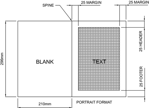
Figure 5.1Portrait Viewing Position for a Formal Report Using A4-Sized Paper [1]
5.3.13.2.2 Viewing position
When bound, the report should be opened so that the spine is vertical, which allows the reader to view the text in portrait format, that is, from the top of the right-hand page to the bottom. See Figure 5.1. Should wider pictures and diagrams be required to run in landscape format, it is usual to hold the spine horizontally and view the graphic from the bottom leaf of the reportSee Figure 5.2.
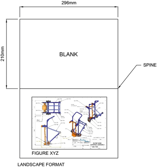
Figure 5.2Landscape Viewing Position for a Formal Report Using A4-Sized Paper [1]
5.3.13.2.3 Margins
A margin is the area between the main content of the page to the page edges, as shown in Figure 5.1. It helps to define where a line of text begins and ends. The margins’ purpose is to hold the text in a particular area on the page, subtly telling the reader that there is no text that has overspilled the page.
There are several formats for margins, depending on the document. A letter may have very wide margins in contrast to a technical report, which may have narrow margins. It must also be remembered that the left margin may be larger than the right margin to accommodate binding.
Word processing software tends to default to 25 mm margins, but this can be changed in the software setup.
5.3.13.2.4 Grammar and spelling
Grammar and spelling contribute greatly toward creating professional documents. Good grammar and perfect spelling create good impressions and promote clarity and flow. With practice, attention to detail, and diligence, the author can achieve a very professional presentation.
5.3.13.2.5 Pictures, diagrams, and tables
Any graphics placed within the text must be referred to from the text using figure numbers, table numbers, or plate numbers. An unreferenced graphic in the text will leave the reader confused. Any such graphics must also be source-referenced if they have been gleaned from other works.
5.4 Academic Publishing (Technical or Journal Papers)
Academic publishing typically involves publishing technical or journal papers or textbooks. It describes the subfield of publishing that distributes academic research and scholarship and usually refers to journal article, book, or thesis formats. Most established academic disciplines have their own journals and other outlets for publication, although many academic journals are somewhat interdisciplinary and publish work from several distinct fields. There is also a tendency for existing journals to divide into specialized sections as the field itself becomes more specialized. The Institution of Mechanical Engineers, for example, represents the engineering field very broadly and specializes its activities in 18 specialist journals in areas such as automotive, rail, manufacturing, control engineering, and engine research.
In academic publishing, a paper contains original research results or reviews existing results. Such a paper will be considered valid only if it undergoes a process of peer review by one or more referees (academics or specialists in the same field) who check that the content of the paper is suitable for publication in the journal. A paper may undergo a series of reviews, revisions, and resubmissions before finally being accepted or rejected for publication. This process typically takes several months. There is often a delay of many months before an accepted manuscript appears.
Journal papers require a very rigorous approach and may be submitted not only to journals, as mentioned, but also as conference papers. An author may submit a paper to a particular conference in the appropriate field and then present it in person on the day of the conference. Conferences and journals require authors to submit technical works in a particular format, including specified font type and size, general format in terms of columns, heading styles, and so on. Conference papers and journals are quite different in style from a formal report. They tend to be less dry, reflecting a slightly more journalistic style aimed at a broader audience.
5.5 Graphical Communications
Graphical communications in one form or another may be considered perhaps the most important communication method engineers employ. Graphical communications in an engineering sense often relate to detail drawings, frequently still called blueprints due to the ultraviolet printing process used in the past. The sophistication of printers in the modern computing environment means that drawings may be printed very clearly using black or colored ink on a white paper background. For many years there have been initiatives to reduce the number of paper drawings in favor of electronic display systems, but it seems that people in many cases prefer traditional paper methods of displaying technical details.
Whatever the level of engineer, it is important that the engineer is able to read drawings and possesses some skill in the preparation of drawings. Since drawing practice has evolved into a very precise scientific communication method, it is often the province of specialists to prepare drawings. As technology evolves, it has become possible for drawing preparation to become semiautomatic after we first prepare a 3-D model.
As the design project evolves, the level of graphical communication becomes more sophisticated and precise. Low-level graphics such as hand sketches are excellent for conveying ideas and solutions at the beginning of a project, when precision is less important than idea generation. As the project progresses and solutions become more probable, the level of precision increases, along with the graphical communication method. The progression of graphical communication from low- to high-level precision is as follows:
• Hand-drawn sketches
• Layout drawings
• 3-D models
• 2-D drawings
a Detail drawings
b. Subassembly drawings
c. General assembly drawings
• Digital data transfer
All industries do not move at the same pace. Many high-tech manufacturing companies may start a new design with hand-drawn sketches but might not utilize all the processes mentioned in our list. In a highly technological manufacturing environment, it may be more efficient to progress to 3-D models, also bypassing 2-D drawings so that digital data transfer can be used directly to machine tools.
In other branches of industry, companies may not need 3-D models. A company specializing in fabrication of steel plate may only require 2-D drawings, which can then be directly downloaded through digital data transfer onto a laser cutter, thus quickly cutting out the steel shapes to be fabricated.
5.5.1 Sketches
There is more to graphical communications than detail drawings, however. In following a new project through the design route from the first sight of the brief, the designer will sketch various ideas, possible solutions, and options. This is a means of assisting the visualization of ideas and possibilities. It is also a method of sharing fledgling solutions with colleagues and clients. Sketching is a useful skill and can be used to convey a reasonable amount of detail, but care must be taken, since sketches are often hand-drawn and not to scale. Building components directly from sketches may lead to dimensional errors and errors in perception.
During the design of a drill rig, a rotation gearbox sketch was first made of the major components such as seals, bearings, gears, spacers, and, of course, the main shaft. The original sketch is set out in Figure 5.3.
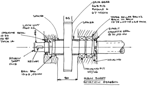
Figure 5.3Initial Sketch for Major Parts of a Rotation Gearbox [1]
Sketching is a fairly low-level method of graphical communications and is extremely useful for assisting in the visualization and formulation of possible solutions to design problem. The use of sketches is not restricted to design problems, however; visual representation may be very useful in other areas—for example, as a precursor to analytical problems. When working out stresses in beams, the situation can be clarified by a neat sketch. In some cases the development of beam analysis requests neat sketches so that shear-force diagrams and bending-moment diagrams can be created. These are just some of the instances where sketches can be used to enhance the development of a solution or communicate to another party.
Sketching is a low-level communication device and its use should be avoided for direct inclusion in professional reports, since inclusion often reduces the professional impact, perhaps giving the reader the wrong impression.
5.5.2 Layout drawings
Layout drawings are created after the sketch stage. Layout drawings are prepared at the design stage by the designer, who has calculated elements such as bearing sizes, seal sizes, and gears. These items are then applied to scale to the overall assembly. These drawings lay out the item mechanism or assembly so that each item can be annotated with component sizes, designation, tolerances, sizes, materials, and other information required to enable draftspeople to prepare detailed drawings.
When designs were prepared and drawn by hand on a large drawing board, these layout drawings were an important step in the process. Often a designer would prepare a layout drawing and pass it to a draftsperson. Commonly the designer would complete the detail drawings personally.
The application of digital drawing packages has changed the process and improved the speed of drawing preparation. In many cases the layout drawing can be bypassed altogether, but some complex designs still require the clarification offered by layout drawings. Figure 5.4 shows a part of the layout drawing created from the sketch in Figure 5.3.
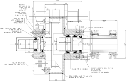
Figure 5.4Part of a Layout Drawing for a Rotation Gearbox Showing Major Components [1]
Figure 5.4 shows the major gearbox components in context and to scale. Annotations show tolerances, specifications for the bought-out components, and all manner of detail that would be required to create detail drawings.
The advent of 3-D modeling has changed the process. Figure 5.4 was created on a 2-D drafting system, but the individual component outlines were copied to be recreated as 3-D models. This may be considered a long-winded approach, since many 3-D systems allow direct creation of components without referring to the layout stage of the design process. The choice of process and method of creating the models depends entirely on individual preferences and the complexity of the design.
5.5.3 3D modeling
Humans tend to see objects and components in three dimensions. Three-dimensional modeling has allowed engineers to communicate much more efficiently by creating accurate 3-D images. Three-D models are able to be expanded, reduced, turned around on the computer screen, sectioned, and colored, as well as many more options that enable the human designer to better understand the shape and function of the component. The gearbox shown in Figure 5.4 was assembled with a group of 3-D components. The gearbox casing is shown in Figure 5.5.
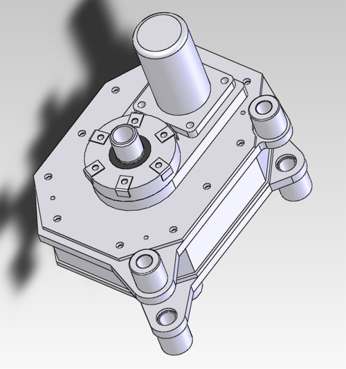
Figure 5.5Three-Dimensional Model of a Rotation Gearbox Case [1]
Three-D components and assemblies digitized as models can be forwarded to clients via e-mail; then, using suitable viewing software, the clients can view the proposed design. The sharing of designs and other information has now become an almost instantaneous paperless activity, with the great advantage that such communication can now be global. Designers are no longer restricted to designing in a location next to the manufacturing facility; they can now design in, say, the United States and e-mail manufacturing information, in the form of digitized drawings and models, to a manufacturing operation in South Korea.
The digitization of a proposed component or assembly allows it to be stored as a computer file. These files can be loaded into specialist software to perform complex analytical operations such as finite element stress analysis, dynamics analysis, thermal analysis, and fluid flow prediction using computational fluid dynamics (CFD) techniques.
These powerful tools have been developed principally as a result of the digitization of components and can perform multiple calculations per second that a human designer would find impossible to complete. The result is to give the designer a powerful means of performing accurate calculations and analysis and predicting the performance of components to a level and accuracy hitherto unknown. These tools also speed up the design process, since components can be assembled within the computer environment, saving time and cost. A prototype may be assembled digitally before any metal has been cut. It has been said that designing assemblies in this fashion can reach between 80% and 95% of the complete prototype before any metal has been cut.
Compare this to the design process that created the Avro Lancaster WWII bomber, which required drawings to be produced on paper so that a team could build the prototype aircraft. The completion of the design prior to the prototype build was probably as low as 50%, thus creating an enormous cost in terms of redrawing, redesigning, and manufacture of new parts.
Three-D modeling, along with the associated tools, has expanded the design function so that time to market and therefore cost have been dramatically reduced. For instance, the time required for a vehicle to be manufactured from the concept stage in the 1960s was about five years. Digital design techniques have much reduced that time to market to perhaps 18 months to two years.
The Filter Tilter shown in Figure 5.6 was designed and digitally modeled prior to the manufacture of any components. It was estimated that the design was 95% complete prior to manufacture.

Figure 5.6Digital Assembly 3-D Model of the Filter Tilter [1]
5.5.4 Two-dimensional modeling
Two-D modeling is a modern term given to the production of two-dimensional drawings. Historically, 2-D drawings represented every component, every subassembly, and the general assembly. A 2-D detail drawing has to be as technically accurate as the component it represents. The technique of drafting has grown, by necessity, to be a very precise method of describing the shape and size of components. It is subject to precise standards such as British Standards BS8888 or the American Society of Mechanical Engineers (ASME) Y14.2, Y14.3, and Y14.5.
5.5.4.1 Detail drawings
Detail drawings, sometimes called manufacturing drawings, usually show a single component and give all the information necessary for the manufacture of that component. The items these drawings should specify are:
• The form or shape of the component
• Full dimensions, tolerances, and surface finish
• Specific material designation, heat treatment, and the like
• Machining instructions and processes
5.5.4.2 Assembly and subassembly drawings
Assembly and subassembly drawings are essentially the same thing. However, an assembly drawing is of a discrete product, such as a pneumatic bollard. A subassembly is an assembly of parts, such as those in an internal combustion engine, which are destined to be part of a much larger assembly, such as a passenger vehicle.
An assembly drawing shows an assembly of parts and specifies how the whole component is assembled. The drawing should show the finished product with all the parts assembled in their correct relative positions. This is done by producing the drawing in such a way as to show how adjacent parts fit together. Sometimes an assembly procedure is stated. Certainly assembly instructions such as “Grease shaft before applying seals” should be stated on the drawing, as should other similar instructions. It is beneficial to add overall size dimensions and perhaps specify the position of parts relative to some datum.
5.5.4.3 General assembly drawings
A complicated product such as a passenger vehicle is made up of several subassemblies, such as engine, the vehicle body, seats, suspension, and the like. The general assembly drawing is an assembly of all the subassemblies, showing their location within the overall product.
5.6 General Drawing Application
There is a great deal of responsibility laid on the draftsman or the designer. A lack of concentration on someone’s part may mean that the wrong size is set down on the drawing. This could translate down the line to the component not fitting and needing be scrapped, which of course is costly. A grave mistake could be made, perhaps of inserting a weaker specification of material on the drawing than that which is actually required. For example, the chain anchor on a rock drill mast lifts the rotation gearbox out of the ground, along with tonnes of drill string. On one occasion this chain anchor was specified on a drawing as 070 M20 (mild steel). The designer had requested a much stronger alloy steel. The consequences were that the chain anchor was weak and snapped in service. The 3,000 kg of gearbox and drill string crashed down the drill rig mast, narrowly missing the driller. This was a close call and could have ended in a fatality.
Two-dimensional drawings can be generated using a 3-D CAD package. Once the component is modeled in 3-D, the software can semiautomatically generate the drawing. The drawing usually needs attention from the designer, who will arrange the views, dimensions, and tolerances so that the drawing is a true and accurate representation.
An example of a complete detail drawing is shown in Figure 5.7. This is the rotation gearbox shaft, part of the gearbox shown in Figures 5.3, 5.4, and 5.5. We can see that it possesses all the detail necessary to manufacture the shaft. Attention to detail is absolutely paramount for this application, since a missing dimension or perhaps an omission of material specification, surface finish, tolerances, or the like could lead to at best the item being scrapped or at worst a component failure leading to a fatality.
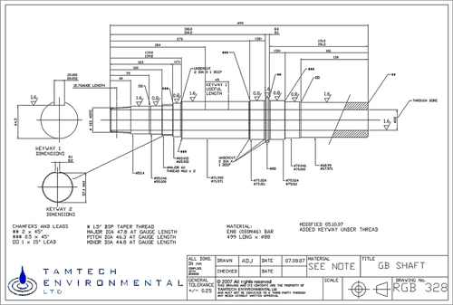
Figure 5.7Detail Drawing of a Rotation Gearbox Shaft [1]
Our discussion of 2-D drafting has thus far covered detail drawings, but other types of drawings, such as assemblies, can also be represented. Figure 5.8 shows the general assembly of the Filter Tilter, showing each labeled component and its location and interaction with other components. The assembly drawing is often perceived as a picture that in reality is a pictorial assembly instruction. Often assembly procedures are specified on the drawing along with components required to assist in assembly. Such assembly-assist items could include grease to assist the assembly of bearings and seals, specialist tools, jigs, and other small items such as end plugs to prevent dirt ingress into hydraulic pipes.
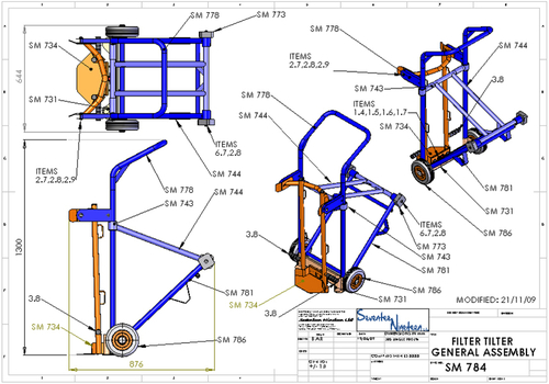
Figure 5.8General Assembly of the Filter Tilter [1]
5.6.1 Drawing practice basics
5.6.1.1 Information clarity
The whole point of creating a drawing is to impart precise, technical information to a third party. With this in mind, the draftsperson must ensure that the drawing is clear and unambiguous. U.K. and U.S. standards have been devised around this principle. The skill of the draftsperson is to create a drawing to a drawing standard so that it can be read and understood by another person who is also familiar with that drawing standard. Producing a drawing to a drawing standard can be likened to speaking the same language. It should be noted, however, that within the drawing standards there is scope for individual styles by different draftspeople. A drawing of a component produced to the same standard by one individual will convey the same information but will be a very different drawing than that done by another individual.
5.6.1.2 Orthographic projection
Orthographic projections are 2-D representations of 3-D objects. Features of 3-D parts are presented on a flat plane, as though the outlines of the part had been projected onto a screen. Figure 5.9 illustrates the principle.
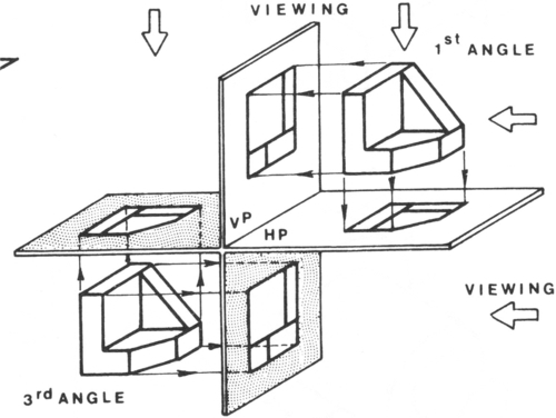
Figure 5.9The Principle of Orthographic Projection [2]
The viewing angles are split into quadrants of first angle, second angle, third angle, and fourth angle, as shown in Figure 5.10.
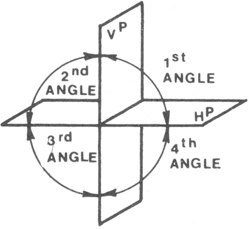
Figure 5.10The Quadrants Used in Orthographic Projection [2]
In practice only first angle quadrant and the third angle quadrant are used since these are pure views. The second angle quadrant and fourth angle quadrant are combination of first and third angle projections and cause confusion to the reader.
The principle of first-angle projection is shown in Figure 5.11. Here the viewer looks at the 3-D shape and projects the image onto a screen behind the component.
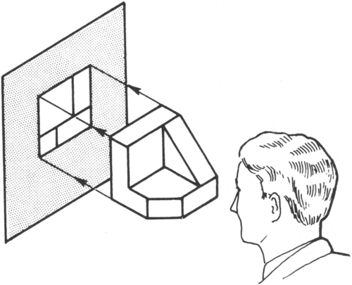
Figure 5.11The Principle of First-Angle Projection [2]
The principle of third-angle projection is shown in Figure 5.12. Here the viewer looks at the 3-D shape and projects the image onto a screen in front of the component.
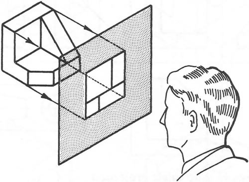
Figure 5.12The Principle of Third-Angle Projection [2]
The difference between the two projections might seem trivial. However, there are great advantages in using third-angle over first-angle projection. In third-angle projection, the view of a component is drawn next to where the view was taken. In first-angle projection, the view is drawn on the other end of the component, at the opposite end from where the view was taken. Figures 5.13 and 5.14 show the differences using an example of a large ship’s gun barrel.
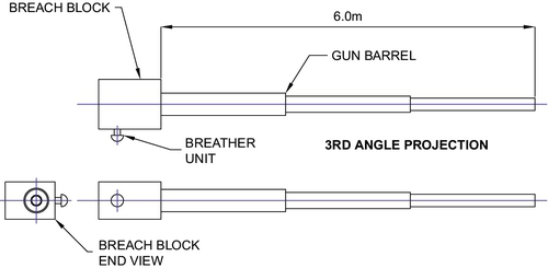
Figure 5.13A Gun Barrel Drawn to Third-Angle Projection [1]
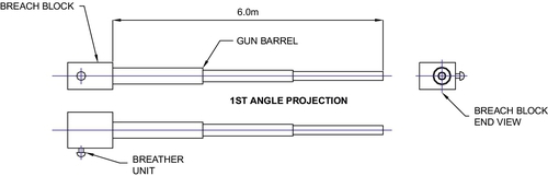
Figure 5.14A Gun Barrel Drawn to First-Angle Projection [1]
In the case of 3rd angle projection the breach block end view is drawn at the same end as the breach block. Conversely in the case of first angle projection the breach block end view is drawn at the opposite end of the gun barrel to the breach block.
In the case of small components, first-angle projection might not present any difficulty, but small components tend to be fitted to larger components and subassemblies, which can require a third-angle projection approach. Convention therefore dictates that draftspeople do not mix projection angles in the same subassembly. The normal projection tends to be third-angle projection for all drawings, from subparts through general assemblies. Though first-angle projection is still included in the standards and is still used in some industries, it is the least popular of the two preferred projections.
5.6.1.3 Views and sections
It is normal for the component to be represented in at least three elevations. These are usually:
• Front elevation
• Side elevation
• Plan (overhead view)
Depending on the complexity of the component, these views may be expanded to include others as required to achieve clarity. The selection of the other views depends on the skill of the draftsperson, who selects the most appropriate views that most efficiently describe the component. Sometimes a simple component can be described with just two views and perhaps a section, as shown in Figure 5.15.
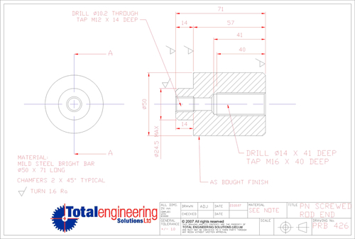
Figure 5.15A Detailed Drawing of a Rod End Showing Two Views, Incorporating a Sectional View [1]
Components can be very complex, requiring an inside view for a full explanation. Sections are often taken to reveal this view. One of the conventions the drawing standards require is that dimensions must always be placed on an outline. The only method with which to lay bare internal structure of a component is to take a section. This may be a complete section of the component or it may be a scrap section or an auxiliary view. Figure 5.15 shows a simple component requiring only two views for its full explanation. This is a classic example of a component in which the internal shape is more complex than the external shape and therefore requires a section for its full explanation. Figure 5.16 shows an assembly drawing of a pneumatically actuated bollard. This is a full section, which allows the fitter to “see” the internal components and their positions.
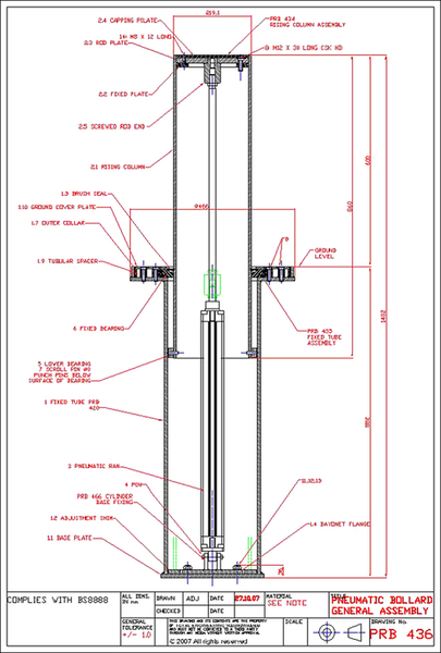
Figure 5.16Sectional View of a Pneumatically Actuated Bollard Assembly [1]
5.6.1.4 Hidden detail
Hidden detail is very useful to show internal features of a component but should be used sparingly, since it does not show the depth of a feature. Furthermore, if several features are shown with hidden detail, the view becomes very complex and the reader is unable to decipher which feature is which. In such a case, it is better to take several sections so that each feature is shown individually and can be referred to using section planes shown on other elevations of the drawing. The confusion brought about using hidden detail to show multiple features is the main reason the drawing standards prefer dimensions to be drawn from solid outlines, that is, sections.
5.6.1.5 Dimensions
A drawing without dimensions is merely a picture. The outline of the component shows the “shape,” but the dimensions define its size and convert the picture into a technical drawing. There are two types of dimension:
• Size dimensions
• Positional dimensions
5.6.1.5.1 Size
Every feature on a component needs to have its shape defined by size dimensions. It is important to note that these size dimensions need to be applied in all three dimensions, that is, in terms of:
1. Height of the feature
2. Width of the feature
3. Depth of the feature
5.6.1.5.2 Position
Every feature a component must have its position defined by position dimensions. It is important to note that these position dimensions need to be applied in all three dimensions from a datum, that is, in terms of:
1. Position in the depth of the component
2. Position along the width of the component
3. Position within the height of the component
Figure 5.17 shows a simple cube in which two holes have been machined. In dimensioning such an item, we should treat the component feature by feature.
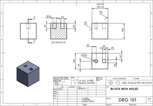
5.6.1.6 Size dimensions
External component size: Height, depth, and width entered at 150 mm for each element stop
Circular hole size: Height, 50 mm; diameter, 30 mm
Square hole size: Height, 50 mm; width, 30 mm; and depth, 30 mm
5.6.1.7 Positional dimensions
There are two features, the circular hole and the square hole:
1. Circular hole position. Two positional dimensions, from the edge of the block to the center of the hole, position the hole in two dimensions. The third dimension is given by the depth of the hole.
2. Square hole position. Two positional dimensions are shown, from the edge of the block to the edge of the hole. The third dimension is given by the depth of the hole.
We can see that sometimes positional dimensions and size dimensions become one and the same. The depth of each hole, for instance, becomes a combined size dimension and positional dimension.
5.6.1.8 Dimensioning strategy
As with writing reports and other documents, dimensioning strategy needs to consider who will be reading the technical information displayed on the drawing. Dimensioning strategy will change from industry to industry, but nevertheless, dimensioning should be tuned to manufacturing personnel who directly translate those sizes and positions to the component.
Sheet metal workers will require not only cut sizes but also position of bend lines. Foundry personnel (pattern makers in particular) will require component sizes plus an extra thickness to account for casting tolerances, draw angles, and so on. The dimensions for a machined component will need to take into account how that component is to be held in the vice or chuck. Figure 5.7 showed a shaft that requires machining.
We see from Figure 5.7 that the dimensioning strategy has been developed so that the machinist (turner) can turn the shaft from one end while holding the other end in the lathe chuck. This has been achieved by creating a datum at each end of the shaft. The turning tool will cut from right to left, finishing at the flange. Some measurements will be taken from the right-hand shaft end along the length of the shaft toward the chuck. When one end of the shaft has been completed, it is merely turned round so that the machined end can be inserted into the chuck, allowing the machining process to be completed on the unturned end.
Attention is also drawn to the method of dimensioning the keyway. U.K. and U.S. keyway standards indicate the depth of keyway is taken from the upper surface of the shaft. In practice this surface is machined away and is an impractical dimension for the machinist to measure, since there is no material from which to measure. Instead the machinist will use a vernier gauge or micrometer to measure the distance between the bottom of the keyway and the diametrically opposite surface of the shaft. It is therefore incumbent on the draftsperson to calculate this dimension and insert it into the drawing.
The approach to dimensioning is to give the artisans numerical dimensions that can be directly applied to the component. The artisans are often in a dirty environment and are ill equipped to perform calculations and conversions while at their machine tools. It is the draftsperson who has the means and is in an environment that is conducive to performing these calculations and manipulations. The aim is to allow the components to be manufactured efficiently while reducing mistakes due to poor information.
5.6.2 Other information for complete drawings
5.6.2.1 Tolerances and surface finish
Sizes are only part of the story of making the drawing into a true technical representation of a component. Dimensional accuracy requires tolerances, and with tighter and tighter tolerances come the requirement for smoother and smoother surface finishes. The shaft in Figure 5.7 and the cube in Figure 5.17 both possess toleranced dimensions with the incumbent surface finish specification.
It is important to realize that tolerance and surface finish indicate a machining process and should be carefully applied. A tight tolerance cannot be achieved with a very rough surface finish where the surface roughness could even be larger than the tolerance. Specific tolerances are usually inserted on critical dimensions such as diameters, which house bearings or seals. The title block of a drawing normally has a general tolerance. This is a tolerance that applies to all the dimensions on the drawing that are not specifically toleranced. It should be as generous as possible but is specified to keep the overall dimensions within reasonable bounds.
The quest for accuracy generally means tighter tolerances and smoother surface finish. Unfortunately, tighter tolerances incur exponentially, increasing machining costs. For example, a shaft turned to a diameter of 50 mm has a tolerance of:
ϕ50.00 / 50.11 mm,
Surface finish 1.6 Ra (1.6 roughness average)
These sizes specified to two decimal places generally mean that the machining process is to be a turning operation.
If the tolerance is now specified at:
ϕ50.000 / 50.111 mm,
Surface finish 0.8 Ra
the specification to three decimal places means that the machining process is now specified to be a cylindrical grinding operation. This also means that the cost has quadrupled compared to a turning operation.
The lesson here is that tolerance accuracy and its application on the drawing may lead to enormous increases in component cost. The designer or draftsperson must continually ask the question, “Do the tolerances really need to be so tight?”
5.6.2.2 Center lines
Center lines denote a circular feature such as a shaft or a hole. A rectangular feature seen on an elevation of a drawing could be identified either as a circular feature or a rectangular feature. The center line is the method of quickly identifying the shape.
The sectional view of the cube in Figure 5.17 shows the two hole features. In that particular view, the only way the circular hole can be identified is by its center line. If the center line is removed, the two features are identical. The shaft shown in Figure 5.7 is also shown with a center line. If the center line were not present, convention suggests that it should be considered to be a rectangular cross-section.
In the reading the drawing, clarity dictates that center lines should always be entered on circular features.
5.6.2.3 Material specification
There are many other features that should be included on a drawing because they are essential for manufacture. One of those is material specification. This must be a specific material designation, such as:
EN (070 M20): Low-carbon steel (a version of mild steel) used for general-purpose steelwork
EN8 (080 M46) (AISI 1040): Medium-carbon steel, usually used for shafts
EN24 (817 M40) (ASTM A1011): High-strength steel, used where strength and low weight are important
The correct designation of material on the drawing specifies that material exactly. If general terms such as mild steel or aluminum alloy are inserted, it leaves the choice of material open to guesswork by well-intentioned manufacturing staff who probably do not have a grasp of the end use of the component and are therefore ill equipped to select appropriate material.
5.6.2.4 The title block
The title block houses information such as drawing numbers, title, scale, author, date, revisions, and other data essential to making the drawing complete. This element of the drawing is just as important as the outline of the component, since it gives background information and source information. The drawing number is the key to the designation of parts and its position in the overall assembly. Without the drawing number, the component would be lost in a jumble of parts. Examples of title blocks are shown in Figures 5.7 and 5.17.
5.6.2.5 Text and formal lettering
Drawing standards set out the preferred standards for text and numbering. They take into account the size of text compared to the size of the drawing sheet, the style of the text and its clarity, and whether the text is handwritten. In the days before CAD, when many drawings were hand-drawn on large drawing boards, the text was also handwritten; however, most CAD systems now offer a variety of fonts and the ability to change font size and style.
On occasion it is still necessary to write on drawings by hand. On such occasions it is useful to adhere to the appropriate standards. Figure 5.18 is an extract from the American National Standards Institute (ANSI) that indicates the style and size of handwritten lettering.

Figure 5.18Drawing Standards Applied Lettering Convention [3]
5.6.3 Drawings checklist and common errors
It is useful to check through the drawing to make sure all the data is present. To this end, here we include a general checklist.
5.6.3.1 Title block and border
• Border
• Component title
• Drawing number
• Date
• Author
• Material specification
• General tolerance
• Scale
• Dimensions (in mm/inches)
• Revision/modification number
• Drawing angle 3rd/1st
5.6.3.2 Overall drawing
• Dimension to suit the machining method
• Dimension: Critical dimensions
• Dimension: General dimensions
• Dimension: Features
• Size of each feature in three dimensions
• Position of each feature in three dimensions
• Angle dimensions
• Specific tolerance: usually located with a critical dimension
• General tolerance
• Geometric tolerances
• Annotations: Always use capital letters
5.6.3.3 General drawing instructions
• ϕ diameter symbol: Designation of diameter dimensions
• Center lines: Designates a round feature
• Surface finish marks: Usually located near a critical dimension
• Cross-hatching: Designated sectioned area
• Scrap sections
• Section reference planes: Position of cut line for sections
• Welding marks: Designates weld type/style/position/method/size
5.6.3.4 General remarks often found on drawings
• References to another drawing if a view is on a separate drawing; e.g., another view on a different drawing
• Ballooned parts numbers should specify components on assembly drawings
• Remove sharp edges
• Unless specified, all surfaces to have the following surface finish: _____
• Unless specified, all welds to be as follows: _____
• Unless specified, _____
5.6.3.5 Oft-repeated convention errors
Please don’t make these mistakes!
• Cross-hatch webs
• Cross-hatch round objects
• Cross-hatch bought-out components
• Dimension to hidden detail: Use sections or scrap sections
• Dimension to the end of shafts; confusing
• Dimension diameters as a radius; machinists work to diameters
5.6.4 Drawings: common errors
5.6.4.1 Dimensioning
• Keyways are depicted in a particular way as shown in Figure 5.19. Dimensions depicted in this way will allow the machinist to measure the feature and compare a direct measurement to the dimension.
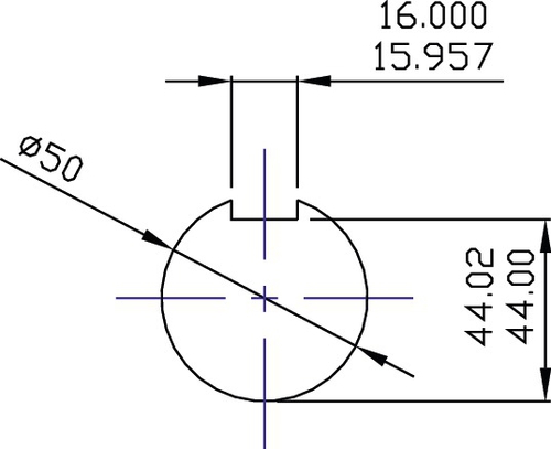
Figure 5.19Dimensioning and Measurement of a Key Way [1]
• Avoid tolerance buildup by dimensioning from another dimension, as cumulative tolerances will lead to dimensional errors.
• Dimensioning to three places of decimals, e.g., 24.987, forces the machinist to work to those fine limits. Give the machinist the largest tolerances possible. Ask yourself, “Do I really need the dimension this tight?”
• Apply dimensions to features that the machinist can directly measure.
• Dimension diameters, not the radius of a shaft. The machinist can directly measure diameters.
• Do not dimension to end views of shafts. It is confusing and does not help the reader understand the information. See Figure 5.20.
Figure 5.20Dimensioning to the End of Shafts Leads to Confusion [1]
• Dimension 38.97. Round it up!
• Ensure that all relevant dimensions are on the drawing—PCDs and sizes and positions of features.
• Check component size in three dimensions and feature position in three.
• Tapped holes: Ensure tapping drill size and depth are given as well as tap size and depth.
• Dimension to suit the manufacturing process—e.g., turn a shaft from both ends because the shaft has to be held in a chuck on the end that is not being machined.
• Dimensions referring to diameters should be preceded by the diameter symbol ϕ. Dimensions without this symbol will be treated as rectangular.
• Assembly drawings: Include overall sizes and/or scale. Without these items the size of the component is impossible to determine.
• Ensure that arrowheads can be seen. Match the size of the arrowhead to the size of the text.
• If you draw arrowheads by hand, they should be blocked in with a ratio of 1:1/3. See Figure 5.21.
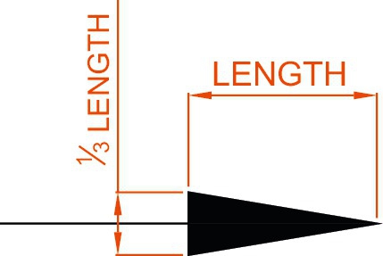
Figure 5.21Preferred Arrowhead Ratio [1]
5.6.4.2 Drawings: general
• Circular features require a center line. This line must be visible; therefore, AutoCAD yellow is not sufficient because it cannot be seen when printed.
• Each component must be drawn on a separate drawing, complete with a unique drawing number.
• Heat treatment has to be specified on the drawings. It can be specified to a particular hardness or a particular stress level. This needs to be applied in conjunction with steel type used.
• Do not cross-hatch shafts or webs.
• Avoid drawing small outlines on a large sheet of paper. Fill the paper, either by reducing the paper size or increasing the scale of the outline.
• Ensure that scales are correct as specified on the drawing. Sometimes CAD systems automatically apply a scale.
• Title blocks: Use them. They include important and useful data.
• Use standard sizes of screws, e.g., M8, M10… but not M9. There is no such size.
5.6.4.3 Materials
• Specify materials exactly using the appropriate designation! A general material description of “Steel” or “Brass” is too broad.
• Often cast iron is specified. Gray cast iron is brittle in tension and cracks in cold weather. Select an appropriate cast iron, such as spheroidal graphite cast iron, which has the strength of mild steel. UTS 320MN/m2.
• Materials: Use medium-carbon steel EN8 (080 M46) for the shaft and mild steel (070 M20) for general steelwork applications.
• Use hidden detail sparingly; otherwise, it becomes confusing.
• Use scrap sections in preference to hidden detail. These are clearer because the depth can be seen.
5.6.4.4 Parts lists
A parts lists must include the following:
• Part number
• Quantity
• Description
• Material and cut-off sizes
• Drawing numbers
• Bought-out part numbers
• If bought-out, the supplier
5.6.5 Allocation of drawing numbers
Drawing number systems vary from project to project and from company to company. Every drawing should be allocated with a unique drawing number. The drawing number may be a pure number, perhaps computer generated or a combination of alphanumeric characters. The possibilities are so vast that only a general overview can be given here.
The drawing number for a totally computerized system may be of the following order:
01-12345-02
This number may be unintelligible to someone outside the company, but fed into a computer it can be very precise. Often drawing numbers possess a sequence that has meaning for practitioners who work with the drawings. The number may reflect a client or a general assembly or a subassembly and finally a part and subpart, as shown in Figure 5.22.
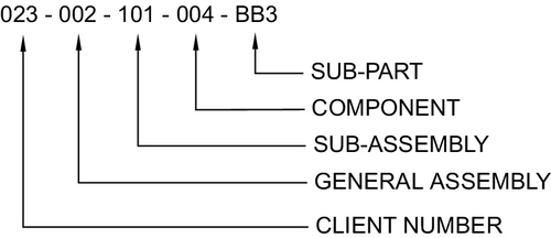
Figure 5.22Example of a Drawing Number [1]
• Subpart: This is an item such as a web that will be part of a fabrication, creating a full component.
• Component: This could be a welded fabrication assembly. In the case of an engine, it could be the cylinder head block or the crank shaft.
• Subassembly: This is an assembly of parts that form a discreet product, such as an internal combustion engine. This will eventually be fitted to a much larger assembly.
• General assembly: This is a “map” that shows where the subassemblies fit on a large assembly. The whole assembly of a product such as a passenger vehicle is split into convenient elements, which are the subassemblies. A subassembly may be a suspension system, a rear seat, a wheel hub, or an internal combustion engine. The general assembly brings the whole of the subassemblies together.
On a smaller design, the drawing number may be much simpler, such as that shown in Figure 5.23. The drawing number shown in Figure 5.23 is much simpler in that it shows the designation for the project, the particular subassembly, and the component.
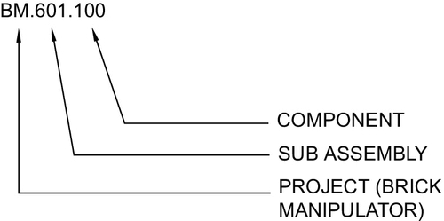
Figure 5.23Alternative Drawing Number [1]
Drawing numbers may be so simple that they may be merely a number. This depends on the complexity of the assembly. An uncomplicated drawing numbering system is shown in the example parts list shown in Figure 5.24. These drawing numbers are typically of the style:
PRB 435
PRB represents the project, which is a pneumatic rising bollard (PNB), whereas the number 435 is merely the next drawing number in the sequence.
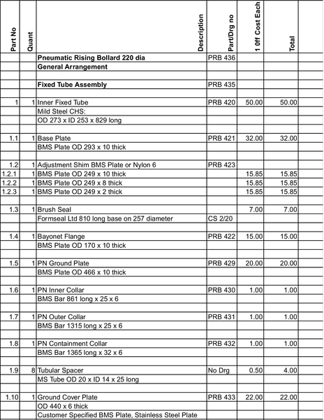
Figure 5.24A Typical Parts List [1]
Sometimes the efficiency of the build is dependent on how the drawing number is designed. The drawing number should possess certain elements that are known to the manufacturing and design personnel. Ideally the drawing number should have the attributes described in the following sections.
5.6.5.1 Must-have attributes
• The drawing number should be unique.
• It should normally follow an intelligible sequence.
5.6.5.2 Desirable attributes
• Indicate the project type
• Indicate the customer
• Indicate the subassembly
• Indicate the general assembly
5.6.6 Parts lists
Parts lists have many names. They may be called bills of materials, component lists, or inventory lists. A parts list is created by the design department as the designs are created and parts and components are specified. The most obvious function of the parts list is to itemize all the parts required to build up an assembly, but its real task is to act as a build itinerary and a guide to the various functions (e.g., purchasing department, planning department, manufacturing, accounting department) that are required to manufacture the product.
The parts list is the key with which to identify components and cross-reference drawing numbers, parts numbers, and material specifications. Of all the documents that make up an assembly of parts, the parts list is probably the most important. Without the parts list, the cross-referencing of materials and components cannot take place. The parts list provides the background information to key together all the disciplines required to manufacture the assembly.
A parts list must contain:
• A complete list of parts
• A list of subassemblies
• A physical description of parts and raw materials
• Drawing number designations
• Links of part numbers to drawing numbers
• Links of parts numbers to bought-out components
Throughout a manufacturing company, various disciplines contribute to the final creation of the product. Each will use the parts list in a specific way, as itemized in the following sections.
5.6.6.1 Purchasing department
Purchasing uses the parts list as a shopping list, sourcing all the bought-out parts and raw materials that will eventually be manufactured.
5.6.6.2 Planning department
Planning uses the drawings and parts list in combination to organize the progress of the components through the works. After considering all the machining processes required for each component, the planning department allocates manufacturing time for each station and plans the progressive manufacture of each component through the final stage of assembly.
5.6.6.3 Manufacturing department
Manufacturing uses the parts list to identify subassemblies and link raw materials to components while planning work schedules for manufacturing personnel.
5.6.6.4 Accounting department
Accounting allocates material costs and labor costs against each part and eventually completes a cost analysis against each subassembly. In this way a costing model can be compiled.
5.6.6.5 Contents of the parts list
As we’ve shown, the parts list is used by several departments that will apply their own information. It should be noted that the design, drawings, and eventually the parts list are generated in the design office. It is incumbent on the designers to apply certain information that the other departments can use. This general information is as follows:
• The part number
• The quantity required
• The name or description of the part
• The material from which the part is to be made
• The overall size of the raw material
• The designation of bought-out parts such as bearings, seals, motors, and the like
• The contact details for suppliers of bought-out parts
A typical parts list is shown in Figure 5.24. Many of these details are present here, but in this case costs have been added so that a total cost can be tallied.
5.7 The Client
Depending on the type of project, the client could be a large institution, such as a government or a multinational company. The client may also be an individual for whom the designer is acting as a consultant. Most designers work for institutions between these two extremes.
5.7.1 Large institutions
Large institutions tend to issue large, high-value projects that are bound by rules and penalties set out in a contract. It is normal practice for the client and the design team to name liaison officers who routinely meet and share regular updates, ensuring that checks are in place and that stage deadlines are being met.
This system of checks is important because clients on the contract often offer stage payments. For example, the contract might suggest that once the concept has been presented and accepted by the client, a payment will be made to further the development process. In such a case, the liaison between designer and client is likely to be formal in terms of shared reports and weekly or monthly meetings. It is very likely that appointed liaison officers will be in informal, regular contact through e-mail or telephone.
5.7.2 The individual client
Depending on the type of project, the communication process between client and designer could be either very formal or very informal. It is likely that communication between client and designer would occur through e-mail, phone calls, and personal contact. Progress reports are unlikely to be as formal as with the large institution; however, regular contact is absolutely essential. It is likely that between an individual client and the designer or design team, there must be a great deal of trust. If communication fails, human nature suggests that the client will naturally assume that the project has faltered and his project funds are being squandered. This type of client requires constant reassurance.
5.7.3 The medium-sized client
Most designers will be involved in projects that are supported by their own company. Communication therefore is often between colleagues within the same design team and on similar levels based on the client’s team. Often the task of formal communication with the client is left to the design team leader and may be organized on a formal basis. In such projects, however, it is important that communication is established at lower levels, between members of the client team and the design team, so that technical information can be shared.
5.7.4 Client requirements
No matter what the project, the basic requirements for the client are a willingness to fund the design and development of a product or service. Projects vary in size and require different approaches. The institutional client will require a great deal of formality and formal reporting; the individual client may want to have input into the design process. The detailed involvement of the client can either be very helpful or counter-productive.
For example, in the design of a bed-lifting device, discussed in earlier chapters, the design of the folding leg at the foot of the bed became a major design issue simply because the client was never satisfied with the eight different options that were put forward. The design team was heavily constrained by the lack of fixing points and the visual impact of the leg when raised to the ceiling. The problem was solved when a fresh approach was applied by external designers responsible for the aesthetics of the device.
In other areas of the design, the client was extremely helpful, but this particular point illustrates the problems that can arise when a client becomes closely involved in a project. In the longer term, client involvement may cost more than if the client simply accepted the design team’s suggestions.
5.7.5 The Client’s wishes
One of the most difficult parts of a project is always the beginning, when the designer is attempting to understand the requirements and constraints. The client could actually make this process more difficult, since he will have his own ideas as to how to solve the design issues, even though he might not be a specialist. In such a case the designer has to develop an attitude whereby he will absorb all information but then step back and take account of what is required. It is easy to be led by the client to a solution that might not work. In such instances it is useful to write down a list of requirements and constraints.
For example, an individual client (a small company) requested that a designer design a simple pneumatic press that would cut out double-sided adhesive tape into heart shapes. The double-sided adhesive tape was to be used to build up a soft three-dimensional heart to be placed on the front of a Valentine’s card. Several layers of fabric, card, and foam were to be combined using the double-sided sticky-tape heart shapes.
The client described the type of machine required and much of the technical details, such as airline pressure, physical size, controls, and the like, and had even allocated a space for the machine once built. It would have been a simple task for the designer to design the required press; however, the designer took a “mental step back” and considered what was actually required. The designer set out a list of requirements and constraints as follows:
Requirements:
• Throughput speed: 10 units per minute
• Low cost
• Combine parts using adhesive
• Assembly performed within the factory environment
• Assembly performed by one person
Constraints:
• Personnel safety (adhesive vapor inhalation)
• Dexterity of personnel in assembly
• Perform assembly within the factory environment
• Cost
It can be seen that in writing down the requirements and constraints, there is no obvious requirement for a pneumatic press. The client was focusing on what he could apply to solve his problem rather than focusing on the real problem, which was, “How do I glue these components together?”
The key to the solution was the third requirement, “Combine parts using adhesive.” The correct isolation of the problem led to the use of a pressurized spray adhesive. This evolved into a solution that was much lower cost than the pneumatic press and had more efficient throughput of over 20 items per minute.
In conclusion, it is true to say that sometimes the client does not know what he needs to solve his problem. The designer’s skill and self-discipline allow him to step back from the problem, possibly ignoring the client’s suggestions so that he can identify the real requirement.
5.7.6 Project requirements
Whatever project is undertaken, the client has employed the designer or the design team as specialists who can solve a particular design problem. The designer must evaluate each project by considering many conflicting requirements. Some of these requirements are:
• Technical requirements
• Cost requirements
• Market requirements
• Production requirements
• Sustainable requirements and possibilities
The contradicting nature of some of the requirements may require constant feedback to the client so that the direction of the project is as the client wishes. For instance, say that a design team has been tasked with designing a lean-burn internal combustion engine with very low emissions. The sustainability requirements are such that the cost increases. Liaison is required with the client to ensure that the increased cost direction of the project can be sustained by the client.
As a design progresses, the use of new materials and processes increases the likelihood of unseen costs. Communication liaison channels are therefore required to keep the client informed of new developments on the project.
5.7.7 Presentation of designs
The presentation of a design depends on the stage of the project and the formality required by the client. An institutional client will probably require stage feedback, but at certain points during the project, such as at concept stage, the client might want to have an independent body scrutinize the design before signing the approval document, thus allowing the project to continue. In other less formal arrangements, the client might merely want to see the concept design in terms of 3-D models for drawings or perhaps as a product specification. At the end of the design-and-build cycle, the commissioning of large items such as a ship is dependent on a formal report from the shipping line. This would normally happen before the final payment.
5.7.8 Styles and methods of presentation
There are many and varied styles of presentation, as this chapter has explained. The presentation needs to be tuned to the understanding of a particular client. The client may have a team of specialists, in which case the presentation should cater for the main points of the design as well as its more technical and cost elements, to which the experts on the team will be receptive.
The presentation could take many forms, contingent on the client’s requirements. Any presentation will most likely require a verbal presence accompanied by a visual slide presentation or even posters, reports, or the like. On another level, the presentation may also involve the prototype.
Whatever the design or the presentation process, the designer needs to possess multiple skills, not only in engineering design but also as a diplomat and an expert communicator.
References
[1] Author supplied: designs and drawings from the authors' commercial and teaching experience.
[2] O. Ostrowski, Engineering Drawing with CAD Applications, Butterworth Heinemann, 1989
[3] American National Standards Institute (ANSI) cross referred to BSENISO5457 (1999).