
Design for Total Control
Abstract
This chapter covers the practical steps that can be used to ensure that the SLV (sustainable Life Value) of a design is optimised. It covers developments and ideas in material sourcing, efficient material usage, design for minimum lifetime energy consumption, ease of maintenance and prolonged life. It also considers end of life disposal within the parameters of the waste hierarchy.
The role of the engineering designer grows more and more complex with every passing year. There are more duties and constraints built on this role than any other role involved in the development of a product. The designer or design function must be creative, must produce a conceptual product that has to fulfill the market needs, must design it in such detail that it can be manufactured, and, while all this is taking place, the designer has to consider how to keep the cost of the product low. Recent years has seen the designer take on more roles, especially where the environment and sustainability are concerned.
Traditionally designers have designed equipment and manufacturers have built it. This is no longer possible since there are so many demands placed on the design function that the designer now has to take total control of the whole life of a product, from sourcing materials to disposing of the product at the end of its life.
7.1 Traditional Approaches
Design for manufacture has been a theme of designers for many years, but the demands and expectations placed on designers of new products mean that the scope of the design function has to be expanded. There has always been a drive to reduce the creation costs of products. Indeed, cost reduction of new products is a primary objective for designers and manufacturers alike. A quote from an anonymous industrialist defines the problem: “Everything costs money.”
Recent years have seen a growing emphasis on providing products that are environmentally friendly (that is, sustainable). It is a fact that many businesspeople, designers, and manufacturers consider this effort an expensive enterprise, but in reality the design and manufacture to sustainable values and requirements often lead to lower-cost production.
7.2 The Sustainability Umbrella Model
The traditional design and manufacture goal of designing to cost has now been joined by the need to design and manufacture for sustainability. The quote from the anonymous industrialist can be enlarged as follows: “Everything costs money, and everything has an environmental impact.” Perhaps this idea can be redefined as:
• All new products cost money.
• All new products “take” from the environment.
• All new products therefore need to be developed for low cost and high sustainability.
Sustainability and low cost often go hand in hand. It can be argued that products designed with sustainability as one of the primary objectives can also be designed under an umbrella of sustainability covering all other facets of the design process. Consider the sustainable whole-life model previously put forward and now shown in Figure 7.1.
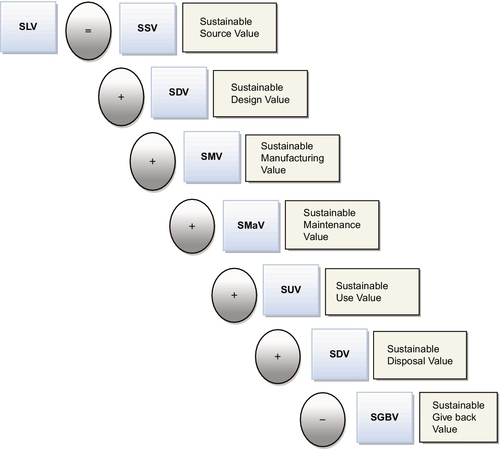
Figure 7.1Sustainable Whole-Life Model [5]
Design for manufacture has been a constant element within the design process for many years, but the demands and expectations placed on new products mean that the design function has to be expanded further.
7.3 Total Design Control
Any manufactured product will have used a certain amount of energy in its manufacture; this energy could be derived from several sources. For instance, much of the energy could be derived from fossil fuels, which can be considered synthetic energy and will possess a carbon footprint. Increasingly, the energy used in the creation of a product will be derived from a renewable source such as hydroelectric or wind or solar energy. These sources can be considered natural energy.
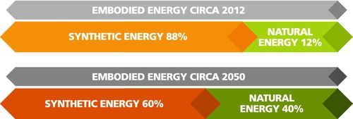
Energy is required whenever a process is applied to a material. A finished product has had expended on it a certain amount of energy, which is normally considered to be embodied energy [14]. This value of energy is a combination of synthetic energy and natural energy. The embodied energy diagram in Figure 7.2 indicates the likely proportions of synthetic versus natural energy within the embodied energy of a product [1, 2].
It is important that the embodied energy value is quantifiable. Since every aspect of the design and manufacture of a product demands that energy is applied, it seems that a value of energy per process is an appropriate measurement value. This complicated process has been much simplified by Granta Design Ltd. of Cambridge, U.K., which has created a very sophisticated software tool that calculates the embodied energy at various stages of a product’s development [3].
We can see from the sustainable whole-life model in Figure 7.1 that the overall design of a product requires a whole-life approach and can be achieved in its entirety by the designer or the design team. Furthermore, the designer must not design in isolation. The designer or design team has to be in control of all aspects of the design, from instigation through manufacture and in some cases marketing. This, then, is total design control.
7.4 A New Design Approach (The Umbrella of Sustainable Design)
The traditional design and manufacture goal has always been to design to a cost, but recent years have seen this model being joined by the need to design and manufacture to sustainability values. The general perception of design with sustainability as a criterion is that it is an expensive process. The truth is that any product will be expensive if created with inefficient or ill-considered processes.
Any product that is brought to market has had energy applied to it in the form of manufacturing and other processing activities. This then gives the product a value of embedded energy. If the value of embedded energy could be reduced, so would the cost of processing. A reduction in embedded energy is also a major goal of design for sustainability and is therefore symbiotic with a desire to create products at a low cost.
The design and manufacture process should now involve both:
• Design for low-cost product creation
• Design for sustainable product creation
Products designed and created with sustainability as the primary objective can be generated under the umbrella model of sustainability, which encompasses all the facets of design and manufacture.
Consider the sustainable whole-life model shown in Figure 7.1. This can be used as a guide to show the elements that the designer needs to consider and that are set out in the sustainable design objectives model shown in Figure 7.3.
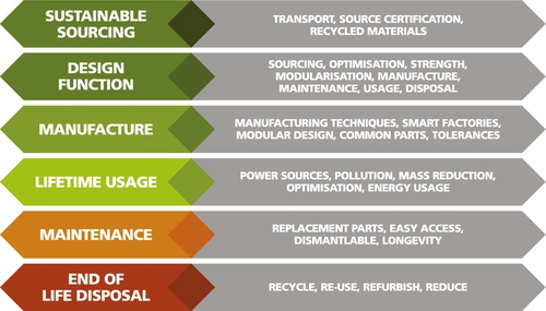
Figure 7.3Sustainable Design Objectives Model [5]
Applying sustainability techniques at each of the stages in the sustainable design objectives model ensures that all sustainability and cost requirements are present in the final product. These requirements include already standard design requirements such as efficient manufacturing and low manufacturing cost.
The application of the sustainable whole-life model in conjunction with the sustainable design objectives model ensures that the designer controls the whole design process and in doing so includes all the design objectives, old and new, that are required of a new product. The great advantage of adopting this model is that the designer can oversee the whole process, integrating appropriate procedures and techniques throughout the life of the product. This integration will, in turn, create appropriate efficiencies.
7.4.1 Sustainable sourcing
It is important that the designer can specify and control the raw material he intends to use in the new product. Raw materials need to have their sources identified, and for the designer to quantify the value of sustainability (embodied energy), this source identifier requires the embodied energy value applied to the raw material. This may seem a tall order, but the process is already in place in several industries.
The aircraft manufacturing industry, for example, requires a certificated origin of materials that are sourced for consistency in strength, leading to safer components. Materials from a noncertified source may at first be suitable but may prove unreliable, since they might not comply with purity requirements, chemical composition requirements, or strength requirements.
One example of this scenario is where wing root pins (pins that hold the wing to a plane fuselage) were found to be cracked. After following the trail back to the material source through the certification process, it was found that the material origin was an unreliable source and documents had been forged. This was clearly a breach of safety procedure and resulted in legal prosecutions. This case may be safety oriented but shows that sourcing procedures and certification are already in place out of necessity.
Another example is that of the sourcing of timber used in street furniture. This timber is used on external wooden walkways, wooden bollards, and seating on street benches. This timber may also be used as decorative elements on other street furniture such as litter bins. The materials are used in an outdoor environment where the temperatures may vary from –20 °C to + 50 °C. Rain may lash the timber, or perhaps it may suffer an extended dry period. Timbers such as oak, ash, pine, and sepele would disintegrate within a very short time if placed in such environments. The best material for this purpose is iroko, a very sturdy and durable mahogany grown along the west coast of Africa.
When refurbishing urban environments, U.K. local councils specify iroko only when there is a certificate declaring that the timber is from a sustainable source. This policy clearly warrants that retailers, importers, and growers ensure that the product is sustainable or they would simply not make any sales.
Once the system has been established for other materials such as steel, rubber, and plastics, designers could specify materials, confident that they would be from sustainable sources and would have a minimal impact on the planet’s resources. This would then be part of designers’ control over selecting those raw materials certified with a certain sustainable source value (SSV).
7.4.2 Recycled materials
Recycled materials are gleaned from products that have come to the end of their life. Energy is required to convert the recycled material into a usable raw product, but this energy use is likely to be a fraction of the energy used in obtaining the commodity from an original source.
The remaining rubber in used vehicle tires is removed from the tire using a grinding process, resulting in a recyclable granulated rubber. This raw material can be applied to many different products, from road speed humps to soft children’s playground floors. Though it requires energy to convert the recycled material into new products, there is notably less energy expended compared to obtaining the original material and transporting it across the globe to a factory.
Recycling for many materials is already the norm. Some of the more common recycled materials are:
• Steel
• Rubber
• Glass
• Plastics
• Building materials
• Wood
Many products combine differing materials, creating difficulties in later separating those materials for recycling. Such products include passenger vehicles and computers. However, emerging techniques enable useful pure materials to be extracted from such products. It would be helpful to the end-of-life disposal engineer if material separation was a feature built in at the design stage. This is already being achieved in the passenger vehicle industry, where designers aim for a recycled value of 95% of the vehicle.
For designers to take advantage of recycled materials, those materials must be made available in a pure form, with a certificate of authenticity showing the embedded energy value. This certification would allow the designer to control the sourcing of recycled raw materials so that he could quantify the SSV.
7.4.3 Reduction of haulage dependence
It is inevitable that the goods will have to be transported. Raw materials require delivery to manufacturing centers, and new products need to be shipped to their point of sale. Haulage of goods can never be eliminated, but certain measures can be taken to reduce the embedded energy required in that transportation.
To understand why materials have to be transported, it is useful to roughly categorize particular materials and the reason for the transport. The breakdown of categories of transported materials is as follows:
1. Materials that are created near their extraction point, such as aluminum, timber, or certain foods such as coffee, tea, and wine.
2. Materials and products that are manufactured overseas and imported and that could include such items as passenger vehicles, golf bags, motorcycles, lawnmowers, and barbecues.
3. Those items manufactured in a particular country, then exported.
These activities will always be present; indeed, the prosperity of some countries is based on export and import of goods and other raw materials. The energy used in transporting these goods will always be required, whether generated from an artificial source or a natural source. In many cases the appropriate application of sustainable methods will reduce the dependence on artificial energy in favor of naturally generated energy.
Consider those materials in paragraph (1) where there is no alternative but to transport the materials, often globally. The appropriate application of sustainable methods would apply natural power such as that used in the past by sailing ships. In past centuries these were used to great effect and were completely sustainable, since they relied on natural wind power rather than the artificial power derived from, say, diesel engines.
In the modern era, when the convenience of diesel power overshadows many other options, employing natural energy such as that used by sailing ships may seem implausible. However, some enterprising companies are offering systems that supplement diesel power for ships with sails and solar collectors [3.6, 3.7]. Some short over-water voyages are powered completely using solar collected power. Such is the case with Eco-Marine Power, which operates a ferry service across Hong Kong Harbor [3.6].
These initiatives can greatly reduce the emphasis on carbon-fueled transport but require quantifying and certification so that embodied energy values are available to the designer. This system would put designers in control by offering them the means of selecting materials with the lowest environmental impact.
Now consider imports and exports outlined in points the earlier (2) and (3). Many consumer items are manufactured overseas, often because the cost of doing so is very low. Typically, many consumer items are manufactured in the Far East countries such as China, Japan, and South Korea, then shipped to destinations such as Europe and the United States. Unfortunately this enterprise does not usually consider the environmental cost of transporting the goods.
As the tendencies of recycled commodities become more the norm, materials may be gleaned from local sources, reducing transport costs and environmental impact. Appropriate certification with values of embodied energy can then quantify the sustainability value of a product. This system will give designers much more control, since they will be able to select appropriate materials and thus manage the environmental impact within their particular design projects.
This method not only gives designers control over material selection, it encourages other beneficial aspects. The use of local materials and local labor leads to improved local economies. Although it is inevitable that the goods will have to be transported, certification of these goods and the measurement of embodied energy enable designers to take control of the material selection element of the design, thus improving the SSV while promoting local prosperity.
7.5 The Sustainable Design Function
The design function is the only function in the entire product creation process that has a total overview; as such, it has the power to influence the whole process. Traditional design and manufacturing models tend to isolate the design function from the manufacturing function. Indeed, the manufacturing function has often dominated the whole process, and it is suggested that these isolated functions lead to inefficiencies in cost and sustainability. Corbett and Dooner [4] suggest that 70% to 80% of manufacturing costs are defined at the design stage. It should be noted that this estimate is for manufacturing costs only. As has been shown, manufacturing is only one element of the whole product life process.
The sustainable design objectives model shown in Figure 7.3 outlines the general elements for which the design function is responsible. However, certain aspects of design influence many other elements throughout the whole-life model and can only be considered at the design stage. The design considerations are as follows:
• Sourcing
• Optimization
• Strength
• Modularization
• Manufacture
• Maintenance
• Usage
• Disposal
Some of these elements will be considered later in more detail, but it is incumbent to discuss several of these aspects since they are a pure design function. Such elements as optimization, strength, modularization, and maintenance should be considered at the design stage, since they influence processes, usage, and expedience of disposal in later stages of the product’s life.
Whenever a design is created, there has to be an element of optimization. In some cases this could be an exercise in selecting the best compromise. For instance, there is always a compromise between adding mass and adding strength. An aircraft requires strength, but it also requires low mass. Aircraft designers always have to deal with the compromise between the requirements of high strength and low weight.
Optimization is a technique whereby the designer creates a product that is tuned for a particular purpose. A vehicle designer may design a particular vehicle for high speed, in which case it will possess the following qualities:
• High-performance engine
• Streamlined shape (high-speed aerodynamic profile)
• Two-seat capacity
• High-performance suspension and tires
• Low profile
• High-performance gearbox
The same designer could also design a particular vehicle for driving in a congested urban environment, in which case the vehicle will have the following attributes:
• Low-speed performance engine
• Low fuel consumption
• Low-speed aerodynamic profile
• Two-plus-two passenger capacity
• Maneuverability for parking
The two vehicles may both have the usual elements, such as engine, four wheels, passenger compartment, and brakes, but they will be optimized for very different uses, resulting in very different vehicles.
The optimization process can become extremely complicated, often using statistical analysis to effect the best optimized design. In this book we outline a more simplistic approach aimed at understanding the process to achieve more practical aims.
The brief for a new design sets out the requirements and, through investigation, the product design specification is formulated. The designer may not be consciously aware, but she will have exercised design optimization. Design optimization is present in every design, to a greater or lesser degree. Its function is to guide the design so that its performance is tuned for a particular purpose.
A cantilever lifting device, for example, was originally intended to lift small pallets within a factory environment. It was manufactured as an all-welded construction with cantilever arms that were 20-mm-thick plasma-cut fabrications. In this industrial situation, the designer did not perform stress analysis to the cantilever and consequently overdesigned the component. This was a case of “If it looks right, it is right,” and it fell into the trap of overdesign because humans generally overestimate. The lifting device was optimized for use in a factory environment, however, where there is plenty of space and noise is not a problem.
These optimized parameters are acceptable in a factory where noise, finish, and size would not normally be a problem. Manufacturing the unit for domestic use is much more likely to be a bolted assembly, so that components can be maneuvered through small spaces such as stairways and doorways and into bedrooms.
An entrepreneurial businessman had the inspired idea of adapting the same device for use as a bed-lifting device in studio apartments. The lifting device was therefore optimized so that it would lift a bed to the ceiling and as such could be used in bedrooms to create living space during the day and sleeping space during the evening. Though the lifting mechanism was the same, there were very different parameters to the two constructions. The list of optimizations follows:
• Assembled by two workers in four hours
• Components should be light enough to be lifted by one person
• Components should be small enough to be carried upstairs and fit through doorways
• Assembled on-site in a bedroom environment
• The mechanism had to be low noise
• The finish had to be 100% domestic (as you would expect a finished product to be in your own home)
Though the general principles of the industrial device were used on the domestic bed, there was a great deal of optimization required, since it had to fit the preceding list of parameters. A schematic of the bed-lifting device is shown in Figure 7.4.
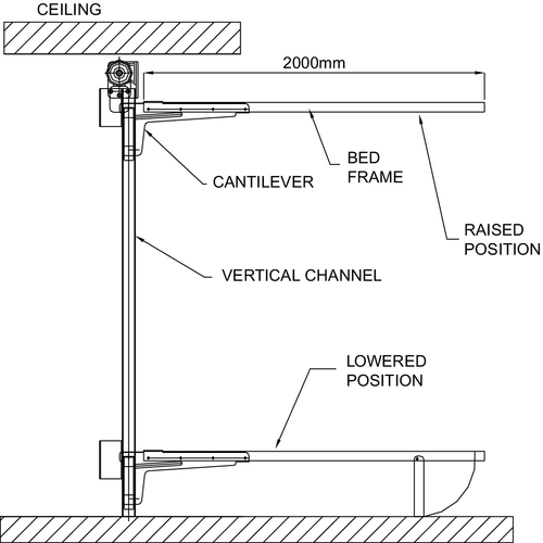
Figure 7.4The Bed-Lifting Device Optimized for Bedrooms [5]
Many optimization elements can be applied to a new product or an old product that is being rejuvenated. The particular optimization goals depend on the type of product and its end use. Figure 7.5 gives a very general selection of optimization goals related to typical products.

Figure 7.5Product Types and the Major Optimization Approaches [5]
We can see from the chart that low mass, low cost, and sustainability can be applied to all of the products. Low mass and low costs are standard design parameters, but sustainability has many facets and can be subdivided into the elements shown in the sustainable design objectives list in Figure 7.3.
The chart in Figure 7.5 is merely an example of optimization goals applied to familiar products. In reality, a major optimization goal should be set. Minor optimization goals will automatically contribute to the major goal.
7.5.1 Optimization strategy
Design optimization is almost always a multicriteria design approach in that several aspects of the design are optimized to achieve the main optimization goal. The strategy should be to define the major optimization goal and utilize several minor optimizations to achieve the major goal.
For instance, the major optimization goal for a touring motorcycle would be that of rider comfort. To achieve this goal, there would be minor optimizations to apply to the design. Figure 7.6 indicates how these minor optimizations contribute to the major optimization goal.
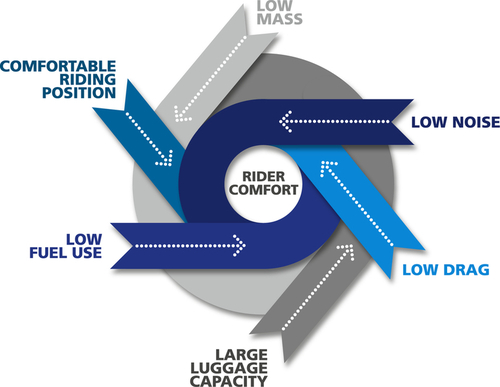
Figure 7.6Minor Optimization Goals Contributing to the Major Optimization Goal of Rider Comfort for a Touring Motorcycle [5]
It should further be noted that even the minor optimization goals may be further subdivided so that, for instance, the goal of low fuel consumption may involve redesigning the engine or selecting an alternative engine.
Optimization tunes a product for a particular use and in so doing filters out many irrelevancies. For instance, a vehicle optimized for urban use would tend to have a smaller engine than one developed for high speed. The smaller engine would therefore suit the environment in which it was meant to function and would have minimal irrelevancies that would consume extra resources.
In tuning a product for a particular function, savings can be made throughout the life of the product and could involve savings in sourcing, manufacture, usage, maintenance, and disposal. Optimization therefore minimizes embodied energy and contributes to the sustainable whole-life model in Figure 7.1.
7.5.2 Strength
Many products require strength to some degree in order to perform their designed duty. For example, a teapot requires strength in the handle and the ability to stay rigid while a person is carrying hot liquid in it.
Some devices. However, require in-built strength in order to perform safely. In these cases the consequences of failure could be fatal. An excellent example is the roof structure shown later in the chapter in Plate 7.2, the strength of which is critically important in ensuring the safety of the audience seated beneath. Another example is that of an aircraft wing, which requires strength no matter what extremes of use. Failure in flight would lead to fatal consequences.

Plate 7.2Football Stadium Roof Structure [2]
During the design of such devices it is necessary to perform structural analysis to ensure that appropriate strength is built into the structure so that it can perform its design duty. Modern analytical tools allow design engineers to calculate the performance of devices with high accuracy, eventually leading to the reduction of material without compromising strength. Furthermore, the flexibility of such tools gives designers the opportunity to devise more complex and stronger structural shapes, further reducing material content. The analytical approach using such powerful tools now allows designers to promote radically new designs and apply innovative process methods.
The development of the passenger vehicle body is an excellent example of the application of this process. A vehicle manufactured in the 1950s normally comprised a chassis and a separate body. The body material was manufactured from relatively thick steel sheets, which made the vehicles rather heavy compared to their modern equivalents. Though various components of vehicles are made from different thicknesses of sheet metal, typically the sheet metal used in body panels in 1950s vehicles was around 1 mm thick. Reduction in vehicle mass in modern vehicles has been achieved by clever design to give appropriate strength but mainly because of reduction in material thickness, which in current vehicles is typically around 0.75 mm.
The old-style chassis design incorporating a separate body has been replaced in modern vehicles by the structural element becoming the car body itself. Even the windscreen is a structural element in modern vehicles.
Though this section of the chapter predominantly deals with strength and structures, it should be remembered that other areas of engineering are benefiting from digital analytical prediction, including:
• Dynamic analysis
• Mechanisms analysis
• Fluid flow analysis
• Thermal analysis
Previous chapters suggested that humans tend to increase structural size “just to be on the safe side.” This approach is commonly known as a “rule of thumb” and increases factors of safety above those that are necessary. This approach classically adds mass but relieves the designer of performing precise prediction analysis. Applied correctly, hand calculations verifying digital analysis allow precise prediction of performance, reducing safety factors, reducing mass, and more important, reducing the embodied energy required to process the material. In terms of vehicles, a low-mass body requires a smaller engine and smaller brakes, resulting in lower fuel consumption—a suitably sustainable approach.
Reduction in mass can also be achieved using a uniform stress technique. Many easily accessible components, such as structural steels, are supplied as a uniform section simply because it is easier to manufacture uniform sections. A typical example of a 100 mm × 200 mm rectangular hollow section is shown in Figure 7.7.
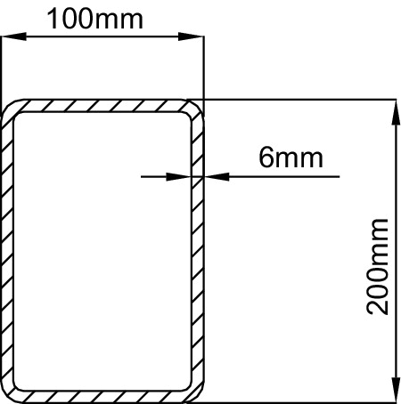
Figure 7.7A Typical Example of a Uniform Section, 100 × 200 mm(Rectangular Hollow Section) [5]
A simple beam, however, has little bending stress applied to the support points, whereas in the middle there are high stresses, perhaps because of applied loads from above. An example of the beam supported at each end and loaded by a point load in the center is shown in Figure 7.8. The figure also includes a bending moment diagram, which is essentially a graphical representation of the loading across the beam. We can see that the greatest bending moments, and therefore bending stresses, can be found toward the center of the beam. There will obviously be stresses at the support points, but the bending moment and therefore bending stresses are very low.
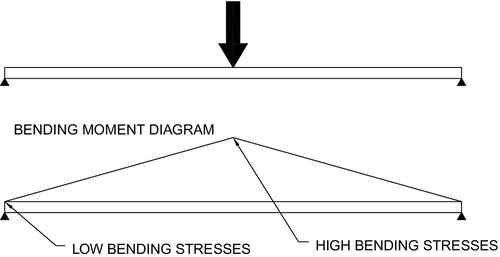
Figure 7.8Typical Simply Supported Beam with Central Load Showing Bending Moment [5]
It seems reasonable, therefore, to apply material where the stresses are highest. In the case of the beam, the greatest strength would be required at the center of the beam. Though it may seem appropriate to increase material where there is high stress, the subtle approach would be to increase the “depth of section.” In general beam theory, the greater the distance between the top and bottom surfaces of a beam, the stronger the beam becomes. This can often be achieved with only a small percentage increase in material. If the depth of the section is increased where the loads are highest, such as at the center of the beam, it follows that the depth of section can be much reduced at the support points.
The bridge shown in Plate 7.1 is essentially a beam supported at each end. The weight of the beam is applied as a uniformly distributed load (UDL). The bending moment for this type of loading is shown in Figure 7.9. We can see that the greatest stresses are applied toward the center of the beam, so this is a nonuniformly stressed beam in which stresses are higher at the center.

Plate 7.1Typical Fabricated Foot Bridge [5]
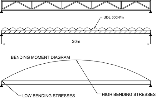
Figure 7.9Typical Bending Moment for a Beam with a Uniformly Distributed Load [5]
In a uniformly stressed design, the material and hence the depth of section are applied according to the value of the stresses in the beam.
The theory presented so far is that of a beam designed to encounter nonuniform stresses between the support points. Material on a standard section B is therefore wasted toward the support points, where there are very low bending stresses. If, however, the beam were to be designed so that the stresses between the support points were uniform, the shape of the beam would change so that it would have a greater depth of section in the middle and a lower depth of section toward the support points. This design feature has been used successfully on many occasions. A classic example of this uniformly stressed design approach is that of a particular football stadium roof structure, shown in Plate 7.2.
The loadings applied to such stadium roofs take the form of UDLs incorporating such loading elements as settling snow, heavy rain, and winds. It is, however, a structure that follows fairly closely the assumed typical bending moment by applying a greater depth of section and therefore strength toward the center of the beam. Though the ends of the beam at the support points also require strength, the stresses are different from those applied to the center of the beam, and therefore a smaller depth of section can be applied.
This kind of technique can reduce material usage, though it may marginally increase the embodied energy required to manufacture.
Uniformly stressed beams can be used to great effect when large quantities of items can be produced. A classic example here is that of a digger backhoe (see Plate 7.3), which can be treated in one mode of operation as a simply supported beam and which possesses a near uniformly stressed sectional design.

Plate 7.3Classic Digger Backhoe [6]
The backhoe’s secondary arm that supports the bucket is wider at the head, where the hydraulic ram and pivot are located, than at the bucket end. Though there are significant loads applied to the bucket end, the major bending moments and therefore high stresses are at the ram and pivot locations. Rather than use a standard section beam, parallel for its full length, manufacturers have created a deeper section where the highest stresses are located and tapered the section toward the bucket, where there are lower stresses.
Manufacturing costs for a single-unit production could prove very high for this type of fabrication, since components would need to be cut to shape and welded. A much cheaper option would be to use a standard uniform section such as that shown in Figure 7.7. Backhoes are manufactured in quantity, however, which means that the cost of creating a particular shape is outweighed by the saving in materials over hundreds of units.
The great advantage of structural analysis to define the strength of the structure is that the appropriate strength can be applied without overdesign or including excessive material “just in case.” The whole process is based on a scientific process rather than a “rule of thumb” approach, which wastes material and often leads to excessive energy use in the building of the product. The analytical approach therefore offers a safe product with a minimal embodied energy value, thus contributing to the sustainable manufacturing value (SMV).
7.5.3 Modularization
Traditional design methods design and manufacture a single product, but in markets where the product has different end uses, it is necessary to effect changes to the product without starting the design from scratch. The key to this conundrum is to design and build different elements of the product separately. This modular design method is an approach that subdivides the product into smaller components (modules) that can be independently created and applied so that the end result can be used in different ways. A modular system can be characterized by the following:
• Partitioning of a product into discrete scalable, reusable modules. Each module consists of isolated, self-contained, independently functioning elements.
• Rigorous use of well-defined modular interfaces, which could include mechanical, electrical, or software interfaces.
• Connection or attachment interfaces designed for ease of assembly, and where possible use of industry standards for key interfaces should be applied. These key interfaces could include standard electrical or computer sockets and plugs, standard flange sizes for pipes, or industry-standard locators such as those applied to vehicle wheels or motor flanges.
Modularization offers flexibilty without the need of customization. Modules are often mass produced, offering low-cost production and a great deal of flexibility in design. It is also possible to easily add new solutions in the form of new modules. A great example of modular design and manufacture is that of passenger vehicles. One of the reasons the cost of passenger vehicles is kept relatively low is because a great deal of modularization is applied. A vehicle body may be produced for a premium vehicle type, but with a different modularized engine, upgraded brake modules, paint, badges, and modular interior, the vehicle can be converted into, say, a sporty version. This flexibility can be achieved without returning to the beginning of the design process.
Modularization can also be applied across vehicle marks. Chassis, brake components, engines, tires, wheels, and many more components have all been used across vehicle types and across vehicle makes.
One of the classic uses of modularization, and one that transformed vehicle manufacture, was that of the design of the Mini, which was first released in 1959. Alec Issigonis designed the modular chassis and body system to improve manufacturing and increase space inside the vehicle. The concept consisted of three major elements: a front subframe, a rear subframe, and the vehicle body. The front subframe housed the engine, drive shafts, brakes, and suspension; the rear subframe supported the rear suspension and brakes. The real design breakthrough was that the vehicle body was used as the chassis structure. This was probably one of the first production instances of the application of a monocoque design, which incorporated the vehicle body as the structure. The cleverness of this design approach was in the modularization of major components. Figure 7.10 outlines the configuration of the subframe modules and vehicle body for the Mini.
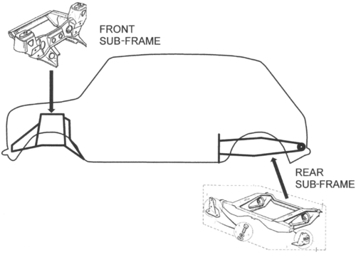
Figure 7.10Diagram of the Mini and Approximate Positions of the Front and Rear Subframes [5]
In a more modern concept car, Thomas Budde Christiensen [7] reported that General Motors developed the Chevy Volt. The main vehicle architecture is taken from the Chevrolet Cruz and the Saab 9-3 in a classic case of modularization across vehicle makes. The innovative modularization concept behind the Chevy Volt is that there is a selection of three different propulsion options:
• A pure battery electric motor option
• A combined electric combustion engine option
• A combined electric fuel cell option
There are other modular devices that have been incorporated, such as wheels that are driven by their own internal motors and batteries that can be charged from a variety of sources. Chassis modules are shown in Figure 7.11.
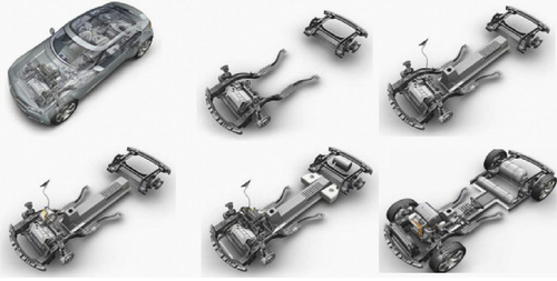
Figure 7.11Chassis Modules for the Chevy Volt [6]
Modularization is used extensively in computers, buildings, railroad signaling, and many other products. The bed-lifting device shown in Figure 7.4 is also a modular construction. Standard parts can be bolted together using small modular components that are interchangeable. The drive unit, which fits against the wall, becomes one standard base module. The bed sizes, which may change, are manufactured as modules so that queen, king, double, and single beds can be accommodated for a particular order. This modularization greatly reduces the organization and energy required to manufacture while still preserving the flexibility to serve customers’ requirements.
Under normal circumstances, high-volume manufacture reduces the individual cost per item. This is one of the great benefits of standardization. Modular-build systems effectively standardize larger systems rather than just smaller components, thus reaping cost advantages of large-volume production. In a similar fashion, modularization also reduces the embodied energy in each package. If modules are mass produced, they are more efficiently produced, therefore demanding less embodied energy input and consequently having a lower environmental impact.
One of the most heavily modularized products in the modern world is the computer, which is designed to accommodate modules. A standard base unit comprises power supply units, processes, motherboards, graphics cards, hard drives, optical drives, and so on. All these parts are interchangeable and can easily be replaced if, for instance, there is a damaged graphics card or an upgrade is needed to allow higher functions to be gained from a more basic computer.
A similar approach has been taken to software provision. A computer with an appropriate level of memory and speed can be “tuned” using appropriate software. For instance, the computer hardware may be exactly the same for professional use as for home use, but a computer intended for computer games will have a different set of software than the computer intended for use by a design engineer. Similarly, an engineer using his computer for internal combustion engine data acquisition will have a completely different set of software than that for home use or for engineering design.
Modularization has been used for many years and to great effect. The use of modules reduces cost and allows easy maintenance due to quick replacement of modules. Refurbishment of modules is therefore possible, prolonging the life of the main product. Thus we can see that the use of modular construction fits well within the model of sustainability and improves the SMV.
7.5.4 Manufacturing
Manufacturing is the most expensive part of the product development process. It involves the procurement of materials, their manipulation, and their finish, to various degrees. This process usually takes place in a factory of some kind using machine tools, labor, and energy. The cost of providing this facility can be enormous.
It is the designer’s role to design components and products that the factory can manufacture, but too often the design and manufacturing model has been separated into pure design and pure manufacturing. This can lead to great inefficiencies in terms of cost and wasted energy.
Even if design is separate from manufacturing, the designer must consider manufacturing during the design process. For instance, the designer must decide whether to fabricate or cast or whether to mill or turn. Corbett and Dooner [4] suggested that 70% to 80% of the production costs are defined at the design stage. With this in mind, it is useful to define the elements that contribute to efficient manufacturing and which are often built into designs automatically. These elements are worth itemizing here:
• Minimize total number of parts
• Develop modular design
• Use standard components
• Design parts to be multifunctional
• Design parts for multiuse
• Design parts for ease of fabrication
• Avoid different fasteners
• Minimize assembly directions
• Maximize compliance
• Minimize handling
7.5.4.1 Minimizing the number of parts
A reduction in the number of parts normally leads to a reduction in handling, a reduction in inventory, reduced background paperwork, reduced number of drawings, and so on. Generally a reduction in parts creates a simpler product with much less energy expended and, normally, reduced costs. Even though numbers of parts may be reduced, the functions are still required within the product. This is normally achieved by creating more efficient single-piece parts. Care must be taken, however, since there is a breakeven point at which a reduction in parts leads to complex single components that may cost more than several smaller parts.
In general, a reduction in the number of parts in a product can lead to a reduction in cost, a reduction of embodied energy, and an increase in SMV for the product.
7.5.4.2 Developing modular designs
Developing modular designs, discussed in depth in Section 7.5.3, has several advantages:
• Design flexibility
• Efficiencies of quantity production
• Easier maintenance
• Refurbishment possibilities
• Reduction in embedded energy
• Offers easy customization using combinations of standard components
• Resists obsolescence
• Shortens the redesign cycle
• Offers new generation products often using old modules
• Changes provided with a minimum of design input
• Simplifies final assembly
• Reduces the number of parts to assemble
A modular design actually reduces parts, leading to reduced costs. If applied correctly, modularization can lead to a reduction of applied energy (embodied energy) and an increase in the SMV for the product.
7.5.4.3 Multifunctional parts
The cooperation of parts that can perform several functions can often reduce the overall number of components. For instance, a structural member can also be designed as a spring, or a structural member may also act as a conductor or perhaps a heat sink. A reduction in the number of parts is always a valuable contribution, since it reduces embodied energy and improves the SMV of the product.
7.5.4.4 Design parts for multiuse
A multiuse part is a component that can perform several functions, depending on the end use of the product. For example, a mounting plate on a machine may have several location holes and captive nuts that will accommodate several sizes of electric motor flange. This mounting plate can therefore be made in quantity, thus reducing costs and improving manufacturing efficiency. An excellent example of this idea is the worm-wheel drive casing shown in Plate 7.4. This casing is manufactured from die-cast aluminum alloy and houses a particular size of worm and wheel reduction components. Though these may be standard internal components, the casing is a multiuse device that can fit a range of sizes of electric motors and internal combustion engines. Furthermore, the casing can accommodate motors from various manufacturers.
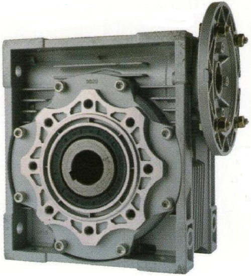
Plate 7.4Worm-Wheel Housing Multiuse Component [10]
Multiuse components offer the opportunity of reducing infrastructure costs and manufacturing components in quantity. The advantage of using such a device is that the casings can be manufactured in quantity, thus taking advantage of low cost and low embodied energy quantity production. This process greatly improves the sustainable source value (SSV) and the SMV.
7.5.4.5 Design parts for ease of fabrication and assembly:
The aim here is to reduce the time spent fabricating and assembling a product. Less time spent here will mean greater efficiencies and reduced energy input. The designer has ultimate control over the process, since he chooses the components that contribute to the overall design. When assembling a multipart product, the designer should be aware that the two major elements that need to be present for any component assembly are:
1. Parts location in three dimensions
2. Fastening method in three dimensions
Each component should be examined to ensure that location and fastening method are present. If a component is located in two dimensions, it is often possible to secure the third dimension with an appropriate fastener. Location and fastening devices can therefore work together to fully secure and locate a component. Furthermore, the designer needs to consider the following points during the design process:
• Reduce the number of parts
• Keep parts simple
• Apply modular components where possible
• Consider options of simpler assembly procedures
• Improve parts access (one-direction assembly, space for access by hands, etc.)
• Consider ergonomics for assembly personnel (fit components at reasonable heights, reasonable arms reach, etc., to reduce tiredness)
• Reduce lengthy fastening processes (e.g., screws, welding, etc.)
The assembly of a gearbox, for example, can be achieved in several ways. Large gearboxes such as those used in ships’ transmissions are often split along the line of the main shaft so that when the lid is lifted, all the gears and bearings are exposed. This means that the main shaft can be assembled with bearings, spacers, and gears prior to being hoisted into the main gearbox body. Though seemingly easy, this method has its difficulties. There is fine adjustment when tightening the lid so that bearings are not crushed, merely held in place. Precise machining and skilled fitting are required to achieve the workable result, which takes time and energy.
Another approach to assembling gearbox components is to load the shaft from one end. This method requires that one of the bearings needs to be large enough for the shaft and components to pass through its outer housing diameter. Other elements such as large gears can be loaded on the inside of the gearbox. This system requires a similar precision in machining but is much easier and quicker to assemble, thus requiring fewer parts such as shims and specialist seals. This approach not only reduces the parts inventory but also improves ease of maintenance.
Assembly is often a manual process. Any reduction in time spent on this process will reduce costs, but in a more global view it will also reduce the energy spent on infrastructure to keep workers comfortable, provide light with which to work, and all the other aspects required of a manufacturing plant. A reduction in energy here will improve the SMV.
Some assembly procedures are automated, which means that the designer cannot rely on human hand-eye coordination. When the human element is removed from the process, assembly becomes much more difficult to achieve. Consideration of assembly without human input is an excellent exercise since it focuses the mind toward the best method of assembly.
7.5.4.6 Fastening systems
Any product that comprises more than one part will require some form of fastening device. There are many fastening systems available to designers. Some of these are:
• Welding
• Brazing
• Screws
• Pins
• Rivets
• Adhesives
• Snap fasteners
• Spring fasteners
This list offers only a glimpse of available fastener types; it does serve to highlight the full range of possibilities.
The most used fastening device is probably the screw, available in many shapes and sizes. Screws require locating and rotating to be fitted properly. This is a relatively lengthy process and requires dexterity. Welding falls into the same category in that it is a dirty and lengthy process requiring much energy and time. Often these processes can be replaced by cleaner and easier-to-apply systems.
7.5.4.7 Case study: Car stacker
A three-dimensional car-parking device was to be designed according to the schematic shown in Figure 7.12. To facilitate ease of assembly on-site, the whole unit was to be supplied as a kit of parts and assembled using bolts, screws, and nuts. The deck was to be assembled from galvanized steel “C-section” units of approximately 250 mm width. The units stretched across the deck, fastening to side stringers via high-tensile screws.
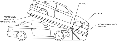
Figure 7.12Schematic of the Car Stacker [5]
When the stacker was assembled, the deck was found to flex, and although considered safe, this tended to unnerve users. The proposed solution was to stiffen the deck by fitting 0.5 mm galvanized sheet steel to the underside. Several options for fastening the galvanized sheet were proposed:
• Self-tapping screws. This would have required holes to be drilled and screws to be inserted. The time allocated for the assembly procedure was estimated at three hours.
• Blind rivets. Sometimes called pop rivets, this method still necessitated drilling holes and applying the rivets. The time taken to accomplish this task was estimated at two hours.
• Double-sided adhesive tape. This was found to be the most convenient option, with several advantages over the other methods that were considered. The time saving was enormous; it took only 20 minutes to apply the sheet steel. This was done by applying the adhesive tape from a roll and placing the sheet steel onto it, firmly pressing it in place. Not only was this method quicker, but it was much cheaper in terms of components and time and required much less energy, since no drilling was involved. Another added benefit was that the skill level required to accomplish the task was very low.
In practice, the designer had considered the flexure of the deck during the design process and had a solution ready when the flexure problem arose. He had considered screws and rivets and discarded those in favor of the double-sided adhesive tape.
When a designer considers the type of fastener to use, she may be led by current practices within her current company; however, the designer must be open to alternative thinking and reducing lengthy and expensive practices, especially if new practices can reduce the embedded energy. This approach improves the SMV.
7.5.4.8 Minimize assembly directions
Normally, smaller components are attached to a base component. Access for fitting staff and the use of automatic machines is essential for easy assembly. This can be done by minimizing the assembly directions. If personnel need to move around and assemble or have to keep turning the assembly to access assembly directions, time and energy are not being used efficiently. It is the designer’s role to ensure that assembly can be completed in the most efficient way. Usually this means minimizing the number of directions from which parts can be fitted.
This approach minimizes assembly time and reduces embedded energy, thus improving the SMV.
7.5.4.9 Minimize handling
Handling and moving components and assemblies to different positions or from one station to another are effectively dead time. No work can be carried out on the product during these periods of manipulation. This movement must be reduced as much as possible. It is in the designer’s purview to select procedures and methods to achieve this goal. Minimizing transport and handling has great benefits:
• Reducing time moving components from one operation to another
• Reducing energy
• Reducing staff time on the job
• Improving the speed of assembly or manufacture
In all of the benefits mentioned, speed of assembly is improved, cost is reduced, and, from a sustainability point of view, embedded energy is reduced. This can only improve the SMV.
7.5.5 Maintenance
A sustainable product is one whose life can be extended through maintenance and repair. During the normal process of design, maintenance should have been considered as an automatic adjunct to the creation of the design. This means that the product should be designed to be regularly maintained by replacing or refurbishing worn parts. To be fully sustainable, a product should be able to be maintained indefinitely. This latter statement is more of a wish than a reality, but there are excellent examples of products that have been maintained beyond what would be considered a normal lifespan.
The motorcycle shown in Plate 7.5 is typical of the personal transport found in countries such as India and Pakistan. It is unclear whether these motorcycles were designed and built to sustainability values; nevertheless, they are an excellent example of a product that can be maintained almost indefinitely and therefore has excellent sustainable credibility. These motorcycles are perfect for the environment in which they are used for a single rider, though it should be said that the author has personally witnessed up to five people riding on one of these machines.
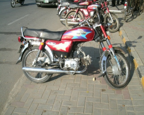
Plate 7.570cc Motorcycle [5]
The essence of the design for maintainability of the motorcycle is that parts can be accessed, removed, and replaced with a fairly simple toolkit. Another excellent example is the truck shown in Plate 7.6, which was originally built circa 1980.

Plate 7.6Truck [5]
It is typical for these trucks to be regularly maintained so that their life expectancy may be more than 50 years.
It is refreshing to note that the mindset of the mechanics who maintain such motorcycles and trucks is that of repairing or recycling components. For instance, if the aluminum crankcase of the motorcycle becomes cracked, the mechanic will recycle the crankcase by melting the material and casting another.
True sustainability has to start with the designer, who can design the appropriate elements into the product. In the case of the motorcycle and truck in Plates 7.5 and 7.6, a culture of sustainability has grown around the repair and maintenance of the machines.
As society moves away from the mindset of “throw away and replace,” a new approach will gradually take hold, which will be to make products last as long as possible. This can only happen through regular maintenance and a clear mindset of the user.
7.5.6 Usage
Whenever materials are manipulated and formed to produce products, energy is expended. For the process to be sustainable, materials need to be regenerated, applying zero impact on the environment. Furthermore, the processes involved in forming the new product need to use naturally generated energy.
Energy is required to extract materials and to build products, but in some cases the energy required to bring a product to market is insignificant compared to the environmental impact of the device in use. This is true of most vehicles and items of plant. During its working life, a digger similar to that in Plate 7.3 (this example could be any make of digger worldwide) will use much more energy than that required to create it. These devices are usually powered by diesel engines, which burn fossil fuel that can be termed artificial energy. This artificial energy cannot be regenerated by the planet and therefore is not sustainable. If the digger could be powered by electric motors whose energy is captured from natural sources, the unsustainable energy use would be changed into a sustainable energy use, thus improving the SUV.
Wherever artificial energy (diesel, petrol, kerosene) is used, there will be a large unsustainable element to the whole life view of the product.
Not all devices are unsustainable in use. A large flywheel system that stores energy will probably run for 10 years without stopping. The only impact on energy resources is in its inefficiencies relating to friction in the bearings. In comparing the flywheel to the digger, the digger possesses a very low SUV, whereas the flywheel possesses a very high SUV.
Designers must select the lowest-impact devices wherever possible. Using current technology to provide power for the digger, the best drives available are likely to be lean-burn diesel engines, perhaps using biofuels, which can be grown and are therefore sustainable. Biofuels still impact the environment, however, since they are responsible for emitting carbon dioxide when burned in an engine. Carbon dioxide is not desirable and could be much reduced as natural energy becomes more widespread as the energy of choice for vehicle power.
7.5.7 Disposal
As with all other areas of product creation, designers can control the disposal of products. Disposal can be achieved by using the 4R rule, which this section discusses in detail. The main principles are as follows:
• Reduce
• Reuse
• Refurbish
• Recycle
7.5.7.1 Reduce
Reduce probably sits more comfortably in the early design stages when a reduction in mass, size, or the like could lead to reduction in product size and a further reduction in energy consumption in manufacture as well as in product use. At the end of a product’s life, however, reduce refers to reduction in throwaway waste and therefore a reduction in waste disposal costs. It is therefore preferable to make use of materials derived from end-of-life products. The remainder of the 4Rs should therefore occur wherever possible.
7.5.7.2 Reuse
Components removed from an end-of-life product could be reused in other products. For instance, steam pipe, once used for supplying pressurized air throughout a factory, could be reused as handrail. Rolling element bearings that are removed from a product often still possess a substantial amount of life. These could be reused in less critical applications. These two examples are fairly superficial, but with a little inventiveness a designer can think beyond disposal to industries that could benefit from use components from the product.
7.5.7.3 Refurbish
Refurbishment is really a more intense form of maintenance. A well-used product is stripped down to repair major components, replace worn components, and make as new. The refurbished product exits the factory as though it were a brand-new item. Refurbishment takes a fraction of the cost and energy input of a new device and prolongs the life of the current product. This, then, has an impact on the sustainable life value (SLV) and the sustainable disposal value (SDV).
7.5.7.4 Recycle
When components are worn past any further use and it is not possible to refurbish or reuse them, recycling is the only sustainable option. The process takes end-of-life products, separates the materials, and recreates the materials as a raw material product. Steel is remelted and recast so that the steel can be used once again. Steel is actually the most recycled commodity on the planet and has a substantial recycling infrastructure.
Other commodities such as vehicle tires have to be dealt with in a different way. The remaining rubber is ground so that it can be supplied as a raw material as ground rubber pellets. Much of this material is recast as speed humps, children’s playground floors, or firing range walls.
If the end-of-life disposal is conducted efficiently, very little of any product should be taken to landfill. The reuse of materials is not only cheaper than obtaining newly hewn raw materials, but it also requires much less energy and is therefore a very sustainable practice. The designer must plan for end-of-life disposal, since doing so improves the SLV of the product.
7.5.8 Conclusions to the sustainable design function
The designer is in a unique position. It is the designer alone, or at least the design function, which can influence the whole life of a product simply by designing elements into the product to enhance certain outcomes. It is true that a major goal of design is that of maintaining low cost while the design fulfils all the functions required of it.
It is proposed that the designer needs to approach his design work with a new eye so that he can apply sustainable engineering design techniques. Many of these techniques are already well known and often used by designers to reduce costs, but they are not always associated with sustainability engineering. The modern designer should therefore design to two major goals:
• Design to a low cost
• Design to achieve a high SLV
Referring again to the sustainable whole-life model of Figure 7.1, we can see that the application of the design function can improve the sustainable value of all the elements of this model. Sustainability can only be achieved for new products via the design function. This is the only element of the whole sourcing, design, manufacturing, and marketing system that can define the sustainability value of a product.
7.6 Manufacturing
The most costly and most energy-draining part of the product creation process is that of manufacturing. The classic design-and-manufacturing model is that designers design and manufacturers make the product. Communication between the two functions has often occurred purely through engineering drawings, but in any efficient production process the two factions work together to provide an efficient product development process. Design and manufacturing should be a simultaneous approach; however, it should be realized that this is not always possible. A lone consultant designer may be very experienced but cannot be expected to know and understand all the nuances of manufacturing.
It has been proposed that the design function should be in total control of the whole product life process in creating and disposing of a product. It is such a vast task that large products should be designed by teams of specialists who can decide the best course of action for a particular aspect of the product development cycle. The specialists should therefore be expert in cross-communication with other members in the team. In particular, manufacturing specialists should liaise closely with design specialists.
A lone design consultant might want to offer his services to a particular company, which then intends to build his design. In such a case, the design consultant must liaise with key people in the various departments within the company, from procurement through manufacturing to marketing. This is really the only way efficient product creation can evolve.
Designers must consider manufacturing during the design process; they are the only people who can create the best outcome of the design. For instance, a designer must decide whether to fabricate or cast or whether to mill or turn, though this decision could be made in consultation. Corbett and Dooner [4] suggested that 70% to 80% of the production costs are defined at the design stage. With this in mind, it is useful to define the elements that contribute to efficient manufacture and that are often built into designs automatically. These elements are worth itemizing here:
• Minimize total number of parts
• Develop modular design
• Use standard components
• Design parts to be multifunctional
• Design parts for multiuse
• Design parts for ease of fabrication
• Avoid separate fasteners
• Minimize assembly directions
• Maximize compliance
• Minimize handling
7.6.1 Minimizing the number of parts
Minimizing the number of parts means that less of everything is required to manufacture a product. This includes engineering time, drawings, part numbers, material, backup paperwork, accounting details, service parts and catalogues, number of items to inspect, complexity of assemblies, facilities, and training. These are merely a few of the items that cost the company. Fewer parts will reduce costs massively. The number of parts can be reduced and reduced, but care must be taken, since the process may actually lead to creating a large single component that incorporates all the small parts but is very expensive.
Integrated design, or the combining of two or more parts into one, often decreases weight and complexity and eliminates fasteners or joints and perhaps fewer points of stress concentration. The very fact that the number of parts has been reduced has the effect of decreasing the infrastructure and support cost and effort. If these effects can be gained in reducing cost, then it follows that a reduction in applied energy (embodied energy) can also be gained.
A reduction in the number of parts in a design leads to much lower energy costs, material costs, and time to complete the product. Reducing parts therefore greatly improves the SMV.
7.6.2 Developing modular designs
Developing modular designs was discussed in depth in Section 7.5.3 and has several advantages:
• Design flexibility
• Efficiencies of quantity production
• Easier maintenance
• Refurbishment possibilities
• Reduction in embedded energy
• Offers easy customization using combinations of standard components
• Resists obsolescence
• Shortens the redesign cycle
• Offers new-generation products, often using old modules
• Changes to the product accomplished with a minimum of design input
• Simplifies final assembly
• Reduces the number of parts to assemble
Using standard components is always less expensive than a custom made item. Standard components such as screws, nuts, bearings, and seals are usually made in quantity and are often available off the shelf. This means there is little or no lead time and they are very low in cost. Standard components are easy to replace and can often be carried in a maintenance toolkit or as a maintenance package.
Since these components are made in large batches, the individual embodied energy is also very low; hence their sustainability value is very high.
7.6.3 Multifunctional parts
Multifunctional parts can often reduce the overall number of components and improve a product’s functional efficiency. Several authorities have suggested that the driver of a vehicle should not remove his hands from the steering wheel while driving, yet there are many functions that require drivers’ hands to be removed from the wheel. Most vehicles have lighting-control stalks, which are multifunction components; the stalks control headlights, main beam, and indicators and often have incorporated windscreen wiper controls, windscreen wiper speed, windscreen wash, and sometimes cruise control. This is indeed a multifunctional part built into one single stick, placed in such a position that the driver can reach the stick without taking her hands off the steering wheel. The design of this multifunction part was probably very complex but possessed obvious safety elements. This single device replaces what was formerly a bank of switches and as such is probably cheaper to produce and embodies less energy than the original bank of switches.
Components such as the lighting-control stalk can be incorporated into most designs. This is often the case in design development, but a wily designer may consider multifunction components from the beginning of the design process.
7.6.4 Multiuse parts
Multiuse parts may be used on a variety of components. A mounting plate may be designed to mount a variety of components, or a spacer can serve as an axle, lever, or the like. The key is to identify multiuse parts by sorting all parts in the design into two main groups:
• Parts that are unique to a particular design, e.g., crankshafts, housings
• Parts that are generally needed in all products, e.g., flanges, webs, bushes, spacers, gears, handles
A company manufacturing a range of similar products would normally hold their own library of standard parts that can then be used within the product range. For instance, a fabrication company manufacturing chassis for trucks might keep an inventory of parts they use on most of their chassis. These parts could include cross-beam spacers, flanges, and webs. Another company might use steel piping for compressed air lines around a factory and could use the same steel piping as walkway hand rails.
Several advantages are gained by employing multiuse components:
• Components can be manufactured in quantity, thus reducing cost.
• Designers can draw on basic components without having to redesign.
• Raw material stocks can be reduced.
• Raw material stocks can be purchased in larger quantities, forcing the supplier to give cost advantages.
In a similar way to multifunction parts, multiuse parts offer all the benefits of a reduction in components, giving ongoing benefits of reduced costs, reduced embodied energy, and reduced time to market.
7.6.5 Design parts for ease of fabrication
This principal suggests that parts should be designed using the least costly material that “just satisfies” functional requirements. If the material more than satisfies the requirements of the duty, material is wasted. For example, Formula One racing car engines are designed for a single race. If the engines could be used for, say, two races, then overdesign is present and material and processing have been wasted. A Formula One engine is an extreme example of designing so that the function “just satisfies” requirements. Often designers need to build in some form of safety margin, or factor of safety, to compensate for various factors, from operating environment to misuse by operators. (Factors of safety are discussed in Chapter 6.)
Major principles of design for ease of fabrication also include ease of access for welders or to merely fit screws. There is no point in designing a fabrication where welds are inside an enclosed box, making it impossible for the welder to access the joint. The same is true of access for screws and bolts. These are usually applied with tools such as wrenches, Allen keys, and hexagon sockets. All require access and an area around the fastener to swing the tool.
Many modern products are welded. Some are welded using spot-welds, but large fabrications are often continuously welded by some form of electric arc process. This process is expensive in terms of both welder’s time and electrical power. The designer should always review the welding regime and perhaps apply intermittent welds rather than continuous welds, thus reducing welding time and power input to the weld. Excessive heat input to a weld is always dangerous in that heat from welding may warp a structure due to the release of internal stresses within the material. Minimal welds, and therefore minimal heat input, will reduce this problem. Figure 7.13 shows a typical intermittent fillet weld.
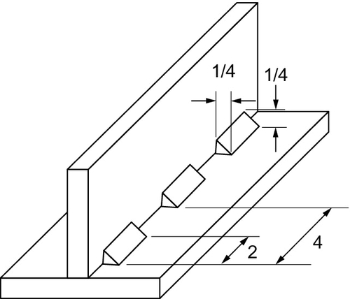
Figure 7.13Typical Intermittent Fillet Weld [5]
In many applications, a continuous weld is required in such places as where the joint needs to be water or gas-tight. It is the designer’s prerogative to select appropriate welds for appropriate conditions, but designers should be mindful of the cost and environmental implications of applying welds.
To simplify fabrication time, effort, and complication, it is useful to break down the costs and energy input associated with a normal welding process. Barckhoff, Kerluke, and Lynn [8] suggested that labor was the major cost of welding at 85% of the total cost. The pie chart in Figure 7.14 shows the percentage costs of the major elements of a welding application.
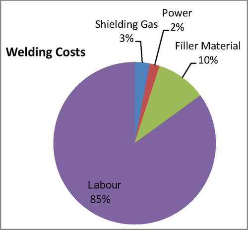
Figure 7.14Percentage Costs of the Major Elements of a Welding Application [5]
We can see that power consumption is only 2% of the cost, but it should be noted that power equates to embedded energy, and any reduction in power will lead to a reduction in the embedded energy within a fabrication. It is also true that labor contributes 85% toward the cost of the welding process. The application of labor equates to time spent, and a reduction here would give a large cost saving and, by implication, a saving in power applied.
It is often the case that fabrications are over-welded. In practice this relates to the human condition mentioned previously where a specified 5 mm throat weld in practice will receive a 7 mm throat weld, “just to be safe.” The application of a weld that is too large for its duty means that unnecessary time, unnecessary energy, and unnecessary materials have been expended. From a sustainability point of view, this is wasted energy and effort and increases the embodied energy within the fabrication.
7.6.6 Reevaluation of welds
In an exercise in reducing costs on a mobile plant chassis with a mass of 2 tonnes, a designer reevaluated the strengths of the chassis but also of the welds.
Welding costs can vary enormously with the thickness of material, the size of welding rod, and the power required. For this example, the chassis was fabricated from a 100 × 80 mm rectangular hollow section. Calculations are based on the mass of the deposition rate and the total mass of the welding rod deposited. The example uses a medium-duty weld type with medium power.
The objective of the exercise is to reduce the amount of welding within the chassis. The chassis comprises a rectangular hollow section with corners strengthened by webs. The average throat thickness (weld size) has been set at 6 mm. The values are based on a medium electrode size and the mass of electrode deposited during the welding process.
The chassis set out in Figure 7.15 indicates the welded joints, which were dimensioned at 6 mm throat in the original chassis. Figure 7.16 shows the throat dimensions of a typical fillet weld.
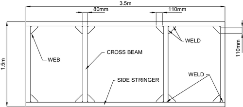
Figure 7.15Item of Plant Chassis Showing Welded Joints [5]
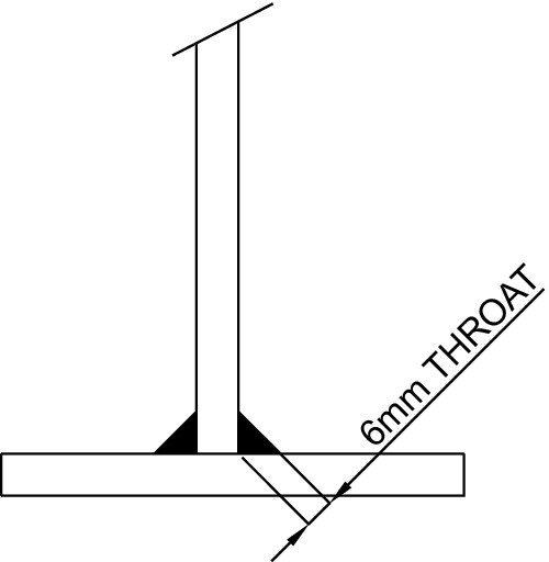
Figure 7.16Throat Dimensions of a Typical Fillet Weld [5]
Determine the mass of the deposition in the welded joints of the original chassis. These are as follows:
Main chassis welded joints:
Mass = 0.814 kg
Fillet weld joints for the web:
Mass = 1.49 kg
Total mass of weld in the original fabrication: 2.03 kg = 5.82 lbs
New chassis weld details:
New weld regime:
• Reduce the general weld throat to 3 mm
• Use continuous welds in fabricating the rectangular hollow section
• Use intermittent welds: 50/50; say, 25 mm weld/25 mm gap
Main chassis new welded joints:
Find mass of welds:
Mass = 0.2 kg
New fillet weld joints for the web:
Mass = 0.187 kg
Total mass of weld in the new fabrication: 0.387 kg = 0.85 lbs
The charts in Figures 7.17 and 7.18 give estimates of the time taken to lay down a mass of weld and an indication of cost implications.
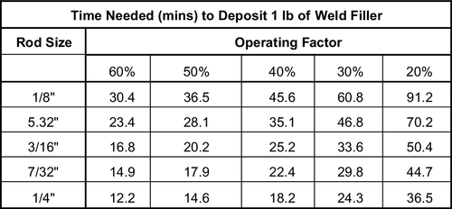
Figure 7.17Time Taken to Deposit One Pound of Weld Metal [9]
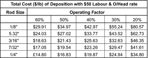
Figure 7.18Approximate Cost Estimation Pound of Weld Metal Deposited [9]
Original fabrication times and costs:
Using 1/8” welding rod diameter
Using 40% operating factor
Time taken:
Time = 265.4 mins = 4.42 hrs
Total cost:
Cost = $247.76
New Fabrication Times and Costs
Time taken:
Time = 38.76 mins = 0.65 hrs
Total cost:
Cost = $36.18
Percentage reductions:
Time reduction = 85.4% reduction in time
Cost reduction = 85.4% reduction in cost
7.6.7 Assembly methods: conclusion
Fabrication using various methods of welding is an extremely important and well-used assembly process. This exercise shows how a little thought by the designer in specifying welds could lead to an enormous saving, both in terms of cost and, more important from a sustainability point of view, power consumed. It highlights the fact that cost savings and sustainability improvement are symbiotic. An improvement in the area of cost often leads to a reduction in energy input.
The efficiencies have been based on costs, but it is reasonable to conclude that a reduction in time spent welding is, of course, a reduction in time spent applying power. The new fabrication with the improved welding regime will benefit from a much lower embodied energy value.
7.6.8 Fastening systems
In any assembly process, components need to be fastened together. The natural fastener for any designer to use is the humble screw fastening. These components, however, can prove difficult to feed, may jam, and require monitoring for presence and tightening torque. Fasteners often need expensive feeders, extra labor, and extra assembly stations. Corbett and Dooner [4] estimate that the driving of screws can be 6 to 10 times more costly than the fasteners themselves. A little thought by the designer as to how to fasten the components may eliminate screwed fasteners, perhaps instead using tabs or snap-fits.
It is inevitable that fasteners must be used in some circumstances. The following checklist highlights some elements of best-practice principles for selecting fasteners.
Fasteners in general:
• Reduce the quantity
• Use standard fasteners
• Use the same strength of fastener throughout the assembly
• Reduce the size of fastener
• Use one size of fastener
Receiving components:
• Avoid tapped holes.
• Employ captive washers and nuts, thus reducing the number of parts to assemble.
• Consider automated assembly requirements, e.g., the shape of screws required for vacuum pickup or using chamfered points for improved placement success.
7.6.9 Minimize assembly directions
All parts should be assembled from a single direction. If the main assembly has different access points, the whole assembly may have to be turned to allow access. This involves transfer stations and inspection stations and eventually leads to increased cost and energy input.
7.6.10 Maximize compliance
Components are not always identical. Misalignment, out-of-shape components, and component flexure are all problems that may reduce assembly efficiency. This was a major issue during the authors early days as an apprentice machie-tool fitter: covers rarely fitted the mating location on a casing. Major factors that can affect the mating parts include:
• Accuracy of component geometry
• Consistency of component geometry
• Stiffness of the component
• Stiffness of the assembly tool
• Rigidity of jigs and fixtures
• Friction between parts
To avoid assembly problems, compliance must be built into the assembly process. It is the designer’s responsibility to ensure that the preceding list of possible problems is avoided. Most can be circumvented through forethought; however, consistency of component geometry (accuracy of parts) may often be difficult to achieve, especially if parts are manufactured by an external source.
If automated assembly is being employed, compliance may be improved by the use of robot assembly systems employing elements such as tactile sensing, vision systems, quick change end effectors, and tools.
The designer can apply compliance features to the design, such as generous tapers or chamfers for easy insertion and other guidance features. An effective method is to use one of the major parts as a base unit. In the case of assembly of a passenger vehicle, it is conceivable that the car body would be the base unit to which all other parts can be fitted. This part base should be designed to be as stable and as rigid as possible, which will inevitably improve accurate insertion and simplify handling. This base unit may also be provided with accurate location points, generous tapers, and other features that can be used to guide insertion of additive components.
7.6.11 Minimize handling
Whenever components are moved to effect access or are moved from one location to another, costs and energy are involved. The greater number of times an assembly is moved, the greater the risk of:
• Damage to the assembly
• Slower cycle times
• Risk of diminished quality
• Increased complexity of equipment
• Increased cost of equipment
To minimize the handling and movement of assemblies, the designer should not only be aware of improved access but also should build in symmetry and orientation features that will guide and locate parts. Most products require some form of packaging, and it is with the assembly in mind that the designer could consider how the packaging should be applied. The packaging should be designed for easy handling and easy application and, when applied to the product, should also allow for easy handling and delivery. This can be achieved by understanding how the packaging could be fitted, including:
• Product flows within the facility
• Workspace facilities
• Packaging supply flow
For each element in this list, the designer should consider how the product, subassembly, or component can be designed to simplify flow to the packaging facility and away from it.
7.6.12 Design constraints and total design team formation
The designer must always perform tasks under several constraints. Costs may be considered the severest of the constraints and may consist of:
• Manufacturing costs
• Development costs
• Product support costs
• Warranty costs
Other constraints may be listed as follows:
• Timing and entry into the market
• Product technology
• Materials availability
• Manufacturing technology
• Volume, which dictates the method and rate of production; small batches would be treated very differently from mass production
• Ability to develop the product
• Projected life cycle
• Sustainability and environmental impact
This list is driven entirely on the type of product and has to be treated as a priority list from which elements may be added or subtracted to suit the design.
Traditional design methods complete the design process before manufacture has even been considered, but as the preceding list of considerations shows, an essential part of the design process is that of manufacturing method (among many other elements), which has to be built into the product at the design stage.
The design function can be polarized with a single designer working alone, perhaps as a consultant. His skills and knowledge would need to span design techniques, the product, the industry, and the manufacturing technique. As a consultant he would probably be commissioned by a company, in which case he would naturally look at the machine tools and processes available within the company so that he could familiarize himself with skills and techniques that are already in use. The aim here would be to reduce the costs by performing essential manufacturing in-house. To understand the intricate workings and systems of a particular company, the designer would need to liaise with key personnel and base designs on their advice and input.
At the other end of the polarized scale is a multidisciplinary design team that could proffer many specialist skills for the procurement, design, and manufacturing processes. Multidisciplinary teams offer an integrated and balanced approach and are an important factor in improving communications and the ability to consider many concepts simultaneously.
Corbett and Dooner [4] suggest that 70–80% of the production costs are defined at the design stage. The great advantage of multidisciplinary teams is that multiple aspects of the product can be considered simultaneously. Principal among these is the correct method of manufacturing. Specialist manufacturing staff, along with marketing staff, purchasing staff, and so on, work alongside the designers to assure product success by ensuring that the following elements apply:
• The product must work efficiently.
• The product can be manufactured efficiently.
• It is saleable.
• It is profitable.
• It has a low environmental impact.
It is the designer’s responsibility to ensure the total success of the product. Since 70–80% of the cost is also prescribed at the design stage, it can be seen that the designer has a huge responsibility, and it is suggested that the design function within a company requires total control in order to fully respond to this responsibility.
Some of the skills required within this multidisciplinary design team can be described by the particular tasks that are required, as described in the following discussion.
7.6.12.1 The value engineer
The value engineer considers the manufacturing process, associated costs, and material costs and traditionally sees the new design after it has left the design office. He may suggest modifications and improvements, but often these suggestions would prove too costly when manufacturing has already been implemented. It seems reasonable that the value engineer should be incorporated into the total design team during the design process.
7.6.12.2 Manufacturing engineer
The skills of a manufacturing engineer are very wide and varied. His role is to develop and create physical artifacts, but his knowledge must span production processes and the technology required to manipulate materials into a product. The manufacturing engineer will possess design, organizational, and communication skills, along with statistical and other mathematical skills. It seems appropriate that the manufacturing engineer should be one of the major contributors to the total design team.
7.6.12.3 Engineering purchaser
The engineering purchaser will need a fundamental knowledge of engineering, but her skills will lie in negotiating prices for commodities as well as understanding the fundamentals of the components required in the manufacture of a product. The role of the engineering purchaser within the total design team would be to advise on component costs, availability of products, the timing for procurement of components, and finally, the sustainability value of proposed components.
7.6.12.4 Product designer
The term product designer may have several meanings. The product designer’s role is to combine art, science, and technology to create new products. Within the total design team, it is the function of the product designer to create a product that is appealing and that will assist the marketing and sales function. Engineering designers and manufacturers may be able to create a product, but their skills are not normally in creating aesthetically pleasing articles. The product designer requires technical engineering skills, but her role is in applying aesthetic principles, along with her technical skills, in providing a product that is acceptable to the consumer. A food mixer, for example, may have the best technical specification on the market, but it would not be purchased and placed in people’s homes if it did not look good.
7.6.12.5 Marketing and sales
Through market surveys, the marketing function will provide the need and the brief for the design of a product. It is not normally commercially viable to design and develop a product when there is no market and no perceived need for it. The marketing department provides the market analysis that informs the development company that there is a need to be fulfilled. For example, the Apple iPad was a new introduction to the market. The Apple marketing team identified a market need. The foresight of Apple as a company developed the iPad into a very marketable product.
The sales function is often allied to the marketing function and is sometimes combined. The role of the salesperson used to integrate the product into the market during the development process, largely after the product had been produced.
Both marketing and sales personnel require technical insight, but this is not their primary function. However, they do need a place on the total design team to advise on several elements, including the accuracy of functions compared to market requirements, packaging, manufacturing quantities, and timing into the market.
7.7 Lifetime Usage
Lifetime usage relates to the environmental impact and hence the energy used and pollution created during the life of the product. For some products this element of the life cycle is the dominant feature of the whole embodied energy of the product.
7.7.1 Case study: item of plant: water-well rock drill
The water-well rock drill shown in Plate 7.7 comprises many different and diverse components, from steel fabrications such as chassis, fuel tanks, mast, and gearboxes through bought-in components such as diesel engines, compressor, wheels, and bearings. Clearly, the calculation of embodied energy in this product is complex, but using CES EduPack [3] software, we can analyze the major components and formulate an overview of the embodied energy applied at each stage of the whole life of the product.
Plate 7.7Water-Well Rock Drill [5]
For this particular exercise, it has been assumed that the whole rock drill has been manufactured through a fabrication process from low-carbon steel. This was the major manufacturing technique used in producing the rig. The rock drill was destined to be used in remote villages in the Himalayas and was transported via rail over 5,000 miles. The engine powering the rig was 800 hp and the rig life was assumed to be five years. It has been assumed that most of the components can be reused, refurbished, or recycled. The full breakdown of details is shown in the “Eco-Audit Report” in Section A7.3 of the Appendix.
The eco-summary for embodied energy is shown in Figure 7.19; the eco-summary for the carbon footprint appears in Figure 7.20.
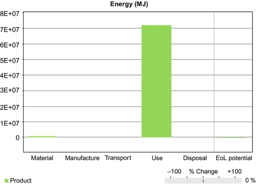
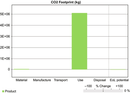
We can see that the carbon footprint and the embodied energy are very closely related. This is because it is assumed that all the energy applied to the rig in extracting materials, through manufacturing, use, and disposal, is also applied by fossil fuels, which can be termed artificial energy. The use of natural energy such as solar or wind power will inevitably reduce the carbon footprint, but it is unlikely to reduce the embodied energy value. If the drill rig is to function as normal, no matter what the energy source it will still need the same value of embodied energy. If natural energy is used, the rig function will become more sustainable and the carbon footprint will be reduced.
Both Figures 7.19 and 7.20 indicate that sourcing the materials, manufacturing, and transportation requires minimal energy, but this energy requirement is totally overshadowed by the energy used during the normal operation of the rig. If the designer is to reduce embodied energy in the life cycle of the drill, he has to carefully consider the energy needed to power it and how that energy is derived.
7.7.2 Case study: steel fabricated footbridge
The fabricated footbridge shown in Plate 7.8 requires a large element of energy during material sourcing and manufacturing. After installation, however, the footbridge is passive and requires no energy for it to function, apart from occasional maintenance. The life span was expected to be approximately 50 years. An eco-audit using CES EduPack [3] software determined the embodied energy value of the bridge. The results are shown in Figures 7.21 and 7.22, with a full detailed analysis in Section A7.4 of the Appendix. For the purpose of the exercise, the material was assumed to be virgin material that could only be reused or recycled at the end of its life. Furthermore, the deck was assumed to be timber from a certified source. This material was also to be reused at the end of the bridge’s life.
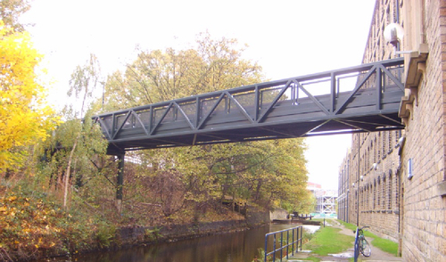
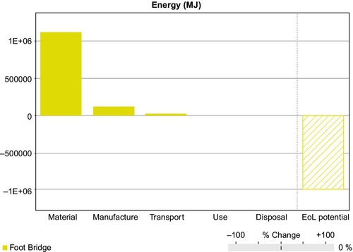
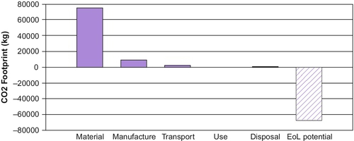
The footbridge requires no energy for it to function properly; therefore the embedded energy in its life of use is zero, which is quite a contrast to the rock drill in Plate 7.7. It is clear that the bigger part of the embodied energy, over 1 MJ, is used in obtaining the raw material, with approximately 100 kJ used in manufacturing. At the end of its life it was assumed that the steel and wooden components of the bridge would be reused or recycled, thus giving an enormous end-of-life potential of 1 MJ. This almost completely negates the energy used in sourcing material.
We previously stated that true sustainability is almost impossible to achieve. The data displayed in Section A8.4 of the Appendix suggests that there will be a 94% end-of-life potential for the bridge’s steel components due to the reuse of the material. The end-of-life component of the timber is only 6.5%, but this seemingly low figure is misleading, since the timber originated from a sustainable source, so the end-of-life potential will be much less. However, this is a figure that should be a major goal. There will always be losses in the system, but this bridge offers a glimpse of the sustainable efficiency that could be achieved.
The CES EduPack [3] software gives designers the opportunity to quantify products’ environmental impacts in terms of energy expended and carbon footprint. This software is an essential tool for designers and design teams who are attempting to reduce products’ embodied energy.
7.7.3 Designer’s duty
The duties of the designer or the design team are many and varied, but most consider that the primary objectives of any design are to:
• Reduce the cost
• Reduce the embedded energy
Cost reduction has been a primary exercise for designers since the design function came into being. The duty of evaluating embedded energy reduction is a more recent feature of the role and should be explored a little further.
The embedded energy within a product can be manipulated and reduced by concentrating on those areas that are shown to be the biggest contributors. In the case of the rock drill, the biggest contributor to the embodied energy is during its useful life, where the greatest environmental impact is derived directly from the use of the diesel engine from which it gleans its power. The designer must naturally concentrate on this element of the product’s life in order to reduce the power use. The reduction in value may be a tall order, since the drill still has to function, but the critical point here is to reduce artificial energy (energy derived from diesel engine) to natural energy or energy derived from natural sources such as wind or solar power, thus employing a sustainable power source.
The bridge’s embodied energy comes from the sourcing of the virgin material. The designer’s attention should therefore be drawn to sourcing the material, since this will repay the design in reduced embodied energy and can be achieved by using more recycled or reused materials.
As designers embrace sustainable engineering concepts, they not only assist many environmental conservancy issues, but they also reduce the costs of the product to the manufacturer.
7.8 Maintenance
In designing a product such as a motorcycle, the designer needs to consider the following points:
• Life of product
• Life prediction of components and design for scheduled component replacement
• Simplicity of components and standardization
• Accessibility for ease of removal of components
• Downtime: Dual components (redundancy) for continuous working while maintenance is being carried out
• Detail design for easy removal and component replacement, easy access, easy removal of fasteners, e.g., cap head screw, M 12 hexagon heads external use: easy fitting, bearings, seals
• Maintenance location: In the field, at the factory
• Modular build
• Lubrication and lubricant delivery
The approach to maintenance presupposes that there will inevitably be components that wear and need to be replaced. Any engineer can appreciate that some parts will wear more quickly than others simply because there is a part of the system that is more highly used. Bearings and seals fall into this category and can be regularly replaced.
7.8.1 Life of the product
The design life of a product relates to the period of time expected by the designers to function normally. The life of the product depends entirely on the product and its intended use. A short design life could relate to a disposable camera, which fulfills its useful life once its roll of film has been exposed. It should be noted that once the camera’s film has been extracted and converted into photographs, the casing is reused, repackaged, and marketed once again.
A longer design life could be attributed to a digital camera, which is more expensive than the disposable camera and which would be expected have a design life measured in years or even decades. Design life is often related to obsolescence but is distinct from that particular concept. Many products are still very useful and work perfectly to their original design parameters after a number of years but may become obsolete in the eyes of the user simply because they do not possess the latest technological advances.
7.8.2 Component life prediction
Whenever a design is created, the designer must have in mind the lifespan of the product, or at least the life expectancy of some of its components. The designer must also appreciate that the failure of some components, when in use, may lead to fatal consequences. The bearings carrying the rotors for a jet engine, for example, need a high level of reliability, since their failure in flight could lead to an aircraft crash.
It is a useful concept to design components into a product so that their lifespans can be predicted. This is often achieved by calculating the number of cycles and replacing the component when its end of life is predictably close. One such component is the humble rolling element bearing, normally rated with an L10 life. The life of rolling element bearings is defined as the number of revolutions at a given constant speed and load that the bearing is capable of enduring before the first sign of fatigue occurs in one of its rolling elements. It should be noted that fatigue is not the only mode of failure of a bearing. The L10 life value relates to the expected survival of 90% (10% failure) of the bearings under prescribed loads and speeds cycling for 1 million revolutions. Statistically, bearing companies expect a median life of approximately five times the calculated basic L10 life.
To put this into perspective, the designer can relate the load and speed applied to a bearing, enabling the calculation of the expected life through a number of cycles. A rule of thumb here suggests that half the maximum load will lead to roughly twice the length of life of the bearing. Armed with this information, the designer can predict the life expectancy of a particular bearing and suggest a period of use prior to essential maintenance. This is normal practice with passenger vehicles, which have particular maintenance periods for certain components. Typically these maintenance checks could include the following:
• Weekly checks: Minor elements, e.g., coolant level, tire pressure, engine oil level
• Six months: Renew engine oil and filter
• Twelve months: Drive belts, road wheels, brake calipers and discs, front suspension components, rear suspension components, drive shaft joint gaiters
• Two years: Renew brake and clutch fluid, renew coolant
• Four years: Renew spark plugs, renew timing belt, renew fuel filter
This list is indicative but shows that vehicle designers have considered the wear rate of various components and have suggested a maintenance program to the owner. Such a maintenance program would be absolutely essential for aircraft, since failure in the air could lead to a substantial number of fatalities.
7.8.3 Simplicity of components and standardization
Simple components are normally low-cost and require low energy to manufacture. They should also be easy to fit, especially if the design considered the location and fixing technique. This could be as simple as a hole in the receiving component and a spigot on the replacement component with a simple snap fitting. A simple vehicle headlight bulb is an excellent example. The replacement simply plugs into the headlamp socket, which normally then fits into the headlamp receiving hole from behind, requiring only a quarter turn to fix it in place. The unit is located and fixed in one simple movement.
Many standard components can be purchased from most engineering stockists. These components can be incorporated into the design and include bearings, seals, screws, rivets, nuts, pins—the list is endless. These components are very low-cost and readily available. It is normally good practice to replace bearings as well as seals, screws, washers, and the like whenever maintenance is carried out. When maintenance is done in the field, the maintenance engineer would probably carry with him a standard set of parts intended for the maintenance of a particular device.
Standardization may also apply to manufactured components within the product. A range of gearboxes may require spur gears in different combinations. Gears could be standardized to benefit from high-volume production, but careful design would reduce the number of different gears required to be kept in stock for replacement in the range of gearboxes.
7.8.4 Accessibility for ease of removal of components
During the design process the designer must consider the assembly procedure as well as the disassembly procedure of a device. It is poor practice to weld a plate in place when the bearing behind it requires removal during the next maintenance operation.
It is important that the device’s design gives appropriate physical access to accommodate tools, extraction devices, maintenance personnel, or at least the hands of maintenance personnel, with enough room to rotate wrenches, sockets, and screwdrivers. Components requiring regular replacement should be located to the outside of the product rather than buried internally and creating access difficulties, thus extending the time to maintain the device.
7.8.5 Downtime
The time it takes to maintain a component is critical, since often production will come to a halt. Companies plan scheduled shutdowns so that maintenance can take place on critical equipment. If equipment breaks down during a production cycle, millions could be forfeited in lost production when the fault could merely be a rolling element bearing that costs £20 (US$30).
Designers need to build in simplicity of maintenance so that speedy maintenance can be accommodated. Sometimes it is necessary for a critical unit to function while maintenance is being carried out. In such a case, redundancy is built in in the form of dual components. Here one set of components can perform the function adequately while the other is being replaced. A typical such application can be seen in the oil recirculation unit shown in Plate 7.9. Twin motor/pump units can be seen placed on top of the tank. This is typical of built-in redundancy where maintenance on one motor/pump unit can take place while the other motor/pump unit performs the normal function of the unit.
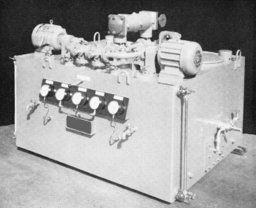
Plate 7.9Oil Recirculation Unit Showing Twin Motor Pump Units [13]
An unscheduled shutdown caused by a parts failure can be extremely expensive for a company. Scheduled maintenance is usually planned to avoid this issue, but more and more companies and factories are using modern technology to detect obscure vibrations and noise in things such as gearbox drive units so that they are forewarned of an impending failure and can plan for an ad hoc maintenance exercise on, say, a drive unit. This could be done between shift changeovers and may involve planning that a new gearbox be inserted while the failing gearbox is removed.
7.8.6 Detail design for quick-and-easy maintenance
The detail designer, when providing a product’s manufacturing drawings, needs to consider easy access for tools and extractors. For instance, a shoulder may be provided for a bearing to be located against, but the detail designer will need to increase the diameter of the shoulder to give access for a drift to be inserted to knock out the bearing, as shown in Figure 7.23. Here there is ample access for the drift to purchase on the outer and inner race of the bearing so that it can be knocked out of the housing. The same method needs to be applied to other replaceable components such as seals.
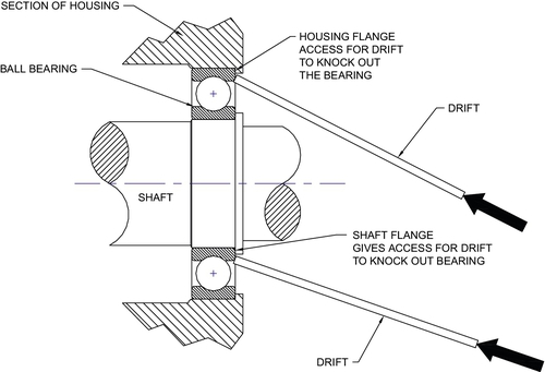
Figure 7.23Provision for Removal of Bearings from a Bearing Housing and Shaft [5]
Consideration also needs to be given to removal of screws. Designers will specify which screws and where they should be applied, but a golden rule is to apply screws so that they can be easily removed. This often depends on the end use of the product and the environment in which it will be used. If the device is an item of plant used outside in the open, it would seem ridiculous to insert small cross-head screws. These screws will easily rust and be impossible to remove. Similarly, cap-head screws sporting an Allen socket hole in the head will easily fill with debris if used in outside environment. This will make it difficult to insert the Allen key. These screws are also high tensile and have been heat-treated. They are usually supplied covered in oil film but will easily rust when exposed to weather. These screws are clearly intended for internal use on such devices as machine tools.
Good practice for items of plant used outside and subject to normal weather conditions is to apply a minimum of M12 (1/2” UNC) hexagon headed screws (bolts). The hexagon head can easily be cleaned of debris with a wire brush and will give enough purchase for a socket or a ring spanner, thus allowing the maintenance personnel to easily remove the screws.
These are just a few of the elements an experienced designer must consider for the maintenance process when providing detailed drawings prior to manufacture of the components.
7.8.7 Maintenance location
The location of the normal maintenance practice has an enormous effect on the design and selection of components. If the maintenance can be done in comfortable surroundings of a workshop where there are available tools, cleanliness can be observed, and temperatures are reasonable for maintenance personnel, then the maintenance practice is fairly straightforward. Consideration can therefore be given to more standard components that can be removed, perhaps with a bench press or with available power tools. Maintenance in the field is quite a different matter.
Maintenance in the field could mean on the factory floor, where production is taking place, or it could mean that the maintenance personnel have to travel to the machine, which could be in a quarry or in a mountainous region hundreds of miles from the nearest workshop. If maintenance is to be done in situ on the factory floor, then access to power tools may be limited and, depending on the process, might prove dirty and uncomfortable for the maintenance personnel. A dirty environment is also the enemy of clean assembly. Should dirt ingress the assembly, premature wear could take place. It is particularly important for hydraulic assembly to take place in a clean environment, since small dirt particles (smaller than the naked eye can see) could infiltrate the very close-fitting components in, say, hydraulic pumps and cause premature wear and premature failure. In such cases, design elements and good practice, as discussed, should be built into the design to promote quick, easy, and clean maintenance, thus reducing downtime and easing the load of the maintenance fitter.
In extreme cases, items of plant may be used in a very hostile environment located many, many miles from the nearest service depot. In such cases, service engineers need to travel to the device that requires maintenance. An excellent example of such a case is explained in the following case study.
7.8.8 Case study: water-well rock drill
A water-well rock drill was designed to operate independently in the bush in Africa. The specification for the rock drill was to drill 100 mm diameter (4”) holes, approximately 400 m (1,200 feet) deep, to access the water table. When the hole had been drilled, a down-the-whole water pump could be inserted to bring water to the surface. This would then be the water supply for local villagers.
The drill was based on a trailer and towed by a long wheelbase Land Rover. The whole rig was designed for maintenance in the field and independent use. This included the application of maintenance procedures in the field. One particular component on the rig that had the most arduous use was the rotation gearbox, which is highlighted in the schematic of the drill rig in Figure 7.24.
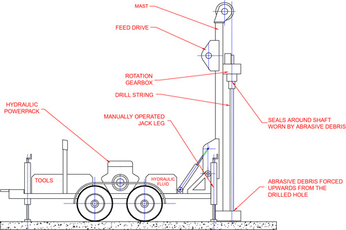
Figure 7.24Trailer-Mounted Water-Well Rock Drill Used in Remote Areas [5]
The rotation gearbox rotates the drill string and supports several tonnes of drill pipe. Compressed air is passed down the drill pipe to operate a hammer bit at the bottom of the hole. The remaining energy within the compressed air brings highly abrasive dust to the surface, hitting the underside of the gearbox. Seals in this location operate under extreme wear conditions. The seal retains the oil in the gearbox and prevents ingress of the abrasive debris. Inevitably oil escapes through the seal and forms a paste with the abrasive debris, which tends to wear a substantial groove in the shaft under the seal. Under normal circumstances the shaft would be removed from the gearbox and sent to a workshop, where the seal/shaft contact surface would be renewed by a deposition process and machined to accept the seal once again. The shaft could then be replaced in the gearbox.
This process is impossible when the rig is operating over 600 miles from the nearest factory. During the design process, a solution had to be found for the wear problem or risk weeks of downtime and lost production in the field. The solution was to use a “cassette seal,” a cross-section of which is shown in Figure 7.25.
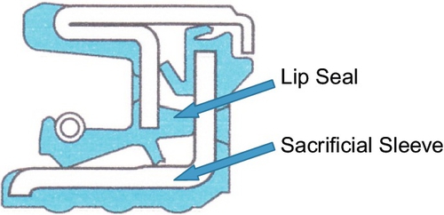
Figure 7.25Example of Cassette Seal Showing Sacrificial Sleeve [11]
The seal provides a sacrificial sleeve on which the lip seal rides. The sacrificial sleeve is a tight fit on the shaft forming a static seal with the shaft. This means that the sacrificial sleeve wears rather than the shaft. Maintenance is now possible in the field, since an extractor can remove the sacrificial sleeve and a new cassette seal can be applied to the shaft. The shaft does not suffer any wear at all and does not have to be returned to the factory. Downtime in the field is now measured in hours rather than weeks.
The service engineers suggested that gearbox lid gaskets often get damaged in transit. A solution was found in PTFE cord. This is pure PTFE and can be purchased from seal providers in diameters of 3 mm, 6 mm, and up to 15 mm. Rather than a gasket, the designer specified 3 mm diameter PTFE cord, which could then be applied to the interface between the gearbox lid and the gearbox case, providing a perfect seal when the gearbox lid was fitted. The problems of protecting gaskets in transit did not exist with a length of PTFE cord, since it could be transported in a roll. This feature also promoted maintenance in the field and was applied at the design stage.
7.8.9 Modular build
The advantages of modular build were dealt with earlier in this chapter. From a maintenance point of view, the replacement of a module is quick and easy. If the module has stopped functioning, it could be replaced by a working module and removed back to a workshop where appropriate facilities and maintenance time can be allocated. Perhaps the biggest advantage of using modules is that downtime is minimized on the main product.
7.8.10 Lubrication and lubricant delivery
Lubrication is often the last thing considered in any design, but it should be treated like any other major component. Most lubricants after all can be considered liquid engineering.
A lubricant is a device introduced between two components that slide relative to each other. The task of the lubricant is to prevent the two components from coming into contact and therefore abrading each other. Dry steel rubbing on dry steel will tend to “pick up.” This means that material from one component will be deposited on the other component, and vice versa. It does not take long before both surfaces become rough and unusable. This can be demonstrated by rubbing together two glass bottles. Both will appear burned and both will “pick up.” When lubricant is introduced between the two adjacent surfaces, the lubricant film will shear, effectively allowing the surfaces to ride on the sacrificial film. The end result is that they will slide relative to each other without touching and without wear.
Lubricants are available in many forms, from hard, highly viscous lubricants that are the consistency of frozen butter to lubricants with a low viscosity, an example of which is paraffin. Lubricants are normally considered oils, but these, along with greases, are the more common types. More specialist lubricants could be any material that can be inserted between the two sliding components. Graphite is among these, as are copper and other specialist materials, including engineering plastics, though the use of these tends toward “self-lubricating bearings” rather than pure lubrication.
Perhaps the most obscure “lubricant” is that of lignum vitea. This slow-growing timber of the genus Guaiacum has been used for centuries as a self-lubricating bearing, especially in underwater applications. The timber is the only wood that will sink in water due to its extreme density, caused by the saturation of lignum (tree sap). The classic use of the timber is between a ship’s hull and the slipway prior to launch. This use is in the true sense of a lubricant in that it is a sacrificial element between two sliding surfaces.
Oil can be used in various applications and can vary in viscosity. Oils can be “designed” for a particular application and may have additives such as antifoaming agents for high-shear applications such as in gearboxes. Oils can also be designed for high-pressure applications for such components as vehicle differential gearboxes.
Greases are effectively oils that are mixed with soap. The soap, perhaps silicon soap or lithium soap, is a carrying agent that acts like a sponge, absorbing the lubricating oil. Greases can be regarded as plastic solids and differ from normal oils in that they will not flow unless subjected to shear stress. Also when subjected to shear stresses, greases become increasingly mobile, that is, they become more liquid. A very useful property of a grease is that it will stick to the component, whereas oil needs to be contained and physically kept in contact with the component.
In designing a component with moving parts, the designer needs to consider not only the type of lubricant but also the delivery system. Moving components will require a lubrication system and a lubricant designed for that system only. An internal combustion engine requires an engine oil of a particular viscosity, where the oil is contained in the sump and pumped to vital components in the engine and gearbox. The gearbox bearings and gears in the rotation gearbox in Figure 7.24 are lubricated by being partially submerged in an oil bath. Grease lubrication is useful for standalone bearings such as those used on the rolls of a paper mill. A plumber block (sometimes called a pillow block) bearing, shown in Plate 7.10, is usually packed with grease simply because grease is sticky enough to stay inside the bearing. Note the grease nipple on the top of the housing, through which grease can be injected via a grease gun or other grease pressurization device.
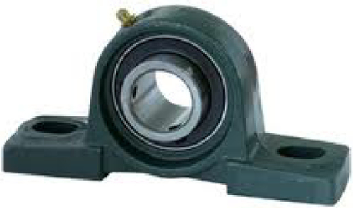
Plate 7.10Typical Plumber (Pillow) Block Bearing [12]
Fast-moving components tend to discard the lubricant by flinging it away. Such is the case with motorcycle chains. Specialist lubricants have therefore been developed for these kinds of situations. The lubricant needs to be sticky enough to coat the moving parts without being flung away, but in the case of a motorcycle chain, it should also avoid picking up dirt and debris. These conflicting requirements can be met by combining the oil with various additives.
7.8.11 Lubricant delivery systems
Delivery of lubricants depends on the lubricant and the object being lubricated. Perhaps the simplest method of injecting (usually) grease into a bearing is via a grease gun. A selection of grease guns is shown in Figure 7.26.
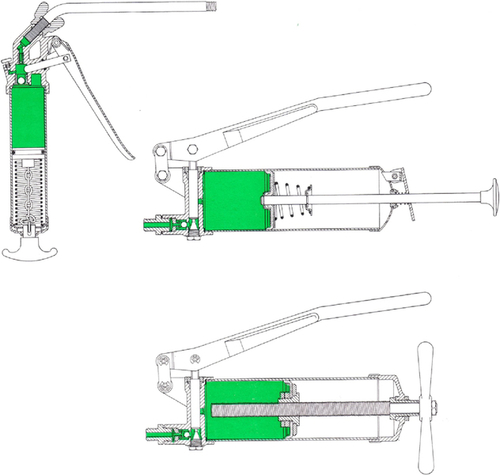
Figure 7.26Selection of Typical Grease Guns [13]
Grease guns deliver grease through a grease nipple at high pressure up to 50 bar, forcing grease into a bearing. Bearings can take several forms and can be used in many varied situations. Plumber blocks are shown in Plate 7.10, but there are many other styles and types, such as rod ends on hydraulic rams or, indeed, in any situation where there is individual metal-to-metal contact.
There is an element of guesswork in dumping grease into bearings, since quantity cannot be measured and there is uncertainty in some cases with the grease reaching the bearing. When more certainty is required, we can use automatic lubrication systems, which feed measured quantities of grease or oil through connecting pipes directly into bearings. A typical dual-line-injection measurement valve system is shown in Figure 7.27.
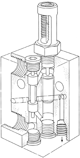
Figure 7.27A Dual-Line-Injection Measurement Valve [13]
This type of valve is equipped with an indicator that can sound alarms if there is a blockage in the line. These valves are placed in blocks of up to 12 valves. The outlets from each valve are then piped directly to the bearings through smaller-bore pipes. Pipe fittings carrying the small-bore pipe then replace grease nipples. A typical dual-line lubrication system application is shown in Plate 7.11, where there are several dual-line-injection valves piped directly to bearings.
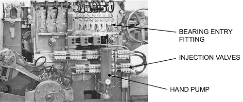
Plate 7.11A Typical Dual-Line Lubrication System Application [13]
This typical dual-line lubrication system is fitted to a mobile machine and is therefore fed by a hand pump. Pressurized grease is forced through the injection valves, which in turn feed the pressurized grease through smaller-bore pipes directly to the bearings through pipe fittings.
In stationary applications—for instance, in rolling mills—there may be a specific room set aside for the pumping systems. A typical pump room is shown in Plate 7.12. Several grease reservoirs can be seen. Beneath the reservoir is the pumping system, driven by electric motors. Typically these pump units will feed high-pressure grease or oil to a dual-line injection system such as that shown in Plate 7.11.
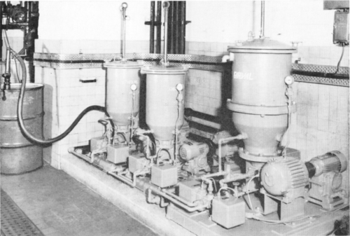
Plate 7.12A Typical Lubrication Pump Room [13]
7.8.12 Engineering plastics
Engineering plastics have become revolutionary new bearing materials that, under some conditions, have many more benefits than standard bearing systems.
Engineering plastics are group of plastic materials that exhibit superior mechanical and thermal properties in a wide range of environmental conditions. These materials can be manufactured to suit a particular application and are excellent when encountering conditions in which rolling element bearings or other stationery bearings are unsuitable. Such conditions are listed here:
• Low speed
• High load
• Wet or submerged conditions
• Dry conditions
• Impossible-to-lubricate conditions
• Oscillating shafts
• Linear bearings
• High-wear situations
• Self-lubricating situations
Engineering plastics can be manufactured to be porous and thus be impregnated with extra lubricant. The basic materials listed here can also be mixed with strengtheners such as fiberglass, Kevlar, carbon fiber, or the like. During the manufacturing process, engineering plastics may also have included chemicals and other additives that improve properties such as brass particles, which enhance the high-temperature performance.
Engineering plastics are based on several popular plastics such as polyethylene, nylon, PTFE, ABS, polyamides, and many more. Specialist companies are very willing to give advice on particular applications.
Engineering plastics can be found almost everywhere, but for the layman the most obvious place to find these plastics is in the passenger vehicle. Engineering plastics are used extensively in fenders, facia, steering wheels, engine manifolds, and rocker box covers. There are many other applications, such as food pumps, skateboards, motorcycle crash helmets, coffee pots, kitchen knife handles, and toolboxes.
Plastic bearings offer the opportunity of almost zero maintenance. In many instances they can be considered a “fit and forget” bearing. The drive shaft for the bed-lifting device in Figure 7.4 rotates in plastic bearings. These units are placed in domestic bedrooms and therefore cannot be regularly maintained. Plastic bearings are an ideal choice and are expected to last longer than the life of the drive unit. When drive units are thus replaced, bearings will also be replaced.
Let’s look again at the water-well rock drill in Figure 7.24, which uses linear (flat) engineering plastic bearings on the slides, thus enabling the rotation gearbox to slide up and down the mast. Furthermore, the drill string requires guidance before entering the ground. The engineering plastic guide bush at the base of the mast guides the drill string. Both the linear bearings and the guide bush operate in an extremely harsh and abrasive environment. Practice shows that debris tends to embed itself in the plastic and polishes the metal on which it slides. It would be difficult to find other bearing materials that could fulfill the same function so efficiently.
Plastic bearings are also used on the pintle bearings of ships’ rudders. When ships are loaded with cargo, the pintle bearings are submerged. When the cargo ships are empty and riding high in the water, the upper bearing is often dry. Engineering plastic bearings cope with this situation extremely well.
7.9 End-of-Life Disposal
End-of-life disposal was covered at length from a practical point of view in Chapter 3. It is now necessary to revisit the methods by which a product can be sustainably disposed of from the designer’s point of view.
Every product eventually comes to the end of its life. This may be due to a number of factors:
• Overtaken by technology
• Reduced popularity in the market
• Worn but still functions
• Worn beyond usefulness
• Functioning at less than full capacity
• Broken, beyond repair
When a product suffers any of these fates, it may be deemed that it is at the end of its life. It is the role of the designer to recognize these modes of failure and design into the product easy, low-cost, and low-energy methods of disposal. Sustainable thinking at the design stage will greatly reduce the embedded energy and cost in the disposal process.
The general approach to end-of-life disposal is the familiar 4R approach:
• Reduce
• Reuse
• Refurbish
• Recycle
These are almost universally accepted methods of disposal at the end of life of a product, but when they are cross-referenced to the end-of-life failure modes, the designer may see some clarity in design approach methods. A table cross-referencing failure modes to end-of-life disposal methods is shown in Figure 7.28.
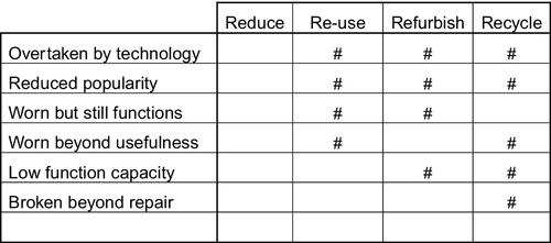
Figure 7.28Failure Modes and Disposal Methods [5]
7.9.1 Reduce
It is immediately obvious that the term reduce does not seem to have any significance. In the context of end-of-life solutions, reduce merely means to consign as little as possible to landfill. It also means that the remaining three options of reuse, refurbish, and recycle should be applied as much as possible so that in theory, 100% of a product is reapplied in some way, with nothing being just “thrown away.” This may be an idealistic number, but through proper design the end of life of a product may come close. Vehicle designers and manufacturers, for instance, aim for 95% of their product being reapplied in some way.
The application of the idea of reducing can be more usefully employed during the design stage by reducing mass. If the product requires energy for it to be moved, a reduction in mass would require less energy, which would have a great impact on the sustainable use value (SUV). For example, in the United Kingdom, fuel stations are a maximum of 25 miles (42 km) apart, yet most vehicles have a range of 300 to 400 miles (500 to 666 km) on a tank of fuel. It seems reasonable to reduce the size of fuel tanks so that fuel will not be carried unnecessarily.
Reduction at the design stage also means “do not overdesign.” Overdesign generally means more weight, more parts, and more energy required to process the material into a component. Careful analytical work can be employed here so that the only material applied to a product is that which is needed. The designer may also be tempted to reduce the design to such an extent that it loses its market personality. A computer would still function with all the components arrayed on an appropriate base, but it would not sell in the marketplace because the market would expect it to have an aesthetic casing.
The golden rule, therefore, is to reduce the design to what it needs to function as a product, but it may need much more than just mere function, in which case all the needs of the product must be considered, including those required to entice the market.
7.9.2 Reuse/Refurbish
The reuse of articles most appropriately applies to products that are still functioning but for many reasons might not be useful. Some products may be overtaken by technology, where advances have made the product obsolete. There are several excellent examples, described here.
In the early 20th century, sheet music was replaced by vinyl singles and long-playing (LP) records. These were subsequently replaced by eight-track and then cassette tapes, and as technology advanced, these were overtaken by compact discs (CDs). The CD format was in turn replaced by Internet downloads and digital music. Significantly, the pace of technological change has increased almost exponentially.
Photographic technology developed in the latter portion of the 19th century using glass plates and silver halide as a light-sensitive material. In the early part of the 20th century, the glass was replaced by celluloid film. In the second half of the 20th century, photographic slides were used and viewed with a slide projector similar to the Aldis projector shown in Plate 7.13.
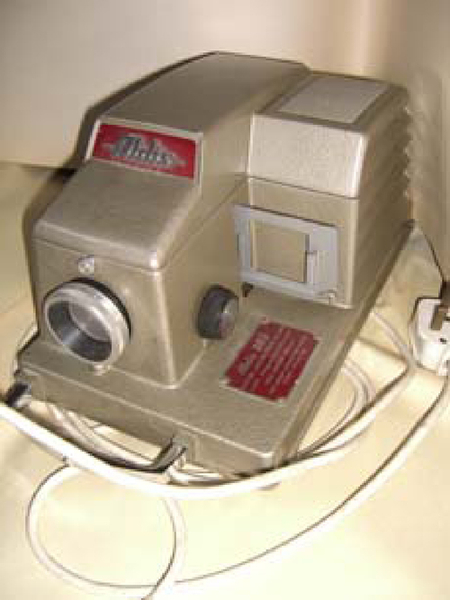
Plate 7.13Slide Projector, Circa 1955 [5]
In a short space of time since then, digital technology has made obsolete celluloid film cameras and their viewing equipment. Digital technology is also changing the way photographs are taken. Today almost every mobile phone is equipped with an excellent camera. Photographs can be converted into files and shared via the Internet or merely through the mobile phone service.
The dilemma for today’s designers is that of understanding where technology will advance so that they can build into their designs an element of “future proofing.” To some extent, this has been done with computing equipment and software, for which the technological advances have improved at an exceedingly fast pace. Some computer manufacturers have kept pace by offering modular construction, in particular toB2B clients that have skilled IT professionals to specify and upgrade units in-house using new modules. The challenge is now to change the habits of B2C customers, who tend to be more fashion driven and will often discard units well before the end of their useful working life.
During the design of new products, the designer should be aware that this product may come to the end of its life before its useful life has ended. Design for dismantling should therefore be a feature of the design process, enabling not only maintenance but also end-of-life disposal. Dismantled parts may be reused, refurbished, or, as a last resort, eventually recycled.
Industrial products do not suffer so much from market fickleness. Industry relies on equipment functioning efficiently, but as the equipment becomes worn and less efficient, companies normally prefer to refurbish rather than replace, since replacement is more costly than refurbishment. A piece of refurbished industrial equipment can be returned to full use and 100% efficiency for a fraction of the cost of a new device.
When a piece of equipment is worn beyond usefulness or repair, the only option is to either reuse useful components or recycle the individual components. Within this scenario could be included vehicles that have crashed and are beyond repair or industrial components that have been left in the environment to rust and therefore cannot be usefully repaired.
7.9.3 Recycle
Eventually all components and products will end their useful lives and suffer dismantling and disposal. Designers’ aim is to provide the wherewithal to separate and recycle all the different components and materials that originally made up the product.
Inevitably, components that are to be reused or recycled need to be separated into their unique materials. As materials are sorted for recycling purposes, the most difficult process is that of defining individual materials.
For example, glass cullet ready for remelting is often made up of multiple glass colors such as green, brown, blue, and clear. There are uses for colored glass, but often reused glass needs to be pure and clear. Glass recycling agencies run into difficulty in separating colors.
Furthermore, there are multiple types of plastic, such as polypropylene, polyethylene acrylic, polycarbonate, and polyurethane. Recyclers encounter great difficulty in separating the different plastics when they all look very similar and there is no usable detection method.
7.9.4 The designer’s role
During the process of design for manufacturing, including ease of assembly, it is often the case that the same techniques can be used to disassemble a product that were used to assemble it. However, elements such as snap fasteners and adhesives can slow disassembly. As the design progresses through the concept into the detail design stage, the designer may consider dismantling techniques alongside the more standard assembly methods. Since the separation of materials is one of the most difficult tasks, distinct joints should be made in the product between different materials so that it becomes easy to separate the various components at those joints.
The process of separating individual materials is not likely to be careful dismemberment of the product, as one might expect with an assembly process. It is most likely that powered machines will roughly separate components. Joints should therefore be designed into the product that will function properly when the product is in use but that will easily separate under the right conditions at disassembly.
7.9.5 Case study: reuse of floor panels
Floor panels of 600 × 600 × 40 mm thick are manufactured from fiberboard encased in a thin galvanized steel skin. The floor panels are used for suspended flooring and are often faced in carpet or plywood, such as maple, then varnished. The refurbishment process involves separating the 10-mm-thick plywood from the floor panel, but the adhesive used between the floor panel and the plywood was a thermo-set and could not be melted or reduced by a solvent. The separation process involved designing and building a hydraulically driven knife blade that separated the plywood from the floor panel. A great deal of cost and energy were applied in developing and using the machine tool that separated the two materials. If at the floor-panel design stage thought had been applied as to the end of life dismantling method, many different adhesives could have been specified that would have been easier to separate.
It can be increasingly seen that the designer or design team has an enormous task in order to design a product that meets market requirements and considers the requirements of sustainability. Though many engineers consider sustainability an additional burden, it is clear that to reduce costs, many sustainability principles are already being applied. Some elements of the sustainable design process are perhaps not as obvious as others. One of these elements is designing for disposal. An easy disposal process designed into the component or product will return a low embedded energy, especially when components are recycled into raw, usable materials. It is therefore the designers’ remit to reduce the embedded energy and return an improved sustainable disposal value (SDV).
References
[1] McLamb E. Ecology Global Network. 2011. www.ecology.com.
[2] Alternative Energy Group, 2012. www.altenergy.com.
[3] Granta Design CES EduPack, Granta Design Ltd.: Rustat House, 62 Clifton Road, Cambridge, CB1 7EG, United Kingdom.
[4] Corbett, Dooner, Meleka, Pym, Design for Manufacture, Addison-Wesley, Pearson Education, Harlow UK, 1991.
[6] S. Lampkin, U.S. Air Force, 2012. www.defenseimagery.mil. (This image or file is a work of a U.S. Air Force Airman or employee, taken or made during the course of the person’s official duties. As a work of the U.S. federal government, the image or file is in the public domain.).
[7] T.B. Christiensen, Modularized Eco-Innovation in the Auto Industry, J. Clean. Prod. 19 212–220.
[8] Barckhoff JR, Kerluke KM, Lynn DL. Certified Welding Supervisor Manual for Quality and Productivity Improvement. Miami: American Welding Society; 2005.
[9] R. Geisler III., Specials Certification Engineer and AWS Certified Welding Inspector, [email protected], The Lincoln Electric Company: www.lincolnelectric.com.
[10] Brown Europe Ltd: Gleaming Wood Drive, Unit 33-34, Lordswood, Chatham, Kent, ME5 8RZ, United Kingdom; [email protected].
[11] Freudenberg Simrit GmbH & Co. KG, D-69465 Weinheim, Germany.
[12] SZR Bearing Co.: szr-bearing.com.
[13] The Application of Lubricants, Shell International Petroleum Co., London, UK, 1965.
[14] Ashby MF. Materials Selection in Mechanical Design. Oxford: Elsevier; 1999.
Bibliography
[1] Dym CL, Little P. Engineering Design. Hoboken, NJ: John Wiley & Sons; 2009.
[2] Sheard R. The Stadium: Architecture for the New Global Culture. Hong Kong: Periplus Editions; 2005.
[3] Ashby MF. Materials Selection in Mechanical Design. Oxford: Elsevier; 1999.
Glossary
Embodied energy. Additive energy required to create a product. Depending on the processes used in its design and manufacture, this embodied energy will consist of elements of artificial energy and natural energy. Artificial energy embodies energy derived from such sources as diesel, petrol, and gas. Natural energy is derived from sources such as wind power, solar power, and wave power.
Artificial energy. Notionally, the energy derived from fossil fuels used in the creation of a product.
Natural energy. Notionally, the energy derived from natural means such as hydroelectric, wind, or solar used in the creation of a product.
Carbon footprint. The value of carbon emissions released during the conversion of energy from fossil fuels.
Depth of section. In beam theory, the depth of section is the distance between the upper surface of the beam and the lower surface of the beam. An increase in depth of section generally improves the load-carrying capacity of the beam.
Useful Addresses
FSC
Rainforest Alliance
259-269 Old Marylebone Road
London NW1 5RA, U.K.
Tel: + 44 (0)207 170 4130
U.K. Media Inquiries
Stuart Singleton-White
+ 44 (0)771 040 3092
Washington, D.C. Office
Rainforest Alliance
2101 L Street, NW
Suite 800
Washington, D.C. 20037 U.S.A.
Tel: (202) 903-0720