
Information Technology Systems Infrastructure
Abstract
Chapter 11 is one of the most important chapters in the book. The TCP/IP suite of protocols is the basis for information technology networked systems. TCP/IP operates on levels 3 and 4 of the OSI networking model. Data is encapsulated from the application program through the seven layers down to the network wire, sent across the network, and then decapsulated back up the seven layers to the application on the other end.
Chapter 11 covers the family of TCP/IP communications protocols related to security systems, including TCP, UDP, RTP and IP. TCP/IP protocols are described both as protocols and also as an addressing scheme. Chapter 11 also includes common wiring schemes including Ethernet and fiber-optic cables. Ethernet is available on Cat 5, Cat 5E, and Cat 6 cable at speeds of 10, 100, and 1000 Mbps or 10Base-T, 100Base-T, or 1000Base-T (gigabit Ethernet).
Chapter 11 also discusses edge devices including IP video cameras, IP intercoms, and codecs. Network infrastructure and wiring is connected using hubs, switches, routers, and firewalls.
Integrated security system network computers include servers and workstations. Printers and mass storage systems round out the network attached devices. Mass storage systems include network attached storage and storage area networks.
Typical video compression schemes include MJPEG, MPEG-2, MPEG-4 and H.264.
Workstation types include security monitoring centers, guard or lobby desk workstations, administrative workstations, photo ID workstations, and access verification workstations.
Multicast protocol is sometimes used in digital video systems, but it is fraught with many nuances requiring special skills and knowledge.
Chapter 11 completes with a discussion on archiving calculations.
Introduction
This may be one of the most important sections in the book. The designer who does not thoroughly understand TCP/IP is at a severe disadvantage in design, in construction management, and in system commissioning. The designer is at the mercy of installers and physics, both of which can harm him or her. Not understanding TCP/IP is like not being able to read or write. This is not a comprehensive tome on TCP/IP. I suggest that the reader buy several other books on the subject. This description is intended for the novice designer.
Basics of TCP/IP and Signal Communications
TCP/IP is the basic protocol of digital systems. From the understanding of that protocol all knowledge about digital systems flows.
How TCP/IP Works
The purpose of TCP/IP is to guide information from one place to another on a digital network. In the beginning, when computers were owned only by the government, military, universities, and really big business (banks and insurance companies), computers were not networked. Universities and the military held discussions on how to network their machines. The first network, called ARPANET, was developed in 1969 using Network Control Protocol, an early predecessor to TCP/IP. Although this permitted limited communications, several problems were evident, mainly that computers could only talk to other computers of the same manufacturer using the same operating system and software. This was not good because the whole idea was to allow communication, not to limit it. After several iterations, TCP/IP evolved. TCP/IP is really two separate protocols. TCP stands for Transport Control Protocol, and IP stands for Internet Protocol. TCP was developed in 1974 by Kahn and Cerf and was introduced in 1977 for cross-network connections. TCP was faster, easier to use, and less expensive to implement. It also ensured that lost packets would be recovered, providing quality of service to network communications. In 1978, IP was added to handle routing of messages in a more reliable fashion. TCP communications were encapsulated within IP packets to ensure that they were routed correctly. On the receiving end, the TCP packets were unpacked from their IP capsules. Experts quickly realized that TCP/IP could be used for virtually any communication medium, including wire, radio, fiber, laser, and other means. By 1983, ARPANET was totally converted to TCP/IP, and it became known as the Internet.
TCP/IP Operates on OSI Levels 3 (IP) and 4 (TCP)
One of the basic functions of networking involves the process of layering communications. Like making a sandwich, one cannot begin by spreading mayonnaise on one’s hand. You have to put it on bread. Then you add the meat, lettuce, pickles, and other ingredients, and finally a last layer of bread. Network communications are like that. In order to send a packet of video, audio, or data, one must build up a series of layers. At the other end, those layers are taken off until the packet is ready for viewing or listening. There are seven layers to the OSI (Open Systems Interconnection) reference model. Each layer adds a protocol. Dick Lewis (Lewis Technology)1 uses an example of James Bond to describe how the seven layers work (Fig. 11.1). The following is his description:
James Bond meets Number One on the seventh floor of the spy headquarters building. Number One gives Bond a secret message that must get through to the U.S. embassy across town.
Bond proceeds to the sixth floor, where the message is translated into an intermediary language, encrypted, and miniaturized.
Bond takes the elevator to the fifth floor, where security checks the message to be sure it is all there and puts some checkpoints in the message so his counterpart at the U.S. end can be sure he’s got the whole message.
On the fourth floor, the message is analyzed to see if it can be combined with some other small messages that need to go to the U.S. end. Also, if the message was very large it might be broken into several small packages so other spies can take it and have it reassembled on the other end.
The third floor personnel check the address on the message and determine who the addressee is and advise Bond of the fastest route to the embassy.
On the second floor, the message is put into a special courier pouch (packet). It contains the message, the sender, and destination ID. It also warns the recipient if other pieces are still coming.
Bond proceeds to the first floor, where Q has prepared the Aston Martin for the trip to the embassy.
Bond departs for the U.S. embassy with the secret packet in hand. On the other end, the process is reversed. Bond proceeds from floor to floor, where the message is decoded.
The U.S. ambassador is very grateful the message got through safely.
“Bond, please tell Number One I’ll be glad to meet him for dinner tonight.”
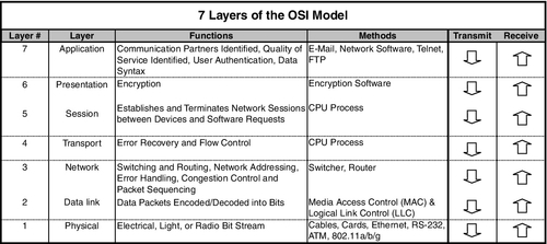
The important point to understand is that in any network today, for TCP/IP messages each packet is encapsulated (enclosed) seven times and, when received, is decapsulated seven times. Each encapsulation involves checking and packaging to make the trip a sure and safe one for the data. Each decapsulation reverses that process:
• Data begins its trip at layer 7, the application layer—software program, Microsoft Word™, etc.
• It is passed down to layer 6, the presentation layer, which adds data compression, encryption, and other similar manipulations of the data.
• It is then passed down to layer 5, the session layer. This provides a mechanism for managing the dialog between the two computers, including starting and stopping the communications and what to do if there is a crash.
• From there, it goes to layer 4, the transport layer (TCP). This layer ensures reliable communications between the machines. The packet changes from data to segments in the TCP layer.
• Down to layer 3, the network layer (IP), where error control and routing functions are described. The segments are combined or broken up into defined-sized packets at the IP layer. Routers are layer 3 devices.
• Down to layer 2, the data link layer, where functional and procedural means to transfer data between network entities and detection and correction of errors that could occur on the lowest layer take place. It is on this layer that the addressing of exact physical machines, each with their own media access control (MAC) address, is found. Each digital device attached to any network has its own unique MAC address, allowing sure identification that the device is authorized for connection to the communication or network. Network switches are layer 2 devices.
• Finally, down to layer 1, the physical layer, including cable, voltages, hubs, repeaters, and connectors.
TCP/UDP/RTP
One of the major advantages of TCP/IP is that it is able to fix bad communications. It does this by keeping track of packet lists for a given communication. Andrew G. Blank, author of TCP/IP Foundations,2 uses a wonderful illustration of a children’s soccer team at a pizza parlor with an attached game arcade:
Let’s say that I take my son’s soccer team to an arcade and restaurant for a team party. I have the whole team outside the arcade. My task is to get the team to the other side of the arcade, to my wife who is waiting for them in the restaurant. In this analogy, the team represents the complete file on one host, and each child represents a data packet. One of my goals is to lose as few of the kids as possible.
While we are standing outside, it is easy to put the team in order; all the children are wearing numbered jerseys. I tell the kids that we will meet on the other side of the arcade in a restaurant for pizza and that they should all move as fast as possible through the arcade and to the restaurant.
After I open the door and say “Go,” the kids enter one at a time. Entering the arcade one at a time represents the fragmenting and sending of the file. Just as each of the kids has a numbered jersey, each packet has a number so that the receiving host can put the data back together.
Now picture a dozen 6-year-olds moving through the arcade. Some of the children will take a short route; others will take a long route. Possibly, they’ll all take the same route, though it is much more likely that they will all take different routes. Some will get hung up at certain spots, but others will move through faster. My wife is in the restaurant waiting to receive the team. As they start arriving at the restaurant, she can reassemble the children (packets) in the correct order because they all have a number on their backs. If any are missing, she will wait just a bit for the stragglers and then send back a message that she is missing part of the team (file).
After I receive a message that she is missing a child (a packet), I can resend the missing part. I do not need to resend the entire team (all the packets), just the missing child (packet or packets).
Please note, however, that I would not go look for the lost child; I would just put the same numbered jersey on a clone of the lost child and send him into the arcade to find the restaurant.
TCP is designed to reconstruct lost packets so that an entire communication is intact. This is very important for files such as employee records, word processing files, and spreadsheets, where a missing packet can cause the whole file to be unreadable.
UDP
For video and audio, another protocol is required. TCP can cause problems with audio and video files because its attempt to resend lost packets results in portions of the communication occurring out of place and therefore in the wrong sequence, making the video or audio communication intelligible. The human eye and ear are very good about rebuilding lost portions of communications. Imagine a restaurant in which you are overhearing a conversation at an adjacent table. You may not be able to hear the entire conversation—not every word because of the noise from others talking—but you can still follow what is being said.
Instead, what we need is a protocol that will send the data without error correction and without attempting to resend lost packets. That protocol is User Datagram Protocol (UDP). UDP is called a connectionless protocol because it does not attempt to fix bad packets. It simply sends them out and hopes they arrive. The transmitting device has no way of knowing whether they do.
UDP and its partner, Real-Time Protocol (RTP), work together to ensure that a constant stream of data (hence the term streaming data) is supplied for a receiving program to view or hear. RTP is used for audio and video. Typically, RTP runs on top of the UDP protocol.
As an industry default, all network data is called TCP/IP data, whether it is TCP/UDP or RTP. It is kind of like calling any tissue Kleenex™ or any copier a Xerox™ machine. It is not accurate; it is just that everyone does it.
Another important set of protocols that security designers will need to know about are unicast and multicast protocols. These are discussed in detail later in this chapter.
TCP/IP Address Schemes
Each network device has a network card that connects that device to the network. The network interface card (NIC) has a MAC address and a TCP/IP address to identify itself to the network. The MAC address is hardware assigned at the factory when the device is manufactured. It can never be changed. The TCP/IP address is assignable, and it defines where in the network hierarchy the device is located. TCP/IP addresses are used to ensure that communication errors do not occur and that the address represents the logical location on the network where the device resides. TCP/IP addresses are like postal addresses, which identify where a house is on what street, in what neighborhood, in what city, in what state, and in what country. MAC addresses are like the name of the person who resides in the house. The MAC address will change if one replaces a computer with another, but the TCP/IP address can stay the same on the network for the user of the computer so that all messages to that user, worldwide, do not need a new MAC address in order to reach him or her.
There are two versions of TCP/IP addresses, known as IPv4 and IPv6. IP version 4 was the original version under which the whole Internet worked until it was determined that the number of available addresses would soon run out. So a larger array of numbers was defined, called IP version 6. IPv6 can accommodate a very large (virtually infinite) number of connected devices.
In IPv4, addresses are broken down into what is called decimal notation for the convenience of the user. Remember, each address is actually a series of binary data (ones and zeros), but they are grouped together in a fashion that is much easier to understand. Four groups are combined together, separated by decimals. Each group (byte) can be a number from 0 to 255 (a total of 256 numbers). This is an 8-bit value. A typical address can be from 0.0.0.0 to 255.255.255.255. IPv4 provides for in excess of 4 billion unique addresses. IPv6 replaces the 8-bit value with a 12-bit value. (0.0.0.0 to 4095.4095.4095.4095). The IPv6 address range can be represented by a 3 with 39 zeros after it. It is a large number. IPv4 is still adequate for today’s networks, but IPv6 is coming.
Briefly, the first one or two bytes of data, depending on the class of the network, generally will indicate the number of the network. The third byte indicates the number of the subnet and the fourth byte indicates the host (device) number on the network. The host cannot be either 0 or 255. An address of all zeros is not used because when a machine is booted that does not have a hardware address assigned to it, it provides 0.0.0.0 as it addresses until it receives its assignment. This would occur for machines that are remote booted (started up) or for those that boot dynamically using the Dynamic Host Configuration Protocol (DHCP). The part of the IP address that defines the network is called the network ID, and the latter part of the IP address is called the host ID.
Regarding the use of automatic or manual device addressing, we recommend manual addressing for security systems. DHCP incurs the possibility of security breaches that are not present with static addressing.
Networking Devices
Security system digital networks are composed of five main types of network devices.
Edge Devices
Edge devices include digital video cameras, digital intercoms, and codecs. These are the devices that for the most part initiate the signals that the rest of the system processes. One exception to this is that codecs can also be used to decode digital signals and turn them back into analog signals for viewing of digital video signals or listening to digital audio signals. The most common use of the decoding codec is for security intercoms, where an analog intercom module is a must in order to hear and speak from the console.
Communications Media
Digital signals are communicated either along cable or wirelessly. The most common type of wired infrastructure is an Ethernet cabling scheme. Although other types exist (e.g., ring topology), none are prevalent. Ethernet is a wired scheme that allows many devices to compete for attention on the network. It is designed to handle collisions that occur when two or more devices want to talk simultaneously.
Devices contend for attention and are granted permission to speak while all other devices listen. Contention can slow a network, reducing its throughput. A network can be segmented by switches and routers to reduce contention and regain efficiency.
Ethernet is defined under IEEE3 Standard 802.3. Ethernet classes vary by speed, with the slowest being 10Base-T [10 megabits per second (Mbps)]. Fast Ethernet is called 100Base-T and operates at 100 Mbps. Gigabit or 1000Base-T operates at 1 gigabit per second (Gbps). Wiring distances depend on wire type and speed. Ethernet is wired using unshielded twisted pair (UTP) four-pair wiring on RJ-45 connectors. Category 5 or 5e (Category 5 Enhanced) wiring is used for 10Base-T, 100Base-T, and 1000Base-T (up to 328 ft). Category 6 wire is useful for 1000Base-T runs up to 328 ft. For 1000Base-T connections, all four pairs are used, whereas for 100Base-T connections, only two pairs of wires are used.4
Category 5, 5E, and 6 cables use four pairs, where the colors are
• Pair 2—white/orange
• Pair 3—white/green
• Pair 4—white/brown
The second most common type of wired infrastructure is fiber optic. These come in two types, single mode and multi-mode. When told that the difference between the two is the number of signals they can carry, newbies often think that the single mode will carry one and the multi-mode will carry more. In fact, just the opposite is true.
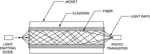
Single-mode fiber is based on a laser, whereas multi-mode may use either a laser or a light emitting diode (LED) for a signal source (Fig. 11.2). Multi-mode fiber is typically plastic, whereas single-mode fiber is made of glass. Multi-mode fiber has a large cross-sectional area relative to the wavelength of the light being transmitted through it, typically either 50 or 62.5 μm (micron) fiber diameter compared to 1.3 μm for 1300-nm modulated light frequency. Accordingly, multi-mode bounces the light off the inside of the fiber (Fig. 11.3). As the light bounces off the walls of the fiber, it takes many different paths to the other end, which can result in multiple signals at the other end. The result is a softening or rounding of the square digital signal. Over distance, the signal becomes more difficult to read at the receiver—thus the limited distance of multi-mode fiber. Distance is also a factor of bandwidth. You can use multi-mode at longer distances with less speed. Fast Ethernet (100 Mbps) can travel farther than gigabit Ethernet (1000 Mbps). Check the manufacturer’s specification sheets both for the fiber and for the transceivers you intend to use for exact limits based on speed.
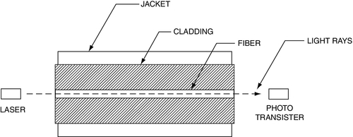
Single-mode fiber is made of glass, and it pipes the laser directly down the middle of the glass tube like a waveguide.5 This is because single-mode fiber has a small cross-sectional area (8 or 9 μm) relative to the frequency of the light being transmitted through it (1.3 μm at 1300 nm). The laser can carry multiple signals on its carrier.
The most commonly used frequencies are 1550, 1310, and 850 nm. The 1550 and 1310 nm frequencies are very common to single-mode fiber, and 850 nm is most commonly used in multi-mode fiber. The 1310 and 1550 nm frequencies are exclusively transmitted using lasers, and the 850-nm frequency is exclusively transmitted using LEDs. By using multiple frequencies (1310 and 1550 nm), it is possible to transmit and receive bidirectionally over a single fiber. Although this is not a common practice, some transceivers can accommodate two frequencies on a single fiber, especially with single-mode fiber. Typically, 1300 nm is used to send and 1550 nm is used to receive at one end and vice versa at the other end. More commonly, bidirectional communication is accommodated by using two separate fibers on the same frequency. No standard has been developed for multiple frequencies on a single fiber on multi-mode cable, but at least one security fiber-optic company has developed a fiber-optic media converter that can both transmit and receive on a single multi-mode fiber using two separate frequencies.6
Manufacturers have long since surpassed the IEEE 802.3z standard in terms of the distances served. Multi-mode fiber distances are typically limited to 1640 ft for fast Ethernet connections. Gigabit speeds are commonly limited to 1000 ft. Single-mode fiber distance limitations vary and can commonly be 43–62 miles with economical equipment7; much farther distances are possible (up to 500 miles) with more sophisticated media converters.8 With commonly available equipment, it is possible to achieve distances of up to 93 miles with either single-mode or multi-mode at 100Base-T speeds and 75 miles at 1000Base-T speeds.9
Last, single-mode transceivers and fiber are more costly than their comparable multi-mode equivalents. The cost delta can be vast. Use multi-mode for shorter distances (e.g., on a campus) or where cost is a factor. However, the cost delta can sometimes be worth it if there is available single-mode fiber in the ground on a campus and the only cost to mount up the system is that of the transceivers.
Gigabit switches and routers are usually supplied with either single- or multi-mode fiber ports. This is the preferred connectivity method over the use of separate transceivers.
TCP/IP signals can also be communicated via radio, microwave, or laser. The most common type of radio communication network is in the 802.11 band. 802.11 is available in two major categories, backhaul or client service. The backhaul type is delivered by 802.11a, whereas client services are often provided by 802.11b/g/i. 802.11a makes available 10 channels, and with the correct antennas one can use all 10 channels in the same airspace. 802.11b/g/i are very similar but differ by the bandwidth provided and the level of security implemented. 802.11b provides 11 Mbps maximum, whereas 802.11 g/i provide 54 Mbps. It is possible to find 802.11 g devices that provide 108 Mbps. These are full-duplex devices that use a separate transmitter and receiver to double the bandwidth. This function is very common in 802.11a, which also provides 54 Mbps per available channel. 802.11b/g/i have 13 available channels, but cross-traffic is a problem. Do not plan to use more than 6 channels in a single airspace. 802.11n has even more capabilities because it uses multiple antennas to increase speed and accuracy of the signal. Signal speed rises from 54 Mbps for 802.11 g/i to 600 Mbps for 802.11n. Security improvements are also seen in 802.11n. 802.11n is recommended for wireless security systems wherever possible.
Network Infrastructure Devices
Network infrastructure devices comprise those devices that facilitate the movement of data along the communications media. Digital cameras and codecs connect to a digital switch in order to get on the network.
Hubs
This section is for information only. Hubs should not be used in any digital security infrastructure, because they have the potential to introduce significant problems into the system. The most basic type of network device is a hub. A hub is simply a device with Ethernet connectors that connects all devices together in parallel with no processing. A few hubs have power supplies and provide LEDs to indicate port activity, but do not confuse this with active electronics. Hubs are dumb. Hubs have no ability to control the collisions that naturally occur in Ethernet environments, so when too many devices are connected together on a hub, the network throughput suffers due to delays caused by the collisions. It is inadvisable to use a hub for all but the simplest networks (less than eight devices). Hubs offer no security services. Hubs are OSI level 1 devices. Hubs connect devices. Let me emphasize again that hubs should not be used in any IP-based security system. The very act of introducing a hub into a system (typically to expand the number of connected devices when a digital switch has reached its full capacity), can cause the entire system to become unstable and crash. Do not allow hubs in your system design!
Switches
A switch is a smart hub. Unlike a hub that presents each signal to all connected devices, a switch is able to read the TCP/IP packet header and direct the signal to the appropriate port(s). Switches are OSI level 2 devices. Switches control where data may go. Switches for use in digital security systems must have sufficient buffer memory to accommodate large video packets. Better quality switches are required. I do not recommend the use of “economy” switches, because they can also introduce problems into the system, especially where mega-pixel cameras are in use.
Routers
Routers are one step up from switches. In addition to directing the traffic of individual ports, they can in fact make decisions about data that is being presented to them and can decide if that data belongs on that section of the network. Routers can create subnets of the greater network. This allows functions and devices to be segmented into logical groups. Subnets reduce the overall amount of network traffic, making the network operate more efficiently. Subnets can be used to separate different sites, campuses, and buildings and are sometimes even used to separate edge devices from client workstations. Routers control what data may go. Routers must be designed to accommodate the required throughput plus a factor of two. So if a router is to pass 4 gigabits of data, it should have a design capacity of 8 gigabits.
Firewalls
Firewalls are used with routers to deny inappropriate data traffic from another network. Firewalls can be configured in either hardware or software. Security systems that are connected to any other network should be connected through a firewall. Otherwise, a security system is not secure and, thus, the facility will not be secure. Firewalls deny malicious data. Remember please that firewalls must also be designed to accommodate the required throughput plus a factor of two. So if a firewall is to pass 4 gigabits of data, it should have a design capacity of 8 gigabits.
Intrusion Detection Systems
Intrusion detection systems (IDSs) can also be either hardware or software devices. IDSs continuously monitor the traffic into and out of the network to detect any unauthorized attempt to gain access to the network. The IDS will warn the network administrator of the attempt and provide insight into how the attack attempt was executed in order to adjust the firewall to limit future attempts using that method. IDSs warn the system administrator about attempts to probe the network or insert malicious data.
Servers
Servers process and store data for use by workstations. For security systems, there are several possible types of servers. These may be combined on a single machine or may be distributed across several physical servers.
Directory Service Server
The directory service is an index for all workstations to use to find the data for which they are searching. It tells them where to find the correct camera, intercom, or archive stream. Additional functions may include Internet information services (IISs), domain name service (DNS), and other network management services.
Archive Service
The archive server stores data for future reference.
Program Service
The program service allows programs to reside on the server rather than on the workstation. This is not recommended because the few dollars saved result in a slower system.
FTP or HTTP Service
This is very useful for remote monitoring and retrieval of data from a remote site to a central monitoring station, for example, or for a manager to “look in” on a site.
Email Service
Servers can send or manage email.
Broadcast Service
Servers can broadcast alerts or alarms to pagers, cell phones, loudspeakers, printers, and other devices.
Workstations
Workstations provide a human interface to the network. Workstations can be either single purpose or multiuse, serving other types of programs and other networks. For large sites, it is often best to use single-purpose machines on a dedicated network. Workstations can support many video monitors in order to display digital video, alarm/access control, intercom, report and analysis software, browser, and other services. We often design systems that have up to six monitors per workstation. It is also possible to operate more than one workstation with a single keyboard and mouse in order to support more functions than a single workstation can handle. This is often necessary for systems that do not prioritize intercom audio over video.
Printers
Printers can be connected either to a workstation or directly to the network, where they can serve multiple workstations.
Mass Storage
Digital video systems can store a lot of data—much more data than any other type of system. It is not unusual for us to design systems with many terabytes of video storage. This amount of storage cannot be contained in a single server or workstation. There are two ways of extending the storage: network attached storage (NAS) and storage area networks (SANs). The names are so similar that they can be confusing, but the differences are extensive.
NAS units include a processor and many disk or tape drives (or a combination of both). They are typically configured to “look” like a disk drive to the system, and they connect directly to the network, just like a server or a workstation. This means that a large volume of data traffic is on the network to feed the NAS.
A SAN is on its own network in order to separate the vast amount of traffic it generates away from the common network. This is a good idea, even for small systems. SANs can be created easily by adding a second NIC to the archive server and connecting the SAN to that NIC.
See information on how to calculate required storage for an integrated digital security system at the end of this chapter.
Network Architecture
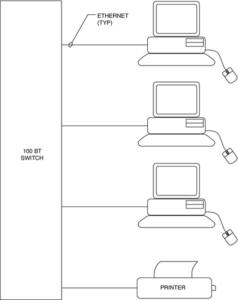
Simple Networks
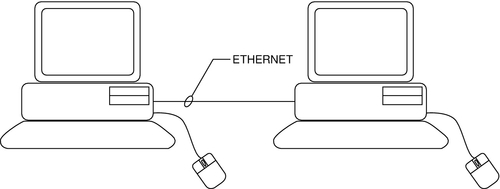
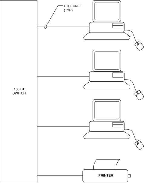
The simplest networks connect two devices together on a cable (Fig. 11.4). Basic networks connect several devices together on a single switch. This creates a local area network (LAN) (Fig. 11.5). From there, tree architecture is common. There may be a single workstation/server (one computer serving both purposes) that is connected through one or more switches to a number of cameras, intercoms, codecs, access control panels, for example (Fig. 11.6).
Advanced Network Architecture
Backhaul Networks
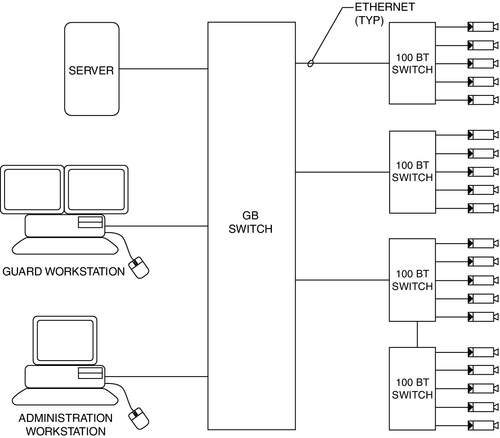
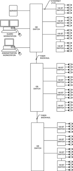
Beyond simple tree architecture, as network size grows, it is common to create a backhaul network and a client network. This can be achieved in its simplest form with gigabit switches. A simple gigabit switch is equipped with a number of fast Ethernet (100 Mbps) ports to connect edge devices, such as cameras, codecs, intercoms, or access control panels, and a backhaul connection that supports gigabit (100 Mbps) speeds. The result looks like an organization chart in which the server/workstation is at the top on the gigabit backhaul network and the edge devices (clients) are on the 100 Mbps ports of the switches (Fig. 11.7).
Ring Architecture
Many large security systems use a “ring” architecture to assure reliability and redundancy. Ring networks are typically hierarchical in nature; that is, they comprise a core ring and distribution and edge switches.
In a ring architecture, the network core comprises a ring of very high capacity “core switches” (these are typically capable of 10 gigabits or more). Core switches usually connect only core devices to thec ring. Core ring‒connected devices commonly include only distribution switches and servers, IP-intercom matrix switches, routers, and firewalls. Distribution switches typically connect and gather edge switches, and edge switches connect IP-cameras, IP-encoders and decoders, access control panels, IP-intercoms, and workstations. There may also be some use of routers and firewalls at this level. Some designers connect workstations directly to the core or distribution switches.
A common ring architecture system may connect hundreds to thousands of cameras, access control panels, and intercoms. Combined data throughput can often grow to many gigabits of data. It is not uncommon to see core rings that handle 20 to 100 gigabits of raw data; it is very common to see 10-gigabit core rings.
Ring architectures are especially useful where redundant servers must be placed on remote locations or buildings on a campus or where multiple campuses are connected together. Each campus location can be assigned its own core or distribution switch(es). Thus, a full set of redundant servers and storage can exist in a remote building on the core ring and assure full service to the entire system should a catastrophe take down the primary servers.
As the use of mega-pixel video cameras grows, the use of large-capacity core ring networks will become much more common.
Subnets
A subnet is basically virtual LAN (VLAN) that is a logical subset of the overall LAN. Subnets are used for several reasons, the most common of which are to limit network bandwidth to manageable levels and to minimize traffic that is not appropriate for certain devices, such as segregating buildings on a campus.
Subnets to Limit Network Traffic
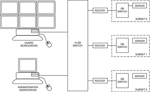
As network bandwidth increases, it can task the switches to a point at which they begin to drop packets. I recommend that you do not pipe more than 45% of the rated bandwidth of any device because the rated bandwidths are based on normal network traffic, not streaming data such as video. Stay under 45% and you will not usually experience problems. A VLAN is created by joining two or more networks by routers. Typically, routers are placed on the backhaul network, and they in turn may have their own backhaul networks that serve many edge devices. Architected thus, no single subnet will have too much traffic on it (Fig. 11.8).
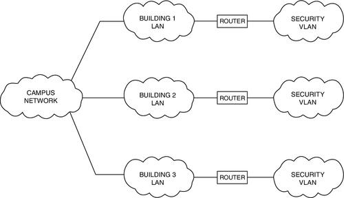
Subnets to Segregate Network Traffic
When a security system serves many buildings on a campus, it is not useful to have the traffic of one building on the network of others. So each building can be joined to the main backhaul network through a router such that its traffic is limited only to data that are relevant to that building alone (Fig. 11.9).
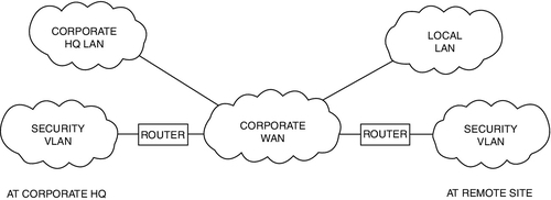
The security system could be placed on the larger organization’s network as a subnet. Subnets can be integrated onto a larger network in a way that would seem by their physical connections to be blending the two networks, whereas in fact they operate as completely segregated networks, totally isolated from each other by routers and firewalls. Be advised that enterprise security systems using large amounts of digital video can tax the bandwidth of virtually any organization’s business network architecture to the breaking point. It is often advisable to physically segregate the networks. Additionally, when the security system is placed on the organization’s network, significant additional effort is required to secure the security system network from the organization’s network, which will never likely be as secure as the security system network, notwithstanding the assertions of the organization’s information technology department (Fig. 11.10).
Blending Security and Business networks: VLANS
Often, a security designer will be asked to design a security system that operates on an existing business network. This is done using Virtual Local Area Networks (VLANS). VLANs are global subnets. Like a subnet, a VLAN segregates a data channel for a specific purpose or group. Unlike a subnet, which is a hierarchical daughter of a physical LAN, a VLAN can coexist across the mother LAN as a VLAN as though there were two separate sets of hardware infrastructure. It does this by operating on a dedicated port to which only the VLAN has privileges. Therefore, cameras, intercoms, and access control system controllers can be plugged into the same managed switch with workstations and printers of the organization’s business LAN, and when the security devices’ ports are dedicated to a security VLAN, those devices will not be apparent or accessible to the users or the LAN. This is the best methods for sharing networks between security and business units.
Be aware that adding a security system to an existing business network can cause havoc with both systems. The two types of networks have entirely different operating environments and maintenance and security requirements. Business networks require regular maintenance, usually requiring scheduled downtime. Security systems must operate continuously without any interruption 24 hours per day, 7 days per week, and 365 days per year. Business networks have many users and as such are subject to constant threat of injected viruses and malware, usually injected by a thoughtless user clicking on a dangerous email or URL link. A security system has comparatively very few users and those users are not receiving emails or processing many common types of documents that are prone to virus and malware infections. The biggest threat to the security system network is the business network. Business networks store most files on servers, and those files are infrequently pushed back and forth between servers and workstations. Security system networks have hundreds to thousands of edge devices such as video cameras that continuously push vast amounts of data to the servers and mass storage media, and comparatively little data is drawn from servers to workstations.
These differences in operation and architecture require entirely different design approaches. For example, some common security system software will not work well on a network configured with common anti-virus software because the anti-virus software is constantly trying to scan each individual video packet before it allows it to the server. This can slow down network throughput to a crawl and indeed can regularly crash the security system network.
It is important that the IT director fully understand these differences in operational needs before commencing to blend business and security networks onto the same physical infrastructure. I have seen IT directors nearly faint when they discovered that they need a firewall capable of 20 gigabit throughput. Believe me that has a profound impact on network cost.
Network Configurations
A network is composed of a series of TCP/IP devices connected together. There are a variety of ways to do this, and each has its own advantages and limitations.
Peer-to-Peer
The most basic network is a stand-alone peer-to-peer network. Peer-to-peer networks are created by connecting each device together through a hub or switch. Each computer, codec, or access control panel is equal in the eyes of the switch. This is adequate for very small networks (Fig. 11.11).
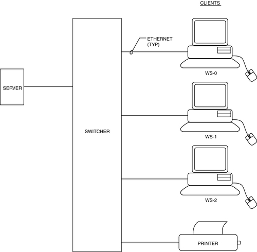
Client/Server Configuration
As network sizes expand, a client/server configuration is preferred. Major processing is performed in one or more servers, and the human interface is accommodated with client devices or workstations (Fig. 11.12). Cameras, intercoms, access control readers, locks, door position switches, request-to-exit devices, and alarm triggering devices, for example, are all human interface devices, as are guard and lobby workstations and intercom master stations. Typically, the human interface devices are connected to processing devices that interface to the network via TCP/IP connection, usually Ethernet. These may include codecs and alarm/access control panels.
On larger networks, it is common to use multiple servers. Commonly, there will be multiple archive servers. It is also common to use a second set of servers as a backup to the primary servers in case of a disaster that disables the primary servers. This allows for remote access to the data up to the second of the disaster in order to analyze the event and to provide a business continuity record of all network data.
Creating Network Efficiencies
One of the major advantages of enterprise security systems is the opportunity for remote monitoring of distant buildings. This often requires blending the security system network with the organization’s business network.
The most common requirement is to monitor remote sites. It is not necessary to send all of the data from the monitored site to the site doing the monitoring. The monitoring center only needs to see the data it wants to look at. When you are watching a sports broadcast on TV on channel 11, you do not usually care much about the opera playing on channel 4. Likewise, it is advisable to attach the remote monitoring center only to those data that are relevant at the moment. You do not need to send the video of all the cameras all the time. Using this method, great efficiencies can be gained. Overall network bandwidth can be limited only to the cameras being monitored. I use cameras as an example here because they consume the most bandwidth. Obviously, alarms must be connected continuously in order to report in a timely fashion.
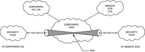
There are two very efficient ways to remotely monitor over a business network: browser and virtual private network (VPN). A browser connection is quick, easy, and does not consume any bandwidth when it is not sending data. It consumes only what it displays. One can configure simple monitoring centers with browser connections to the remotely monitored sites. When one wants to see the site, one makes the connection; otherwise, the connection is closed. However, browser connections consume data even when minimized, regardless of whether the data is sent to the screen. This will consume both network bandwidth and workstation processing power. So it is advisable to close browsers when not being viewed. Alarms can be sent on a separate data link to alarm monitoring software that is always open. These consume virtually no bandwidth, so they can stay open at all times. Browsers should be run under https rather than http (https is a higher security environment), and secure socket layer encryption is often advisable to ensure the security of the system being monitored. Even so, browsers are not as secure as VPNs. Browser connections can be hacked.
A VPN can open and close like a browser, but it has vast advantages in terms of network security. A VPN is a tunnel between the server being monitored and the server that is requesting its data. That tunnel is firewalled and encrypted. It is as good as gold for security. It takes extremely high skill levels to hack a VPN. The disadvantage of VPNs is that they utilize a fixed bandwidth. When a VPN connection is open, that amount of bandwidth is in use regardless of the number of cameras being monitored. That bandwidth is no longer available for the business network connection to that site (Fig. 11.13).
Digital Video
Cameras and Codecs
Digital video cameras are available in two types: digital cameras or analog cameras with digital codec converters. Digital cameras are an emerging trend. Most cameras available are still analog, and to use them in a digital video system, one must add a codec.
Digital cameras do not provide a baseband video output (PAL or NTSC). They are equipped with either a USB or Ethernet connection. They issue digital images directly.
A codec is a device that converts analog to digital. There are a variety of codec types, in the following categories:
• Number of channels: Single-channel codecs support only one camera. Multiple-channel codecs support multiple cameras. Single-channel codecs are the best choice when the wiring infrastructure is predominantly digital, and multiple-channel codecs are a good choice when most of the wiring is analog. Multiple-channel codecs facilitate wiring a number of cameras to a single point where perhaps an analog video switch used to be, its space now being occupied by codecs.
• Number of video data streams: Many codecs output only one data stream per camera. Some support two, which is better. Each data stream can typically be configured to adjust the frame rate and resolution. With two data streams, you can adjust one for live viewing and the second for archiving. You might adjust the live viewing data stream at, for example, 15 frames per second (fps) and at medium resolution and the second stream at 4 fps and high resolution. Generally, it is desirable for archiving retrievals to display higher resolution than for live viewing because you are looking for detail rather than just a transient image.
• Audio/no audio: Some codecs support an audio channel and some do not. The audio channel will be its own separate data stream, usually under the same TCP/IP address.
• Input and output contacts: Many codecs also provide one or more dry-contact inputs and outputs. These are useful to control nearby devices or to cause some activation in the system. For example, it could be used to unlock a door or to cause an alert if a door opens.
• Compression schemes: Different codecs use different compression schemes, see below. Common compression schemes include the following.
A basic digital image such as a raw video frame such as a BMP (bitmap) or TIFF (tagged image file format) is composed of a large number of picture elements called pixels, with each pixel having its own data attributes. Attributes may include black/white balance, color and hue, and gamma (luminance). These images take a lot of data space. It is common for a single raw or BMP image to require several megabits of data. These large files are not useful for network transmission because they use too much network bandwidth. The images can be compressed (made into smaller packets) literally by throwing away useless data.
There are three major types of digital video compression schemes: MJPEG, MPEG and H.264. JPEG (Joint Photographic Experts Group) is a scheme that results in a series of fixed images, strung together like a movie. MJPEG stands for Motion-JPEG and is simply a series of JPEG frames strung together as video. MPEG (Moving Pictures Experts Group) is a similar group that from its inception created compression algorithms specifically meant for moving pictures.
• MPEG-1 was the earliest format and produced video CDs and MP3 audio.
• MPEG-2 is the standard on which digital television set-top boxes and DVDs are based. This is very high-quality video.
• MPEG-3 (MP3) is an audio codec.
• MPEG-4 is the standard for multimedia for the fixed and mobile web.
• There are also MPEG-7 and MPEG-21, which are for future projects.
Digital video security codecs and cameras are typically either MJPEG (a series of JPEG images strung together as a stream of data) or MPEG-4.
BMP images are resolution dependent. That is, there is one piece of data for each separate pixel.
JPEG compression basically replicates similar data rather than storing it. For example, if there were a picture of a flag, the red portion might only be stored in a single pixel, but there will be a note to replicate the red pixel everywhere it existed in its original BMP file. This can achieve very high compression compared to BMP files.
MPEG compression takes this process one step further. For a sequence of images, the first one is stored as a JPEG image, and each subsequent image stores only the differences between itself and the previous image. The first frame is called an “I-frame,” or “key frame,” and subsequent frames are called “P-frames.” I-frames are just a JPEG image. An I-frame becomes the reference point for the subsequent image compression of P-frames. P-frames display just the difference between the original I-frame and what the camera is seeing now. By storing only the difference, and not say, a static background, vast efficiencies are possible. When too much updating is occurring, the process stores a new I-frame and starts the process all over again. The MPEG protocol results in very efficient file compression. H.264 takes this process one step further by adding B-frames. While a P-frame stores the difference between the original I-frame and what the camera is seeing now, the B-frames store only the difference between the I-frame and subsequent P-frames. So, just the most minor differences are stored and not differences from the I-frame that were stored in previous P-frames. This is a very, very efficient compression algorithm. While H.264 is very efficient for storage, it requires far more processing power to display, because the display-rendering engine must reassemble not just a single I-frame and a single P-frame, but rather an I-frame, and all subsequent P-frames and B-frames, so there is a lot more work to displaying H.264 than MPEG-4 images.
Advantages and Disadvantages
Each JPEG image is a new fresh image. This is very useful where the frame rate must be very low, such as on an offshore oil platform with a very low-bandwidth satellite uplink, or where only a dial-up modem connection is available for network connectivity. I used JPEG on an offshore platform with only a 64 kb/s satellite connection available. MPEG is most useful where there is adequate data bandwidth available for a fast-moving image but where it is desirable to conserve network resources for future growth and for network stability.
More on Compression Algorithms:
• MJPEG: MJPEG is a compression scheme that uses the JPEG-compression method on each individual frame of video. Thus each frame is an entire picture.
• MPEG-4: MPEG-4 is a compression scheme that uses a JPEG “Initial Frame (I-Frame),” followed by “Partial Frames (P-Frames),” each of which only addresses the pixels where changes have occurred from the previous frame. After some period of seconds, enough changes have occurred that a new I-frame is sent and the process is started all over again.
• H.264: H.264 is a compression scheme that operates much like MPEG-4 but that results in a much more efficient method of storing video, but H.264 relies on a more robust video-rendering engine in the workstation to view the compressed video.
Digital Resolution
Digital image resolution is the bugaboo of digital video. You can never have enough resolution. However, high resolution comes at a high price in network bandwidth usage and in hard disk storage space. There is always a trade-off between resolution and bandwidth/storage space. Thankfully, the cost of storage keeps dropping (I think we will soon see terabyte hard drives blister-packed for 99 cents), but I think that network bandwidth will always be a problem.
JPEG resolution is measured in pixels per inch (PPI). Proper resolution is required for good viewing. Ideally, you should be displaying one pixel of video image onto each pixel on the video monitor. If you display a JPEG image at a greater size on paper or screen than its native resolution, you will see a very fuzzy image (Fig. 11.14). Common file sizes are from 120 × 160 to 720 × 480. Larger sizes are available with even higher resolution.

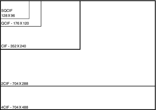
MPEG and H.264 resolution are measured in CIF (Common Intermediate Format). In NTSC, CIF provides 352 × 240 pixels. In PAL, it provides 352 × 288 pixels. The lowest resolution MPEG image is a quarter CIF (QCIF) at 176 × 120 pixels, followed by CIF, 2CIF (704 × 240, NTSC) and (704 × 288, PAL), and finally 4CIF (704 × 480, NTSC) and (704 × 576, PAL). 16CIF will soon be available with very high resolution (1408 × 1152 for both formats), and there is also an amazingly low-resolution SQCIF (128 × 96, NTSC). Most digital codecs provide CIF, 2CIF, and sometimes 4CIF resolutions (Fig. 11.15).
Frame Rates
In order to see moving images, they have to move. Frame rate is the rate at which one frame of video is replaced by another. The speed at which this occurs is measured in frames per second (fps). Some unique applications result in very slow frame rates of seconds per frame.
The human eye can visualize real-time motion as low as 12 or 13 fps. A minimum frame rate of 15 fps is recommended for real-time images. Many users prefer 30 fps because that is what is displayed on analog video. However, that frame rate is not required unless objects are moving rapidly.
Like resolution, frame rates affect both bandwidth and storage capacity, in direct proportion to the fps.
Display Issues
Display Parity
One of the problems that the security industry has not dealt with is that of display parity. Display parity is achieved when the number of pixels being sent to a screen is exactly the same as the number of pixels on the screen.
If one is displaying nine cameras in a window on a 20-in. LCD high-resolution screen, one might have only 160 × 120 pixels available on the screen for each image. Why would one want to send a 4CIF image (704 × 480) to that number of pixels? Why indeed? What happens to all those extra pixels? They are wasted, thrown away. The problem is that they are thrown away on the screen. They occupy tons (if that is a measure of screen processing) of central processing unit (CPU) and video card processing power before it gets thrown away on the LCD monitor.
No problem, you say? Who cares? You do, if you are smart. Here is the problem. A 4CIF image generates 337,920 pixels. Each individual pixel requires a lot of CPU processing power and many more graphics processing units (GPUs). Both CPU and GPU are consumed for each pixel. The original supercomputer, the Cray-1, developed at Los Alamos National Laboratory in 1976, was capable of 80 megaflops of processing power. (Flops is a unit of CPU or video card processing effort; it is an abbreviation of floating point operations per second.) Although there is not a direct correlation between flops and pixel processing (there are approximately 40 variables involved in the calculation, making a calculation essentially meaningless), you can rely on the fact that it takes a lot of processing power to process video to the screen or archive. At 30 fps, the computer is processing 10,137,600 pixels (10.1 megapixels) for each image at 30 fps. Remember, we were displaying nine images. That calculates to 91.2 megapixels per second, and that is just for the video. You are also running the video application, and on larger systems you are also processing audio for the intercom, alarm/access control, and perhaps other data. One can easily exceed 100 megapixels being processed per screen on one’s desktop. For 16 images, at 30 fps at 4CIF the number exceeds 160 megapixels being processed in real time, and that is just on one screen. That will crash virtually any workstation regardless of processing power. High resolution times high frame rate times many images can easily equal a computer crash. Additionally, pixels thrown away on the screen present a rough look to the images. Without a doubt, display parity results in the best appearance.
The ideal process here is to have software in the server that disposes of unneeded pixels before they are sent to the workstation. This approach of prerendering the video image has many advantages in quality of display and network throughput. However, to date, after much haranguing of video management software manufacturers on my part, only one software vendor that I know of is even thinking about this problem.
So what is a designer to do? Well, there are only three variables available to manage this problem: image resolution, frame rate, and processing power.
First, there is little need to display images at 4CIF or greater unless one is displaying at full screen. It is better to send live images to the screen at 2CIF because the extra pixels will just be thrown away and no good will be served by the extra resolution that is consuming unneeded network bandwidth and processing power.
Second, archived images do not usually need to be displayed at 15 or 30 fps. Use a slower speed and higher resolution for archived video. When one calls up archived video, one is usually interested in seeing as much detail in the image as possible. Use higher resolution and lower frame rate. There are a few applications in which this is not appropriate, such as for casino environments, where fast-moving hands hold the secret to cheating.
Finally, I usually design systems with lots of processing power, typically dual Xeon™ computers as workstations. Dual-core processors better that. Expected advances will put teraflops of graphics processing power at hand.
Storage Issues
As with display, storage consumes lots of data and processing power. Unless there is a compelling reason otherwise, it is best to store data at a slower frame rate than for live viewing. This not only saves disk and tape space but also helps ensure growth capacity.
Managing Data Systems Throughput
Network throughput management requires math, sometimes lots of math, but it is a good investment. I do not recommend running any network or network segment beyond 45% of its rated capacity. If there is a segment that has a capacity of 100 Mbps, keep traffic to 45 Mbps. If it is a gigabit backhaul segment, keep the traffic to 450 Mbps. If you have to exceed 450 Mbps, it is better to use multiple gigabit communications paths or a 10 gigabit path.
There are two ways of managing network throughput: more capacity and network segmentation. The cost/benefit is usually in favor of network segmentation.
By segmenting the network into subnets or VLANs, one can maintain the traffic at manageable levels. All traffic does not have to be everywhere. By recording video remotely rather than centrally, traffic is diminished. If a backup is needed, or if there is a concern about the loss of data in remote storage, centralized recording is possible at far greater cost in network traffic and infrastructure cost. An alternative is “neighborhood” archiving, where a few sites are gathered together for storage, limiting traffic on the enterprise network.
System Architecture
Servers
Servers provide the guidance and direction for the entire system and store its activities and history. A server can operate several applications simultaneously, and a server equipped with a dual-core or quad-core CPU can also prioritize those services, ensuring that, for example, intercom calls always go through. Servers provide several basic services.
Directory Service
The directory service provides the routing information to locate cameras, intercoms, and archived video on demand. It also maintains the necessary information for all system devices to communicate effectively.
Directory services can be local or global. In an enterprise integrated security system, the directory service may be both, with a global directory service centrally controlled, and local servers may maintain their own subordinate automatic fail-over directory services in case of loss of communications with the global directory server.
Enterprise integrated security systems also typically use an automatic fail-over server that runs parallel to the main server but in another location, ready to take over its activities immediately upon a failure of the main server.
Archiving Data
The server will typically archive alarm/access control, video, and intercom activity, indexing it by date and time and often correlating video and voice data to alarm and security events so that the operator has immediate access to appropriate video and voice as he or she views alarm activity. Enterprise systems also typically use an automatic fail-over archive server.
Remote Access Services
Web Access
A VPN helps ensure data integrity for offsite Web service connections. Remote access from within the domain is often accommodated by use of a VLAN.
Email and Pager Notification Service
The server software may support email and pager notification. These will require exchange server or similar software or a dialup or Web connection for a pager.
Hardware Configurations
CPUs
Generally, it is appropriate to specify the fastest or nearly fastest CPU available for the server with significant cache memory and a very fast front-side bus.
Memory
More is better. At least 8 GB of RAM should be considered in 2014-era terms. As this book ages, more memory should be considered. As a general rule, fill the workstation RAM to its absolute fullest capacity. You will not regret it, and memory is almost cheaper than candy bars.
Disk Storage
Operating Systems and Programs
All system servers should be equipped with multiple disks, including two mirrored automatic fail-over drives for operating systems and programs, complete with current configurations. These should be kept up to date so if one fails, the other takes over immediately. This is also less expensive than a full hot redundant off-site fail-over server and should be done even when a redundant server is used.
Additional disk slots should be dedicated to data archive up to the server’s capacity. Disks are so inexpensive that it is almost always appropriate to specify the largest disks available. RAID-5 should be considered, configured to 500 GB segments for rapid searching of archived data.
Where additional disk capacity is necessary, external storage capacity should be considered. There are two methods of external storage.
Tape or Disk
External storage is available in both tape and disk. It is generally recommended to use both. Disks can store up to a given time depth. Beyond that, you can store endlessly on tape. For very large storage requirements, a tape carousel automatically handles the process of keeping fresh tapes loaded and used tapes stored, ready for use. The carousel can be expanded to store as much or as little as is appropriate based on network archive usage and the length of time storage is desired.
Network Attached Storage
Network attached storage is external storage that is attached directly to the server switch. This is the least expensive option, but it has a negative effect on network throughput. Accordingly, I do not recommend NAS.
Storage Area Network
A SAN is a separate network on the backside of the server that is dedicated only to moving storage data between servers and the external storage media. There is a perception that SANs are unnecessarily expensive, but this does not necessarily have to be so. A SAN can be created simply by placing an additional NIC in the server and porting archive data out the back to the external storage. Where multiple servers or multiple external storage units are required, a SAN switch handles the task. SANs make the best use of the primary data network over which live data are flowing. They place virtually no additional burden on the live data network, conserving its spare capacity for system growth. SANs are always recommended for external storage, even if there is only one server and one external storage unit.
Workstations
A workstation is a computer used by a person who operates the system. There are a variety of basic workstation types.
Security Monitoring (Command) Workstations
Security command workstations are used in security command centers, typically in enterprise security systems. A security command center typically includes two or more security command workstations and may include an array of large-screen video monitors to support the joint viewing of images by operators at several consoles. These workstations typically include alarm/access control/digital video and security intercoms as well as report writing programs.
Guard or Lobby Desk Workstations
A guard or lobby desk workstation is a single computer dedicated to supporting a guard’s desk duties in a lobby. These may include alarm/access control, digital video, and intercom.
Administrative Workstations
An administrative workstation supports management of an integrated security system, including system configuration, database management, and reports.
Photo ID Workstations
Photo ID workstations are used to create identification badges for use with the access control system. A photo ID workstation typically includes a camera, backdrop, light source, sitting chair, digital camera, and workstation and may include a posing monitor to help the subject pose to his or her satisfaction. On larger systems, there may be several photo ID workstations in a single area.
Access Verification Workstations
On high-security installations, an access verification workstation may be used in conjunction with a man-trap and card reader to ensure that the person passing into a secure area is indeed who he or she claims to be and that his or her credential is valid for the secure area. The access verification workstation displays a photo of the cardholder each time a card is presented. This allows a guard at the workstation to verify that the face is that of the valid cardholder.
Edge Devices
Edge devices include cameras, intercoms, card readers, alarm detection devices, electrified door locks, and request-to-exit detectors. These are the devices that interface with the user. On a typical integrated security system, the edge device connects with a data controller or codec, which converts its native signal (audio/video, dry contact, or data) to a uniform TCP/IP standard. Thus, controllers and codecs are also edge devices. The edge devices typically connect to the system through a data switch.
Infrastructure Devices
Between edge devices and servers/workstations is the digital infrastructure, which connects the system together and manages its communications rules.
Switches
Digital switches are the connection points for almost all system devices. A digital switch is a device that not only provides a connection point but also can manage how each device communicates with the system. A digital switch is like a mail carrier on a mail route, who ensures that each house gets the mail that is addressed to it for the neighborhood it serves.
Switches can segregate communications between devices and manage the priority and limit the bandwidth of the data of different devices. Switches generally have a number of RJ-45 eight-conductor modular jacks (typically 8–48) and can cascade communications in either a ring or tree architecture. The switch must be specified to support the amount of data that is expected to go into its edge ports and out of its infrastructure ports. It is wise not to exceed more than 45% of the rated capacity of any switch for all signals combined, under worst-case conditions. Switches are OSI layer 2 devices, but better switches can also perform OSI layer 3 management functions. These are commonly called “managed” switches. Switches should be able to support IGMP querying and IGMP snooping in order to support video multicast. Ample memory is recommended (at least 100 KB per port), and the switch should be able to support VLAN operation. If the switch may need to become part of a trunk within a VLAN, then it should also be able to support 802.1Q protocol. For outdoor operation, a robust environmental tolerance is needed. The switch should be able to operate from well below freezing (− 10 °F/− 23 °C) to high temperatures (160 °F/70 °C is ideal). These are commonly called “hardened” switches. Redundant power supplies are also recommended.
Routers
Routers manage data traffic at a more global level. Routers are OSI level 3 devices. An edge router is like a local post office that routes mail from one locale to another, where it will be handed off to the neighborhood postal worker (the switch). A router that manages traffic for an entire organization to the Internet is called a core router.
Routers are capable of segregating traffic into subnets and VLANs, creating logical separations of data and making communications within the network much more efficient and secure.
Firewalls
A network firewall is a computing device that is designed to prevent communications from and to some devices in support of an organization’s network security policy.
Wireless Nodes
Wireless nodes are radio frequency transceivers that support network communications. Often, they also incorporate network switches, and sometimes they can incorporate routers and even firewalls. They also commonly encrypt data placed on the wireless link.
Network Communications Speeds
There are four common speeds of network communications:
• 100Base-T: 100 Mbps
• 1000Base-T: 1 Gbps
• 10,000Base-T: 10 Gbps
Cabling
Network cabling can be either wired or fiber optic. Fiber-optic cabling types include single mode and multi-mode.
Wired Cabling
Category 5e and 6 cables are used for network cabling. Both have a native distance limit of 300 ft. Cat5e and Cat6 cables can support 10Base-T, 100Base-T, and 1000Base-T connections, with distance decreasing as the speed increases.
Fiber Optic
Fiber-optic cabling can support faster speeds, longer distances, and simultaneous communications. Unlike wired cable, fiber only supports a single communication on a single frequency at one time.
Multi-Mode
Multi-mode fiber uses inexpensive LEDs operating at either 850 or 1500 nm to transmit data. Multi-mode fiber is made of inexpensive plastic. In multi-mode fiber, the light propagates through the fiber core, bouncing off its edges (thus multi-mode). Multi-mode fiber can support only one communication at a time on each frequency. Typically, two fibers are used together, one to transmit and one to receive.
Single Mode
Single-mode fiber uses more expensive lasers and optical glass. Single-mode communication is right down the center of the glass fiber, never bouncing (thus single mode). Single-mode fiber can stand higher power and thus yields longer distances.
Scaling Designs
Systems can be scaled by creating subnets, which can segregate the system based on function or location. This approach allows the master system to have oversight and observation of the activities of all of its subsystems while not allowing the subsystems to see or affect each other.
Interfacing to Other Enterprise Information Technology Systems
Enterprise LAN or Wide Area Network
The fundamental interface of the integrated security system is to the organization’s enterprise LAN or wide area network (WAN). The recommended interface is to configure the enterprise security system as a VLAN on the enterprise LAN/WAN.
Remote monitoring from inside the enterprise LAN can be accomplished by placing the monitoring computer on the VLAN. If the monitoring computer must also be used on the business network, it should be equipped with two NICs to better segregate the VLAN from the LAN.
Remote monitoring over the Internet should be accomplished by use of a VPN.
Process Control Networks
Integrated security systems are classified as process control networks. A process control network differs from a business network in that it is a closed network, dedicated to a special purpose, and is segregated from the business network. The integrated security system may integrate with other types of process control networks, including building automation systems, elevators, telephony systems, fire alarm systems, parking management systems, and vending systems.
Building Automation Systems
Building automation systems (BASs) include controls for heating, ventilation and air conditioning, lighting, signage and irrigation control, and the control of other building systems. BASs may interface to the integrated security system via either RS-232 or TCP/IP. The common interface language is ASCII delimited files, although sometimes database integration is possible.
Elevators/Lifts
There is often good reason to integrate security systems with the elevator system of a building. This interface permits the control of who goes to what floor on which elevator at what time. Additionally, it is common to place video cameras and intercoms within elevators.
There are two basic types of elevators: traction and hydraulic. Traction elevators are used in high-rise buildings, and hydraulic elevators are commonly used in low-rise buildings and parking structures.
Access Control Interfaces
There are two common types of elevator access control interfaces: floor-by-floor control and hall call control. Hall call control simply enables or disables the hall call pushbuttons in the elevator lobby. Floor-by-floor control allows control over the selection of individual floors in each car for each cardholder. Floor-by-floor control components include a card reader in the elevator and an access control system controller that enables or disables each floor select button based on the authorizations for the individual card presented to the reader in the car.
More sophisticated floor-by-floor access control systems provide an indication of which floors the card can select by turning off the button lights to floor select buttons for which the cardholder is not valid and may also keep a record of which floor was actually selected. Today, those functions are handled in the programming of the elevator controller. For older elevators, as was done in the past, those functions can be accomplished with elegant relay logic programming.
Elevator control mechanisms affect the design of the elevator access control system. There are three common types: automated, relay, and on-the-car control. These are covered in detail elsewhere in this book.
Video cameras can be interfaced up the hoistway by using coax, ribbon cable, laser, or radio frequency methods.
Intercoms can be either the direct ring-down type or dedicated intercom type. They must ring to a location that will always be answered and must never be unmanned, even for a few minutes.
Private Automatic Branch Exchange Interfaces
Private automatic branch exchange (PABX) systems facilitate the connection of a number of analog or digital station sets to a central switch. The PABX switch will accommodate a number of central office telephone lines (from several to hundreds) and a number of telephone station sets (from six to thousands). The PABX switch routes incoming calls to the correct extension and routes outgoing calls to an available central office line.
Additional features of PABX switches may include direct inward dialing so that certain extensions can be dialed directly from the outside without going through the switch, an automated attendant, call waiting, voice mail, and many other unique features. Internal intercom functions are usually standard.
Station sets may be simple or complicated. Simple station sets may look like a home phone, whereas more complicated sets may display time/date, incoming caller ID, and the set may have many speed-dial buttons and may also show the line status of frequently called internal numbers. An operator’s station set may display the status of every extension in the system either by a field of lamps and select buttons or in software.
PABX systems are normally controlled by a dedicated computer located in the main telephone closet. PABX systems are capable of sophisticated interfaces to other systems, including security systems.
The security designer can use the PABX system as a security intercom system by utilizing door stations in lieu of standard station sets (depending on the manufacturer and model of the PABX system).
For almost every installation, it is important for the security console to be equipped with a direct central office telephone that is not routed through the PABX switch. This serves as an emergency communication link in case of total power or equipment failure.
Voice over IP Systems
PABX switch systems are rapidly being replaced by Voice over IP (VoIP) systems. VoIP systems do not rely on central office telephone lines for their connection to the telephone company. Rather, they utilize the Internet for that connection.
The telephone station sets may be either conventional station sets with a VoIP converter or network devices.
VoIP phone systems are extremely flexible because all of their functions operate in software. However, they suffer from two major potential problems relating to the security of the organization they serve. VoIP systems are subject to Internet outages, which are much more common than central office line outages that operate on battery power from the central office. With central office lines, if electrical power fails, it is likely that the telephone lines will still work. This is not the case with VoIP phones. Additionally, VoIP phone systems are subject to intrusion by skilled hackers, making communications on a VoIP phone extremely unsecure.
VoIP phones are a natural for integration with other systems, although those interfaces have yet to be developed by the industry.
VoIP systems should easily accommodate integration with IP-based security intercoms and with pagers. Digital two-way radios are also a natural point of integration. This has happened in the time period between first and second editions of this book. Also, at least one manufacturer of digital infrastructure has designed communications integration hardware that can integrate many types of voice communications hardware into a single cohesive voice communication system. This is especially useful for security command centers.
Fire Alarm Systems
Fire alarm systems are among the oldest of process control networks used in commercial buildings. These typically have their own proprietary infrastructure that may be unique to the manufacturer. However, they often interface to other systems by means of either RS-232 serial data streams or TCP/IP Ethernet. Typically, the interface is an ASCII delimited data stream that identifies the change of state of a fire alarm zone. Occasionally, a designer may see access to a database that displays real-time status of all points in the system.
Public Address Systems
Public address systems can be configured with either an analog or a digital infrastructure. The interface to a public address system will always be a one-way audio signal from the security system to the public address system for paging purposes.
Typically, the interface between the systems includes both an audio signal and a zone selection, plus a push-to-talk momentary trigger. The interface may be either analog or digital. Typically, analog interfaces are used on smaller public address systems, and larger systems may receive either an analog or a digital interface for the audio stream.
Analog interfaces employ a microphone or line level input to the paging system and one or more dry-contact inputs to select one or more zones. Often, it is possible to select groups of zones or an “All Call” selection, in which all zones will be paged.
Digital interfaces employ a digitized audio feed and a data string that performs the zone selection. On larger systems, both analog and digital, multiple public address amplifiers may be used to support different areas of a building or different buildings on a campus. In such cases, the zone selections employ a hierarchical zone selection, in which one string may select the building, another selects the amplifier, and still another selects the zone on the amplifier.
We have also used the alarm/access control system to perform zone selections, controlling a single audio bus. This is an effective way to make a simple public address system operate like a very expensive one.
Parking Control Systems
Parking control systems perform a number of functions:
• Allow vehicles into a parking structure (car park) or parking lot.
• Direct cars within a parking structure to one area or another.
• Meter the number of cars in the structure.
• Display up/down count signage of available spaces to drivers of cars entering.
• Produce tickets for cash transactions.
• Read the tickets and facilitate cash transactions for parking.
• Use buried vehicle sensing loops to verify the presence of a car at a card reader or in the path of a barrier gate, or to notify the gate that it can close after a car has passed through.
• Access control systems interface with parking systems to facilitate the entry of cars to the parking area.
• Access control readers may simply provide a dry-contact closure to notify the gate to open.
The parking system may also feed back a dry-contact signal that causes the card reader to refuse to read cars if the parking area is full. Access control card readers may be short range (6 in.) or long range (3 ft), or they may be overhead vehicle tag readers that do not require the driver to roll down the window.
The access control system may also be integrated with the parking monthly cash control system such that the card is enabled or disabled based on payment of a monthly fee. The card readers may also permit special privileged parking for handicapped, expectant mothers, high-rent tenants, high-level executives, or others.
Vending Access Management Systems
Vending access management systems are a variation of access control systems that are interfaced with a product vending system to provide product in kind for a prepayment or a charge account. In effect, the access control system is used like a credit or debit card.
Vending systems may include fuel management and vending machines, or the card may be used at a school bookstore or other venue. This requires a database interface between the access control system and the vending system such that the vending system has daily status on the validity of the card and it keeps a running database of credits and debits.
More Protocol Factors
Wired and wireless digital security systems both use unicast and multicast protocols to communicate. Unicast protocols, commonly TCP/IP, are meant to communicate a signal from one device to another device. They ensure that the communication occurs by verifying the receipt of every packet of data. Unicast protocol is commonly used for pure data, such as alarm and access control data. Most networks are inherently based on TCP/IP protocol.
Multicast protocols such as UDP/IP and RTP/IP are used to broadcast data to any number of receiving devices. Unlike unicast TCP data, if a packet is not received, there is no mechanism or attempt to verify that and resend the packet. Multicast is widely used for video and audio data.
Do not confuse multicast protocol with multipath. Multipath is the phenomenon caused by radio frequency reflections, and multicast is the distribution of a single digital signal to more than one destination using a single signal to which each receiving device signs up on a subscription.
Multicast can both reduce and increase network traffic, depending on how the network is configured. Multicast can reduce network traffic because there is no attempt to resend data. It is sent only once. Especially for radio frequency and satellite systems, where latency (circuit delays) can be a factor, the receiving computer can make many requests for unreceived packets. This has the effect of increasing data traffic for no good purpose because the video frame or audio signal cannot be received in time to be useful, having already been displayed or heard.
However, because multicast transmits to any device that will listen, it is important to configure the network to adapt to multicast protocol so that devices that do not need to process the data will not hear it. Otherwise, many devices are kept busy trying to process data that is of no use to them. On security systems, some devices have a capability of only 10Base-T (10 Mbps). Their input can be swamped by the signals of only a few video cameras, rendering them incapable of communicating. The effect is similar to a denial-of-service attack on a Web site, where it is flooded with unwanted traffic, bringing it down.
It is important to understand that multicast was designed for an entirely different application than to support distributed video cameras. Multicast was designed to support a single source transmitting data to many destination devices. In video systems, there are many sources (cameras and intercoms) transmitting to a few destination devices (servers and workstations). This difference can have unintended consequences for the uninitiated. For example, in conventional multicast environments, the edge switches (those at the outermost devices) do not have to be managed switches. However, in distributed digital video systems, the outermost switches should be managed because when multicast touches a device that cannot handle multicast protocol, that device broadcasts a return message for each packet it sees, often bringing down the entire network. When managed edge switches are used, however, each individual port can be set up with IGMP snooping to prevent multicast signals from getting to unicast devices (e.g., alarm/access control system panels).
Multicast Anomalies
Additionally, be advised that multicast traffic can have unanticipated side effects even on systems that are properly configured for it. For example, adding a set of mirrored backup archive servers to a security system requires the system to operate in multicast mode because both the primary and the backup servers are receiving the data of all digital cameras at all times. On a typically configured digital video system, this can result in directing 200 Mbps of data traffic across the backhaul network to the backup servers. It is a little known fact that multicast data traffic can have an adverse effect on intercom codecs. I was once confronted with an enterprise security system that exhibited audio distortion in its intercoms when the backup servers were turned on. The additional data traffic was enough to cause the intercom talk codecs to distort the audio only when the archive servers were turned on (changing the system from unicast to multicast for all video signals). By reducing the volume setting of the talk intercoms, the “clipping” of audio signals was eliminated. This condition is especially obvious where audio converters are used to convert two-wire intercoms to four-wire for use with conventional audio codecs because the two-/four-wire converter also inserts an additional volume control in series in the circuit.
Multicast is a very “user surly” environment. Multicast is especially not friendly to radio traffic and should not be used on such by the unsophisticated designer. Many configuration settings are required to operate multicast on a wireless mesh network (discussed in Chapter 12) to ensure that the radios do not retransmit the multicast traffic endlessly, thus flooding the mesh with unnecessary traffic.
It is ideal to configure the digital video network into two distinct VLANs, where VLAN1 is the camera-to-server network and VLAN2 is the server-to-workstation network. Run VLAN1 (the cameras) in unicast and VLAN2 (clients) in multicast. Configure IGMP querying on a primary and backup core switch, and configure all switches to support IGMP snooping to ensure that no unicast devices retransmit multicast signals. IGMP querying asks which switch ports want to sign up for multicast signals, and IGMP snooping sends those signals only to those ports. Utilize managed switches to ensure IGMP conformance.
Mass Storage Calculations
Digital video systems consume a lot of storage space. It is not uncommon for some digital video systems to require more than 100 terabytes of storage for a single facility for 30 days of storage.
Many digital video camera manufacturers provide a quick storage calculator to help the designer calculate how much storage will be required for a given video camera. However, those calculators are useful for a single video camera, and much less useful to calculate the required storage for an entire digital video system. That is because a whole digital video system may comprise many different types of digital video cameras from different manufacturers, and each of those may have different usage requirements (motion detection, storage frame rate, or resolution) and even different types of compression algorithms. Each of these can vastly affect the storage required for a single camera. Multiply those variables by the number of video cameras and you have a very complex calculation that cannot be handled easily by a calculator designed to give you a rough estimate for a single video camera.
The variables involved in calculating storage for a given camera include:
- Image size
- Resolution (image density)
- Compression ratio
- Amount of compression
- Type of video compression
- How many “P-frames” before the next key frame?
Storage Frame Rate
It makes sense that the more frames per second that are to be stored, the more storage will be required. Ideas vary on what is the ideal frame rate for storage. Many casinos store 30 frames per second (fps), I have seen up to 60 fps stored in casinos, while many designers program for only 4 frames per second for normal commercial systems.
Image Size
Image size refers to the dimensions of a digital video image (its height and width). This is usually measured in pixels and refers to how large the image will appear on a video screen. Image size directly affects file size. Image sizes are commonly referred to using the Common Intermediate Format (CIF) measurement. CIF was designed to be easy to convert to PAL or NTSC analog video standards. CIF defines a video image with a resolution of 352 x 288 exactly like a standard PAL source input format. Common variants include:
- QCIF: One quarter CIF. The height and width are both halved
- CIF: As above
- 2CIF: Twice the dimensions of CIF images
- 4CIF: 4 times CIF
- 16CIF: 16 times CIF
The introduction of mega-pixel video cameras provides vastly larger image sizes than CIF. One mega-pixel image is one million pixels in the image. Two mega-pixel images have 2 million pixels and so forth. These are very large images with very high resolution for a given portion of the image when compared to a CIF image.
Resolution (Image Density)
The larger an image is, the more resolution it has. Image resolution is the measurement of the quality of the image. This is also often called image density. Resolution directly affects storage requirements. See the section in this chapter titled “Digital Resolution” for more on this. Many designers store archive video at maximum resolution for the best evidence, and they may display live video at a somewhat lower resolution. It is not uncommon to see 4CIF or mega-pixel storage and only 2CIF for live video. The more resolution provided by the camera (and stored), the more useful that image will be as evidence. For example, using a 3.5 mm lens (75 degree field of view), a 540 horizontal pixel digital video image can easily read a license plate at 4 feet with a useful image 6 feet across, while a 1600 horizontal pixel digital video image can easily read a license plate at 11.6 feet with a useful image 17.8 feet across.10
Compression Ratio
The two most common digital video compression processes in use as of the time of writing this edition are MPEG-4 and H.264. H.264 purports to provide up to twice the useful compression of MPEG-4, meaning in theory that H.264 systems should utilize about half the required storage for the same number of cameras as an MPEG-4 system. In practice that is not always the case. H.264 images with high movement can utilize at least as much storage as MPEG-4 images. This also can be misleading. For example, an infrared illuminated digital video camera looking into complete darkness may generate significant “digital snow,” which is perceived by both the compression algorithm and a digital motion detector as image movement. This can result in the digital motion detector switching to constant recording when in fact there is no movement in the image and that could be compounded by the H.264 compression algorithm compressing inefficiently, resulting in image files that could actually exceed those of MPEG-4 compression. Situations such as this can throw archive calculations completely out the window, resulting in mass storage that does not meet its design goals in terms of days of storage to capacity.
Let’s look at some of the variables in image compression and see how they affect the final result. Many digital video systems allow the administrator to select the bit rate and compression ratio, both of which greatly affect the compression efficiency. But as with anything, there are always trade-offs. Bit rate is the measure of how many bits of data are being transported across a network from a device, or being stored into mass storage by that device. Bit rate directly relates to the amount of storage required to store images. So the lower the bit rate, the better if that is the only criterion. H.264 was developed to provide high-quality video at a much lower bit rate than standard MPEG-4. Because of this, H.264 is said to have a higher compression ratio than MPEG-4. A lower bit rate equals higher compression given the same image to compress.
On many digital video systems, the bit rates are adjustable either as a bit rate adjustment or as a compression ratio adjustment. For any given compression algorithm, adjusting to a lower bit rate (higher compression) results in lower-quality images while adjusting to a higher bit rate (lower compression) results in higher-quality images. Many systems also have a setting to compress either at a Constant Bit Rate (CBR) or using a Variable Bit Rate (VBR). Using the CBR setting results in a very predictable file size. The trade-off for this is that for fast-moving images, resolution will suffer. Using the VBR setting will result in a constant image resolution. The trade-off for this is that the file size will vary widely. Many designers have selected CBR in order to make their archiving storage usage more predictable, only to be disappointed in poor image quality later on.
Image Compression Tricks “I-Frames and “P-Frames”
In the early days of Disney™ cartoon animation when fleets of artists worked on thousands of individual frames of cartoon animation, a process was developed for Technicolor cel animation that seems to have been used by modern video compression algorithms. Cartoon productions such as Snow White (1937) required elaborate backgrounds that appeared relatively static as the cartoon characters moved about within them. Rather than make each frame as an entire artistic palette, Disney animators drew beautifully elaborate backgrounds as a “base layer” and used clear animation cels, one for each moving frame, which contained only the characters showing the stop-motion movement for just that frame. This saved vast amounts of artistic labor and greatly improved the quality of the background images and assured that there were no variations between frames on the static background.
The equivalent today in video compression is that a JPEG still image is captured and stored as an I-Frame (Initial frame). Subsequent frames store only the differences between the I-Frame and the current state of motion captured in a new P-Frame (partial frame). This is the basis of MPEG-4 video compression. After a while, a new I-Frame is taken because enough has changed from the original I-Frame that P-Frames have accumulated enough changes and thus contain almost as much data as a new I-Frame. H.264 goes one step further and adds a “B-Frame.” The B-Frame not only stores the differences from the last P-Frame or I-Frame, but also stores some differences to the upcoming next I-Frame. This is done after the next I-Frame has been stored. The system goes back and stores differences backwards to previous frames from each new I-Frame. While this takes more processing power than MPEG-4, the accumulated changes in P-Frames that require a new I-Frame are minimized by referencing both back to the preceding frame and forward to upcoming frames. This results in great improvements in compression that H.264 is known for.
Configuring Multiple Image Streams
Better digital video cameras can send multiple streams of video at the same time, each with a different image size and frame rate. This allows the administrator to determine optimum streaming for both live viewing and for archiving to mass storage. Many designers specify one frame rate and resolution for live viewing and another for storage. For example, a designer might specify 15 frames per second for live viewing at 2-CIF and store 4 frames per second at 4-CIF or mega-pixel resolution.
The Camera Calculation
Using the variables above and information from the camera manufacturer for the individual video camera, a designer can calculate the storage per second for any given digital video camera at a given frame rate and resolution for any given time period. It is best to determine the storage calculation for a second, minute, or hour. Once that number is known, the designer can calculate the total storage required by that camera for a month by scaling the calculation and adjusting it for periods of motion/no-motion (where motion detection is enabled).
The Whole System Calculation
By doing the single camera calculation for categories of digital video cameras (e.g., standard resolution, mega-pixel cameras, motion cameras) one has the raw data to calculate storage needs for a whole system.
After having the categories of cameras calculated, one only has to multiply the monthly storage requirements for each camera by the number of cameras in each category to get the total system storage estimate.
Summary
Understanding information technology infrastructure is the basis for a successful integrated security system design. The reader should carefully read and understand this chapter in order to succeed as a designer.
The TCP/IP suite of protocols is the basis for information technology networked systems. This chapter provides a detailed description of how TCP/IP works. The designer will not achieve success without a comprehensive understanding of TCP/IP.
TCP/IP operates on levels 3 and 4 of the OSI networking model. Data is encapsulated from the application program through the seven layers down to the network wire, sent across the network, and then decapsulated back up the seven layers to the application on the other end.
The TCP protocol is able to fix bad communications. Other protocols in the TCP/IP family include UDP and RTP, which do not fix bad communications but which are better suited for streaming data, such as video and audio.
TCP/IP is also an addressing scheme. Each network connected device is assigned a TCP/IP address that identifies its location on the network. Addresses can be assigned either automatically or manually.
Common wiring schemes include Ethernet and fiber-optic cables. Ethernet is available on Cat 5, Cat 5E, and Cat 6 cable at speeds of 10, 100, and 1000 Mbps or 10Base-T, 100Base-T, or 1000Base-T (gigabit Ethernet). Fiber-optic runs can be on either single-mode or multi-mode fiber. Single-mode fiber can carry more data farther. Multi-mode cable and transducers are less expensive. Gigabit switches are often available with fiber connectors to link switches together over long distances, and RJ-45 connectors are used for short runs of Ethernet cables to local devices.
Edge devices include IP video cameras, IP intercoms, and codecs. Network infrastructure and wiring is connected using hubs, switches, routers, and firewalls. Hubs are rarely used today because they simply connect wires together and do nothing to handle network contention. Switches handle the connection of local devices. Routers control where network communications can go. Firewalls exclude unauthorized devices from gaining access to the network. Intrusion detection systems monitor the network firewall to detect any attempt to intrude into the network.
Integrated security system network computers include servers and workstations. Servers can include directory service servers (Windows directory service), Internet information services, domain name service, and other network management services. Other services may include archiving, application program service, ftp, http, email, and broadcast services. Workstations provide the interface between users and the network. Printers and mass storage systems round out the network attached devices. Mass storage systems include network attached storage and storage area networks.
Network architecture includes simple networks, local area networks, and WANs. Advanced network architecture includes backhaul networks, subnets, and VLANs. Network connection types include peer-to-peer and client/server configurations. Systems can be monitored remotely and safely using browser (http) or virtual private networks. Digital cameras can link directly to the network, whereas analog video cameras require a codec interface.
Typical video compression schemes include MJPEG, MPEG-2, and MPEG-4. MJPEG is a stream of individual images strung together to show movement, whereas MPEG schemes display a single image and then update subsequent frames only with the changes in the image.
Workstation types include security monitoring centers, guard or lobby desk workstations, administrative workstations, photo ID workstations, and access verification workstations.
Integrated security systems can interface to many other types of systems, including process control networks, building automation systems, elevators, PABXs, VoIP systems, fire alarm systems, public address systems, parking control systems, and vending systems.
The multicast protocol is sometimes used in digital video systems, but it is fraught with many nuances requiring special skills and knowledge. I recommend a thorough understanding before implementing multicast protocol.
Archiving calculations can be accommodated by estimating the usage for a small period of time for each individual category of video camera and then scaling that up to a monthly rate times the number of cameras of each type.
Questions and Answers
1. Each TCP/IP packet is encapsulated ___ times and decapsulated ___ times.
b. 16 and 14
c. 7 and 7
d. 7 and 5
2. TCP/IP is designed to reconstruct lost ________ so that an entire communication is intact.
b. Packets
c. Messages
d. Checksums
3. What protocol sends packets without checking to see if they are complete at the destination?
b. TCP
c. IP
d. MJP
4. Single-mode fiber is based on a _____, while multi-mode fiber may use a _____ as a signal source.
a. Visible light source, laser
b. Laser, visible light source
c. LED, laser
d. Laser, LED
5. Common network devices include _____, _____, _____, _____ and _____.
a. Hubs, spokes, rings, protocols, and switches
b. Hubs, switches, routers, firewalls, and rings
c. Hubs, switches, routers, firewalls, and intrusion detection systems
d. Hubs, spokes, routers, firewalls, switches, and cables
6. Common mass storage types include:
a. Network Attached Storage (NAS) and Storage Area Networks (SANs)
b. Direct Attached Storage (DAS) and Network Attached Storage
c. Direct Attached Storage (DAS) and Storage Area Networks
d. None of the above
7. In ring network architecture, the network core comprises a ring of very high capacity
b. Workstations
c. Servers
d. Core switches
8. The frame rate is the rate at which one frame of video is replaced by another. The speed of this is measured in
b. Frames per second
c. Frames per hour
d. Frames per day
9. Unless there is a compelling reason otherwise, it is best to store data at a _______ frame rate than for live viewing.
b. Slower
c. Same
d. None of the above
10. Archiving calculations can be accommodated by estimating the usage for a ________________ for each individual category of video camera and then scaling that up to a monthly rate times the number of cameras of each type.
b. Large period of time
c. Six-month period
d. One-year period
Answers: 1: c, 2: b, 3: a, 4: d, 5: c, 6: a, 7: d, 8: b, 9: b, 10: a