
Advanced Gas Turbine Cycles
Abstract
There are a range of modifications that can be made to the simple gas turbine cycle in order to improve its overall efficiency. One of simplest, called recuperation, involves the use of heat from the gas turbine exhaust to heat the air from the compressor before it enters the combustion chamber. A second strategy called reheating involves splitting the power turbine into two parts, a high pressure turbine and a low pressure turbine. Hot gases exiting the high pressure turbine are further heated in a second combustor before entering the low pressure turbine. The inverse of this is intercooling, which is applied to the compressor by dividing it into two parts and cooling the air between the two. A final method of increasing overall efficiency is called mass injection. This usually involves injecting water or steam into the air at some stage during the gas turbine cycle.
Keywords
Recuperation; reheat; intercooling; mass injection; steam injection; HAT cycle; cogeneration
The basic gas turbine as outlined in the preceding chapters comprises three sections, a compressor, a combustion chamber and a power turbine. The compressor—as its name implies—compresses inlet air. This is then fed into the combustion chamber where fuel is added and ignited, adding energy which increases both temperature and pressure of the gas. The hot, high pressure as is then allowed to expand through the power turbine to generate shaft power to drive a generator.
There are a number of modifications that can be made to this simple cycle in order to try and improve its overall efficiency. One of simplest is called recuperation. This involves the use of heat from the gas turbine exhaust to heat the air from the compressor before it enters the combustion chamber. A second strategy is called reheating. In a reheat system the power turbine is split into two parts, a high pressure turbine and a low pressure turbine. Hot gases exiting the high pressure turbine are further heated in a second combustor before entering the low pressure turbine. A mirror image of this is intercooling, which is applied to the compressor by dividing it into two parts and cooling the air between the two. A final method of increasing overall efficiency is called mass injection. This usually involves injecting water or steam into the air at some stage during the gas turbine cycle.
6.1 Recuperation
A simple gas turbine is a relatively efficient machine but it does waste a significant amount of the heat energy generated in its combustion chamber. This heat energy is carried away in the exhaust gases from the turbine. The exhaust gas temperature of a typical simple cycle gas turbine is in the range 400–500°C. If some of this heat energy can be used in the gas turbine cycle it will improve the overall cycle efficiency. This is what recuperation can achieve.
In a recuperated cycle the gas from the power turbine exhaust is passed through a device known as a counter-current heat exchanger, usually called more simply a regenerator or recuperator, before it is released into the atmosphere. Passing through the recuperator in the opposite direction is the air that exits the compressor. So long as the exhaust gases are hotter than the air from the compressor, heat will be passed from the exhaust to the air from the compressor before it is fed into the combustion chamber. By raising the temperature of the input air, the amount of energy needed to achieve the required temperature of the gases at the combustor outlet is reduced, cutting overall fuel consumption. A recuperated gas turbine cycle is shown in Fig. 6.1.

There are some serious limitations on the application of recuperators to gas turbines. First, the gas exiting the compressor must have a lower temperature than the gas exiting the turbine exhaust. With high compression ratio compressors, the exit gas temperature can be as high as that of the exhaust gas so the complete cycle must be designed around the use of recuperation.
Secondly the effectiveness of the recuperator depends on the amount of heat it can transfer from the exhaust gas to the input gas. The efficiency of a heat exchanger usually depends upon its surface area; the larger the surface area to which the two gas flows are exposed, the greater the heat transfer. However, the heat exchanger will have a resistance that will reduce the pressure of the air from the compressor. The larger the heat exchanger, the larger the pressure drop. Ideally any pressure drop should be kept below 2% and this will limit the size of the heat exchanger that can be used. Large, efficient heat exchangers are also costly.
In consequence, commercial recuperated gas turbines are relatively rare. One such is a machine that was developed during the 1990s as part of the US Department of Energy’s Advanced Turbine Systems program. This led to a 4.2 MW gas turbine being manufactured by US company Solar Turbines.1 The machine had a compression ratio of 9.1:1 and a power turbine inlet temperature of 1163°C. The first stage turbine blades used single crystal alloy. Efficiency was quoted as 40.2%.
While industrial turbines with recuperators are rare there is one area in which they are becoming more common, microturbines. These tiny gas turbines are designed to supply single dwellings or small commercial organizations. Microturbines will be discussed in more detail in Chapter 8.
A much more complex recuperation cycle that has attracted some attention in recent years is called the chemically recuperated gas turbine. This uses the exhaust gas heat from the gas turbine to raise steam which is used to drive a chemical reaction which converts (reforms) a fuel, such as diesel, into hydrogen which can then be burnt in the combustion chamber of the turbine. This configuration is claimed to be able to increase efficiency and reduce the emissions of nitrogen oxides significantly. However it has yet to be applied to a commercial gas turbine.
6.2 Reheating
Another strategy aimed at increasing the efficiency of a gas turbine is called reheating. This technique is common with steam turbines in large fossil fuel power stations but is less common in gas turbine design.
Many large fossil fuel steam power plants use not one but several individual steam turbines in order to capture the most energy from the steam working fluid. A typical arrangement would involve a single high pressure turbine, a single intermediate pressure turbine with larger blades and then two low pressure turbines with very large blades. The sizes and speeds of the turbines are optimized for energy capture at the different steam temperature and pressure ranges at each stage. In this type of plant overall efficiency can be raised by taking the steam that exits the high pressure turbine and heating it further to add energy before feeding it into the intermediate pressure turbine. The adding of energy at this stage is called reheating.
Gas turbine plants do not usually involve multiple turbines in the same way as a steam plant might. However it is possible to divide the power turbine of a gas turbine into two sections or spools.2 This is done, for example, in some aero derivative gas turbines with one spool driving the compressor and the second driving the generator. There is no reason, in principle, why this division of the power turbine cannot be used to build a reheat gas turbine and one of the major gas turbine companies has achieved success with its heavy duty gas turbines by doing just that.3
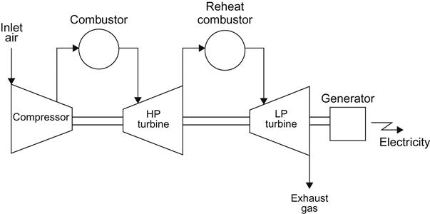
In a reheat gas turbine the hot, high pressure gases from the combustor enter the high pressure spool of the gas turbine where energy is extracted and the temperature and pressure drops. The cooler gases exiting the high pressure spool then enter a second combustor where additional fuel is burnt to raise the temperature of the gases again. These gases then enter the second turbine spool where, because the temperature has been increased, more energy can be extracted than would have been possible at the lower temperature at which they exited the first spool. The gas turbine reheat cycle is shown in Fig. 6.2.
The French company Alstom successfully incorporated this design feature into its heavy duty gas turbines. The design used a higher compression ratio, 30:1, than most other industrial gas turbine designs. The use of reheat allowed the inlet temperature at the first stage of the high pressure power turbine spool to be lower than in comparable turbines without reheat and so permitted less costly materials and cooling designs to be used. The design had significant efficiency advantages when operating in open cycle at part load, a feature that will be increasingly important for future gas turbine power plants. So far no other company has emulated this design for industrial gas turbines.
6.3 Intercooling
If reheat requires the power turbine of a gas turbine to be divided into two spools, intercooling does the same for the compressor. Instead of a single set of stages, the compressor is divided into two sets, or spools. The compressed air from the first spool is then passed through a cooler—the intercooler—before entering the second spool.
The intercooler is a heat exchanger that extracts heat from the compressed air. It can be an air to air heat exchanger where ambient air is the cooling fluid or, more commonly, a water to air heat exchanger that uses cold water to reduce the temperature of the compressed air from the first spool of the compressor. A gas turbine with intercooling of the compressor is shown schematically in Fig. 6.3.

The advantage of intercooling is that it reduces the volume of the compressed air and so reduces the amount of work that the compressor has to do in order to achieve the required pressure at its outlet. This means that it will consume less of the energy produced by the power turbine, leaving more for power generation. It also allows a higher pressure to be achieved with the compressor. The result is an overall increase in engine efficiency.
Other similar strategies include cooling the inlet air with a refrigeration system, or by spraying a mist of water into the intake. Like intercooling, this is effective because it reduces the amount of work the compressor has to do to reach a specified compression ratio. However the addition of water to the air has other effects too, as are discussed below.
Intercooling has been implemented in an aero derivative turbine manufactured by GE called the LMS100. This machine has a six stage low pressure compressor spool. The air exiting this spool is then taken into an off-unit intercooler that can be either air or water cooled. After being cooled the air is returned to the high pressure compressor spool. With intercooling, an overall compression ratio of 42:1 is achieved. The compressed air then enters the combustor where the temperature is raised to 1380°C before entering the first of three power turbine spools. The first, two stage high pressure turbine is used to drive the high pressure compressor spool. This is followed by a two stage intermediate pressure turbine which drives the low pressure compressor. Finally a five stage power turbine drives the generator. The system can generate between 100 and 110 MW depending on the precise configuration and has an efficiency of 46%.
6.4 Mass Injection
A final strategy for increasing the efficiency of a gas turbine is called mass injection. This involves introducing water or steam at some stage during the gas turbine cycle. Steam may be injected into the combustor of a gas turbine where it can also be used to lower the firing temperature and reduce the production of nitrogen oxides. This will at the same time result in an increase in power output. An increase in performance can also be achieved by injecting water into the compressor. The idea was first explored during the early 1970s and Dah Yu Cheng obtained a number of patents covering this type of cycle.
The use of mass injection is a strategy to get around one of the basic efficiency problems in a gas turbine. The high combustion temperature in the combustor, peaking at around 1900°C with natural gas if it is burnt in a stoichiometric amount of air, is too high for the components in the hot gas path. So, in order to reduce the temperature, excess air beyond what is needed for the combustion process is added. Excess air helps reduce the combustion temperature. However, this excess air must be compressed along with the air that will react with the natural gas and this additional compression represents a parasitic load that reduces the overall efficiency of the cycle.
Steam injection into the combustor of a gas turbine helps to cool the combustion gases and as a result less excess air is needed. In addition the steam adds to the mass passing through the gas turbine, increasing its power output. Adding steam in this way, or it other ways discussed below, is a little like combining a steam turbine and a gas turbine in a single cycle. This can be seen as a cheaper alternative to the combined cycle plant discussed below in Chapter 7. However, it is not as efficient as the latter.
The most common form of mass injection is the steam injected gas turbine cycle which is exploited in a number of commercial gas turbine systems. In this type of cycle the waste heat from the exhaust of the gas turbine is used to produce steam and this steam is then injected into the gas turbine, as shown in Fig. 6.4. Steam injection can take place either at the start of the combustor or between the combustor and the power turbine. Injection in the combustor is normally preferred because the steam will cool the combustor.

The addition of steam increases the mass of gas passing into the power turbine. This results in a higher power output from the turbine that would be achieved without steam input. The generation of the steam has an energy cost but this was energy that would have been wasted otherwise. The net result is an increase in efficiency compared to the same turbine without steam injection of between 2% and 4%.
A similar effect can be produced by introducing a fine spray of water into the inlet of the compressor of a gas turbine. This procedure, called inlet fogging, affects the performance of the gas turbine by cooling the inlet air and by an intercooling effect within the compressor, both of which help boost output of the machine.
More complex mass injection cycles are also possible. One of the most explored is the humid air turbine (HAT) cycle, shown in one version in Fig. 6.5. In this cycle the compressor is divided into two spools with an intercooler between them. There is also a recuperator that recovers heat from the turbine exhaust. The recuperator is used to heat the compressed gases just before they enter the combustion chamber, as in a conventional recuperated system. However, the lower grade heat from the recuperator, after it has been used to heat the gases entering the combustor, is also used to heat water. The heat from the intercooler is used for the same purpose. The heated water is used to humidify the compressed air that exits the compressor so that the air which finally enters the combustion chamber is saturated with water. This complex cycle is claimed to have a significantly higher efficiency than a conventional gas turbine but without the cost involved in building a more complex combined cycle plant.

A further refinement of the HAT cycle, called the cascaded HAT cycle introduces a reheat stage, dividing the power turbine into two spools. This variation has a claimed efficiency of up to 55%. Other variants include the injection of water into the compressor stages and water injection at the compressor inlet. Yet another uses solar energy to add heat to the compressed gases before entry into the combustor. All these mass injection cycles release significant amounts of water vapor into the atmosphere and so require large volumes of water available to be able to operate. None of these cycles has yet been converted into a commercial gas turbine system.
6.5 Cogeneration
Cogeneration is another way of improving the efficiency of a gas turbine power plant. In this case the heat from the turbine exhaust, and from any other source in the cycle, can be used to generate either steam or hot water. The high temperature of a gas turbine exhaust makes this an ideal way of producing steam for plant that requires high temperature process heat. If that is not required then hot water can be produced for local space heating and hot water needs, or for a district heating system. An efficiently designed cogeneration system of this type can increase overall efficiency, when heat generation is included along with electricity generation, between 80% and 90%.