
Gas Turbines
Abstract
The most important machine for generating electricity from natural gas is the gas turbine. These engines which were developed primarily as power units for aeroplanes but were adapted virtually since they first appeared for power generation. However, it is only since the late 1980s and the appearance of the modern gas turbine combined cycle power plant that the use of natural gas for power generation has accelerated. The gas turbine has three key components, the compressor, the combustor and the turbine section. Each must be optimized to achieve high efficiency. A high efficiency gas turbine operating in open cycle mode can achieve an efficiency of 46%. The largest industrial gas turbines generally have slightly lower efficiency.
Keywords
Gas turbine; aeroderivative gas turbine; industrial gas turbine; compressor; combustor; power turbine; blade; nozzle
While the technologies discussed in Chapter 3 all offer important ways of using natural gas to produce electricity, it is the gas turbine that has revolutionized the use of natural gas for the power industry. The modern gas turbine was originally developed as an aero engine but was quickly adapted to stationary applications including power generation. However, initial uptake was limited. It took several decades before modern, heavy duty gas turbines evolved and became the dominant type of gas turbine in the power generation market.
Like most power generation technologies, the technological principles upon which the gas turbine is based were first explored during the 19th century. Working machines were first perfected during the early years of the 20th century but it was the recognition of their potential as aviation power units that accelerated the development of the technology. Power generation applications were tested as early as 1939 but the use of gas turbines in the power generation industry only picked up gradually after the Second World War and until the 1980s most gas turbines for power generation were relatively small.
The potential for high efficiency combined cycle plants was fully recognized during the 1980s and this encouraged manufacturers to develop large, heavy duty gas turbines specifically for this market. This led, in turn, to rises in the overall efficiency of such power stations so that in the second decade of the 21st century power plants with overall efficiencies of over 60% are in operation. Gas turbines in simple open cycle configuration can reach 46% efficiency.
4.1 The History of the Gas Turbine
A gas turbine is a device that converts the energy contained in a gas, usually air, into rotary motion. One device of this type is the windmill or wind turbine which converts the energy of moving air, the wind, into rotary motion. While the wind turbine harnesses the energy of free air, a gas turbine is normally driven by a high pressure, often high temperature gas that is constrained within a casing. This allows much greater control of the energy capture process.
The very earliest forerunner of this type of device was built by Hero of Alexander in the 1st century AD.1 It used the reaction of jets of steam from a pair of nozzles on opposite sides of a boiler vessel mounted on a shaft to drive rotation of the vessel about its axis. This use of hot, expanding gas to drive motion is common to both steam and gas turbines. Another forerunner of the gas turbine is the “chimney jack.” This was a simple turbine that was mounted into a chimney so that hot air rising up the chimney caused it to turn. This motion could then be harnessed, for example, to turn meat on a rotating spit.
The first invention containing all the elements of a modern gas turbine was described by the English inventor John Barber in a patent taken out in 1791. This “Method of Rising Inflammable Air for the Purposes of Procuring Motion” contained a compressor, a combustion chamber and a turbine, the key elements of any modern gas turbine. It is not known if the machine was ever built or operated successfully but modern models have been built and do produce motion.
During the 19th century a number of early gas turbines were developed. These all used a compressor to generate a flow of pressurized air and this flow was fed into a turbine in order to drive a shaft and produce mechanical work. In all these machines the compressor was separate from the turbine and while overall efficiency was probably very low, the fact that the compressor was decoupled from the turbine meant that they were always able to produce power to drive machinery.
The first attempt to design what is recognizably a modern gas turbine can be found in a design by the German engineer Franz Stolze, published in 1872. The design used an axial compressor to compress air that was then fed into a combustion chamber with a fuel which was ignited to produce a stream of very hot, high pressure gas. This hot gas was fed into a multistage turbine which rotated, driving a shaft. Crucially, both the compressor and the turbine were mounted on the same shaft, as in a modern turbine. In order for a design of this type to be able to run, the turbine must produce more power than is needed to drive the compressor. Otherwise it cannot operate continuously. The Stolze design was never able to do this because neither turbine nor compressor was efficient enough for continuous operation to be possible. That requires a minimum of around 80% efficiency for each part of the system.
The first gas turbine that was capable of sustained operation was built by Norwegian engineer Aegidius Elling and demonstrated in 1903. The Elling turbine produced power in excess of that needed to drive its components and had a net output of 8 kW which was delivered as compressed air that could drive pneumatic machinery. The design also incorporated water injection into the hot gases between the combustion chamber and the turbine, a process that is used today in some modern gas turbine cycles. The gas turbine inlet temperature was 400°C, low by modern standards. Turbine speed was 20,000 rpm. In 1904, Elling was able to increase the inlet temperature to 500°C and the power output to 33 kW.
There were further developments during the first part of the 20th century. However the next milestones occurred during the 1930s when Swiss company BBC Brown Boveri started to manufacture axial compressors and turbines for supercharged steam generation. At the same time the British engineer Frank Whittle was developing a gas turbine for jet propulsion. His first engine ran in 1937 while in 1939 Brown Boveri installed a gas turbine in a power station for the first time as a generating unit. This marked the birth of the new power generating technology.
4.2 The Gas Turbine Principle
A modern gas turbine has three key components, a compressor, a combustion chamber and a turbine as shown in Fig. 4.1. Air is drawn into the compressor and compressed, then fed into the combustion chamber where fuel is injected continuously, releasing heat which raises both the temperature and the pressure of the air. This high temperature gas stream is then fed into the turbine to produce power. In the standard design the compressor and combustion chamber are mounted on the same shaft and that shaft is also coupled to the generator. The turbine stage of the machine must therefore generate enough shaft power to both turn the compressor and rotate the generator.

The turbine section of a gas turbine is a type of heat engine and so like the steam turbine discussed above in Chapter 3, its energy conversion efficiency is determined by the Carnot Cycle efficiency-limit which depends on the difference between inlet and outlet temperatures. This means that the inlet gas temperature is a key parameter for determining overall efficiency and much of the development of modern gas turbines has been focused on finding materials and techniques that allow ever higher inlet temperatures to be achieved.
The actual cycle upon which a gas turbine operates is called the Brayton Cycle after George Brayton who first conceived it. Its defining feature is that heat is added to the working fluid, air, at constant pressure. At the time of its invention, the Brayton Cycle could not compete with the reciprocating Otto Cycle engine but the development of the gas turbine engine, which turned out to operate on the Brayton Cycle—though this was not immediately recognized—showed that it could be extremely effective.
Brayton’s original engine, which was a development of the work of John Barber, was a type of piston engine with one piston to compress air which then passed into a mixing chamber where fuel was added. This mixture was then ignited as it entered the expansion chamber where it drove another piston. The compression cylinder piston was driven by the expansion chamber piston.2 The gas turbine cycle shares similar compression, combustion and expansion sections, although they operate completely differently.
The early development of gas turbines was aimed at producing jet engines for military use. This work, which built on that of Whittle, carried on through the 1940s, 1950s and 1960s. Aero engine development continues, though today it is as often for commercial as for military aviation applications. A cross-section of a gas turbine jet engine is shown in Fig. 4.2.
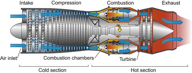
A jet engine takes air in through its front air intake, compresses it, then burns fuel in the compressed air to create a hot high pressure jet. This high pressure air passes through a set of turbine blades where some power is extracted to drive the compressor. The remaining blades reduce the gas pressure and increase the velocity of the air which is expelled from the rear of the turbine. This jet of air creates the thrust that, by Newton’s third law of action and reaction, is used to get the aircraft airborne and keep it there. The turbine may be conceived as a propeller enclosed in a shell instead of a propeller that turns in free air as was more traditional with early aeroplanes. Enclosing the propeller allows the input air speed to be controlled independently of the rate at which the machine moves through the air and this allows the aeroplane to travel faster.
The adaptation of these turbines for mechanical drive and power generation meant redesigning the turbine stages of the gas turbine so that as much energy as possible is captured from the hot, high pressure air that is delivered into the turbine from the combustion chamber. Instead of creating thrust, the energy is delivered to the turbine shaft as mechanical power. These aeroderivative gas turbines proved to be efficient and highly cost effective and they still form a major part of the gas turbine industry today.
Aero engines must be light in order to reduce overall airborne weight. Weight is less of a consideration for stationery and industrial use. This has allowed aeroderivative gas turbines to diverge from their aero engine heritage although many retain close similarities. In the last decades of the 20th century the major gas turbine manufacturers began to adapt the gas turbine even further, building heavy duty gas turbines that were specifically for power generation. The cross-section of a large industrial gas turbine is shown in Fig. 4.3. These units have since become much bigger than their aeroderivative counterparts and design philosophies have also diverged. Even so, aero engine developments, particularly related to design of new materials, quickly find their way into the larger industrial machines.

4.3 A Note About Pressure
The operation of the components in a gas turbine depends on the interaction of these components with high pressure air, an interaction which involves changes in the pressure of the air. There are two different types of pressure that need to be considered when analyzing how these components operate, static pressure and impact, or dynamic pressure. Static pressure is the pressure that a stationary fluid exerts on its surroundings. For example, the air in a balloon exerts a static pressure on the fabric of the balloon. Dynamic pressure on the other hand is the pressure that is created by a moving fluid. The pressure or force exerted by a jet of water is an example of dynamic pressure. When a fluid such as air is moving it will exert both a dynamic and a static pressure. These two together make up the total pressure of the fluid. In the absence of any energy input or loss, the total pressure remains constant. However the balance between static and dynamic pressure can change. This is important for gas turbine operation.
The interaction of the components in a gas turbine with the working fluid, air, affects the balance between the two sorts of pressures. The shape of the air paths within the gas turbine or compressor can convert dynamic pressure into static pressure and vice versa. If a stream of high speed air passes through a duct that diverges so that its cross-sectional area increases, the high speed air will fill the increasing volume. This will decrease its velocity but since there is no energy change taking place, the static pressure must increase in order for the total pressure to remain unchanged.3 A converging duct will have the opposite effect, increasing the velocity of the fluid flowing through it. Both these effects take place in gas turbine compressors and turbines.
The processes that take place in a gas turbine also involve changes in temperature. Compression of a gas leads to an increase in its temperature while expansion leads to a fall in temperature. Heat energy is added both in the compressor, during compression, and in the combustor. The heat energy is then expanded during the energy conversion process within the turbine.
4.4 Compressors
The role of the compressor in a gas turbine is to produce a stream of highly compressed air that can be fed into a combustion chamber where it is mixed with fuel and then ignited. During the compression process the pressure of the air increases, but its velocity as it passes through the machine should not. The compressor is normally mounted onto the same shaft as the turbine and uses some of the power developed by the turbine to carry out its function.
The compressor of a modern gas turbine will typically have 10 to 16 sets of compressor blades and vanes, usually called stages. Each stage will compress the air from the previous stage. The overall compression ratio varies from manufacturer to manufacturer and from turbine to turbine but will typically be between 15:1 and 30:1.
Most gas turbines use axial flow compressors. In such a compressor each stage consists of a set of blades that are attached to the shaft of the compressor and rotate with it, followed by a set of static vanes. The blades in the first stage draw in air and increase its pressure and velocity. This air then passes through the static vanes which by their shape convert the increase in velocity into an increase in pressure. The air then passes to the next stage where further compression takes place, and so on until the air exits the final stage at the required pressure. Compression also increases the air temperature so that the air exiting the compressor is hotter than the air that entered.
The compressor section of the gas turbine also includes inlet guide vanes to ensure that air is drawn into the first stage at the best angle. Finally there are also outlet guide vanes that direct the air into the combustion chamber.
Compressor efficiency is typically around 87%. Overall efficiency is determined by the smoothness of the air flow through the compressor and much of the design effort is to ensure that this is as smooth as possible. Blades and vanes are generally in the shape of aerofoils to maintain smooth flow and prevent turbulence. It is also important to prevent any backwards flow of air as the pressure increases from stage to stage along the compressor. In order to achieve this, the clearance between the tips of the rotating blades and the casing is kept to a minimum and the static vanes have seals to prevent backward leakage. The precise shape and angle of blades and static vanes depends on the rotational speed of the compressor so the machine needs to operate at its design speed in order to achieve the highest efficiency.
4.5 Combustion Chambers
The combustion chamber of a gas turbine is where the energy that drives the whole system is added. The combustion chamber of a modern turbine typically consists of a cylinder with a second smaller cylinder called the liner inside it. A fuel air mixture passes into the mouth of the liner and additional air may pass around the outside of it, between the liner and the outer cylinder to keep the liner cool. This air is then introduced through holes and slots along the liner.
In most modern gas turbine combustors the air is premixed with fuel before it is injected into the combustion chamber through a set of nozzles. The shape and direction of the nozzles and baffles in the combustor are carefully designed to ensure both even mixing and a stable flame within the combustor. The fuel air mixture ignites in the combustion zone, releasing energy as heat. The temperature in the combustion zone flame can reach over 1900°C, far higher than most materials can withstand. In order to control this some of the air from the compressor may be used to cool the walls of the combustion chamber liner. This will also dilute the very hot combustion gases to reduce their temperature.
The air flow through all parts of the combustion chamber must be carefully managed to avoid flame instability and turbulence which will lead to energy loss. The aim is to produce a smooth flow of air, even though the addition of heat energy will raise its temperature and increase the total pressure.
The addition of air into the combustion chamber is also carefully managed in order to control the production of NOx during the combustion process. The high temperatures within the combustion zone will lead to ready production of nitrogen oxides from the reaction between oxygen and nitrogen from air. This can be controlled by maintaining reducing conditions. By keeping the amount of oxygen low compared to the quantity required to burn all the fuel, NOx production can be minimized. With this type of staged combustion further air is introduced into the latter stages of the combustion zone in order to allow the combustion reaction to continue to completion. However many modern combustors rely on careful mixing of the fuel and air in stoichiometric proportions before the mixture enters the combustor to keep NOx production under control.
After the combustion process is complete the hot gases pass into the final stage of the combustion chamber which is called the transition section. This is a convergent duct that will convert static pressure into dynamic pressure, increasing the velocity of the hot gases before delivering them into the turbine section.
The type and number of combustion chambers in a gas turbine will vary from manufacturer to manufacturer and from turbine to turbine. Many larger turbine designs use a set of annular combustion chambers that surround the turbine shaft between compressor and turbine. Others take air from the compressor outside the body of the turbine to one or more combustion chambers and then return the gases to the turbine.
At least one manufacturer of heavy industrial gas turbines also uses multiple sets of gas turbines and combustion chambers. This design splits the turbine section of the gas turbine into two. Hot air from the first set of combustion chambers enters the first turbine section where energy is extracted by the turbine blades, then the air enters a second set of combustion chambers where more fuel is burnt and more energy added before being fed into a second turbine section. This type of design, called a reheat turbine, is often used in large steam turbines for power generation but is much less common in gas turbines.
4.6 Turbines
The final part of the gas turbine is the turbine section. This is where the energy from the fuel is converted into a form of mechanical energy, the rotation of the turbine shaft generating a torque. All gas turbines except for some very small machines use axial flow turbine sections. As with the compressor, the axial flow turbine will consist of a number of stages, each stage including a set of stationary vanes, usually called nozzles and a set of rotating blades that are attached to the turbine shaft.
There are two major types of turbine/blade design that can be applied to a gas turbine, each defined by the way it extracts energy from a fluid. The two are called reaction turbines and impulse turbines. One way of understanding the difference is to observe that reaction turbines exploit the static pressure in a fluid whereas impulse turbines exploit the dynamic pressure. This means that as fluid passes through a reaction turbine the static pressure drops but the fluid velocity which defines its dynamic pressure remains relatively constant. In contrast when a fluid passes through an impulse turbine stage the velocity drops while the static pressure remains constant. The stages of a modern axial gas turbine will generally combine the two, extracting part of their energy from the static pressure and partly from the dynamic pressure. It is common for the first stages to be predominantly impulse type while the latter stages are more reaction type. However all stages usually exploit both.
The order of the stationary vanes and rotating blades in the turbine is the reverse of the compressor. The high pressure, high temperatures gas from the combustor meets a stage’s vanes first and then is directed to its blades. The vanes form convergent ducts which turn static pressure into dynamic pressure, increasing the speed of the air passing through them. This dynamic pressure is then used to drive round the rotating blades. As in the compressor, both vanes and blades are shaped like aerofoils in order to ensure the smooth flow of air through the complete turbine. Each stage extracts a portion of the energy contained in the air.
In a simple gas turbine the compressor and the turbine blades are all on a single shaft. However there are more complex arrangements. In some machines there are two concentric shafts. One of these carries the compressor blades and the first one or two stages of turbine blades. The later turbine stages are attached to a second shaft that drive the generator to produce electrical power. In some aeroderivative gas turbines this is taken further still and the compressor stages are divided too. The low pressure compressor blades are then mounted onto the same shaft as low (or medium) pressure turbine stages while the high pressure compressor stages are on the same shaft as the high pressure turbine stages.
The efficiency of a gas turbine will depend on the temperature drop across the stages. In order to achieve high efficiency the turbine stage inlet temperature must be very high. In some modern gas turbines the inlet temperature can reach 1600°C. It requires very special materials and design techniques to design turbine components that can withstand this temperature.
The efficiency of a gas turbine will depend not only on the inlet gas temperature but also on the temperature of the gas as it leaves the final stage of the gas turbine. The exhaust gas from a simple cycle gas turbine, that is one not in a combined cycle configuration, needs to be a cool as possible in order to achieve maximum efficiency. However in a combined cycle power plant a part of the energy is captured in a steam generator that exploits waste heat in the gas turbine exhaust. The temperature of the exhaust gas exiting a turbine in this type of plant will be much higher. The temperature at the exhaust of a high efficiency aeroderivative gas turbine will probably be in the 400°C to 500°C range. While this is relatively high it still enables efficiency of up to 46% for the best machines. Other small industrial turbines will have efficiencies of up to 42%. Conversely large industrial gas turbines designed for combined cycle operation may have exhaust gas temperatures above 600°C. Efficiencies may be as low as 38% but will typically be up to 42%.