
Scientific Workflow Management System for Clouds
Maria A. Rodriguez; Rajkumar Buyya Cloud Computing and Distributed Systems (CLOUDS) Laboratory, School of Computing and Information Systems, The University of Melbourne, Australia
Abstract
Infrastructure-as-a-Service clouds offer access to a scalable virtualized infrastructure on a pay-per-use basis. This is greatly beneficial for the deployment of scientific workflows, and as a result considerable effort is being made to develop and update existing workflow management systems to support the cloud resource model. The majority of existing systems are designed to work with traditional distributed platforms such as grids and clusters in which the resources are limited and readily-available. In contrast, clouds offer access to elastic and abundant resources that can be provisioned and deprovisioned on-demand. In this chapter, we present our efforts to extend an existing workflow system, the Cloudbus WMS, to enable the deployment of scientific applications in cloud computing environments. We present a case study to demonstrate the added functionality and evaluate the performance and cost of a well-known astronomy application on Microsoft Azure.
Keywords
Scientific workflow management system; IaaS cloud; Auto-scaling; Scheduling; Resource provisioning
18.1 Introduction
Workflows are a commonly used application model in computational science. They describe a series of computations that enable the analysis of data in a structured and distributed manner and are commonly expressed as a set of tasks and a set of dependencies between them. These applications offer an efficient way of processing and extracting knowledge from the ever-growing data produced by increasingly powerful tools such as telescopes, particle accelerators, and gravitational wave detectors and have been successfully used to make significant scientific advances in various fields such as biology, physics, medicine, and astronomy [1].
Scientific workflows are often data- and resource-intensive applications and require a distributed platform in order for meaningful results to be obtained in a reasonable amount of time. Their deployment is managed by Workflow Management Systems (WMS) which are responsible for transparently orchestrating the execution of the workflow tasks in a set of distributed compute resources while ensuring the dependencies are preserved. A high-level overview of this process is shown in Fig. 18.1. In general, WMSs provide essential functionality to enable the execution of workflows such as data management and provenance, task scheduling, resource provisioning, and fault tolerance among others.

The latest distributed computing paradigm, cloud computing, offers several advantages for the deployment of these applications. In particular, Infrastructure-as-a-Service (IaaS) clouds offer WMSs an easily accessible, flexible, and scalable infrastructure by leasing virtualized compute resources, or Virtual Machines (VMs). This allows workflows to be easily packaged and deployed and more importantly, enables WMSs to access a virtually infinite pool of heterogeneous VMs that can be elastically acquired and released and are charged on a pay-per-use basis.
In this way, WMSs can use cloud resources opportunistically based on the number and type of tasks that need to be processed at a given point in time. This is a convenient feature as it is common for the task parallelism of scientific workflows to significantly change throughout their execution. The resource pool can be scaled out and in to adjust the number of resources as the execution of the workflow progresses. This facilitates the fulfilment of the quality-of-service (QoS) requirements by allowing the WMS to fine-tune performance while ensuring the available resources are efficiently used.
In this chapter we present an existing WMS and detail its extension to support the cloud computing paradigm. Firstly, we review the concept of scientific workflow and the infrastructure services offered by clouds as well as existing management solutions for workflow applications. Next, we introduce common functionalities of WMSs designed for cloud environments as well as a general architecture and its components. We then introduce the Cloudbus WMS [2] and detail our implementation of cloud-enabling components to support the dynamic provisioning and deprovisioning of VMs. Finally, with the aim of demonstrating the added functionality, we present a case study on the use of cloud services for a well-known scientific workflow from the astronomy domain.
18.2 Background
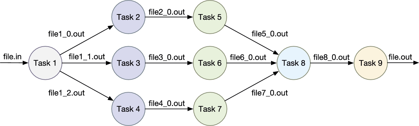
The concept of workflow has its roots in commercial enterprises as a business process modeling tool. These business workflows aim to automate and optimize the processes of an organization, seen as an ordered sequence of activities, and are a mature research area [3] lead by the Workflow Management Coalition1 (WfMC), founded in 1993. This notion of workflow has extended to the scientific community where scientific workflows are used to support large-scale, complex scientific processes. They are designed to conduct experiments and prove scientific hypotheses by managing, analyzing, simulating, and visualizing scientific data [4]. In science, it is common for these applications to be composed of a set of computational tasks and a set of data or control dependencies between the tasks. A sample workflow application can be seen in Fig. 18.2.
Extensive research has been done on the use of scientific workflow systems, particularly in shared infrastructure environments such as grids and dedicated clusters. An example is the Askalon [5] system developed at the University of Innsbruck, Austria. It facilitates the development and optimization of workflows on distributed infrastructures and supports the execution of workflows expressed in an XML-based language called AGWL that enables the specification of looping structures, conditional statements, and Directed Acyclic Graph (DAG) constructs. Another system is Kepler [6], it offers services to design, execute, and share scientific workflows and supports various models of computations such as superscalar and streaming workflows. Taverna [7] is a suite of tools used to design and execute scientific workflows and aid in silico experimentation. The system is capable of interacting with various types of services including web services, data warehouses, and grid services. Finally, Pegasus [8] WMS supports the deployment of workflows in different environments and has the ability to execute workflows expressed as DAGs, manage their data, monitor their execution, and handle failures. A comprehensive taxonomy and survey of these systems is presented by Yu and Buyya [9]; it provides an understanding of existing works from different perspectives such as scheduling, fault management, and data movement.
With the advent of cloud computing, researchers are now focusing on extending existing workflow systems to support the deployment of scientific applications in cloud environments, particularly in IaaS clouds. For instance, the above mentioned products, although initially developed for grids and clusters, have now been enhanced to work with IaaS resources. That is, they are capable of interacting with IaaS vendors that offer VMs for lease with a predefined CPU, memory, storage, and bandwidth capacity. Different resource bundles (i.e., VM types) are available at varying prices and are generally charged per time frame, or billing period. While VMs deliver the compute power, IaaS clouds also offer storage and networking services, providing all the necessary infrastructure for the execution of workflow applications.
WMSs and their users can benefit in different ways from using IaaS resources. As already mentioned, clouds eliminate the need to own any physical resources and users can easily access a flexible and scalable infrastructure on-demand. This not only leads to WMSs being able to customize the type and number of resources used at any point in time but is also beneficial in economical terms. For instance, Deelman et al. [10] studied the cost of running scientific workflows in the cloud. Specifically, they studied the trade-off between cost and performance under different execution and resource provisioning plans as well as storage and networking fees on Amazon AWS. Their findings support the fact that clouds are a cost-effective solution for scientific applications.
Another benefit derives from the fact that scientific workflows are generally legacy applications that contain heterogeneous software components. Virtualization allows for the execution environment of these components to be easily customized. The operating system, software packages, directory structures, and input data files, among others, can all be tailored for a specific component and stored as a VM image. This image can then be easily used to deploy VMs capable of executing the software component they were designed for. Another advantage of using VM images for the deployment of workflow tasks is the fact that they enable scientific validation by supporting experiment reproducibility. Images can be stored and redeployed whenever an experiment needs to be reproduced as they enable the creation of the same exact environment used in previous experiments. The Cloudbus WMS, presented in the sections to follow, is our initiative towards leveraging the aforementioned benefits.
18.3 Workflow Management Systems for Clouds
We will begin by introducing a general architectural model for cloud WMSs. In general, a WMS enables the creation, monitoring and execution of scientific workflows and has the capability of transparently managing tasks and data by hiding the orchestration and integration details among the distributed resources [2]. A reference architecture is shown in Fig. 18.3. The depicted components are common to most cloud WMS implementations, however, not all of them are required to have a fully functional system.

User interface. The user interface allows for users to create, edit, submit, and monitor their applications.
Workflow engine. The workflow engine is the core of the system and is responsible for managing the actual execution of the workflow. The parser module within the engine interprets a workflow depicted in a high level language such as XML and creates the corresponding internal workflow representation such as task and data objects. The scheduler and resource provisioning modules work together in planning the execution of the workflow. The resource provisioning module is responsible for selecting and provisioning the cloud resources and the scheduling component applies specific policies that map tasks to available resources, both processes are based on the QoS requirements and scheduling objectives. The performance prediction and runtime estimation module use historical data, data provenance, or time series prediction models, among other methods, to estimate the performance of cloud resources and the amount of time tasks will take to execute on different VMs. This data is used by the resource provisioning and scheduling modules to make accurate and efficient decisions regarding the allocation of tasks. The data management component of the workflow engine manages the movement, placement, and storage of data as required for the workflow execution. Finally, the task dispatcher has the responsibility of interacting with the cloud APIs to dispatch tasks ready for execution onto the available VMs.
Administration and monitoring tools. The administration and monitoring tools of the WMS architecture include modules that enable the dynamic and continuous monitoring of workflow tasks and resource performance as well as the management of leased resources, such as VMs. The data collected by these tools can be used by fault tolerance mechanisms or can be stored in a historical database and used by performance prediction methods, for example.
Cloud information services. Another component of the architecture is the cloud information services. This component provides the workflow engine with information about different cloud providers, the resources they offer including their characteristics and prices, location, and any other information required by the engine to make the resource selection and mapping decisions.
Cloud provider APIs. These APIs enable the integration of applications with cloud services. For the scheduling problem described in this chapter, they enable the on-demand provisioning and deprovisioning of VMs, the monitoring of resource usage within a specific VM, access to storage services to save and retrieve data, transferring data in or out of their facilities, and configuring security and network settings, among others. The majority of IaaS APIs are exposed as REST (Representational State Transfer) and SOAP (Simple Object Access Protocol) services, but protocols such as XML-RPC and Javascript are also used. For instance, CloudSigma, Rackspace, Windows Azure, and Amazon EC2 all offer REST-based APIs. As opposed to providing services for a specific platform, other solutions such as Apache JClouds2 aim to create a cross-platform cloud environment by providing and API to access services from different cloud providers in a transparent manner. Cross-platform interfaces have the advantage of allowing applications to access services from multiple providers without having to rewrite any code, but may have less functionality or other limitations when compared to vendor-specific solutions.
18.4 Cloudbus Workflow Management System
The Cloudbus WMS was developed at the CLOUDS Laboratory in the University of Melbourne, Australia. It allows scientist to express their applications as workflows and execute them on distributed resources by transparently managing the computational processes and data. Its architecture consists of a subset of the components depicted in Fig. 18.3 and is presented in Fig. 18.4.

The Workflow Portal is the entry point to the system. It provides a web-based user interface for scientists to create, edit, submit, and monitor their applications. It provides access to a Workflow Deployment page that allows users to upload any necessary data and configuration input files needed to run a workflow. A Workflow Editor is also embedded in this component and it provides a GUI that enables users to create or modify a workflow using drag and drop facilities. The workflow is modeled as a DAG with nodes and links that represent tasks and dependencies between tasks. The editor converts the graphical model designed by the users into an XML based workflow language called xWFL which is the format understood by the underlying workflow engine.
The Workflow Monitor Interface is also accessed through the portal and it provides a GUI to the Workflow Monitor module which is part of the Monitoring Services component. It allows users to observe the execution progress of multiple workflows and to view the final output of an application. Users can monitor the status of every task in a specific workflow, for instance, tasks can be on a ready, executing, stage in, or completed status. Additionally, users have access to information such as the host in which a task is running, the number of jobs being executed, and the failure history of each task. The Workflow Monitor relies on the information produced by the Workflow Engine and the interaction between these two components takes place via an event mechanism using tuple spaces. In broad terms, whenever the state of a task changes, the monitor is notified and as a response to the event, it retrieves the new state and any relevant task metadata from a central database. Finally, the portal offers users access to a Resource Monitor Interface which displays the information of all the current available computing resources. The Resource Monitor module in the Monitoring Services component is responsible for the collection of this information.
The Workflow Engine is the core of the Cloudbus workflow management system; its main responsibilities include scheduling, dispatching, monitoring, and managing the execution of tasks on remote resources. As shown in Fig. 18.4, the workflow engine has four main subsystems: workflow language parser, scheduler, task dispatcher, and data manager.
The workflow portal or any other client application submits a workflow for execution to the engine. The submitted workflow must be specified in the XML-based language, xWFL. This language enables users to define all the characteristics of a workflow such as tasks and their dependencies among others. Aside from the xWFL file, the engine also requires a service and a credential XML-based description files. The service file describes the resources available for processing tasks while the credentials one defines the security credentials needed to access these resources. The existence of these two files demonstrates the type of distributed platforms the engine was originally designed to work with, platforms where the resources are readily available and their type and number remains static throughout the execution of the workflow. Once the system is upgraded to support clouds, the use of these files will be obsolete as resources will be created and destroyed dynamically.
The xWFL file is then processed and interpreted by a subsystem called the workflow language parser. This subsystem creates objects representing tasks, parameters, data constraints and conditions based on the information contained on the XML file. From this point, these objects will constitute the base of the workflow engine as they are the ones containing all the information regarding the workflow that needs to be executed. Once this information is available, the workflow is scheduled and its tasks are mapped onto resources based on a specific scheduling policy. Next, the engine uses the Cloudbus Broker as a task dispatcher.
The Cloudbus Broker [11] provides a set of services that enable the interaction of the workflow engine with remote resources. It mediates access to the distributed resources by discovering them, deploying and monitoring tasks on specific resources, accessing the required data during task execution and consolidating results. An additional component that aids in the execution of the workflow is the data movement service which enables the transfer of data between the engine and remote resources based on protocols such as FTP and GridFTP.
The workflow engine has a decentralized scheduling system that supports just-in-time planning and allows resource allocation to be determined at runtime. Each task has its own scheduler called Task Manager (TM). The TM may implement any scheduling heuristic and is responsible for managing the task processing, resource selection and negotiation, task dispatching and failure handling. At the same time, a Workflow Coordinator (WCO) is responsible for managing the lifetime of every TM as well as the overall workflow execution.
Fig. 18.5 shows the interaction between the different components involved in the scheduling process. The WCO creates and starts a TM based on the task's dependencies and any other specific scheduling heuristic being used. Each TM has a task monitor that continuously checks the status of the remote task and a pool of available resources to which the task can be assigned. The communication between the WCO and the TMs takes place via events registered in a central event service.

Each TM is independent and may have its own scheduling policy, this means that several task managers may run in parallel. Additionally, the behavior of a TM can be influenced by the status of other task managers. For instance, a task manager may need to put its task execution on hold until its parent task finishes running in order for the required input data to be available. For this reason, TMs need to interact with each other just as the WCO needs to interact with every TM; once again this is achieved through events using a tuple space environment.
18.5 Cloud-Based Extensions to the Workflow Engine
Several extensions and changes were made to the workflow engine component of the Cloudbus WMS in order to support the execution of workflows in IaaS clouds. These extensions allow for scheduling algorithms and resource provisioning strategies to leverage the elastic and on-demand nature of cloud resources, in particular of VMs. The overall architecture of the system and the interaction between the main components remains the same, the extended architecture is shown in Fig. 18.6, where the shaded components are the newly included ones. Each of these components is explained next and a class diagram depicting their implementation is presented in Fig. 18.7.

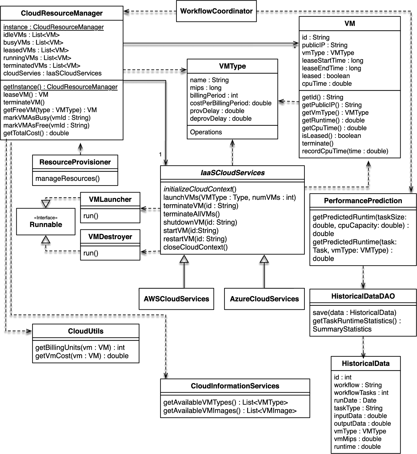
VM lifecycle manager. A module providing an interface to access VM lifecycle management services offered by IaaS providers. These include leasing, shutting down, restarting, and terminating VMs. Access to a provider's VM management API is done using Apache JClouds,3 a Java-based multicloud toolkit. It is an open source library that provides portable abstractions for cloud-specific features. It currently supports 30 providers and cloud software stacks such as OpenStack, Amazon, Google, Rackspace, and Azure. The class diagram in Fig. 18.7 shows the methods and IaaS providers currently supported by this module.
The realization of this module also included eliminating the need of having a set of compute services defined in an XML file previous to the execution to the workflow.
Cloud resource manager. An entity responsible of managing the cloud resources used by the engine. It maintains information on the VMs leased from an IaaS provider. Its responsibilities include keeping track of leased, busy, and idle VMs, as well as recording data regarding the lease of VMs such as their lease start and end times.
The following are examples of data that can be accessed through the Cloud Resource Manager:
• Leased VMs: a list of all the VMs that have been leased throughout the lifecycle of the workflow execution.
• Terminated VMs: a list of all the VMs that have been terminated throughout the lifecycle of the workflow execution.
• Active VMs: a list of VMs that are currently leased and active.
• Busy VMs: a list of all VMs that are active and busy with the execution of one or more tasks.
• Idle VMs: a list of all VMs that are active and idle.
Resource provisioning. An entity responsible of making resource provisioning decisions based on the scheduling objectives and QoS requirements. A basic provisioning strategy was implemented. It monitors the leased VMs every PROV_POLLING_TIME. The value for this polling interval is a configurable parameter that can be defined via a properties file. The provisioner then makes the decision to shut VMs down whenever they are idle and approaching their next billing cycle. It does so by considering the time it takes for VMs to be deprovisioned, the time remaining until the VM reaches the next billing cycle, and the time when the next provisioning cycle will occur. If the deprovisioning delay is larger then the time remaining until the next billing cycle then there is no benefit on shutting down the VM as incurring in a new billing cycle is inevitable. Otherwise, the algorithm decides whether the VM can be left idle and be shutdown on later provisioning cycles without incurring in an additional billing period or if the VM should be deprovisioned in the current cycle to avoid incurring in additional costs. An overview of this strategy is depicted in Algorithm 1. The design provides the flexibility to plug-in different resource provisioning strategies without the need of modifying any other module. For instance, a provisioning strategy that not only decides when to shut-down VMs but also when to lease them based on a utilization metric could also be easily implemented.

Performance prediction and runtime estimation. Two different performance prediction strategies where implemented into a newly created Performance Prediction and Runtime Estimation Module. The first one is a straightforward strategy that allows for the runtime of tasks to be estimated using a measure of the size of a task and the CPU performance of the VM. For this purpose, the xWFL language as well as the existing parser were extended so that the definition of a task includes an optional element indicating its size. In practice, this size can be either the number of instructions (MI), the number of floating point operations (FLOP), or the time complexity of the tasks among others. Additionally, the definition of compute service within the engine was extended to include an optional property indicating a measure of the resource's CPU capacity. For this purpose the schema and parsers of the XML-based service file were modified to include the new property as was the ComputeService class.
The second strategy is based on the analysis of historical task runtime data. For this purpose, task runtimes are recorded on a historical database which can be later used to estimate the runtime of tasks on particular VM types using statistical tools. The data recorded for each task executed by the engine are depicted in Table 18.1. The current strategy calculates the 95% confidence interval of a task runtime given the task name or type, the workflow it belongs to, the number of tasks in the workflow, the amount of input and output data generated by the task, and the name of the VM type for which the prediction is being made for.
Table 18.1
Contents of the database table recording historical runtime data of tasks
| Property | Description |
| Workflow | Name of the workflow application |
| Number of Tasks | Total number of tasks in the workflow |
| Run Date | Date the workflow was deployed |
| Algorithm | Name of the scheduling algorithm managing the workflow execution |
| Task Type | Name or type of the workflow task for which the runtime is being recorded |
| Transferred Input Data | Amount of input data transferred to the task's VM |
| Transferred Output Data | Amount of output data transferred out of the task's VM |
| VM Type | Name of the VM type used to run the task |
| VM CPU Capacity | CPU capacity of the VM type |
| VM Memory | Memory available for the VM type |
| VM Bandwidth | Bandwidth of the VM type |
| Task Runtime | Time taken to complete the task's execution (including input transfer, computations, and output transfer) |
In the future, different prediction algorithms can be seamlessly implemented into this module and used by scheduling algorithms to guide their decisions.
Cloud information services. Through the cloud providers APIs, this module enables the workflow engine to query information regarding the types of services offered by a given provider. Specifically, the implementation leveraged the JClouds API to query the types of VMs available from a given provider as well as the VM images available for use for a given user.
DAX to XWFL. The DAX4 format is a description of an abstract DAG workflow in XML that is used as the primary input into the Pegasus WMS [8], a tool developed at the Information Sciences Institute (ISI), University of Southern California. The extensive research done by this organization in workflows as well as their collaboration with the scientific community makes of the DAX format a popular and commonly used one. For instance, the Pegasus Project5 has developed a tool in conjunction with the NASA/IPAC project that generates the specification of different Montage workflows in a DAX format. Hence, to take advantage of the existence of these tools as well as workflows described in the DAX format, a DAX-to-xWFL tool was developed as part of this thesis. In this way, the Cloudbus WMS now has the ability to interpret workflows expressed in the DAX format.
Scheduler extension. The existing Scheduler component has been modified to allow the workflow coordinator to have the ability to make scheduling decisions in terms of task to resource mappings. The previous version of the scheduler limited the responsibilities of the coordinator to enforcing the dependency requirements of the workflow. That is, it was responsible for monitoring the status of tasks and releasing those ready for execution by launching their task manager, entity which was then responsible for deciding the resource where the task would be executed. The extended version allows for the workflow coordinator to make all of the scheduling and resource provisioning decisions if required based on its global view of the workflow. Additionally, the WRPS [12] algorithm, which will be introduced in the following section, was implemented and integrated into the workflow coordinator.
18.6 Performance Evaluation
This section details the deployment of the Montage application on the Cloudbus WMS. The workflow was scheduled using the WRPS algorithm and Microsoft Azure resources that were dynamically provisioned using the cloud-enabled version of the Cloudbus WMS.
18.6.1 WRPS
WRPS is a resource provisioning and scheduling algorithm for scientific workflows in clouds capable of generating high quality schedules. It has as objectives minimizing the overall cost of using the infrastructure while meeting a user-defined deadline. The algorithm is dynamic to a certain extent to respond to unexpected delays and environmental dynamics common in cloud computing. It also has a static component that allows it to find the optimal schedule for a group of workflow tasks, consequently improving the quality of the schedules it generates. This is done by reducing the workflow into bags of homogeneous tasks and pipelines that share a deadline. The scheduling of these bags is then modeled as a variation of the unbounded knapsack problem which is solved in pseudo-polynomial time using dynamic programming. WRPS considers abundant, heterogeneous, and elastic resources and its provisioning policy results in the VM pool being dynamically scaled in and out throughout the execution of the workflow. For more details, we refer readers to the paper written by Rodriguez and Buyya [12].
18.6.2 Montage
The Montage application is designed to compute mosaics of the sky based on a set of input images. These input images are taken from image archives such as the Two Micron All Sky Survey (2MASS),6 the Sloan Digital Sky Survey (SDSS),7 and the Digitised Sky Surveys at the Space Telescope Science Institute.8 They are first reprojected to the coordinate space of the output mosaic, the background of these reprojected images is then rectified, and finally they are merged together to create the final output mosaic [10].
Fig. 18.8 depicts the structure of the Montage workflow as well as the different computational tasks it performs. The size of the workflow depends on the number of input images used and its structure changes to reflect an increase in the number of inputs, which results in an increase in the number of tasks. For this particular workflow, same-level tasks are of the same type, that is, they perform the same computations but on different sets of data.

The mProjectPP tasks are at the top level of the workflow and hence are the first ones to be executed. They process Flexible Image Transport System (FITS) input images by reprojecting them. There is one mProjectPP task for every FITS input image. In the next level are the mDiffFit tasks. They are responsible for computing the difference between each pair of overlapping images and as a result, their number is determined by the number of overlapping input images. Next is the mConcatFit task, it takes all of the different images as input and fits them using a least squares algorithm. This is a compute-intensive task as a result of its data aggregation nature. The next task is mBgModel which determines a background correction to be made to all the images. This correction is the applied to each individual image by the mBackground tasks in the next level of the workflow. Then, the mImgTbl task aggregates metadata from all the images and is followed by the mAdd job. This task is the most computationally intensive and is responsible for the actual aggregation of the images and the creation of the final mosaic. Finally, the size of the final mosaic is reduced by the mShrink task and the output converted to JPEG format by the last workflow task, mJPEG [13].
For this case study, a Montage workflow constructing a 0.5 degree mosaic of the sky was used. This particular instance of the workflow consists of 143 tasks, their type, number, and level are depicted in Table 18.2.
Table 18.2
Tasks in a 0.5 degree Montage workflow
| Task | Level | Count | Mean runtime (s) | Mean input (MB) | Mean output (MB) |
| mProjectPP | 1 | 32 | 35.94 | 1.66 | 8.30 |
| mDiffFit | 2 | 73 | 31.72 | 16.6 | 1.02 |
| mConcatFit | 3 | 1 | 82.99 | 0.02 | 0.01 |
| mBgModel | 4 | 1 | 43.57 | 0.02 | 0.001 |
| mBackground | 5 | 32 | 30.43 | 8.31 | 8.30 |
| mImgTbl | 6 | 1 | 93.92 | 129.28 | 0.009 |
| mAdd | 7 | 1 | 241.50 | 265.79 | 51.73 |
| mShrink | 8 | 1 | 46.43 | 25.86 | 6.47 |
| mJPEG | 9 | 1 | 88.54 | 6.47 | 0.20 |

The following are the specific characteristics of the Montage workflow used in this case study:
• Survey, 2mass
• Band, j
• Center, M17
• Width, 0.5
• Height, 0.5
18.6.3 Setup of Experimental Infrastructure
There are three types of components involved in the execution of a workflow using the Cloudbus WMS. Each of these is deployed on its own compute resource or node. The first component is the actual workflow engine, or master node, which is responsible for orchestrating the execution of tasks on worker nodes. The lifecycle of these worker nodes is managed by the engine and they contain the actual routines invoked by the workflow tasks. Finally, the storage node acts as a central file repository where worker nodes retrieve their input data from and store their output data to. Fig. 18.9 depicts this deployment.

For the experiments performed in this chapter, the VM configuration and location used for each of these components is as follows:
• Master node: Ubuntu 14.4 LTS virtual machine running locally on a MacBook Pro with a 2.9 GHz Intel Core i7 processor and 8 GB RAM. The virtual machine was launched using Virtual Box and had a memory of 2.2 GB and 125.6 GB disk.
• Storage node: Basic A2 Microsoft Azure virtual machine (2 cores, 3.5 GB RAM) with Ubuntu 14.4 LTS installed deployed on the US East region.
• Worker nodes: Dynamically provisioned on Microsoft Azure's US East region using a custom VM image with Montage installed (see Section 18.6.4). The types of VMs where worker nodes could be deployed are depicted in Table 18.3. The A-series are general purpose compute instances while the D-series VMs feature solid state drives (SSDs) and have 60% faster processors than the A-series.
Table 18.3
Types of VMs used to deploy a 0.5 degree Montage workflow
| VM name | Cores | RAM (GB) | Disk Size (GB) | Price per minute ($) |
| A0 (extrasmall) | 1 | 0.75 | 20 | 0.000425 |
| A1 (small) | 2 | 1.75 | 70 | 0.001275 |
| A2 (medium) | 2 | 3.5 | 135 | 0.002548 |
| D1 | 1 | 3.5 | 50 | 0.001635 |
| D2 | 2 | 7 | 100 | 0.003270 |
| D11 | 2 | 14 | 100 | 0.004140 |

18.6.4 Montage Setup
This section describes how the Montage routines were setup in the worker nodes VM image. It also explains how the input image files were obtained and how the workflow description XML file was generated.
The Pegasus Project has developed various tools that aid in the deployment of Montage workflows in distributed environments. The installation of Montage on the worker VM image as well as the generation of an XML file describing the workflow were done using these tools.
The first step was to download and install the Montage application, which includes the routines (mProjectPP, mDiffFit, mConcatFit, mBgModel, mBackground, mImgTbl, mAdd, mShrink, and mJPEG) corresponding to each workflow task. For this case study, version 3.3 was installed on a VM running Ubuntu 14.4 LTS. In addition to the task routines, the installation of Montage also includes tools used to generate the DAG XML file and download the input image files. Namely, the mDAG and mArchiveExec tools.
The mDAG command generates a DAX XML file containing the description of the workflow in terms of the input files it uses, the tasks, the data dependencies, and the output files produced. This DAX file was then transformed to a xWFL-based one by using the DAX to XWFL tool.
The mArchiveExec command was used to download the input images which were placed in the storage node so that they could be accessed by worker nodes when required.
18.6.5 Results
This section presents the results obtained after executing the 0.5 degree Montage workflow on the Cloudbus WMS under seven different deadlines.
Fig. 18.10A presents the results in terms of the makespan to deadline ratio obtained. The makespan of a workflow is defined as the time it takes for the workflow execution to complete. Ratio values greater than one indicate a makespan larger than the deadline, values equal to one a makespan equal to the deadline, and values smaller than one a makespan smaller than the deadline. Fig. 18.10B depicts the actual makespan values obtained for each deadline. The results presented are the average obtained after running the experiments for each deadline 10 times.

The first deadline of 1500 s is too strict for the workflow execution to be completed on time. On average, it takes approximately 1520 s for the workflow to complete, leading to a ratio of 1.01. This difference between makespan and deadline however is marginal and a 20 s difference is unlikely to have a significant impact on either cost or the usability of the obtained workflow results. The choice of VMs for each deadline interval are presented in Table 18.4. The fact that all of the VMs leased for this deadline interval are of the most powerful VM type (D11), reflects the urgency of the algorithm to complete the workflow execution as fast as possible. The decision to limit the number of VMs to 9 is a direct result of the length of VM provisioning delays. The algorithm recognizes that in some cases it is faster and more efficient to reuse existing VMs rather than leasing new ones.
Table 18.4
Number of VMs per type leased for the deployment of a 0.5 degree Montage workflow with different deadlines
| Deadline (s) | A0 | A1 | A2 | D1 | D2 | D11 |
| 1500 | – | – | – | – | – | 9 |
| 1800 | – | – | – | – | 7 | 2 |
| 2100 | – | 13 | – | 5 | – | – |
| 2400 | 17 | 2 | – | 1 | – | – |
| 2700 | 17 | 2 | – | – | – | – |
| 3000 | 17 | – | – | 2 | – | – |
| 3300 | 18 | – | – | – | – | – |

All of the remaining ratios for the deadlines ranging from 1800 to 3300 s are under one. Clearly, 1800 s is sufficient for the execution of the workflow to complete. This is achieved by leasing 7 D2 VMs and 2 D11 ones. Once again, the deadline is too strict to lease a larger number of VMs but relaxed enough to not have to lease them all of the most powerful type.
As the deadlines becomes more relaxed, WRPS decides it is more efficient to lease a larger number of VMs of less powerful and cheaper types. For a deadline of 2100 s, 13 A1 (small) and 5 D1 VMs are sufficient for the workflow execution to finish well under the deadline with an average ratio of 0.85. From this deadline onwards, the algorithm can finish the workflow execution on time with minimum cost by taking advantage of the cheapest and least powerful VM, the A0 or extra-small. By combining this VM type with more powerful ones when necessary, all of the remaining deadlines are met.
Fig. 18.11 shows the costs of the execution of the workflow for each of the deadlines. As expected, the most expensive scenario occurs when the deadline is the tightest, that is 1500 s. This is a direct result of the provisioning decision to lease the most expensive, and powerful, VM types to finish the execution on time. Overall, except for the deadline of 2400 s, the infrastructure cost consistently decreases as the deadlines become more relaxed. The fact that the cost of running the workflow with a deadline of 2400 s is cheaper than doing it with a deadline of 2700 can be explained by performance and VM provisioning delay variations.

To demonstrate the auto-scaling features introduced into the Cloudbus WMS, Table 18.5 shows the number of VMs used to run the tasks on each level of the Montage workflow for the 2100 s deadline. For the first level mProjectPP tasks, only one A1 VM is used. WRPS estimates that this configuration will allow the mProjectPP tasks to finish by their assigned deadline. The second level of the workflow contains 73 mDiffFit tasks. Unlike the mProjectPP tasks, these tasks have different starting times, depending on when their mProjectPP parent tasks finished their execution. Based on this, WRPS makes the decision to scale the number of VMs out as mDiffFit tasks become ready for execution. At this point, 13 A1 VMs and 5 D1 Vms, 18 in total, are used to process all the 73 tasks in the level. Next, the parallelism of the workflow is reduced by a data aggregation task, mConcatFit, and as a result the resource pool is scaled in and only one VM of type A1 is left in the resource pool. The next level contains a single mBgModel task and the VM used in the previous level is reused. For the 32 mBackground tasks, WRPS decides they can finish on time by reusing the existing A1 VM. The remaining levels in the workflow contain a single task and hence there is no need to lease more VMs and the workflow finishes its execution with a single A1 VM.
Table 18.5
Number and type of VMs used on the execution of each level of the 0.5 degree Montage workflow with a deadline of 2100 s
| Level | Task | Count | A0 | A1 | A2 | D1 | D2 | D11 |
| 1 | mProjectPP | 32 | – | 1 | – | – | – | – |
| 2 | mDiffFit | 73 | – | 13 | – | 5 | – | – |
| 3 | mConcatFit | 1 | – | 1 | – | – | – | – |
| 4 | mBgModel | 1 | – | 1 | – | – | – | – |
| 5 | mBackground | 32 | – | 1 | – | – | – | – |
| 6 | mImgTbl | 1 | – | 1 | – | – | – | – |
| 7 | mAdd | 1 | – | 1 | – | – | – | – |
| 8 | mShrink | 1 | – | 1 | – | – | – | – |
| 9 | mJPEG | 1 | – | 1 | – | – | – | – |

The experiments presented in this section demonstrate how the elasticity and heterogeneity of cloud resources can be leveraged to meet the QoS requirements of workflow applications. In particular, they demonstrate how the performance of the workflow execution in terms of time as well as the cost of using the cloud infrastructure can be controlled by dynamically scaling the number of resources. This enables scientists to benefit from the flexibility, scalability, and pricing model offered by cloud computing. However, evaluating the performance of the Cloudbus WMS with different scheduling algorithms and with larger scientific workflows that have different data and computational requirements and topological structures is an essential future task. In addition to this, as a future work, it is important to evaluate the performance of workflow executions deployed on different cloud providers with different billing periods, VM types, provisioning and deprovisioning delays, and resource performance variations.
18.7 Summary and Conclusions
This chapter presented the use of WMSs in cloud computing environments. These distributed platforms offer several advantages for the deployment of scientific applications that stem mainly from their use of virtualized resources and their economic model. For scientific workflows in particular, these benefits include the illusion of unlimited resources, the flexibility of leasing and releasing VMs of different configurations on-demand, paying only for what is used, and the support for legacy applications and experiment reproducibility through virtualization, among others.
We presented a reference architecture for cloud WMSs and explained its key components which include a user interface with workflow modeling tools and submission services, a workflow engine capable of making resource provisioning and scheduling decisions, a set of task and resource monitoring tools, and a set of cloud information services that can be queried to retrieve the supported cloud providers and the type of resources they offer. We then introduced a concrete example of an existing system, the Cloudbus WMS, along with our efforts to extend its functionality to support the elastic cloud resource model. Finally, we demonstrated with a practical scenario the use of the enhanced Cloudbus WMS by deploying a Montage workflow on Microsoft Azure.
The development of cloud-based tools for the deployment of scientific workflows is an emerging field. Systems developed for grids and clusters are being extended to support the cloud resource model and new ones are being developed to support the specific features of the cloud computing paradigm. An example of the latter one is the Workflow as a Service (WaaS) service model. This type of platforms offer to manage the execution of scientific workflows submitted by multiple users on cloud resources at the Platform or Software as a Service level. A recent step towards this is presented by Esteves and Veiga [14]. They define a prototypical middleware framework that embodies the vision of a WaaS system and address issues such as workflow description and WMS integration, cost model, and resource allocation. Hence, as the popularity and use of cloud computing becomes more widespread, so will services such as WaaS.