
Chapter 11. Working with the Canvas and Advanced Drawing
Before diving into building completely custom views, it’s a good idea to understand how to draw to the screen in Android. Drawing includes images, text, custom shapes, and more. Once you understand the basics, it’s time to use color filters, shaders, and other advanced techniques for drawing anything you want.
Creating Custom Drawables
Android’s Drawable class is a great abstraction for anything that can be drawn to the screen. In some ways it is like a view, but it is much easier to understand and work with for a variety of uses. By extending Drawable to create custom effects, you can easily add those effects to almost any view by setting the drawable as the background. Plus, virtually everything you learn about creating a custom Drawable class is also applicable to custom views. This means that a drawable is a good place to start experimenting with how you draw to the screen or to an image.
Behind the scenes, Android is using Skia, an excellent 2D C++ graphics library. Most of the drawing-related code you use in Android directly mirrors code from Skia, but Android has a lot of helpers to simplify common tasks and save you from some of the headaches that you might otherwise have to work through.
General Concept
The Drawable class has a few basic concepts you should know about to better understand the purpose of the methods. It has an “intrinsic” size and an actual drawn size. The intrinsic size is the ideal or natural size. For instance, a drawable that just draws a bitmap would have an intrinsic size that’s identical to the bitmap’s size. Drawables defined in XML usually have a width and a height attribute (such as we used previously with VectorDrawable) to define the intrinsic size. The actual drawn size is determined by the setBounds method. For instance, when you use an ImageView’s setImageDrawable method and pass in a drawable, it will call setBounds with a Rect (a class that represents a simple rectangle). Those bounds define the actual drawn size, but a class such as ImageView will use the intrinsic size to inform the bounds when possible.
The Drawable class also has a few methods that affect the actual drawing of the content. For instance, it has setAlpha, which allows the transparency level to be adjusted. It is up to you to actually implement this (fortunately, this is generally very easy).
There are four methods you must implement when you create a custom Drawable class.
![]() draw(Canvas)—Handles drawing to the canvas, similar to how
draw(Canvas)—Handles drawing to the canvas, similar to how onDraw(Canvas) works for views.
![]() getOpacity()—Returns an
getOpacity()—Returns an int that defines whether this drawable is translucent, transparent, or opaque. Each int is defined in PixelFormat.
![]() setAlpha(int)—Sets the alpha value from 0 (transparent) to 255 (opaque).
setAlpha(int)—Sets the alpha value from 0 (transparent) to 255 (opaque).
![]() setColorFilter(ColorFilter)—Sets the
setColorFilter(ColorFilter)—Sets the ColorFilter for the drawable.
Additional Important Methods
In addition to the required methods, there are several methods that you’re likely to implement or at least use.
![]() getBounds()—Returns the
getBounds()—Returns the Rect within which the drawable will fit.
![]() getIntrinsicHeight()—Returns the ideal height of the drawable.
getIntrinsicHeight()—Returns the ideal height of the drawable.
![]() getIntrinsicWidth()—Returns the ideal width for the drawable.
getIntrinsicWidth()—Returns the ideal width for the drawable.
![]() onBoundsChange(Rect)—Notifies your drawable that its bounds changed. This is the ideal place to do any one-time dimension calculations.
onBoundsChange(Rect)—Notifies your drawable that its bounds changed. This is the ideal place to do any one-time dimension calculations.
![]() onLevelChange(int)—Notifies your drawable that the level has changed. For example, a level can be used for a drawable that shows the amount of battery left (where the value would be between 0 and 100, but the drawable itself might only have five different appearances).
onLevelChange(int)—Notifies your drawable that the level has changed. For example, a level can be used for a drawable that shows the amount of battery left (where the value would be between 0 and 100, but the drawable itself might only have five different appearances).
![]() onStateChange(int[])—Notifies your drawable that its state (e.g., whether it is pressed or focused) has changed.
onStateChange(int[])—Notifies your drawable that its state (e.g., whether it is pressed or focused) has changed.
Paint
The Paint class holds information about how to draw, such as the color, styles for filling and ending lines, and more. Nearly all the drawing calls performed by a Canvas object require a Paint object. A Canvas object will do something like draw a rectangle, but the Paint object will determine if it is anti-aliased, filled in, and so on.
Remember that you should avoid allocating objects in your draw(Canvas) method, so you should generally allocate your Paint objects elsewhere. Another option is to allocate them the first time draw(Canvas) is called and then retain the reference for future calls.
Canvas
The Canvas object that is passed in the draw method can be thought of as the tool that handles drawing. It is backed by a mutable Bitmap object that actually holds all the pixels. To draw, you need a Paint instance and something to draw, such as another bitmap or a rectangle. The Canvas class has a large number of methods for drawing and simplifying drawing. Canvas supports clipping (a clip is a portion of the bitmap that can be drawn onto, similar to using a marquee in an image program), drawing bitmaps, drawing shapes (arcs, rectangles, circles, and so on), adjusting the canvas with matrixes (including helper methods to simplify translation, rotation, scaling, and skewing), saving and restoring state (used for saving and restoring the state of the clip and matrixes), and some other helper methods.
You can also instantiate your own Canvas object by supplying it with a mutable Bitmap object like we did for the woodworking tools app. This is very useful when you need to perform some kind of drawing only once and want to retain the results. We’ll see this again near the end of this chapter.
Whenever we talk about drawing to the screen, we’re really talking about drawing to a Bitmap instance via the Canvas object. Android handles the process of getting the data from that Bitmap object to the screen. That means, from our perspective, anytime we talk about techniques for “drawing to the screen,” those techniques could also be used for general image creation (such as if you wanted to programmatically create an image that is then emailed or shared via an Intent).
Working with Text
If you ever have to implement low-level code for actually creating the individual pixels of text on a screen, you should probably go running. It’s extremely difficult with a lot of factors to consider, including the characteristics of the surprisingly complex fonts we work with. Fortunately, Android’s system code takes care of much of the difficulty, so you can easily tell the system to put a given string on the screen, including wrapping it at a specific distance, and you won’t have any difficulty determining how much room text takes up (so that you can position something after the text).
A Simple Text Drawable
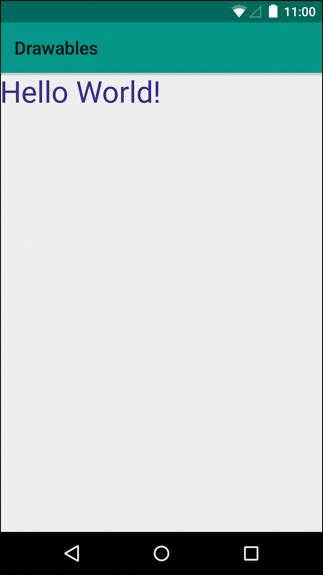
Let’s create a SimpleTextDrawable that just takes a string in the constructor and draws it. One important thing we want to do is to ensure that our Paint is anti-aliased to avoid jaggy, hard edges. The simplest way to do so is to pass in the Paint.ANTI_ALIAS_FLAG constant to the Paint constructor (though there is a setAntiAlias method). In SimpleTextDrawable’s constructor, we want to store the string that’s passed in, set the color of the text, and set a size for it. The color of the text is controlled by the paint, so we simply have to call setColor and pass in an int that represents the color. For this example, we can use a hardcoded value (but feel free to get a color from a Resources instance, if desired). Setting the size is very similar. There is a setTextSize method on Paint, and we can simply use a hardcoded value to make the text large (but, again, feel free to get a dimension from Resources instead).
For our drawable to have a meaningful size, we implement the getIntrinsicHeight and getIntrinsicWidth methods. Our intrinsic dimensions should be large enough to contain the text. For this drawable, let’s keep things simple and have the text on one line. This means that the height is just going to be the text height, which we can get with the getTextSize method of Paint. The width is a little trickier. We need to measure the number of pixels that the text will take up when drawn. Fortunately, Paint has a simple measureText method that we can simply pass our string into.
The setColorFilter and setAlpha methods just pass through to our Paint, so they’re easy enough. We also need to implement getOpacity. Because we’re creating anti-aliased text, some of these pixels will be translucent (meaning they will be partly transparent), so we return PixelFormat.Translucent.
Now for the real work: We need to actually write the text. In the onDraw method, we’ll use one of the Canvas class methods called drawText. We pass in the string to draw, the x offset (we’ll use 0), the y offset, and the Paint instance. One problem is that the text is drawn as if the y position represents a horizontal line to draw on, so the text will be above that position. In other words, we want to pass in the text size for the y position to push down the starting point enough for our text to fit. That’s it! The actual drawing of this text takes a single method call and all the hard parts are done for you behind the scenes. Listing 11.1 shows the full SimpleTextDrawable class.
Listing 11.1 The Full SimpleTextDrawable Class
public class SimpleTextDrawable extends Drawable {
private static final int TEXT_COLOR = 0xFF311B92;
private final Paint mPaint = new Paint(Paint.ANTI_ALIAS_FLAG);
private final String mText;
public SimpleTextDrawable(String text) {
mText = text;
mPaint.setColor(TEXT_COLOR);
mPaint.setTextSize(100);
}
@Override
public int getIntrinsicHeight() {
return (int) mPaint.getTextSize();
}
@Override
public int getIntrinsicWidth() {
return (int) mPaint.measureText(mText);
}
@Override
public void draw(Canvas canvas) {
canvas.drawText(mText, 0, mPaint.getTextSize(), mPaint);
}
@Override
public void setAlpha(int alpha) {
mPaint.setAlpha(alpha);
invalidateSelf();
}
@Override
public void setColorFilter(ColorFilter cf) {
mPaint.setColorFilter(cf);
invalidateSelf();
}
@Override
public int getOpacity() {
return PixelFormat.TRANSLUCENT;
}
}
To test this drawable, you can simply set it as the background of a view. Figure 11.1 shows an example of how this might look without padding.
A Better Text Drawable
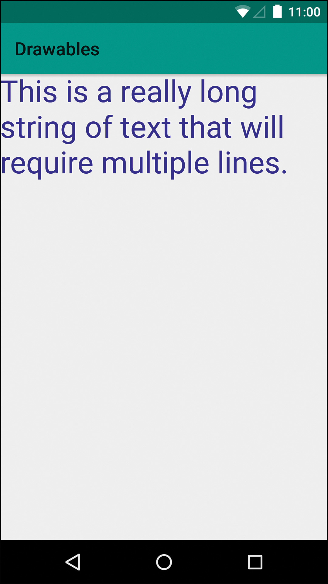
One of the problems we have in that previous drawable is that it doesn’t handle multiple lines. Once the text gets to the edge of the screen, it just keeps going instead of wrapping. You might think that you need to measure word-by-word to figure out where to wrap your text, but Android has help in store in the form of the Layout class. The name of this class isn’t great because it is easily confused with views and layouts of that nature, but it is not the same. For text that doesn’t change (like our example), there is the StaticLayout class. If our text could change, we’d use the DynamicLayout class. These classes do all the size calculations for you, making complex text display pretty easy.
We can create a class called BetterTextDrawable by starting with a copy of our previous drawable. In the constructor, we need to create a StaticLayout using our text, Paint instance, and the width of the text. We also have to specify an alignment (we’ll use ALIGN_NORMAL), a spacing multiplier (remember a value of 1 is single-spaced and 2 is double-spaced), additional spacing, and whether to using the padding specified in the FontMetrics of the font.
This initial StaticLayout is used to give us intrinsic dimensions, so we can override the getIntrinsicHeight and getIntrinsicWidth methods and return the StaticLayout’s getHeight and getWidth results, respectively.
Because we may be displayed at a size other than what we calculated, we need to implement the onBoundsChange method, which is given a Rect that tells us the size to constrain our drawable to. At that point, we can simply create a new StaticLayout. Our draw method can simply call through to the draw method of our StaticLayout and it handles all the text spacing, new lines, and so on. Listing 11.2 shows the full class and Figure 11.2 shows what it can look like.
Listing 11.2 The Full BetterTextDrawable Class
public class BetterTextDrawable extends Drawable {
private static final int TEXT_COLOR = 0xFF311B92;
private final TextPaint mPaint = new TextPaint(new Paint(Paint.ANTI_ALIAS_FLAG));
private final String mText;
private StaticLayout mStaticLayout;
public BetterTextDrawable(String text) {
mText = text;
mPaint.setColor(TEXT_COLOR);
mPaint.setTextSize(100);
mStaticLayout = new StaticLayout(mText, mPaint, (int) mPaint.measureText(mText), Layout.Alignment.ALIGN_NORMAL, 1, 0, false);
}
@Override
public int getIntrinsicHeight() {
return mStaticLayout.getHeight();
}
@Override
public int getIntrinsicWidth() {
return mStaticLayout.getWidth();
}
@Override
public void draw(Canvas canvas) {
mStaticLayout.draw(canvas);
}
@Override
public void setAlpha(int alpha) {
mPaint.setAlpha(alpha);
invalidateSelf();
}
@Override
public void setColorFilter(ColorFilter cf) {
mPaint.setColorFilter(cf);
invalidateSelf();
}
@Override
public int getOpacity() {
return PixelFormat.TRANSLUCENT;
}
@Override
protected void onBoundsChange(Rect bounds) {
mStaticLayout = new StaticLayout(mText, mPaint, bounds.width(), Layout.Alignment.ALIGN_NORMAL, 1, 0, false);
}
}
Depending on your use cases, you might also do some additional work to make this more efficient. For instance, if you’re animating a view by shrinking or growing its height, you might have the onBoundsChange method compare the new width to the old width, to avoid creating a new StaticLayout when it hasn’t changed.
Working with Images
Android has several methods to make working with images easier as well, so you don’t have to worry about char arrays or other low-level representations of images. This means that common operations like copying one image into another (perhaps larger) image takes a line of code and you don’t even have to worry about loops.
The typical path when working with images in a drawable is to get a Bitmap instance either via BitmapFactory or one of the static Bitmap methods and then draw it using one of the Canvas drawBitmap methods. Let’s make a class called SimpleBitmapDrawable to take a closer look at this process.
First, the constructor should take a Bitmap, because we always want to have something to draw, but we can make a setBitmap method that handles receiving a new Bitmap. In the setBitmap method, we need to store a reference to the bitmap and call invalidateSelf (because we have something to draw).
Like with any drawable we make, we should override the getIntrinsicHeight and getIntrinsicWidth methods. Similar to the previous drawable, we can return the getHeight and getWidth results, respectively, from our Bitmap instance (instead of the StaticLayout instance).
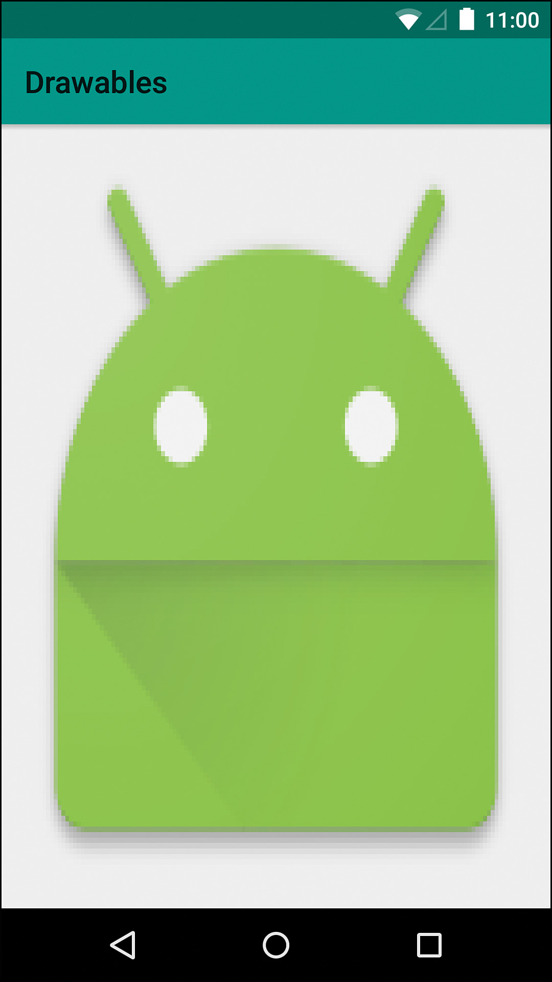
Now we just need to override draw. There are several drawBitmap methods that Canvas offers us. In this case, let’s use the method that takes the Bitmap instance, a source Rect, a destination Rect, and a Paint. The source Rect tells which portion of the bitmap to draw and the destination Rect tells where to draw it. Android will handle the scaling automatically. If we exclude the source Rect and use the bounds of the drawable as the destination Rect, we effectively stretch the image to fill the space allotted to the drawable. Figure 11.3 shows what this looks like when provided the small app icon. Listing 11.3 show the full source.
Listing 11.3 The Full SimpleImageDrawable Source
public class SimpleImageDrawable extends Drawable {
private Bitmap mBitmap;
private final Paint mPaint = new Paint(Paint.ANTI_ALIAS_FLAG);
public SimpleImageDrawable(Bitmap bitmap) {
setBitmap(bitmap);
}
@Override
public void draw(Canvas canvas) {
canvas.drawBitmap(mBitmap, null, getBounds(), mPaint);
}
@Override
public int getIntrinsicHeight() {
return mBitmap.getHeight();
}
@Override
public int getIntrinsicWidth() {
return mBitmap.getWidth();
}
@Override
public int getOpacity() {
return PixelFormat.TRANSLUCENT;
}
@Override
public void setAlpha(int alpha) {
int oldAlpha = mPaint.getAlpha();
if (alpha != oldAlpha) {
mPaint.setAlpha(alpha);
invalidateSelf();
}
}
/**
* Sets the {@link Bitmap} to draw and invalidates itself
*
* @param bitmap Bitmap to draw with rounded corners
*/
public void setBitmap(@NonNull Bitmap bitmap) {
mBitmap = bitmap;
invalidateSelf();
}
@Override
public void setColorFilter(ColorFilter cf) {
mPaint.setColorFilter(cf);
invalidateSelf();
}
}
Color Filters
Android also has support for color filters. These filters provide ways of manipulating the pixels that are drawn in complex ways. You use these color filters by calling a Paint instance’s setColorFilter method.
Lighting Color Filter
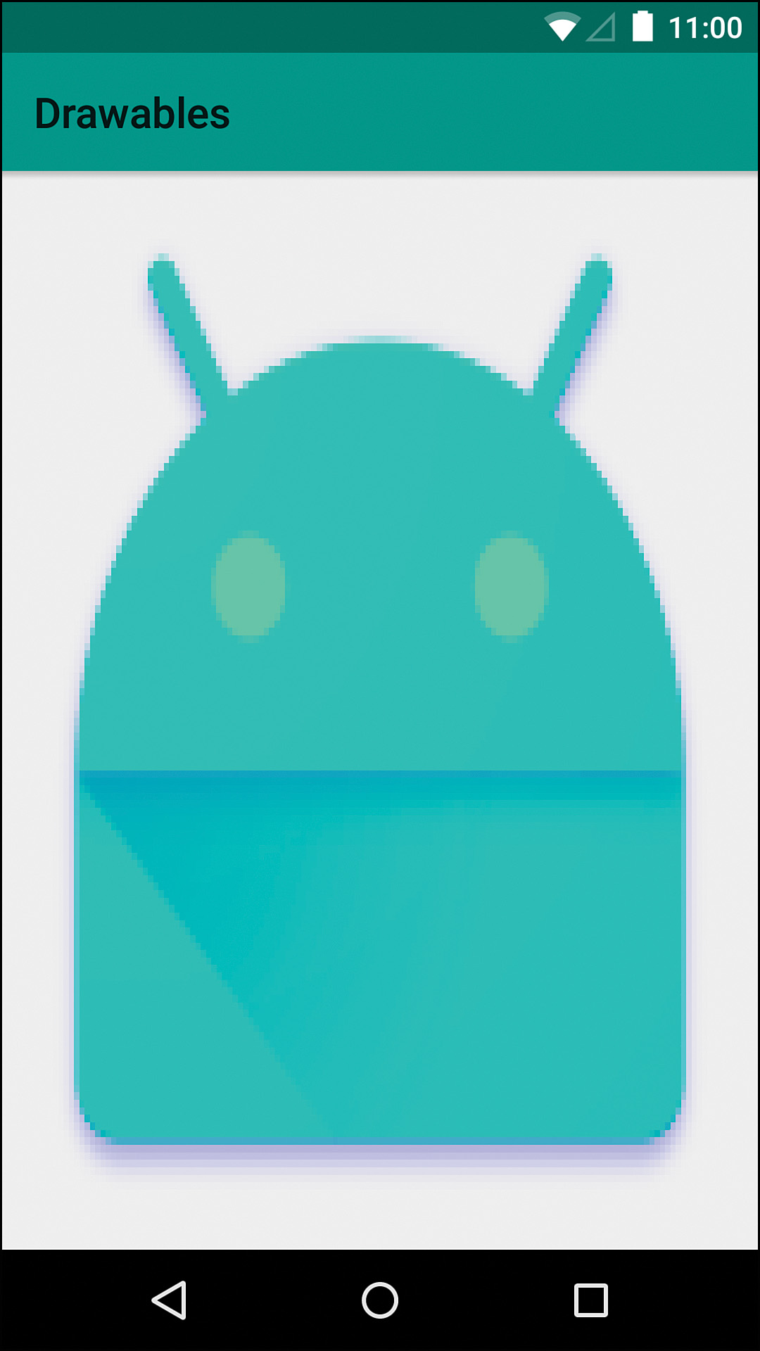
The LightingColorFilter class is a color filter that allows you to multiply and add to the RGB color channels. To use it, you simply construct a LightingColorFilter, passing in an int to multiply the color channels by and an int to add to each color channel, and then call setColorFilter on your Paint instance passing in the color filter. Each int you are passing in should be a full color. For instance, you can pass 0xFF00FF00 for the multiplier. The 0x says that this is an int specified in hexadecimal. The first FF says don’t change the alpha channel (effectively the same as multiplying a number by 1). The next 00 is to remove the red (multiplying the red by 0). The next FF keeps the green at its current level and the last 00 removes all blue. This alone would allow you to basically eliminate the red and blue pixels in an image, but you can also pass in a second int to the constructor that is added to the channels. For instance, if you pass in 0x000000BB as the added int, you are saying not to add to any channel except blue. Given that we kept the green channel intact, this would make our icon a bit of a cyan color (green and blue mix). Figure 11.4 shows the effect of the color filter using these values.
Color Matrix
The ColorMatrixColorFilter is a lot like the LightingColorFilter but with more control. The color matrix is an array of ints to describe how to manipulate the channels. There are four sets of five values (one set for each channel in RGBA order). The first value in a set is the multiplier for the red channel. The second is the multiplier for green. The third is a multiplier for blue. The fourth is the multiplier for alpha, and the final one is the additional amount to add to the channel. This means that you can do interesting things like adjust the green channel of the image based on the values in the red channel. This lets you do some very powerful color manipulation.
At this point, many people are scared away from using the ColorMatrixColorFilter. Figuring out the exact values you need can be difficult and a lot of times you want some relatively simple effect. For instance, what if you wanted to make an image orange? If you control the images, then Photoshop makes this easy enough, but what about times when you’re getting your images from a source outside of your control such as the web or from the OS itself? Older versions of Android didn’t have the setTint method, but you can still use a ColorMatrixColorFilter to color images in a wide variety of ways programmatically.
First, create a new ColorMatrix and call setSaturation, passing in 0. This gives you a matrix which will convert an image to gray scale. Now you can create another ColorMatrix and use the setScale method to set the amount of color scaling (multiplying) for each channel. If we pass in 2f, 0.68f, 0.26f, and 1f, we’ll end up with a bright orange (remember this is just how much to affect the red, green, blue, and alpha channels respectively). Next we need to combine the two matrices, so we call postConcat with our first matrix and pass in the second one. Now that we have a ColorMatrix that contains our manipulations, we can create a new ColorMatrixColorFilter and pass in our ColorMatrix and then call setColorFilter to apply it. Figure 11.5 shows our drawable with the ColorMatrixColorFilter applied and Listing 11.4 shows the lines of code to make it happen.
Listing 11.4 The SimpleImageDrawable Modified by a ColorMatrixColorFilter
final SimpleImageDrawable simpleImageDrawable = new SimpleImageDrawable(bitmap);
final ColorMatrix colorMatrix = new ColorMatrix();
colorMatrix.setSaturation(0);
final ColorMatrix colorScale = new ColorMatrix();
colorScale.setScale(2f, .68f, .26f, 1f); // Orange
colorMatrix.postConcat(colorScale);
simpleImageDrawable.setColorFilter(new ColorMatrixColorFilter(colorMatrix));
PorterDuff Image Compositing
Android supports PorterDuff image compositing. Thomas Porter and Tom Duff wrote a seven-page paper titled “Compositing Digital Images” back in 1984 that explained methods of combining two or more images that have become extremely common in applications for mobile and desktop.
Android identifies the specific compositing method by using an enum, which is really just telling the native code which method to call. Unfortunately, the Android documentation for PorterDuff.Mode enums is very limited. It gives you the name and a formula, and you’re expected to understand the rest. At first, the formulas look a bit foreign, but most are not too bad once you understand what the letters mean and what the goal is.
For all the formulas, an S represents the source image and a D represents the destination image. An a represents the alpha channel and a c represents the color channels (a color being made of a red channel, a green channel, a blue channel, and an optional alpha channel). For all these composition modes, the color channels are treated individually and do not interact with other channels. If you are adding the source color to the destination color, you are adding the red channel of the source to the red channel of the destination, the green channel of the source to the green channel of the destination, and the blue channel of the source to the blue channel of the destination. Obviously, that’s a bit wordy, so it can be expressed as “Sc + Dc” (source color plus destination color) instead.
Multiplication is not too much different, except you can better understand it by thinking of individual channels as floats. If 0 represents the minimum value of the channel and 1 represents the maximum value of the channel, you have infinite values (in reality it is limited by the precision of the data type, but that’s an implementation detail). In fact, this is how OpenGL works. These values can be converted to a specific bit depth when needed (e.g., if you represent color with 256 values per channel, a value of .25f would be about 64). These channels can also be multiplied. For instance, you can take a green value of .2f and a green value of .5f and multiply them together you have a value of .1f, which equates to a color value of about 26.
Some of the modes to follow refer to the inverse of a channel. The inverse is what you get when you take the maximum value (1f) and subtract the current value. For instance, the inverse of .25f would be .75f because 1f – .25f is .75f. This is not the opposite color (also called complementary color) because it is for a single channel. For example, if you had a fully green color (0f red, 1f green, 0f blue), the inverse would be magenta (1f red, 0f green, 1f blue).
Modes
Each of the PorterDuff methods is referred to as a Mode in Android. When using a Paint object, you can give it an Xfermode (“transfer mode”) that is used when drawing. To give it a PorterDuff.Mode, you have to use the PorterDuffXfermode object, passing in the Mode enum that you want to use.
In some explanations of PorterDuff compositing, you might see the two images referred to as “A” and “B,” but Android calls them the source (“SRC”) image and the destination (“DST”) image. In Android, the destination image is the one you are drawing the source into. Several of the methods have both a source image version and a destination image version, which can be helpful if the Bitmap backing your Canvas for one of your images is mutable but the other one is not. For example, SRC_OVER draws the source image over the top of the destination image. DST_OVER draws the destination image over the source image. To simplify the explanations, this book describes only the source versions in detail, but both types are included in the sample images.
As you look through these, you may realize many (if not all) are similar to the effects you have seen or used in graphics editing programs. Sometimes these are called “blend modes” or use other terminology but the concepts are exactly the same.
Clear
Formula: [0, 0]
“Clear” simply means that nothing will be drawn in the completed image. This is typically used to “erase” some portion of an image. See the example in Figure 11.6.

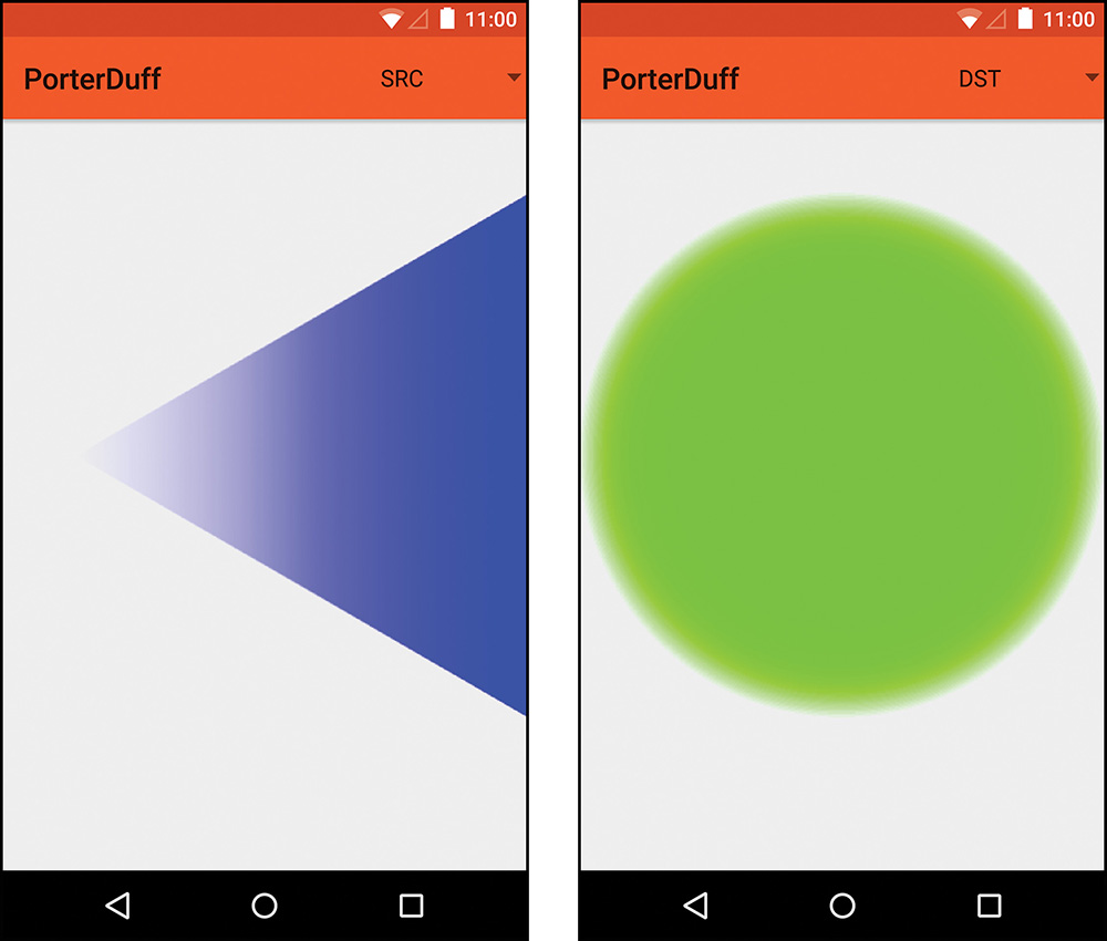
SRC and DST
Formula: [Sa, Sc]
These two modes are fairly simple. If you use SRC, then only the source image is drawn. Similarly, if you use DST, only the destination image is drawn. You will probably rarely (if ever) use these because you can usually eliminate the need to create one of the two images earlier, if you are able to determine it is not needed. See the example of SRC and DST in Figure 11.7.
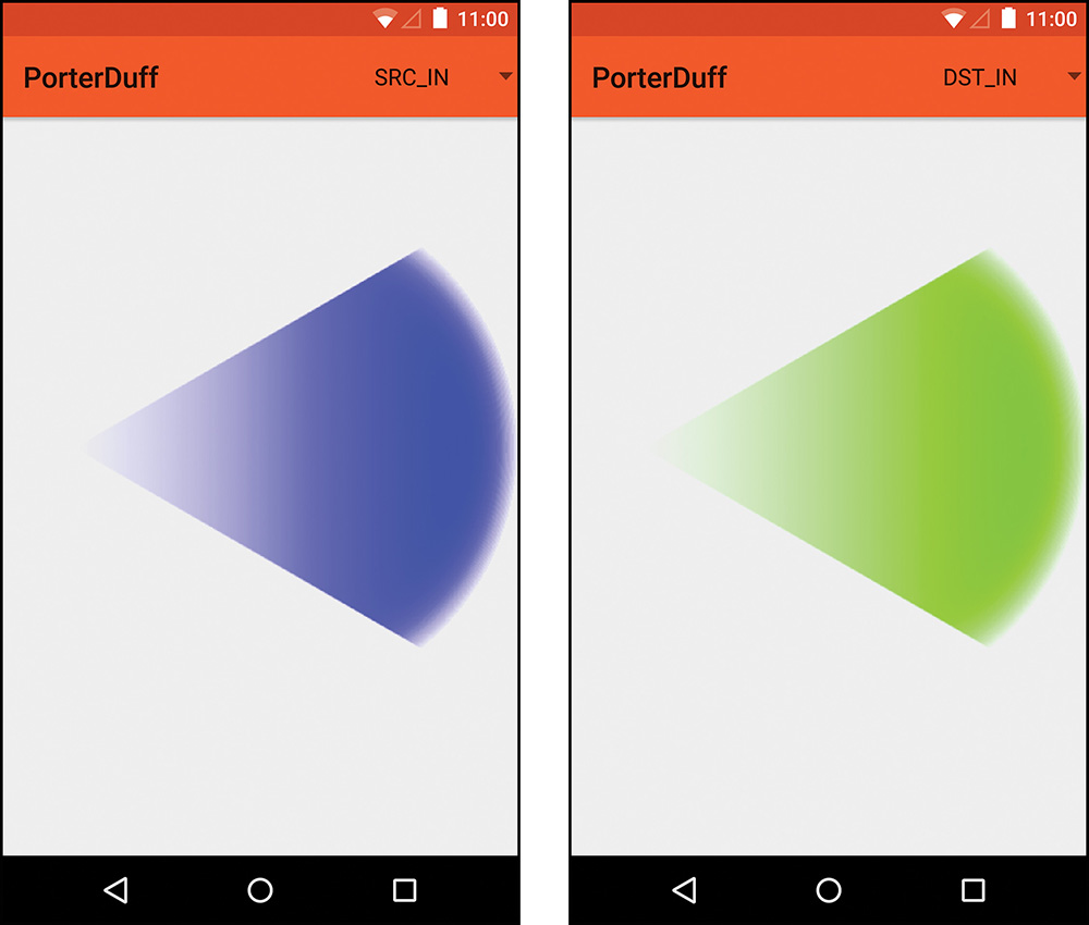
“Source in” multiplies the source’s alpha and color by the destination’s alpha. This means that you’re replacing the destination with the source where they overlap. Because both the color and alpha are multiplied, anywhere they don’t overlap is cleared. In other words, the source is in place of the destination. See Figure 11.8 for an example.
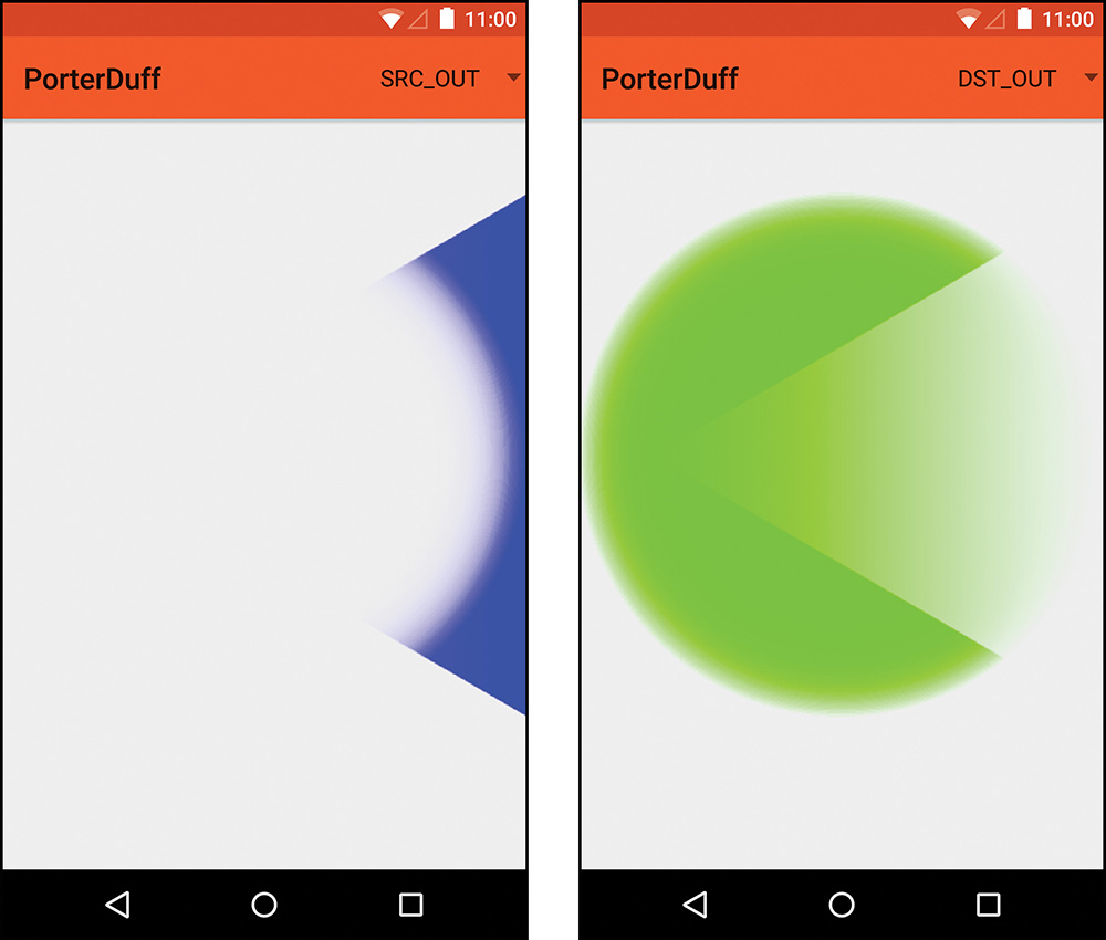
SRC_OUT and DST_OUT
Formula: [Sa × (1 – Da), Sc × (1 – Da)]
The “out” methods are basically the opposite of the “in” methods. When you’re using SRC_OUT, only the part of the source image that does not overlap the destination image will be drawn. “Source out” multiplies the source’s alpha and color by the inverse of the destination’s alpha. Anywhere that the destination is fully transparent, the source will be fully opaque. If the destination is fully opaque somewhere, the source will not be visible. You are placing the source outside of the destination’s alpha channel. See Figure 11.9 for an example.
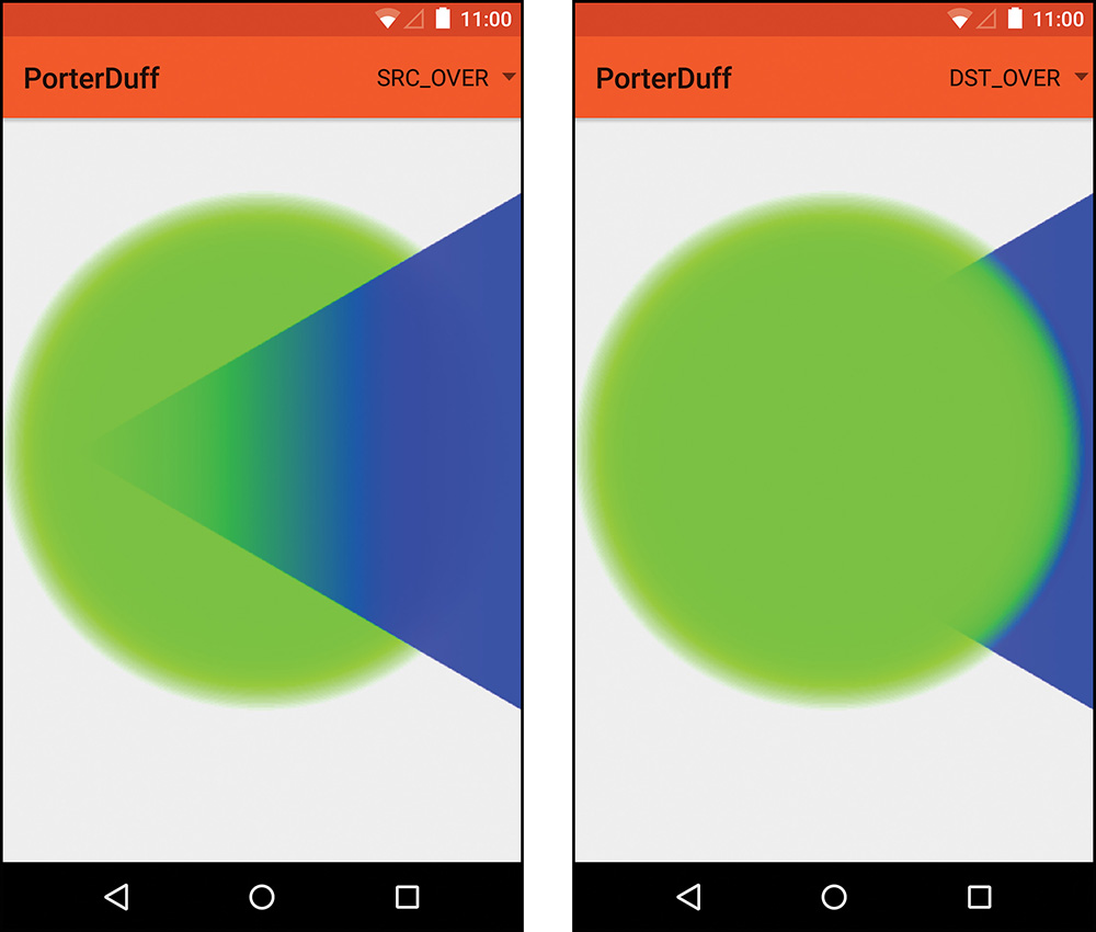
SRC_OVER and DST_OVER
Formula: [Sa + (1 – Sa) × Da, Sc + (1 – Sa) × Dc]
“Source over” is a bit trickier to understand in terms of the math, but the end result is easy to understand. The source is placed over the top of the destination. The inverse of the source’s alpha channel is multiplied by the destination’s alpha channel and then the source’s alpha is added back to it. The color is also modified in a similar manner. The inverse of the source’s alpha is multiplied by the destination’s color and then the sources color is added. See Figure 11.10 for an example.
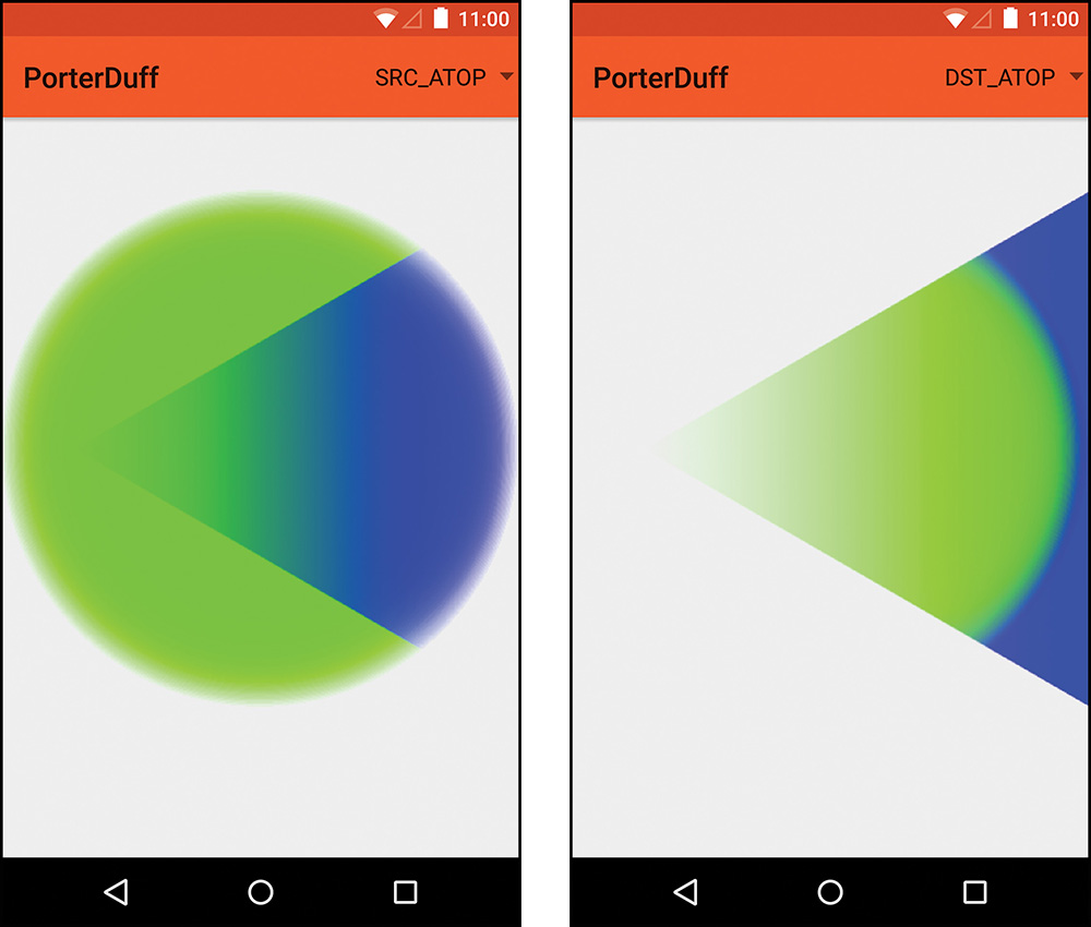
“Source atop” puts the source image on top of the destination image, but only where they overlap. It directly uses the destination’s alpha channel for the resulting alpha values. The color is determined by taking the source color times the destination alpha and then adding back the result of the inverse of the source alpha multiplied by the destination color. Basically, it’s putting the source on top of the destination using the destination’s alpha value; then, for however transparent the source is, that amount of the destination shows through. See Figure 11.11 for an example.
Lighten
Formula: [Sa + Da – Sa × Da, Sc × (1 – Da) + Dc × (1 – Sa) + max(Sc, Dc)]
The “lighten” mode combines the two images and will only brighten the areas where they overlap. The areas that are fully opaque in one image and fully transparent in the other will take the opaque portions without modification. For the alpha channel, the source and destination alphas are added together and the product of the two is subtracted from that result. To determine the color, you multiply the source color times the inverse of the destination alpha, add the destination color times the inverse of the source, and add whichever is greater, the source or the destination color. See Figure 11.12 for an example.

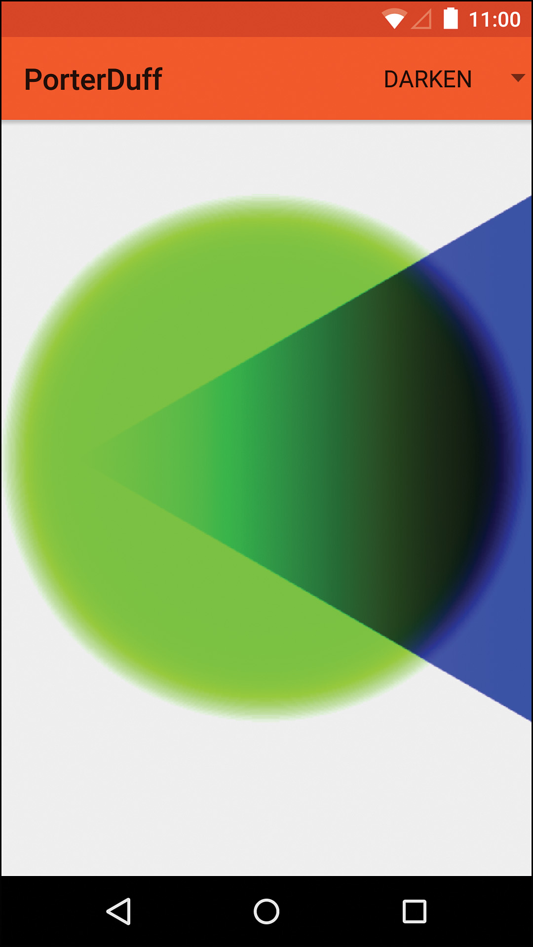
Darken
Formula: [Sa + Da – Sa × Da, Sc × (1 – Da) + Dc × (1 – Sa) + min(Sc, Dc)]
The “darken” mode is extremely similar to the lighten mode. Anywhere that is opaque on one image and transparent in the other uses the opaque version without modification; however, anywhere that has some opacity in either image results in the color being darker because the final addition in the color calculation takes the darker of the two color values instead of the brighter. See Figure 11.13 for an example.
The “add” mode literally adds the source values to the destination values and then clamps them to the maximum value if they’re too large. See Figure 11.14 for an example. The formula calls this clamping “saturate” because of the name of the Skia method, but it’s just limiting the maximum value.
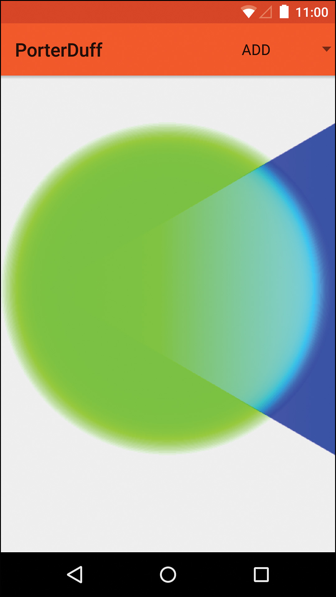
For instance, if the source has .7f for the red channel and the destination has .6f for the red channel, you get 1.3f. Because that’s greater than the maximum value of 1f, the result is 1f. Addition always brightens colors (unless you’re adding a black image, in which case it does not affect the other image). Note that this Mode was added in API level 11 despite the fact that the documentation does not say so.
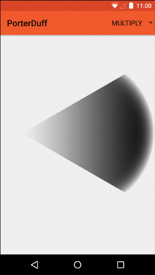
Multiply
Formula: [Sa × Da, Sc × Dc]
The “multiply” mode is one of the easiest to understand from a math perspective, but it can take a few examples before you understand the visuals. The source alpha and destination alpha are multiplied to get the resulting alpha channel, so only pixels that are fully opaque in the source and destination images will be fully opaque in the resulting image. The source color and the destination color are multiplied to get the resulting color. The name “multiply” is obviously very fitting when you look at the math. Because you’re multiplying values that are never bigger than 1, you will never get a brighter color when multiplying. Multiplying pure white would just give you whatever the other color was because each channel is represented by a 1f. This means that, except in the case of white, multiplying will always give you darker colors. Anywhere that is fully transparent on either image results in transparency. See Figure 11.15 for an example.

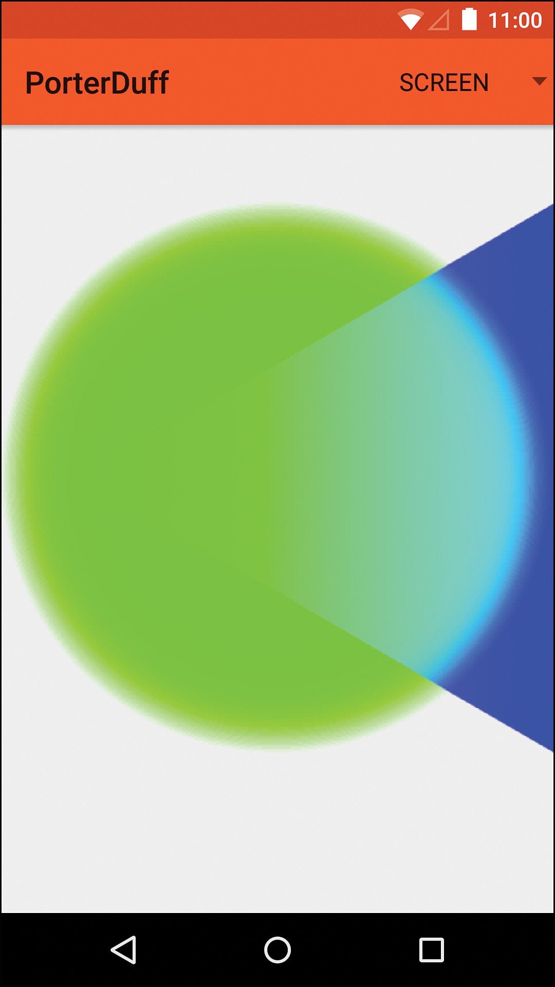
Screen
Formula: [Sa + Da – Sa × Da, Sc + Dc – Sc × Dc]
The “screen” mode results in images that are very similar to the “lighten” and “add” modes. In fact, the alpha channel is calculated the exact same way for lighten and screen; the difference is that the color for the screen mode is calculated the same way as the alpha (whereas the lighten mode handles it differently). See Figure 11.16 for an example. Note that this Mode was added in API level 11 despite the fact that the documentation does not say so.
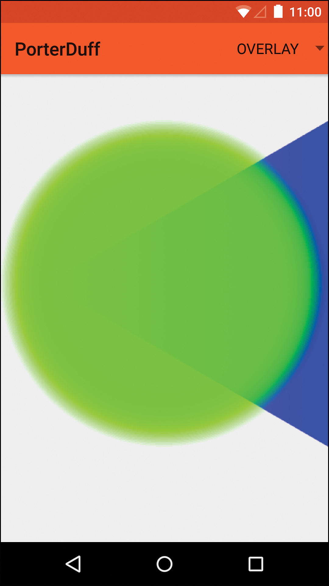
Overlay
This is the one Mode where the formula is not included, and that’s because it is variable. If double the destination color is less than or equal to the destination alpha, one formula is used; otherwise, another formula is used. The alpha is calculated the same way as screen, though. The key difference is the way that the colors are blended. See Figure 11.17 for an example. Note that this Mode was added in API level 11 despite the fact that the documentation does not say so.
XOR
Formula: [Sa + Da – 2 × Sa × Da, Sc × (1 – Da) + (1 – Sa) × Dc]
“Exclusive or” is another that’s easier to visually understand. Anywhere that the source and destination overlap is cleared. This is done by adding the source and destination alpha channels and subtracting double the product of the source and destination alpha channels. The color is determined by multiplying the source color by the inverse of the destination’s alpha, multiplying the destination color by the inverse of the source’s alpha, and combining the result. See Figure 11.18 for an example.

Shaders
In a generalized sense, a shader provides the Paint object with pixels (colors) to draw. A simple example is a gradient such as a LinearGradient. When you use a Paint to draw a rectangle on the Canvas, for instance, the Paint gets the color for each pixel from the left to the right via the Shader instance. There are three types of shaders. The first is BitmapShader, which provides pixels from a bitmap. The second is a gradient shader, which allows you to draw a gradient that uses two or more colors. The concrete implementations are LinearGradient, RadialGradient, and SweepGradient. The last type of shader is called ComposeShader and it simply combines two shaders into one.
Round Images
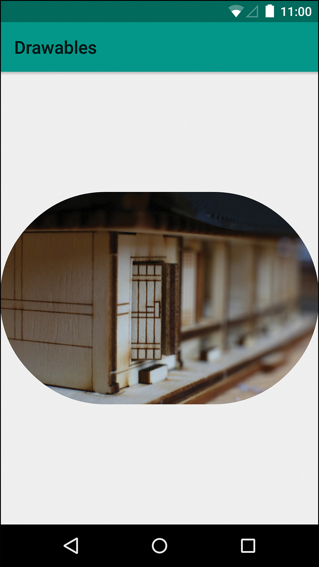
To understand shaders better, it’s a good idea to create a simple example. What if you wanted to create a round version of an image such as a profile picture? You would do this by drawing a circle with a BitmapShader. Although there is now a RoundedBitmapDrawable in the support library, understanding how you would implement something like this will make it more clear what’s actually going on and how you might use a similar technique for a specific use case that you have down the road.
Making a copy of SimpleBitmapDrawable gives us a good starting point. We need to update the constructor to take an int that will be the radius to round the image with. The draw method will call drawRoundRect on the Canvas instance, passing in a RectF, our radius, and our Paint instance. We also need to update setBitmap so that after getting a reference to the new Bitmap instance, we create a new BitmapShader using that instance. When creating this type of shader, we have to specify the tiling mode, which is how the shader figures out which colors to use when you paint beyond the end of the bitmap. We’re not going to be doing that, so the value we set doesn’t really matter, but we can use CLAMP, which just means it repeats the very last column/row of pixels. Now we call the Paint instance’s setShader method and pass in this BitmapShader. The last thing we need to do is override onBoundsChange and update our destination RectF that we use when drawing. Figure 11.19 shows an example of an image that has had the corners rounded using the drawable code in Listing 11.5.
Listing 11.5 The Full RoundedBitmapDrawable Source
public class RoundedImageDrawable extends Drawable {
private Bitmap mBitmap;
private int mRadius;
private final Paint mPaint = new Paint(Paint.ANTI_ALIAS_FLAG);
private final RectF mDestinationRectF = new RectF();
public RoundedImageDrawable(Bitmap bitmap, int radius) {
mRadius = radius;
setBitmap(bitmap);
}
@Override
public void draw(Canvas canvas) {
canvas.drawRoundRect(mDestinationRectF, mRadius, mRadius, mPaint);
}
@Override
public int getIntrinsicHeight() {
return mBitmap.getHeight();
}
@Override
public int getIntrinsicWidth() {
return mBitmap.getWidth();
}
@Override
public int getOpacity() {
return PixelFormat.TRANSLUCENT;
}
@Override
public void setAlpha(int alpha) {
int oldAlpha = mPaint.getAlpha();
if (alpha != oldAlpha) {
mPaint.setAlpha(alpha);
invalidateSelf();
}
}
/**
* Sets the {@link Bitmap} to draw and invalidates itself
*
* @param bitmap Bitmap to draw with rounded corners
*/
public void setBitmap(@NonNull Bitmap bitmap) {
mBitmap = bitmap;
final Shader shader = new BitmapShader(bitmap, Shader.TileMode.CLAMP, Shader.TileMode.CLAMP);
mPaint.setShader(shader);
invalidateSelf();
}
@Override
public void setColorFilter(ColorFilter cf) {
mPaint.setColorFilter(cf);
invalidateSelf();
}
@Override
protected void onBoundsChange(Rect bounds) {
mDestinationRectF.set(bounds);
}
}
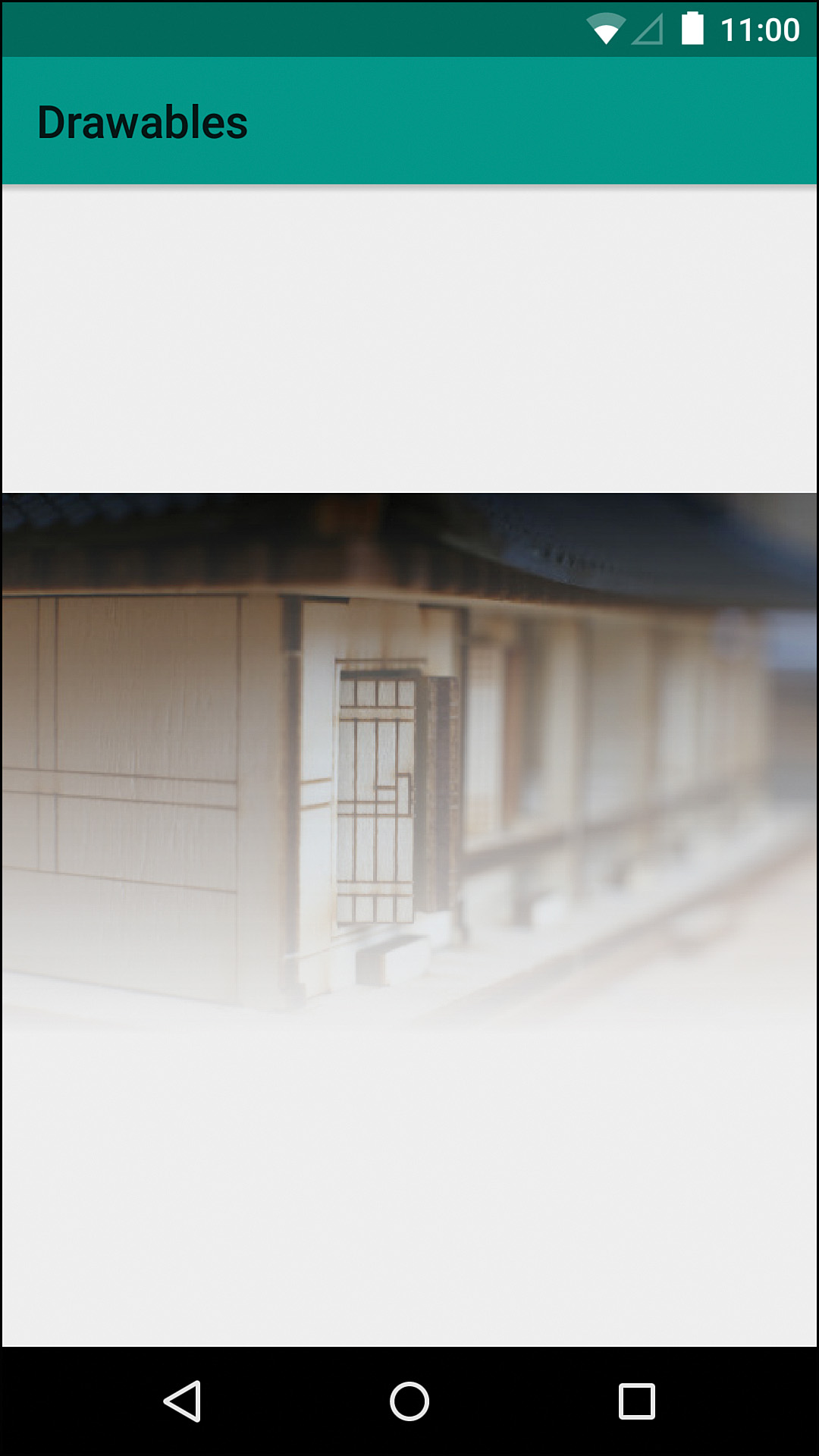
Gradient Fades
If you wanted to fade a portion of an image, you can simply combine two of the techniques from this chapter. First, you draw the gradient that you want, and then you draw the image over that gradient, using the SRC_IN mode.
We can start by copying SimpleImageDrawable and calling it FadedImageDrawable. We can create a private final Xfermode by creating a new PortDuffXfermode and passing in SRC_IN. Now we simply have to update the setBitmap method. We’re going to create a new Bitmap with the static createBitmap method and then create a Canvas to draw into it with. Then we create a LinearGradient, which has a fairly lengthy constructor. The first pair of arguments specifies where the starting point is and the next two specify the ending point (as if you were drawing the line that the gradient follows). We’re just going to fade from the top to the bottom, but you could make these whatever makes sense to you. Next, we pass the starting color and ending color. We only care about the alpha values, so we specify fully opaque and fully transparent, respectively. Finally, it requires a tiling mode, which we can use CLAMP for. With the shader ready, we can call setShader and pass in the LinearGradient.
With the local Canvas instance, we can simply draw a rectangle with drawRect. The shader makes that rectangle a gradient from fully opaque to fully transparent. After drawing the gradient, we pass null into setShader to avoid using it for the next part. We also call setXfermode, passing in the Xfermode we created earlier, and draw the bitmap. Because the Xfermode is using SRC_IN, the bitmap uses the alpha of the pixels already in the bitmap to determine the alpha of the pixels being drawn.
Lastly, we pass null into setXfermode to avoid using it when we actually draw the bitmap in the draw method. Triggering invalidateSelf ensures that draw will be called soon and this faded bitmap that we’ve created will be displayed. Figure 11.20 shows an example of an image using this drawable and the code is in Listing 11.6.
Listing 11.6 The Full FadedImageDrawable Source
public class FadedImageDrawable extends Drawable {
private Bitmap mBitmap;
private final Paint mPaint = new Paint(Paint.ANTI_ALIAS_FLAG);
private final Xfermode mXfermode = new PorterDuffXfermode(PorterDuff.Mode.SRC_IN);
public FadedImageDrawable(Bitmap bitmap) {
setBitmap(bitmap);
}
@Override
public void draw(Canvas canvas) {
canvas.drawBitmap(mBitmap, null, getBounds(), mPaint);
}
@Override
public int getIntrinsicHeight() {
return mBitmap.getHeight();
}
@Override
public int getIntrinsicWidth() {
return mBitmap.getWidth();
}
@Override
public int getOpacity() {
return PixelFormat.TRANSLUCENT;
}
@Override
public void setAlpha(int alpha) {
int oldAlpha = mPaint.getAlpha();
if (alpha != oldAlpha) {
mPaint.setAlpha(alpha);
invalidateSelf();
}
}
/**
* Sets the {@link Bitmap} to draw and invalidates itself
*
* @param bitmap Bitmap to draw with rounded corners
*/
public void setBitmap(@NonNull Bitmap bitmap) {
mBitmap = Bitmap.createBitmap(bitmap.getWidth(), bitmap.getHeight(), Bitmap.Config.ARGB_8888);
final Canvas canvas = new Canvas(mBitmap);
final LinearGradient linearGradient = new LinearGradient(0, 0, 0, bitmap.getHeight(), 0xFF000000, 0x00000000, Shader.TileMode.CLAMP);
mPaint.setShader(linearGradient);
canvas.drawRect(0, 0, mBitmap.getWidth(), mBitmap.getHeight(), mPaint);
mPaint.setShader(null);
mPaint.setXfermode(mXfermode);
canvas.drawBitmap(bitmap, 0, 0, mPaint);
mPaint.setXfermode(null);
invalidateSelf();
}
@Override
public void setColorFilter(ColorFilter cf) {
mPaint.setColorFilter(cf);
invalidateSelf();
}
}
Summary
In this chapter, you learned about advanced image compositing techniques by using PorterDuff.Modes. You should now understand how to create Bitmaps to draw into using advanced painting techniques. You should know the basic concepts behind a Shader as well as how to instantiate and apply them to Paint objects. You can bring all this knowledge together in custom Drawables to make it easy to apply advanced drawing techniques to a variety of views.
In the next chapter, you’ll begin to more deeply understand Android’s views, including how to apply the techniques from this chapter directly to a custom view without the need for a separate drawable.