
Chapter 3 Advanced Commands
3-1 Introduction
This chapter explains how to use some of the more advanced AutoCAD commands. Included are the Osnap, Grips, Layer, Block, and Attribute commands.
3-2 Osnap
The Object Snap command allows you to snap to entities on the drawing screen rather than just to points, as does the Snap command. Osnap can snap to the endpoint of a line, to the intersection of two lines, or to the center point of a circle, as well as to other items. The Osnap dialog box allows you to access the various Osnap commands.
To Access the Osnap Commands
 Locate the cursor on the Osnap tool located at the bottom of the screen.
 Click the arrowhead.
A listing of Osnap options will appear. See Figure 3-1.
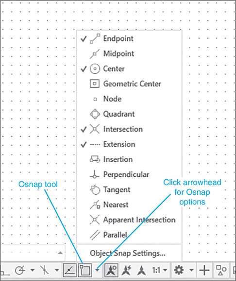
Figure 3-1
Osnap can also be accessed by holding down the <Ctrl> key and pressing the right mouse button. This feature can be activated during any command sequence. A dialog box will appear on the screen listing the Osnap options. See Figure 3-2.
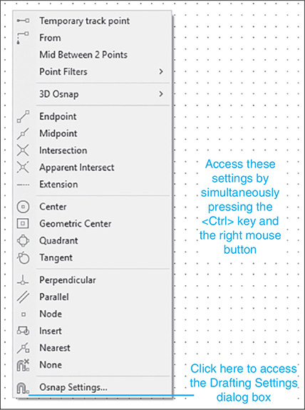
Figure 3-2
The Object Snap Settings tool allows you to access the options located under the Object Snap tab on the Drafting Settings dialog box. See Figure 3-3. The Object Snap dialog box can be used to turn an Osnap option on permanently—that is, the option will remain on until you turn it off. If the Endpoint option is on, the cursor will snap to the nearest endpoint every time a point selection is made. Turning an Osnap option on is very helpful when you know that you are going to select several points of the same type; however, in most cases, it is more practical to activate an Osnap option as needed by using the Osnap tool or the Osnap menu.
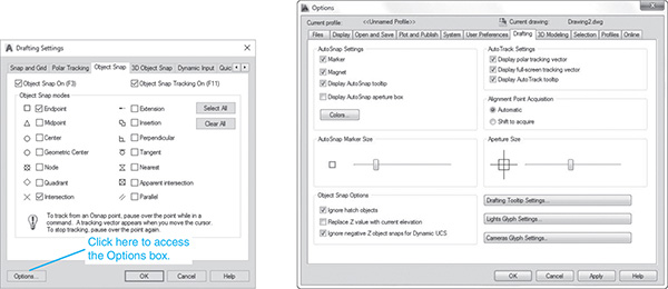
Figure 3-3
To Turn Osnap On
- You can access the Object Snap dialog box in one of two ways: Right-click the Object Snap icon at the bottom of the screen and click the Settings option, or hold down the <Ctrl> key, right-click the mouse, and click the Osnap Settings option.
The Drafting Settings dialog box will appear. See Figure 3-3.
- Click the box to the left of the command that you wish to activate. A check mark will appear, indicating that the command is active.
 Close the Drafting Settings dialog box.
The Options box on the Drafting Settings dialog box allows you to access the Options dialog box, which can be used to change the color of the cursor box used to identify osnap points.
To Change the Size of the Osnap Cursor Box
The Options dialog box also contains an Aperture Size option. This option allows you to change the size of the rectangular box on the cursor. A larger box makes it easier to grab objects, but too large a box may grab more than one object or the wrong object.
3-3 Osnap—Endpoint
The Endpoint option is used to snap to the endpoint of an existing entity. Figure 3-4 shows an existing line.
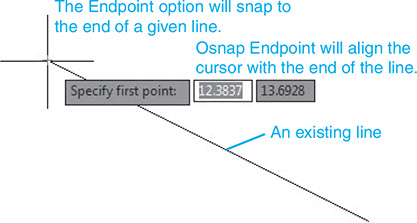
Figure 3-4
To Snap to the Endpoint of an Existing Line
- Select the Line tool from the Draw panel.
Command: _line Specify first point:
- Select the Endpoint tool from the Object Snap dialog box.
Specify next point or [Undo]: _endp of
Most of the Osnap options do not work independently, but in conjunction with other commands. In this example, the Line command must be activated first, then the Osnap command. Note that a box will appear around the endpoint of the line, indicating that the Osnap Endpoint command has selected the line’s endpoint. The Endpoint command also works with arcs, mlines, and 3D applications.
3-4 Osnap—Snap From
The Snap From option allows you to grab the line directly, without having to enter another command. See Section 3-15, Grips.
If you first click the Snap From option and then select a line, the endpoints and midpoint of the line will be defined by boxes. See Figure 3-5. The points selected in Figure 3-5 are selected at random locations.
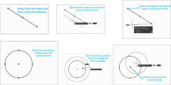
Figure 3-5
To Move a Line
- Select the line’s midpoint box.
The box will change to a filled red box.
- Move the cursor, and the line moves with the cursor.
- Select a new location for the line.
To Change the Angle and Length of a Line
- Select one of the designated endpoint boxes created from the Snap From option.
The box will change to a filled red box.
- Move the cursor, and the line’s endpoint will move with the cursor.
- Select a new angle and length for the line.
To Apply the Snap From Option to a Circle
- Select the Snap From option, then the circle.
The four quadrant points and the circle’s midpoint are defined by boxes. See Figure 3-5.
- Select the circle’s center point to move the circle, or select one of the quadrant points to change the circle’s diameter.
3-5 Osnap—Midpoint
The Midpoint option is used to snap to the midpoint of an existing entity. In the example presented in Figure 3-6, a circle is to be drawn with its center point at the midpoint of the line.

Figure 3-6
To Draw a Circle About the Midpoint of a Line
- Select the Circle tool from the Draw panel.
Command: _circle Specify center point for circle or [3P 2P Ttr
(tan tan radius)]:
- Select the Snap to Midpoint tool from the Object Snap dialog box.
Command:_circle Specify center point for circle or [3P 2P Ttr
(tan tan radius)]:_mid of
- Select the line.
Specify radius of circle or [Diameter]:
 Select a radius value.
3-6 Osnap—Intersection
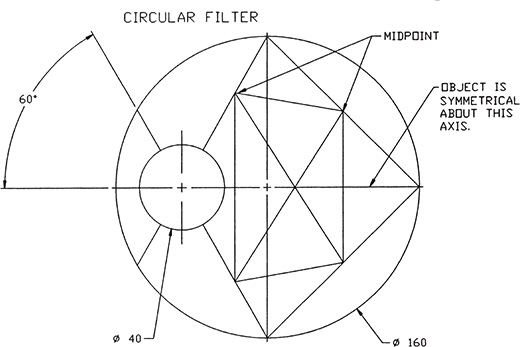
The Intersection option is used to snap to the intersection of two or more entities. Figure 3-7 shows a set of projection lines that are to be used to define an ellipse.
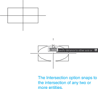
Figure 3-7
To Use the Osnap Intersection Command to Define an Ellipse
- Select the Ellipse tool from the Draw panel.
Specify axis endpoint of ellipse or [Arc Center]:
- Select the Intersection tool from the Object Snap dialog box.
Specify axis endpoint of ellipse or [Arc Center]: _int of
- Select the first point for the ellipse.
Specify other endpoint of axis:_int of
- Select the Intersection option, and then select the second point.
Select the intersection that defines the length of one of the axes from the ellipse center point. In this example, the distance between the two points selected equals the length of the major axis of the ellipse.
Specify distance to other axis or [Rotation]:_int of
 Select the Intersection tool from the Object Snap dialog box, and select the intersection that defines the other axis length.
3-7 Osnap—Apparent Intersection
The Apparent Intersection option is used to snap to an intersection that would be created if the two entities were extended to create an intersection. Figure 3-8 shows two lines that do not intersect, but if continued, would intersect.
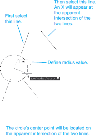
Figure 3-8
To Draw a Circle Centered About an Apparent Intersection
- Select the Circle tool from the Draw panel.
Command: _circle Specify center point for circle or [3P 2P Ttr (tan
tan radius)]:
- Select the Apparent Intersection tool from the Object Snap dialog box.
Command: _circle Specify center point for circle or [3P 2P Ttr (tan
tan radius)]: _appint of
- Select one of the lines.
Command: _circle Specify center point for circle or [3P 2P Ttr (tan
tan radius)]: _appint of
- Select the other line.
Specify radius of circle or [Diameter]:
- Define a radius value for the circle.
3-8 Osnap—Center
The Center option is used to draw a line from a given point directly to the center point of a circle. See Figure 3-9.
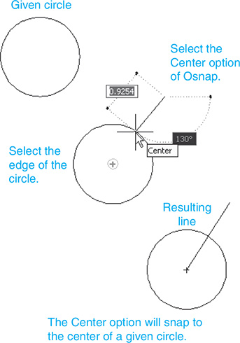
Figure 3-9
To Draw a Line to the Center Point of a Circle
- Select the Line tool from the Draw panel.
Command: _line Specify first point:
- Select the start point for the line.
Specify next point or [Undo]:
- Select the Center tool from the Object Snap dialog box.
Specify next point or [Undo]: _cen of
- Select any point on the circle.
Do not try to select the center point directly. Select any point on the edge of the circle or arc; the center point will be calculated automatically.
3-9 Osnap—Quadrant
The Quadrant option is used to snap directly to one of the quadrant points of an arc or circle. Figure 3-10 shows the quadrant points for an arc and a circle.
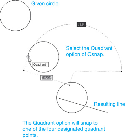
Figure 3-10
To Draw a Line to One of a Circle’s Quadrant Points
- Select the Line tool from the Draw panel.
Command: _line Specify first point:
- Select a start point for the line.
Specify next point or [Undo]:
- Select the Quadrant tool from the Osnap dialog box.
Specify next point or [Undo]: _qua of
- Select a point on the circle near the desired quadrant point.
3-10 Osnap—Perpendicular
The Perpendicular option is used to draw a line perpendicular to an existing entity. See Figure 3-11.
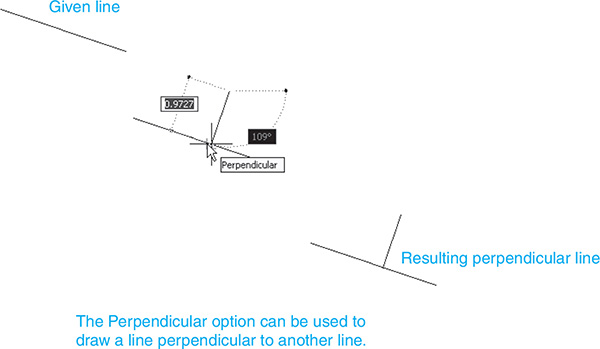
Figure 3-11
To Draw a Line Perpendicular to a Line
- Select the Line tool from the Draw panel.
Command: _line Specify first point:
- Select a start point for the line.
Specify next point or [Undo]:
- Select the Perpendicular tool on the Osnap dialog box.
Specify next point or [Undo]: _per to
- Select the line or entity that will be perpendicular to the drawn line.
3-11 Osnap—Tangent
The Tangent option is used to draw lines tangent to existing circles and arcs. See Figure 3-12.
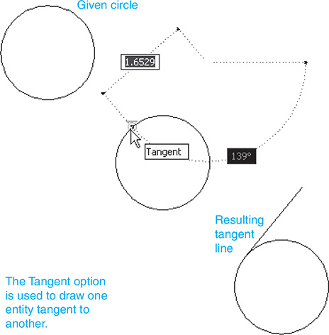
Figure 3-12
To Draw a Line Tangent to a Circle
- Select the Line tool from the Draw panel.
Command: _line Specify first point:
- Select the start point for the line.
Specify next point or [Undo]:
- Select the Tangent tool from the Osnap dialog box.
Specify next point or [Undo]: _tan to
- Select the circle.
3-12 Osnap—Nearest
The Nearest option is used to snap to the nearest available point on an existing entity. See Figure 3-13.
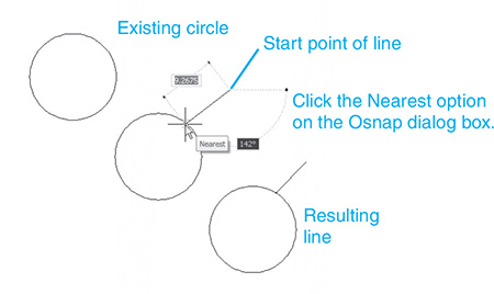
Figure 3-13
To Draw a Line from a Point to the Nearest Selected Point on an Existing Line
- Select the Line tool from the Draw panel.
Command: _line Specify first point:
- Select a start point for the line.
Specify next point or [Undo]:
- Select the Nearest tool from the Osnap dialog box.
Specify next point or [Undo]: _nea to
- Select the existing line.
The existing line need be only within the rectangular box on the cursor. The line endpoint will be snapped to the nearest available point on the line.
3-13 Sample Problem SP3-1
Redraw the object shown in Figure 3-14. Do not include dimensions. Use Osnap commands whenever possible.

Figure 3-14
- Create a new drawing called SP3-1.
- Drawing setup:
Limits: lower left = <0.0000,0.0000>
Limits: upper right = 297,210
Zoom All
Grid = 10
Snap = 5
- Draw an 83.9 × 56.5 rectangle. Use dynamic input values to draw the rectangle’s edge lines. See Figure 3-15.
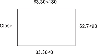
Figure 3-15
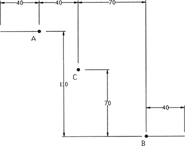
- Draw line A–B–C. Point A is a grid snap point, so it may be selected directly. Point B is selected by using Osnap Midpoint, and point C is selected by using Osnap Endpoint (or Intersection). See Figure 3-16.

Figure 3-16
- Draw line D–E–F by using Endpoint, Midpoint, and Endpoint, respectively.
 Draw line B–E by using Intersection. See Figure 3-17.
Figure 3-17
 Draw line G–H by using Midpoint.
 Save the drawing if desired.
3-14 Sample Problem SP3-2
Redraw the object shown in Figure 3-18. Do not include dimensions.
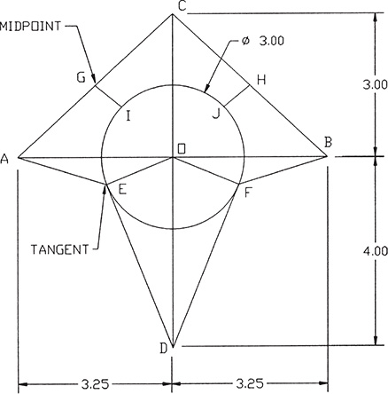
Figure 3-18
- Create a new drawing called SP3-2.
- Drawing setup:
Limits: Accept the default values
Grid = .50
Snap = .25
- Draw lines A–B, C–D, A–C, and C–B. The endpoint of each of these lines is located on a grid snap point, so the points may be selected directly.
- Draw circle O. See Figure 3-19. Respond to the center point prompt by selecting Intersection from the Osnap pop-up menu.

Figure 3-19
- Draw lines G–I and H–J, using Midpoint and Nearest. See Figure 3-20.
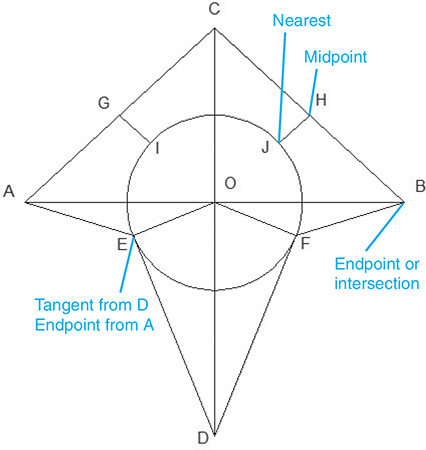
Figure 3-20
- Draw lines D–E and D–F, using Tangent. Draw lines A–E and B–F, using Endpoint. Points A, B, and D are grid snap points and also are endpoints.
- Save the drawing if desired.
3-15 Grips
The Grips function is used to quickly identify and lock onto convenient points on entities such as the endpoints of lines or the center point of a circle. Figure 3-21 shows some examples of grip points.

Figure 3-21
Grips are helpful when using some Modify commands. For example, if a line is to be rotated about its center point, a grip can be used to first identify the line’s center point (pickbox) and then lock onto it as the center point (base point) for the rotation. The center point of a circle can be used to move the circle to a new location.
To Turn the Grips Function Off
By default, the Grips command is automatically on. The Grips command may be turned off as follows:
- Type Grips in response to a command prompt.
Enter new value for GRIPS <1>:
There are two possible values: 1 and 0. The 1 value turns the Grips command on. The 0 value turns the Grips command off. See Figure 3-22.

Figure 3-22
- Type 0; press Enter.
The Grips command is now off.
To Access the Grips Dialog Box
- Grip an existing line—that is, place the cursor on the line, and press the left mouse button.
A line is gripped when a command prompt is displayed and no other command sequence is active.
- Click on one of the grip points.
In this example, the lower endpoint was selected.
<Stretch to point>/Basepoint/Copy/Undo/eXit:
- Right-click the mouse.
The Grips dialog box will appear. See Figure 3-23.
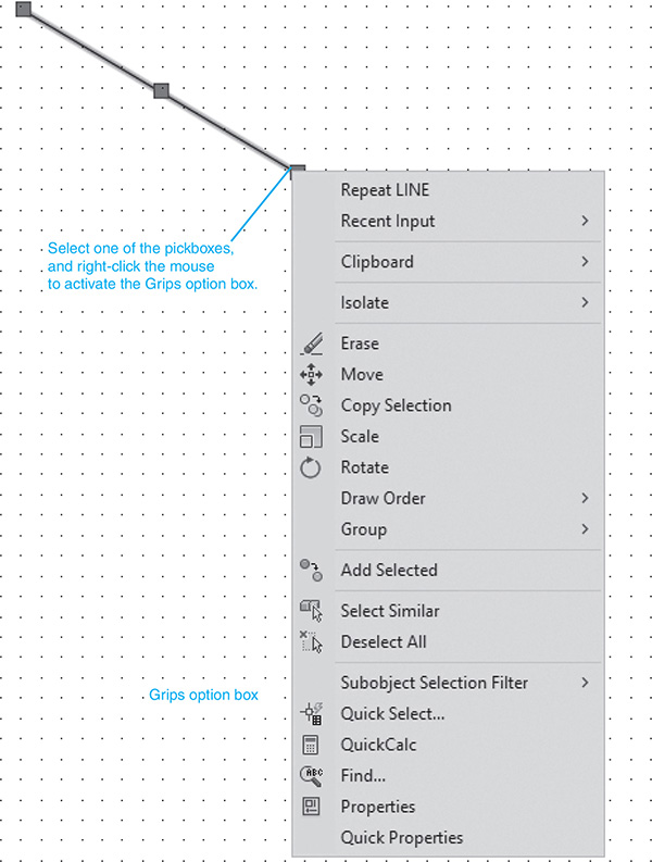
Figure 3-23
3-16 Grips—Extend
To Extend the Length of a Line (See Figure 3-24.)

Figure 3-24
Given a line, extend it 1.25 inches.
- Draw an angled line as shown; then draw a circle of radius 1.25 centered on one of the line’s endpoints.
- Press the <Esc> key to ensure a command prompt.
- Select the line.
Blue pickboxes should appear at the two endpoints and at the midpoint.
- Select the endpoint that also serves as the circle’s center point.
The blue pickbox should change to a solid-red square box.
- Press the right mouse button, and select the Stretch option from the Grips menu.
**STRETCH**
Specify stretch point or [Base point Copy Undo eXit]:
Stretch the endpoint of the line to the edge of the 1.25 circle by accessing the Osnap menu (press the <Ctrl> key and right mouse button) and selecting the Nearest option.
- Select a point on the circle that aligns the line through the three grip points; then press the left button.
- Erase the circle.
3-17 Grips—Move
To Move an Object by Using Grips (See Figure 3-25.)

Figure 3-25
Move the given circle to a new location on the drawing.
- Press the <Esc> key to ensure a command prompt.
- Select any point on the circle.
Blue pickboxes should appear at circle O’s center point and at each of the quadrant points.
- Select the circle’s center point.
The center point pickbox should change to a solid-red square box.
**STRETCH**
Specify stretch point or [Base point Copy Undo eXit]:
- Move the circle to a new location, and press the left mouse button.
The circle’s new location can be located by using dynamic input.
3-18 Grips—Rotate
To Rotate an Object by Using Grips (See Figure 3-26.)
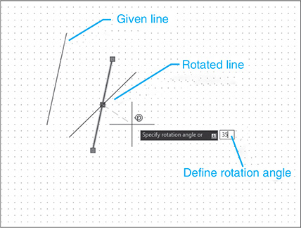
Figure 3-26
Given a line, rotate it 35° about its midpoint.
- Press the <Esc> key to ensure a command prompt.
- Select the line.
Blue pickboxes should appear at the line’s two endpoints and at its midpoint.
- Select the line’s midpoint.
The blue pickbox at the midpoint should change to a solid-red square box.
- Press the right mouse button; then select Rotate from the Grips dialog box.
**ROTATE**
Specify rotation angle or [Base point Copy Undo eXit]:
- Type 35; press Enter.
The value 35 will appear in the dynamic input box.
3-19 Grips—Scale
To Change the Scale of an Object (See Figure 3-27.)

Figure 3-27
Given an object, reduce it to half of its original size.
- Press the <Esc> key to ensure a command prompt.
- Select the object by first windowing it, then pressing the left mouse button.
Blue pickboxes should appear all around the object.
- Select any one of the pickboxes.
The selected pickbox should change to a solid-red square box.
- Press the right mouse button to activate the Grips options box.
- Select Scale from the menu.
**SCALE**
Specify scale factor or [Base point Copy Undo Reference eXit]:
- Type .5; press Enter.
Figure 3-27 also shows the same object scaled to twice its original size—that is, a scale factor of 2.
3-20 Grips—Mirror
To Mirror an Object (See Figure 3-28.)
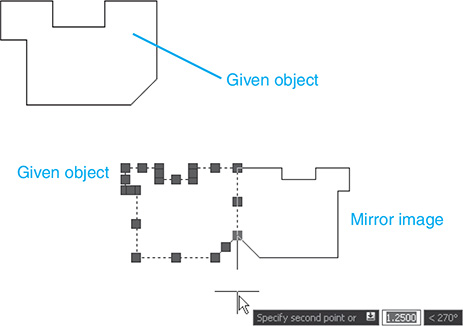
Figure 3-28
Given an object, draw a mirror image of the object.
- Press the <Esc> key to ensure a command prompt.
- Window the object; then press the left mouse button.
Blue pickboxes should appear at each corner intersection of the hexagon.
- Select the upper right pickbox.
The selected pickbox should change to a solid-red square box.
- Press the right mouse button to activate the Grips options box.
- Select the Mirror option.
**MIRROR**
Specify second point or [Base point Copy Undo eXit]:
- Select the pickbox vertically below the selected upper right pickbox.
- Press the <Esc> key twice to fix the mirrored object.
3-21 Blocks
Blocks are groups of entities saved as a single unit. Blocks are used to save shapes and groups of shapes that are used frequently when creating drawings. Once created, blocks can be inserted into the drawings, thereby saving drawing time.
The Block tools are located in the Block and Block Definition panels under the Insert tab. Blocks are first created by using the Block tool. They are then saved and, when needed, inserted into a drawing by use of the Insert tool. Blocks can be edited after they are created. See Figure 3-29.
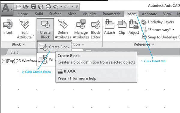
Figure 3-29
To Create a Block
Figure 3-30 shows an object. A block can be made from this existing drawing as follows:

Figure 3-30
- Select the Create Block tool from the Block Definition panel.
The Block Definition dialog box appears. See Figure 3-30.
- Click the Select objects box.
Select objects:
- Window the object; press Enter.
The Block Definition dialog box will reappear.
- Type SHAPE in the Name box.
Block names may contain up to 31 characters.
- Click the Pick point box.
- Define the centerline insertion as the base point for the block.
The Block Definition dialog box will reappear. Osnap may be used to locate an insertion point. The values listed in the Block Definition dialog box are XYZ values relative to the current origin.
The insertion base point will be a point on the object that will align with the screen cursor during the block insertion process.
In this example, the Osnap tool was used to define the intersection of the shape’s centerlines as the insertion point.
- Select the OK box.
To Insert a Block
- Click the Insert tab and select Insert from the Block panel.
- Click the Recent Blocks option. See Figure 3-31.

Figure 3-31
A visual listing of recently created blocks will appear. See Figure 3-32.
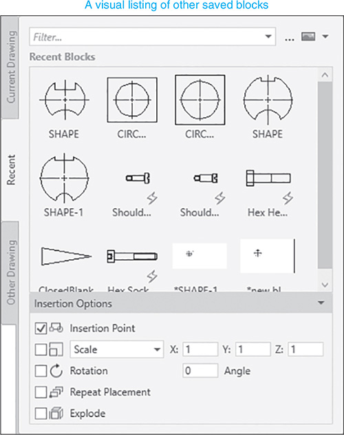
Figure 3-32
- Drag and drop the block onto the screen
The Shape block will appear on the screen with its insertion point aligned with the cursor.
- Select the insertion point and click the mouse.
The Block will appear drawn to original scale it was created. The scale and angle of rotation can be edited.
The default scale factor is 1. This means that if you accept the default value by pressing Enter, the shape will be redrawn at its original size.
To Change the Scale of a Block
- Select Insert from the Block panel.
- Select the SHAPE block.
Specify insertion point or [Basepoint Scale X Y Z Rotate]:
- Type S; press Enter.
Specify scale factor for XYZ axes:
- Type 2; press Enter.
Specify insertion point:
- Select a point.
The Rotation option is used to rotate a block about its insertion point. AutoCAD assumes that a horizontal line to the right of the insertion point is 0° and that counterclockwise is the positive angular direction.
The block is now part of the drawing; however, the block in its present form may not be edited. Blocks are treated as a single entity and not as individual lines. You can verify this by trying to erase any one of the lines in the block. The entire object will be erased. The object can be returned to the screen by clicking the Undo tool. A block must first be exploded before it can be edited.
To Explode a Block
- Select the Explode tool from the Modify panel.
Command: _explode
Select objects:
- Window the entire object.
Select objects:
- Press Enter.
The object is now exploded and can be edited. There is no visible change in the block on the screen, but there will be a short blink after the Explode command is executed.
3-22 Working with Blocks
Figure 3-33 shows a resistor circuit. It was created from an existing block called RESISTOR. The drawing used Decimal units with a grid set to 0.5 and a snap set to 0.25. The default drawing limits were accepted. The procedure is as follows:
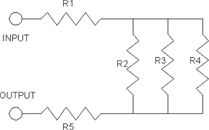
Figure 3-33
To Insert Blocks at Different Angles
- Select Insert from the Draw panel.
The Insert dialog box will appear.
- Select the cascade menu on the right side of the Name box.
- Figure 3-34 shows RESISTOR in the Name box. Select the RESISTOR block.
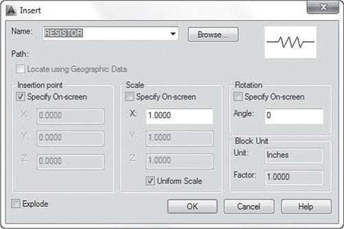
Figure 3-34
- Select OK to return to the drawing screen.
The RESISTOR block will appear attached to the crosshairs at the predefined insertion point. See Figure 3-35.
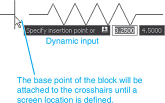
Figure 3-35
The resistor is too large for the drawing, so a reduced scale will be used to generate the appropriate size.
Specify insertion point or [Basepoint Scale X Y Z Rotate]:
- Type S; press Enter.
Specify scale factor for XYZ axes:
- Type 0.50; press Enter.
Specify insertion point:
Locate the resistor on the screen.
- Press the right mouse button, and select the Repeat Insert option.
- Select the RESISTOR block again, and set the X, Y, Z scale factors for .50.
Specify insertion point or [Scale X Y Z Rotate PScale PX PY PZ
PRotate]:
 Type R; press Enter.
Specify rotation angle:
 Type 90; press Enter.
Specify insertion point:
 Select an insertion point as shown in Figure 3-36.
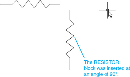
Figure 3-36
Your screen should look like Figure 3-36.
 Use the Copy command (Modify panel) to add the additional required resistors. See Figure 3-37.
Figure 3-37
 Use the Line command (Draw panel) to draw the required lines.
 Select the Circle command (Draw panel), and draw a circle of diameter 0.250.
 Use the Copy command (Modify panel) to create a second circle.
 Use the Move command to position the circles so that they touch the edges of the two open circles.
 Use the Dtext command to add the appropriate text.
The drawing should now look like the diagram presented in Figure 3-33.
To Insert Blocks with Different Scale Factors
Figure 3-38 shows four different-sized threads, all created from the same block. The block labeled A used the default scale factor of 1, so it is exactly the same size as the original drawing used to create the block. The block labeled B was created with an X scale factor equal to 1, and a Y scale factor equal to 2. The procedure is as follows:

Figure 3-38
- Select the Insert tool from the Draw panel.
- Select the THREAD block.
The THREAD block is not an AutoCAD creation. THREAD was created specifically for this example.
Specify insertion point or [Scale X Y Z Rotate PScale PX PY PZ PRotate]:
- Type X; press Enter.
Specify X scale factor:
- Type 1; press Enter.
Specify insertion point:
- Type Y; press Enter.
Specify Y scale factor:
- Type 2; press Enter.
Specify insertion point:
- Specify a point.
The thread labeled C has an X scale factor of 0.75 and a Y scale factor of 1.25. The thread labeled D has an X scale factor of 0.5, a Y scale factor of 0.75, and a rotation angle of 180°.
To Use the Insert Dialog Box to Change the Shape of a Block
The D thread scale factors and rotation angle were defined through the Insert dialog box. The procedure is as follows:
- Select the Insert tool.
The Insert dialog box will appear. See Figure 3-39.
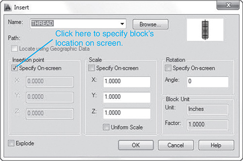
Figure 3-39
- Click the box to the left of the words Specify On-screen.
The click should remove the check mark in the box, indicating that the option has been turned off. When the check mark has been removed, the options labeled Insertion point, Scale, and Rotation should change from gray to black in the dialog box.
- Place the cursor arrow inside the X Scale box, backspace to remove the existing value, and type .50.
- Change the Y Scale factor to .75.
- Change the Angle to 180.
See Figure 3-39. The insertion point was defined on screen.
To Combine Blocks
Figure 3-40 shows a hex head screw that was created from two blocks. The threaded portion of the screw was created first; then the head portion was added. Note in Figure 3-40 that when the hex head block was created, the insertion point was deliberately selected so that it could easily be aligned with the centerline and the top surface of the thread block.

Figure 3-40
3-23 Wblock
Wblocks are blocks that can be entered into any drawing. When a block is created, it is unique to the drawing on which it was defined. This means that if you create a block on a drawing, then save and exit the drawing, the block is saved with the drawing, but cannot be used on another drawing. If you start a new drawing, the saved block will not be available.
Any block can be defined and saved, however, as a wblock. Wblocks are saved as individual drawing files and can be inserted into any drawing.
To Create a Wblock
This section shows how to create a wblock for the block called SHAPE-1 shown in Figure 3-30. A wblock may be created directly from an object shown on the screen.
- Open the SHAPE-1 drawing.
- Click the Insert tab and select the Write Block option.
The Write Block dialog box appears. See Figure 3-41.
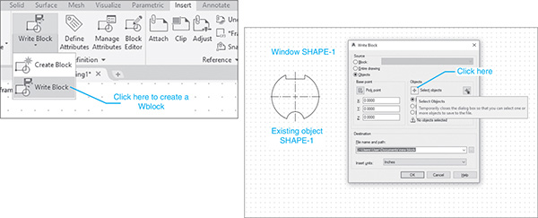
Figure 3-41
Ensure that the Objects radio button is on.
- Click the Select objects box.
The Write Block dialog box will vanish.
- Select the SHAPE; press Enter.
- Click the Pick point box.
See Figure 3-42.
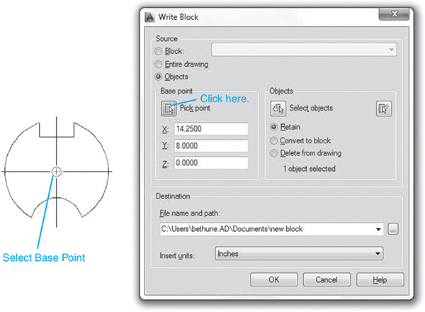
Figure 3-42
- Select the base point for the Wblock.
- Enter a new file name for the Wblock.
In this example, the name SHAPE-1 was entered. See Figure 3-43.
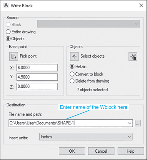
Figure 3-43
- Click OK.
To Verify that a Wblock Has Been Created
- Click the Insert tab, click the Insert tool, and click the Recent Blocks options.
The Recent box will appear. See Figure 3-44.

Figure 3-44
- Click the SHAPE-1 icon and move it onto the drawing field.
Because Wblocks are independent of a single drawing, they are saved as separate drawings. Figure 3-44 also shows a listing for SHAPE-1 in the Document files.
To Change the Size of a Wblock
- Select the Insert tab, click the Insert tool, and click the Recent Blocks options.
The scale of the Wblock is changed in the Insert Options box.
- Click the SHAPE-1 icon and move it onto the drawing field.
In this example, the x and y values were set at 2.
- Select OK.
See Figure 3-45.
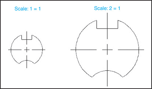
Figure 3-45
3-24 Layers
A layer is like a clear piece of paper that you can lay directly over the drawing. You can draw on the layer and see through it to the original drawing. Layers can be made invisible, and information can be transferred between layers.
In the example shown, a series of layers will be created, and then a group of lines will be moved from the initial 0 layer to the other layers.
The Layers panel is located under the Home tab. See Figure 3-46. There are five indicators shown on the Layers panel that serve to indicate the status of some of the layer options. For example, the open padlock indicates that layer 0 is open. If the padlock were closed, it would indicate that the layer was locked.

Figure 3-46
To Create New Layers
This exercise will create two new layers: Hidden and Center.
- Click the Layer Properties tool on the Layers panel under the Home tab.
The Layer Properties Manager dialog box will appear along the left side of the screen. See Figure 3-47. You may have to extend the box to the right to see all its contents.
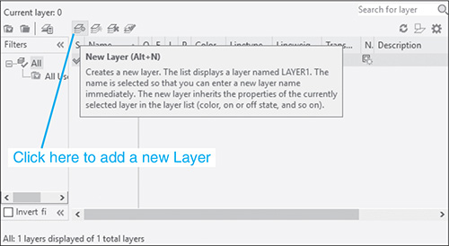
Figure 3-47
- Click the New Layer box.
A new layer listing will appear with the name Layer1. See Figure 3-48.
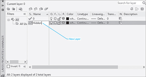
Figure 3-48
- Type Hidden in place of the Layer1 name.
The name Hidden should appear under the 0 layer heading in the Name column.
- Click the New Layer box again, and add another new layer named Center.
The name Center will appear in the Name column. There are now three layers associated with the drawing. See Figure 3-49. The 0 layer is the current layer, as indicated by the 0 to the right of the Current layer box.
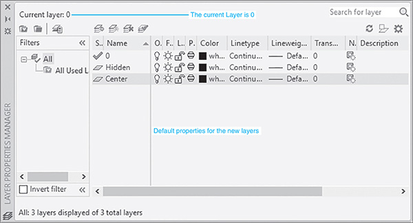
Figure 3-49
To Change the Color and Linetype of a Layer
- Scroll across the Layer Properties Manager to the Color heading.
- Locate the cursor on the wh … notation on the Hidden layer line and click the mouse.
The word white will appear, indicating that the layer’s color is white. See Figure 3-50.
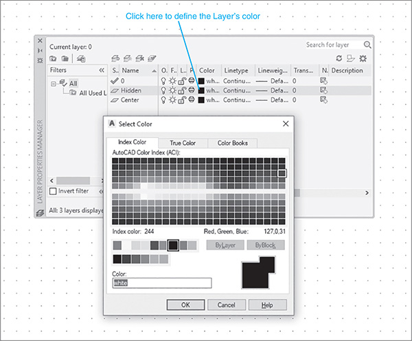
Figure 3-50
The Select Color dialog box will appear. See Figure 3-51.
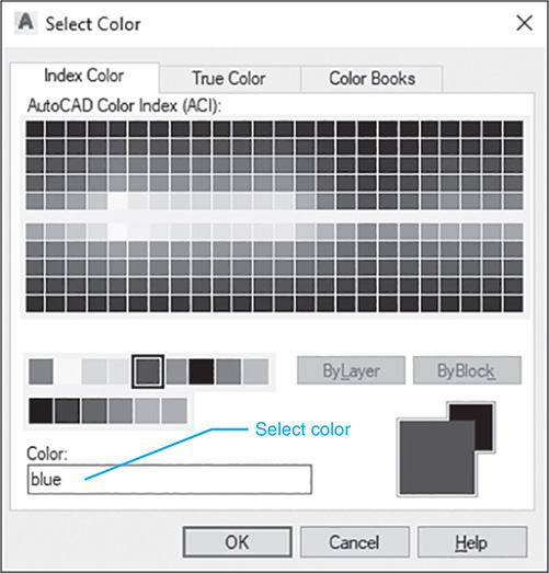
Figure 3-51
- Select the color blue; then click OK.
All lines drawn on the Hidden layer will now be blue. The color box for the Hidden layer will be blue.
- Click the word Continuous on the Hidden layer line under the Linetype heading.
The Select Linetype dialog box will change. See Figure 3-52.

Figure 3-52
- Click the Load button.
The Load or Reload Linetypes dialog box will appear. See Figure 3-53.

Figure 3-53
- Scroll down the Linetype list, and select the HIDDEN pattern by clicking on the pattern preview. See Figure 3-54.

Figure 3-54
- Click OK.
- Select the Center layer line.
The line will be highlighted.
- Change the Center layer’s line color to red and its linetype to CENTER.
The Layer Properties Manager dialog box should look like Figure 3-55.

Figure 3-55
To remove the Layer Properties Manager box from the screen, locate the cursor on an open portion of the drawing screen and click the mouse.
To Draw on Different Layers
Only the layer designated as the current layer may be worked on, even though other layers may be visible. There are three ways to make a layer the current layer. See Figure 3-56.
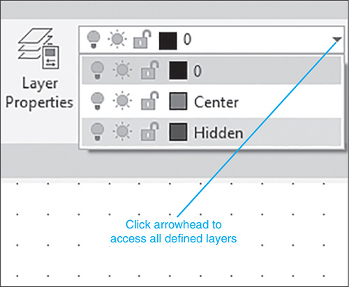
Figure 3-56
- Use the Layer located on the Layers panel under the Home tab. Click a layer’s name. The layer will become the current layer. The current layer is the name displayed in the Layer control box after the cascade disappears.
- Use the Layer Properties Manager tool to access the Layer Properties Manager dialog box. Click on a layer name, click the current box, and then click OK. The layer name will appear in the Layer control box, indicating that it is the current layer.
- Use the Make Object’s Layer Current tool by clicking an entity on the screen. The entity’s layer will become the current layer.
Once a current layer has been established, objects may be drawn and modified on that layer.
To Change Layers
An object may be drawn on one layer and moved to another layer. This feature is helpful when designing; for example, an original layout may be created in a single layer and then lines may be transferred to different layers as needed. As a line changes layers, it assumes the color and linetype of the new layer. Figure 3-57 shows a circle and a line drawn on the 0 layer. Change the line to a centerline and the circle to a hidden line by moving the objects to the appropriate layer.
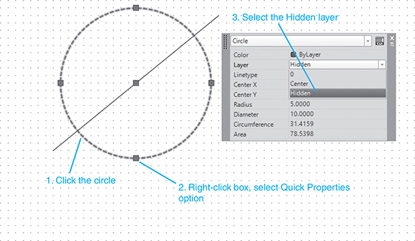
Figure 3-57
- Click the circle, and right-click one of the grip pickboxes. Then click the Quick Properties option.
The Circle Properties dialog box will appear.
- Click the Layer line, and scroll down and click the Hidden option.
The circle’s color will turn blue, and the linetype will change to a hidden pattern.
- Transfer the line to the Center layer by the same procedure.
Figure 3-58 shows the results of the layer changes.

Figure 3-58
To Change the Scale of a Linetype
Figure 3-59 shows two parallel lines drawn on the Hidden layer.

Figure 3-59
- Click the lower line.
The grip points will appear on the line.
- Right-click one of the pick points.
A dialog box will appear.
- Click the Properties option.
The Properties dialog box will appear. See Figure 3-60.

Figure 3-60
- Change the Linetype scale to 3.0000.
- Close the Properties dialog box by clicking the X in the upper left corner of the box, and press the <Esc> key.
Figure 3-61 shows the resulting changes in the lower line. The new line has a different linetype scale and therefore different spacing.
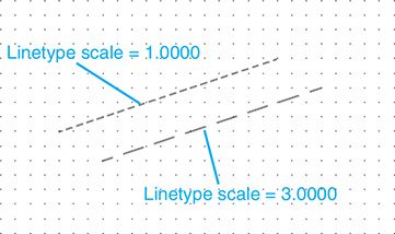
Figure 3-61
To Use the Match Tool
Figure 3-62 shows two lines. The upper line is on the Hidden layer, and the lower line is on the 0 layer. The Match tool is used to change the layer of the lower line (0 layer) to the layer of another object (Center layer).

Figure 3-62
- Click the Match tool.
Select objects to change:
Select objects:
- Click the line on the 0 layer, the lower line.
Select object:
- Right-click the mouse.
Select object on destination layer or [Name]:
- Click the line on the Hidden line, the upper line.
The lines are both on the Hidden layer.
To Turn Layers Off
- Select the Layer Properties tool.
A list of current layers will cascade from the box.
- Click the lightbulb icon on the Center layer.
The lightbulb icon will change from yellow to blue, indicating that the layer is off.
3-25 Attributes
Attributes are sections of text added to a block that prompt the drawer to add information to the drawing. For example, a title block may have an attribute that prompts the illustrator to add the date to the title block as it is inserted into a drawing. Attributes can be found on the Attributes panel on the Insert tab.
To Add an Attribute to a Block
Figure 3-63 shows a block named SHAPE-1. It was added to a new drawing by using the Block command on the Insert panel. This example will add attributes that request information about the product’s part number, material, quantity, and finish.
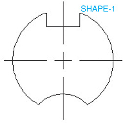
Figure 3-63
- Access the Block Definition panel under the Insert tab, and click the Define Attributes tool.
The Attribute tools will appear.
- The Attribute Definition dialog box will appear. See Figure 3-64.
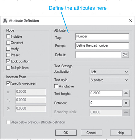
Figure 3-64
- Type Number in the Tag box.
A tag is the name of an attribute and is used for filing and reference purposes. Tag names must be one word with no spaces.
- Select the Prompt box, and type Define the part number.
The prompt line will eventually appear at the bottom of the screen when a block containing an attribute is inserted into a drawing. If you do not define a prompt, the tag name will be used as a prompt.
- Leave the Default box empty.
The Value box entry will be the default value if none is entered when the prompt appears. Based on the defined prompt and value inputs, the following prompt line will appear when the attribute is combined with a block:
Define the part number <>:
- Select Specify on-screen; click OK.
The drawing will appear with crosshairs. Select a location for the attribute tag by moving the crosshairs; then press the left mouse button.
Figure 3-65 shows the attribute tag applied to a drawing. Figures 3-66 and 67 show three more Attribute Definition dialog boxes. Note that the Align below previous attribute definition box is turned on by clicking the box. Figure 3-68 shows the resulting drawing.
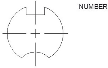
Figure 3-65

Figure 3-66
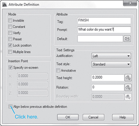
Figure 3-67
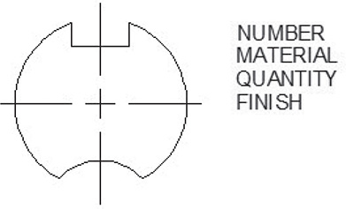
Figure 3-68
To Create a New Block that Includes Attributes
- Select the Create tool from the Block panel.
The Block Attribute Manager dialog box will appear.
- Name the new block SHAPE-2.
- Select a base point.
In this example, the center point was selected.
- Select the object by windowing the block and all the attribute tags.
- Select OK.
Verify that the attributes are correct by accessing the Edit Attribute dialog box via the Block Attribute Manager. If all entries are correct, select OK.
See Figure 3-69.

Figure 3-69
Figure 3-70 shows the resulting block.

Figure 3-70
To Insert an Existing Block with Attributes
- Select the Insert tool on the Draw panel.
The Insert dialog box will appear. See Figure 3-71.

Figure 3-71
- Select SHAPE-2, and then click OK.
Specify the insertion point or [Scale X Y Z Rotate PScale PX PY PZ PRotate]:
- Select an insertion point.
Enter attribute values
What material is needed? <Steel>:
- Press Enter.
What color do you want? <Black>:
- Select a different color by typing Blue; press Enter.
How many are needed?
- Type 4; press Enter.
What material is needed?
- Press Enter.
(The default value Steel is acceptable.)
Define the part number <>:
- Type BU-AM311; press Enter.
Figure 3-72 shows the resulting drawing.
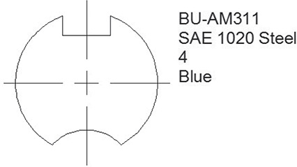
Figure 3-72
To Edit an Existing Attribute
Once a block has been created that includes attributes, it may be edited by using the Manage Attributes command. The procedure is as follows. The block to be edited must be on the drawing screen.
- Click the Block Attributes Manager tool on the Block panel.
The Block Attribute Manager dialog box will appear. See Figure 3-73.
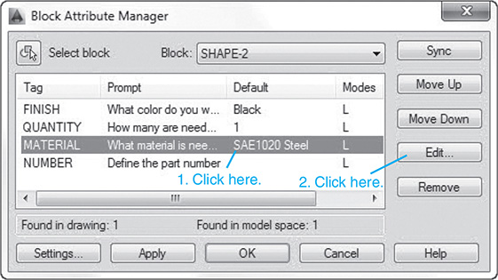
Figure 3-73
- Click the Material line; then click the Edit box.
The Edit Attribute dialog box will appear. See Figure 3-74.

Figure 3-74
- Replace the words SAE 1020 Steel with the word Aluminum.
- Click OK.
Figure 3-75 shows the resulting changes.

Figure 3-75
3-26 Title Blocks with Attributes
Figure 3-76 shows a title block that has been saved as a block. It would be helpful to add attributes to the block so that when it is called up to a drawing, the drawer will be prompted to enter the required information.

Figure 3-76
Note that text may be added to an AutoCAD template by use of the Mtext command. Create the desired text, and use the Move command to position it within the title block. The title block shown in Figure 3-76 was custom drawn for a special application.
Figures 3-77, 3-78, 3-79, 3-80, and 3-81 show the five Attribute Definition dialog boxes used to define the title block attributes. Note that the text height in Figures 3-77 through 3-81 may be varied if desired. Also note that no attribute defaults were assigned. This means that the space on the drawing will be left blank if no prompt value is entered. Figure 3-82 shows the resulting title block with the attribute tags in place.
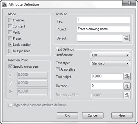
Figure 3-77
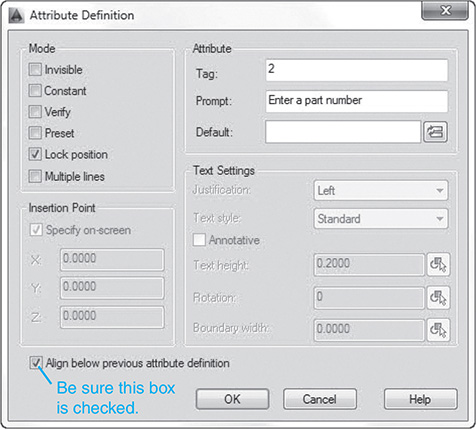
Figure 3-78

Figure 3-79
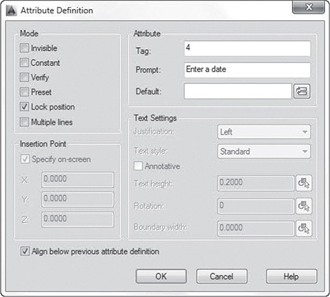
Figure 3-80
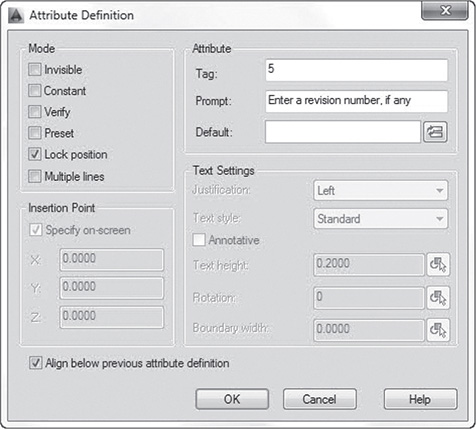
Figure 3-81

Figure 3-82
The new block with attributes was saved as TITLE-A by using the Block command. It can now be saved as a wblock and used on future drawings. Figure 3-83 shows a possible title block created from the TITLE-A block.

Figure 3-83
3-27 Edit Polyline
The Edit Polyline tool, on the Modify panel under the Home tab, is used to change the shape of a given polyline. In the example shown in Figure 3-84, the Edit Polyline command was used to create a spline from a given polyline. The Edit Polyline tool is discussed further in Section 16-17.

Figure 3-84
To Create a Spline from a Given Polyline
- Draw a polyline, using the Polyline tool on the Draw panel.
- Select the Edit Polyline tool from the Modify panel.
Command: _pedit Select polyline:
- Select the polyline.
Select an option [Close Join Width Edit vertex Fit Spline Decurve
Ltype gen Reverse Undo]:
- Select the Spline option.
Figure 3-84 shows the edited polyline.
3-28 Edit Spline
The Edit Spline tool, found on the Modify panel under the Home tab, is used to change the shape of a given spline.
To Edit a Spline
- Select the Edit Spline tool from the Modify panel.
Command: _splinedit
Select spline:
- Select the given spline.
A series of squares will appear on the screen. See Figure 3-85. These squares are the original data points used to define the spline. In this example, one of the points will be moved.
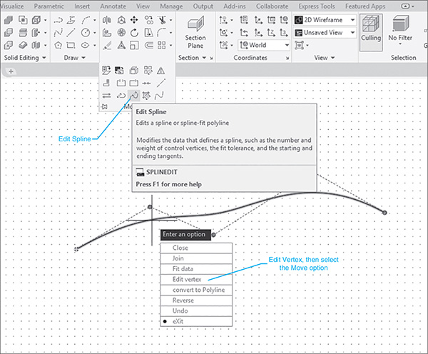
Figure 3-85
    Enter an option [Close Join Fit data Edit vertex convert to Polyline
Reverse Undo eXit]<exit>:
- Select the Edit vertex option; press Enter.
    Enter a vertex editing option [Add Delete Elevate order and Kink Move
Weight eXit] <exit>:
- Select the Move option; press Enter.
The first square data point will change colors, and a rubber-band-type line will extend from the point. An x will appear within the point. See Figure 3-86.
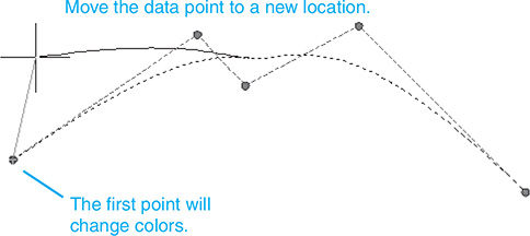
Figure 3-86
- Select a new location for the point, and click the mouse; then right-click the mouse, and select the eXit option.
Figure 3-87 shows the edited spline. The chosen location will become the new location for the first point. If a point other than the first point needs to be moved, press Enter when the X appears, and the Edit command will advance to the next point. Every time the Enter key is pressed, the Edit command will advance to the next point. Only the X option will allow you to exit the command sequence.
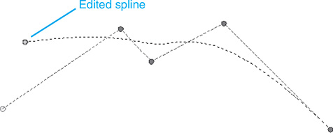
Figure 3-87
3-29 Edit Text
Figure 3-88 shows a line of text that contains a typing error. When the word worf was typed, the <f> key was struck by mistake.

Figure 3-88
To Change Existing Text
- Click the existing text. See Figure 3-89.

Figure 3-89
Blue indicator marks will appear.
- Right-click the mouse, and select the Mtext Edit . . . option.
The Multitext screen will appear.
- Edit the word; click the mouse. See Figure 3-90.

Figure 3-90
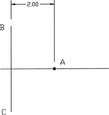
3-30 Constructing the Bisector of an Angle—Method I
Given angle A–O–B, bisect it. See Figure 3-91.

Figure 3-91
- Select Draw, Circle.
- Draw a circle with a center point located at point O. The circle may be of any radius. This is an excellent place to take advantage of AutoCAD’s Drag mode. Move the cursor until the circle appears to be approximately the same size as that shown.
- Select Copy, Multiple to draw two more circles equal in radius to the one drawn in step 2. Locate the circles’ center points on intersections of the first circle and angle A–O–B. Use Osnap Intersection to ensure accuracy.
- Draw a line from point O to intersection C as shown. Use Osnap Intersection to ensure accuracy.
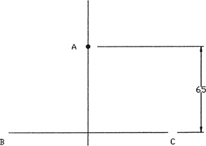
3-31 Constructing the Bisector of an Angle—Method II
Given angle A–O–B, bisect it. See Figure 3-92.

Figure 3-92
- Draw a circle with a center point located at point O. The circle may be of any radius. This is an excellent place to take advantage of AutoCAD’s Drag mode. Move the cursor until the circle appears to be approximately the same size as that shown.
- Draw a line between the intersection point created by the circle and angle A–O–B. Use Osnap Intersection to ensure accuracy.
- Draw a line between point O and the midpoint of the line. Use Osnap Midpoint to ensure accuracy.
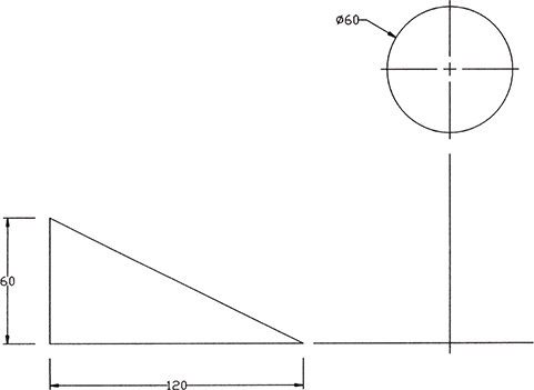
3-32 Constructing an Ogee Curve (S-Curve) with Equal Arcs
Given points B and C, construct an ogee curve between them. See Figure 3-93.

Figure 3-93
- Draw a straight line between points B and C. Use Osnap Endpoint to ensure accuracy.
- Draw lines perpendicular to lines A–B and C–D as shown.
Use Osnap Endpoint to accurately start the lines on points B and C, respectively. Use relative coordinates to draw the lines. The lines may be of any length greater than the perpendicular distance between lines A–B and C–D.
- Construct a perpendicular bisector of line B–C.
- Define the intersections of the perpendicular lines drawn in step 2 with the perpendicular bisector of B–C at points F and G.
- Draw a circle centered at point F that passes points B and E. Trim the circle by using line B–C.
- Draw a circle centered at point G that passes points C and E. Trim the circle by using line B–C.
The two arcs of steps 5 and 6 define an ogee curve by equal arcs. Figure 3-94 shows the construction of an ogee curve with unequal arcs. The construction techniques are similar to those presented previously.

Figure 3-94
3-33 Constructing a Parabola
Definition: A parabola is the loci of points such that the distances between a fixed point, the focus, and a fixed line, the directrix, are always equal.
Given a focus point A and a directrix B–C, construct a parabola. See Figure 3-95.

Figure 3-95
- Draw a line parallel to B–C so that it intersects the midpoint between line B–C and point A. Use Offset.
- Draw a circle centered about point A whose radius is equal to half of the distance between line B–C and point A.
- Offset lines and a circle 0.2 inch from the parallel line and the circle created in steps 1 and 2.
- Identify the intersections of the lines and circles created in step 3. In this example, filled circles were used to identify the points.
- Draw a polyline connecting all the intersection points.
- Use the Edit Polyline, Fit option to change the polyline to a parabolic curve.
3-34 Constructing a Hyperbola
Definition: A hyperbola is the loci of points equidistant between two fixed foci.
Given foci points F1 and F2 equidistant from a vertical line and two other vertical lines drawn through points A and B, draw a hyperbola. See Figures 3-96, 3-97, and 3-98.
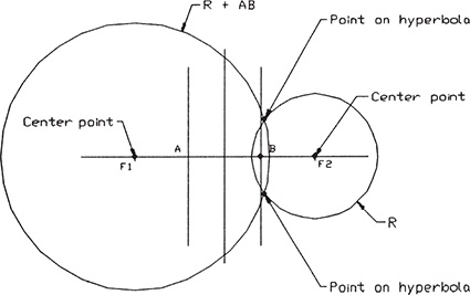
Figure 3-96
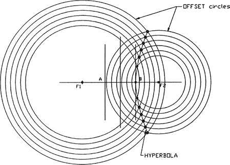
Figure 3-97
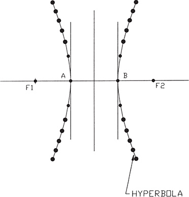
Figure 3-98
- Draw a circle of arbitrary radius, using point F2 as the center. If possible, set the drawing up so that both points F1 and F2 are on snap points. If this is not possible, draw a vertical line through point F2 so that the Osnap Intersection option may be used to locate the center accurately.
- Draw a circle centered about F2 of radius equal to the radius of the circle drawn in step 1, plus the distance between points A and B. See Figure 3-99.
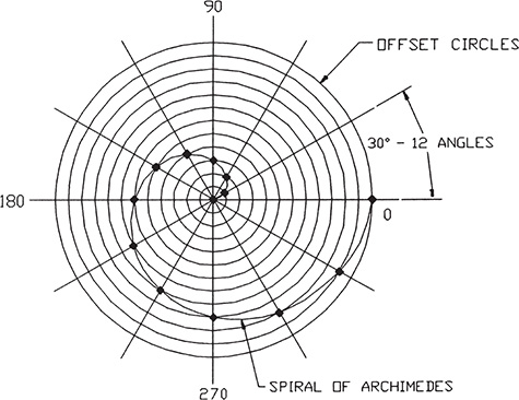
Figure 3-99
- Draw concentric circles around the circles centered about F1 and F2. The distance between all the circles should be equal. Use Offset.
- Mark the intersections between the smaller and larger circles, as shown in Figure 3-97. Use filled circles to define the points.
- Draw a polyline connecting points 1 through 12.
- Use the Edit Polyline, Fit option to draw the hyperbola.
- Use Mirror to create the opposing hyperbola. See Figure 3-98.
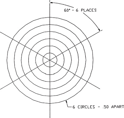
3-35 Constructing a Spiral
Construct a spiral of Archimedes. See Figure 3-99.
- Draw a set of perpendicular centerlines as shown.
- Draw 12 concentric circles about center point O. Use Offset to draw circles.
- Draw 12 equally spaced ray lines as shown. Array either the horizontal or vertical line by using the Polar Array command. Use point O as the center of rotation.
- Draw a polyline starting at point O. The second point is the intersection of the 30° ray with the first circle. Point 2 is the intersection of the 60° ray and the second circle. Continue through all 12 rays and circles.
- Use the Edit Polyline, Fit option to change the polyline to a spiral.
3-36 Constructing a Helix
Construct a helix that advances 1.875 inches every 360°. See Figure 3-100.

Figure 3-100
- Draw a vertical line 1.875 inches long and a horizontal line, as shown.
- Draw a horizontal line that can easily be divided into 12 equal spaces. The length of the horizontal line is arbitrary. Set up a grid so that the 12 equal spaces can easily be identified.
- Draw a circle as shown. Use Array, and divide the circle by 12 equally spaced rays. Use the Polar Array command with the circle’s center point as the center of rotation.
- Draw line A–B as shown. Draw 12 vertical, equally spaced lines between the horizontal line and line A–B.
- Label both the circle and the horizontal line as shown. The number of divisions must be the same for both the circle and the horizontal line.
- Draw vertical lines from the intersections of the 12 equally spaced rays and the circle’s circumference as shown in Figure 3-100. Use the Osnap Intersection option to ensure accuracy.
- Draw horizontal lines from the intersections on line A–B so that they intersect the vertical lines from step 6. Use the Osnap Intersection option to ensure accuracy.
- Mark the intersections of the lines from steps 6 and 7 as shown.
- Use a polyline to connect the horizontal and vertical intersections as shown.
- Use the Edit Polyline, Fit option to draw the helix.
3-37 Designing by Using Shape Parameters
An elementary design problem often faced by beginning designers is to create a shape based on a given set of parameters. This section presents two examples of this type of design problem.
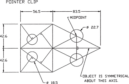
Design Problem DP3-1
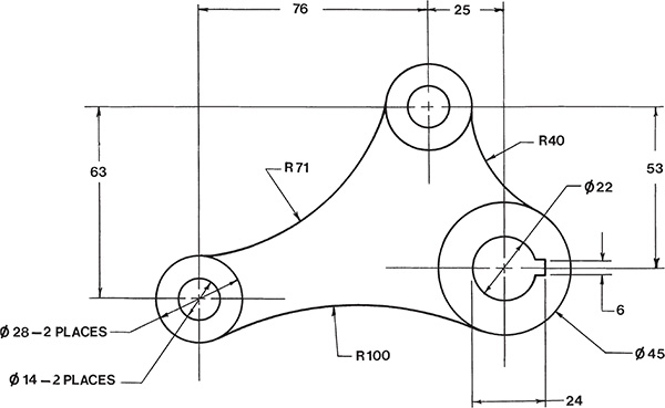
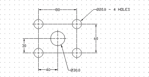
Design a shape that will support the hole pattern shown in Figure 3-101, subject to the given parameters. Design for the minimum amount of material. All dimensions are in millimeters.
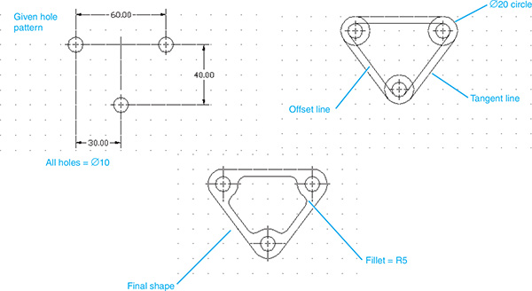
Figure 3-101
- The edge of the material may be no closer to the center of a hole than a distance equivalent to the radius of the hole.
- The minimum distance from any cutout to the edge of the part may not be less than the smallest distance calculated in step 1.
- The minimum inside radius for a cutout is R = 5 millimeters.
The solution is as follows:
- Calculate the minimum edge distances for the holes.
In this problem, the three holes are all the same diameter: 10 millimeters. Given the parameter that an edge may be no closer to the center of the hole than a distance equivalent to the size of the hole’s diameter, the distance from the outside edge of the hole to the edge of the part must be no less than 5 millimeters, or a circular shape of diameter 20 millimeters.
- Draw Ø20 circles, using the existing circle’s center point, as shown in Figure 3-101.
- Draw outside tangent lines between the Ø20 circles.
The second parameter limits the minimum edge distance to the minimum edge distance calculated in step 2, or 5 millimeters.
- Use the Offset command to draw lines 5 millimeters from the outside tangent lines drawn in step 3 to define the internal cutout.
- Use the inside radius parameter of 5 millimeters, and add fillets to the internal cutout.
- Erase any excess lines.
Figure 3-101 shows the final shape.
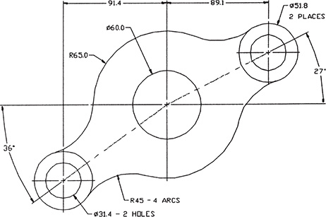
Design Problem DP3-2
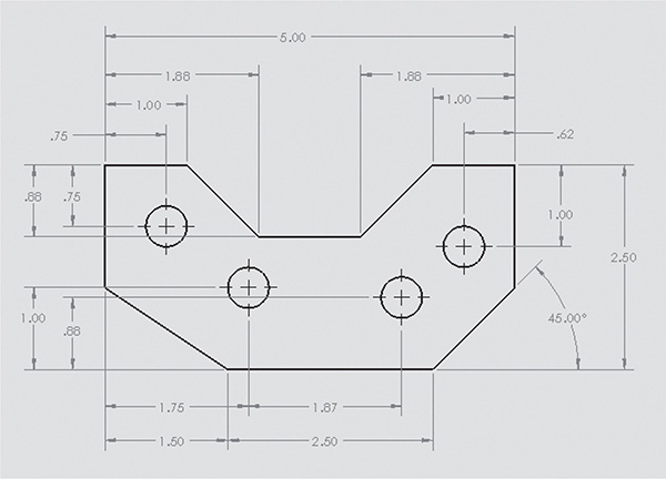
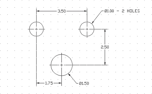
Design a shape that will support the hole pattern shown in Figure 3-102. Support the center hole with four perpendicular webs. All dimensions are in inches.
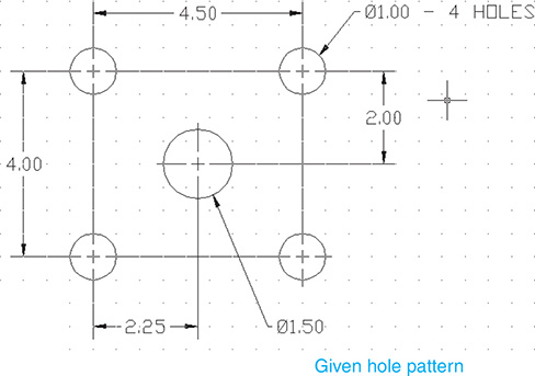
Figure 3-102
- The edge of the material may be no closer to the center of a hole than a distance equivalent to the radius of the hole.
- The minimum distance from any cutout to the edge of the part may not be less than the smallest distance calculated in step 1.
- The minimum inside radius for a cutout is R = .125 inch.
The solution is as follows:
- Calculate the minimum edge distances for the holes.
In this example, the hole diameters are 1.00 and 1.50 inches.
- Add circles of radius 2.00 and 3.00 as shown. See Figure 3-103.
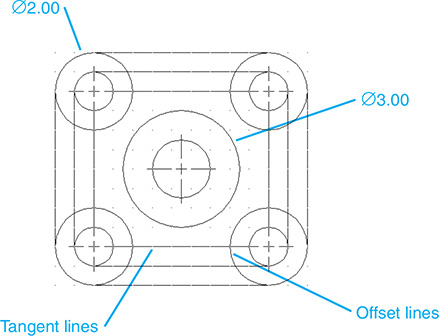
Figure 3-103
The minimum edge distance based on the Ø1.00 of the smaller hole equals 0.50 inch.
- Use the minimum edge distance, and define the inside edge of the internal cutouts.
- Use the minimum edge distance to define the four supporting webs for the center hole.
- Add the inside bend radii.
The inside bend radii were added by using the Fillet command. This will cause a portion of the internal edge to disappear. Use the Offset command again to replace the line defining the edge of the internal cutout. See Figure 3-104.

Figure 3-104
- Remove all excess lines.
See Figure 3-105.

Figure 1-105
3-38 Exercise Problems
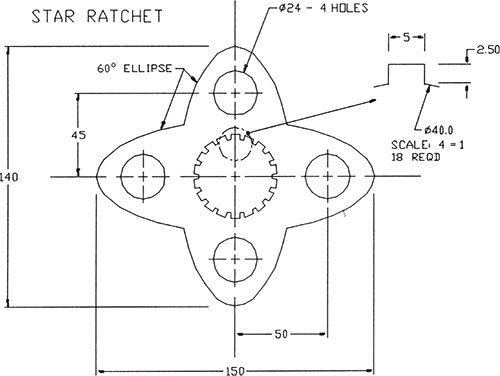
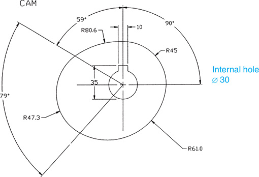
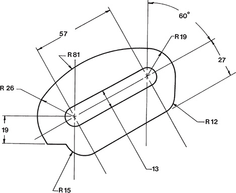
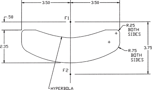
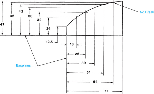
Redraw to scale the figures that follow, using the given dimensions. Do not include dimensions on the drawing.
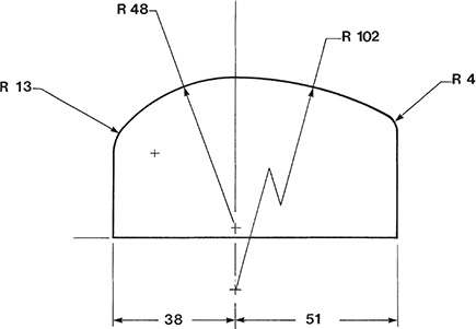
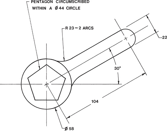
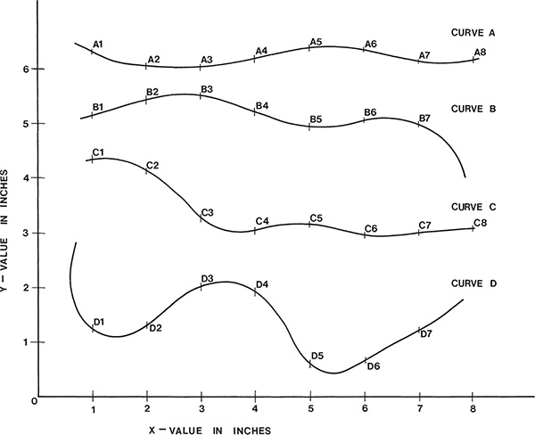
EX3-1 Inches (Hint: Use Osnap)

EX3-2 Millimeters (Hint: Use Osnap)
EX3-3 Millimeters (Hint: Use Osnap)
EX3-4 Millimeters (Hint: Use Osnap)
EX3-5
Draw a 54° angle; construct the bisector.
EX3-6
Draw an 89.33° angle; construct the bisector.
EX3-7 Inches
Given points A and B as shown next, construct an ogee curve of equal arcs.

EX3-8 Millimeters
Given points A, B, C, as shown next, construct an ogee curve that starts at point A, passes through point C, and ends at point B.
EX3-9
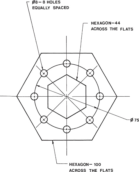
Construct a hexagon inscribed within a 3.63-inch diameter circle.
EX3-10
Construct a hexagon inscribed within a 120- millimeter diameter circle.
EX3-11 Inches
Given point A and directrix B–C as shown, construct a parabola.
EX3-12 Millimeters
Given point A and directrix B–C as shown next, construct a parabola.
EX3-13 Inches
Given foci F1 and F2 as shown next, draw a hyperbola.

EX3-14 Millimeters
Given foci F1 and F2 as shown next, draw a hyperbola.

EX3-15 Inches
Given the concentric circles and rays shown next, construct a spiral.
EX3-16 Millimeters
Given the concentric circles and rays shown next, construct a spiral.

EX3-17 Inches
Given the setup shown next, construct a helix.

EX3-18 Millimeters
Given the setup shown next, construct a helix.
EX3-19 Millimeters

EX3-20 Millimeters
EX3-21 Inches

EX3-22 Inches

EX3-23 Millimeters
EX3-24 Millimeters
EX3-25 Millimeters
EX3-26 Millimeters

EX3-27 Millimeters
EX3-28 Millimeters

EX3-29 Inches
EX3-30 Inches

EX3-31 Millimeters

EX3-32 Millimeters
EX3-33 Millimeters

EX3-34 Millimeters
EX3-35 Inches

EX3-36 Inches

EX3-37 Inches

EX3-38 Millimeters
EX3-39 Centimeters
EX3-40 Inches
EX3-41 Millimeters
EX3-42 Millimeters
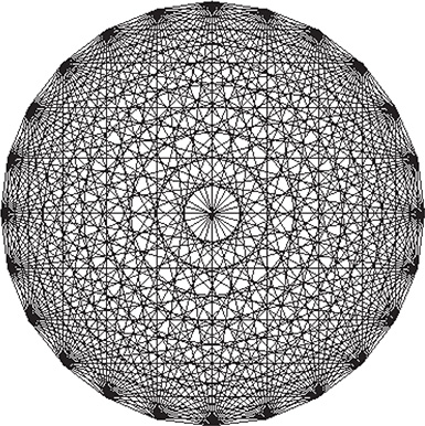
EX3-43
Draw a circle, mark off 24 equally spaced points, and then connect each point with every other point by using only straight lines.
EX3-44 Millimeters
Create a block of the drawing layout that follows.
Add the following attributes:
Tag = DATE
Prompt = Enter today’s date
Value = (leave blank)
Tag = Drawing
Prompt = Enter the drawing number
Value = (leave blank)
Tag = NAME
Prompt = Enter your name
Value = (leave blank)
Align the attribute tags on the drawing.

EX3-45 Millimeters
EX3-46 Millimeters

EX3-47 Millimeters

EX3-48 Inches

EX3-49 Millimeters

EX3-50 Inches
EX3-51 Millimeters

EX3-52 Inches
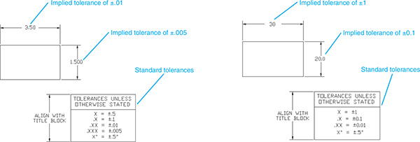
Create a block for the standard tolerance blocks shown.
EX3-53 Inches
Create a block for one of the title blocks shown. A sample completed title block is also shown.
Add attributes that will help the user complete the title block satisfactorily.

EX3-54 Inches
Create a block of the following release block:

EX3-55 Inches
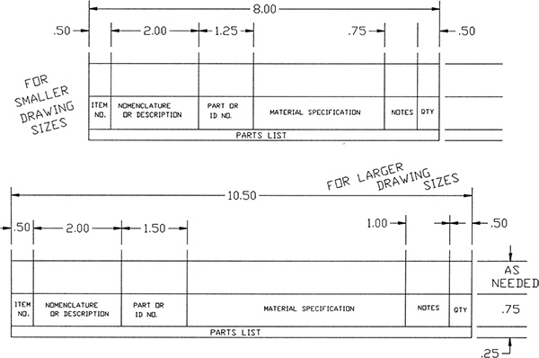
Create blocks for the parts list formats that follow. Add the appropriate attributes.
EX3-56
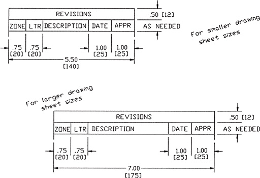
Create blocks for the given revision block formats. The dimensions within the dimension lines are inches; the dimensions within the brackets are millimeters.
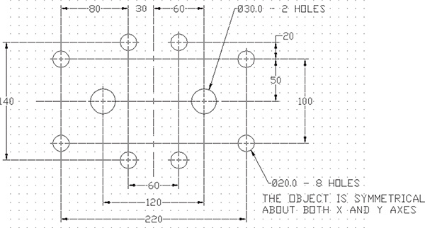
Design a shape that will support the hole patterns shown in Exercises EX3-57 through EX3-61. Design for a minimum amount of material and to satisfy the following parameters:
The edge distance of the material may be no closer to the center of a hole than a distance equal to the radius of the hole.
The minimum edge distance from any internal cutout to the edge of the part may be no less than the distance calculated in step 1.
The minimum inside radius for a cutout is 5 millimeters, or 0.125 inch.
EX3-57 Inches
EX3-58 Millimeters
EX3-59 Millimeters

EX3-60 Millimeters
EX3-61 Millimeters
