Chapter 6 Sectional Views
6-1 Introduction
Sectional views are used in technical drawing to expose internal surfaces. They serve to present additional orthographic views of surfaces that appear as hidden lines in the standard front, top, and side orthographic views.
Figure 6-1A shows an object intersected by a cutting plane. Figure 6-1B shows the same object, with its right side and the cutting plane removed. Hatch lines are drawn to represent the location on the surfaces where the cutting plane passed through solid material. Also shown are the front and right-side orthographic views and a sectional view. Note the similarity between the sectional view and the cut pictorial view.

Figure 6-1A
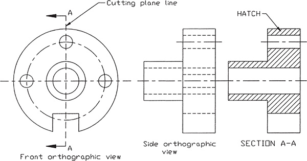
Figure 6-1B
Sectional views do not contain hidden lines, so they are used to clarify orthographic views that are difficult to understand because of excessive hidden lines. Figure 6-2 shows an object with a complex internal shape. The standard right view contains many hidden lines and is difficult to follow. Note how much easier it is to understand the object’s internal shape when it is presented as a sectional view.

Figure 6-2
Sectional views do include all lines that are directly visible. Figure 6-3 shows an object, a cutting plane line, and a sectional view taken along the cutting plane line. Surfaces that are directly visible are shown in the sectional view. For example, part of the large hole in the back left surface is, from the given sectional view’s orientation, blocked by the shorter rectangular surface. The part of the hole that appears above the blocking surface is shown; the part behind the surface is not.

Figure 6-3
Sectional views are always viewed in the direction defined by the cutting plane arrows. Any surface that is behind the cutting plane is not included in the sectional view. Sectional views are aligned and oriented relative to the cutting plane lines as a side orthographic view is to the front view. The orientation of a sectional view may be better understood by placing your right hand on the cutting plane line so that your thumb is pointing up. Move your hand to the right and place it palm down. Your thumb should now be pointing to the left. Your thumb indicates the top of the view.
Drafters and designers often refer to sectional views as “sectional cuts” or simply “cuts.” The terminology is helpful in understanding how sectional views are defined and created.
6-2 Cutting Plane Lines
Cutting plane lines are used to define the location for the sectional view’s cutting plane. An object is “cut” along a cutting plane line.
Figure 6-4 shows two linetype patterns for cutting plane lines. Either pattern is acceptable, although some companies prefer to use only one linetype for all drawings to ensure a uniform appearance in all of their drawings. The dashed-line pattern will be used throughout this book.
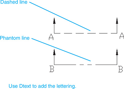
Figure 6-4
The two patterns shown in Figure 6-4 are included in AutoCAD’s linetype library as Dashed and Phantom styles. The arrow portion of the cutting plane line is created by the use of the Multileader tool, found on the Leaders panel under the Annotate tab or on the Annotation panel under the Home tab.
To Draw a Cutting Plane Line—Method I
Change a given continuous line, A–A, to a cutting plane line. See Figure 6-5. The Dashed linetype must first be added to the listing of available linetypes.
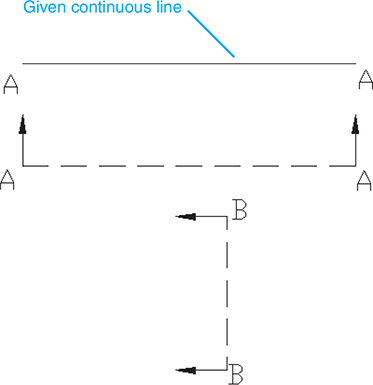
Figure 6-5
 Type the word linetype in response to a command prompt.
The Linetype Manager dialog box will appear.
 Select Load.
The Load or Reload Linetypes dialog box will appear. See Figure 6-6.

Figure 6-6
 Select Dashed and Phantom; then return to the drawing screen.
 Click line A–A.
A Properties dialog box will appear.
 Select the Linetype line on the Properties dialog box.
 Scroll down the linetype listing, and select the DASHED option.
 Close the Properties dialog box, and press the <Esc> key.
To Draw an Arrowhead
- Click the Multileader tool, and draw a leader line on the drawing screen. See Figure 6-7.

Figure 6-7
It is recommended that the leader line be either horizontal or vertical. In this example, a vertical line was drawn.
- Click the Explode tool on the Modify panel, and explode the leader line.
- Use the Erase tool from the Modify panel, and remove the short horizontal section of the line.
- Use the Move and Copy tools to create two leader lines, and position them at the ends of the dashed section line.
If necessary, use the Rotate command to align the arrowhead and line segment with the sectional line.
To Change the Size of an Arrowhead
Arrowheads used for cutting plane lines are usually drawn larger than arrowheads used for dimension lines. This serves to make them more distinctive and easier to find. The normal arrowhead scale factor is 0.19. In this example, the scale factor is 0.375.
- Select the Dimension Style Manager from the Dimensions panel under the Annotate tab.
The manager is accessed by clicking the arrow in the lower right corner of the Dimensions panel.
- Select Modify.
The Modify Dimension Style: Standard dialog box will appear. See Figure 6-8.

Figure 6-8
- Select the Symbols and Arrows tab, and use the Arrow size box within the Arrowheads portion of the dialog box to change the arrowhead’s scale factor (change to 0.3750); click OK.
- Return to the drawing screen, and use the Multileader tool to create the needed arrowheads.
The arrowhead size can also be changed by typing dimasz in response to a command prompt and typing in the new scale factor.
To Draw a Cutting Plane Line—Method II
A cutting plane can also be created by first defining a separate layer setup for cutting plane lines. The linetype will be dashed or phantom, and a color can be assigned if desired. Section 3-24 described how to create and work with layers.
To Draw Cutting Plane Lines
Cutting plane lines should extend beyond the edges of the object. See Figures 6-1, 6-2, and 6-3. A cutting plane line should extend far enough beyond the edges of the object so that there is a clear gap between the arrowhead and the edge of the object.
Note
If a cutting plane line is located directly on a centerline, it may be omitted. See Figure 6-9.

Figure 6-9
If an object is symmetrical about the centerline and only one sectional view is to be taken exactly aligned with the centerline, the cutting plane line may be omitted.
6-3 Section Lines
Section lines are used to define areas that represent where solid material has been cut in a sectional view. Section lines are evenly spaced at any inclined angle that is not parallel to any existing edge line and should be visually distinct from the continuous lines that define the boundary of the sectional view.
Figure 6-10 shows an area that includes uniform section lines evenly spaced at 45°. The other area shown in Figure 6-10 includes a 45° edge line; therefore, the section lines cannot be drawn at 45°. Lines at 135° (0° is horizontal to the right) were drawn instead.
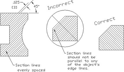
Figure 6-10
Figure 6-11 shows an object that contains edge lines at both 45° and 135°. The section lines within this area were drawn at 60°.

Figure 6-11
If two or more parts are included within the same sectional view, each part must have visually different section lines. Figure 6-12 shows a sectional view that contains two parts. Part one’s section lines were spaced 3 millimeters apart at 45°; part two’s were spaced 3 millimeters apart at 135° (–45).
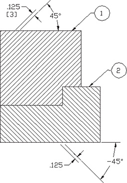
Figure 6-12
The recommended spacing for sectional lines is 0.125 inch or 3 millimeters, but smaller areas may use section lines spaced closer together than larger areas. See Figure 6-13. Section lines should never be spaced so close together as to look blurry or be so far apart that they are not clearly recognizable as section lines.
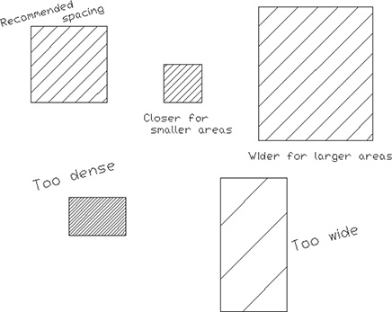
Figure 6-13
Evenly spaced sectional line patterns drawn at 45° are called general or uniform patterns; other patterns are available. Different section line patterns are used to help distinguish different materials. The different patterns allow the drawing reader to see what materials are used in a design without having to refer to the drawing’s parts list. It should be noted that not all companies use different patterns to define material differences. When you are in doubt, the general pattern is usually acceptable.
How to draw different section line patterns is explained in Section 6-4.
6-4 Hatch
Section lines are drawn in AutoCAD by use of the Hatch tool, located on the Draw panel under the Home tab. The Hatch tool offers many different hatch patterns and spacings. The general pattern of evenly spaced lines at 45° is defined as pattern ANSI31 and is the default setting for the Hatch tool.
To Hatch a Given Area
Given an area, use Hatch to draw section lines.
- Select the Hatch tool from the Draw panel.
The panels at the top of the screen will be replaced by the Hatch Creation panels. See Figure 6-14. Note that ANSI31 is the default pattern.

Figure 6-14
- Select a point within the area to be hatched, and click the mouse.
- Right-click the mouse, and select the Enter option.
The area will be hatched. See Figure 6-15.
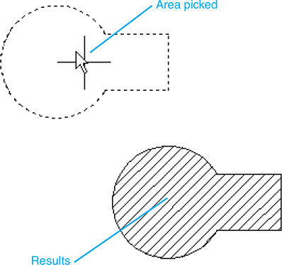
Figure 6-15
To Change Hatch Patterns
- Select the Hatch tool from the Draw panel.
The Hatch Creation panels will appear.
- Click the lowest arrow on the right side of the Pattern panel.
A selection of hatch patterns will appear. See Figure 6-16. Additional patterns can be found by scrolling down the right side of the panel.

Figure 6-16
- Select the desired pattern, and apply it as described previously.
Figure 6-17 shows three areas with four different hatch patterns applied.

Figure 6-17
To Change the Spacing and Angle of a Hatch Pattern
- Select the Hatch tool from the Draw panel.
The Hatch Creation panels will appear. See Figure 6-18. The Angle and Scale option boxes are located on the Properties panel.
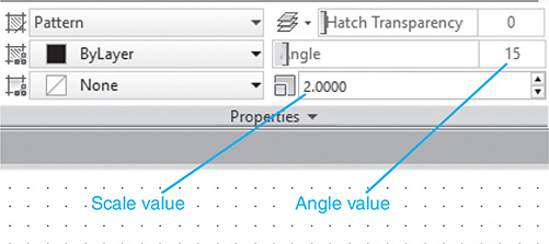
Figure 6-18
- Change the Angle to 15 and the Scale to 2.
Figure 6-19 shows a comparison between an ANSI31 pattern created with the default values of 1 and 0°, and the adjusted pattern of 2 and 15°.

Figure 6-19
6-5 Sample Problem SP6-1
Figure 6-20 shows an object with a cutting plane line. Figure 6-21 shows how a front view and a sectional view of the object are created.
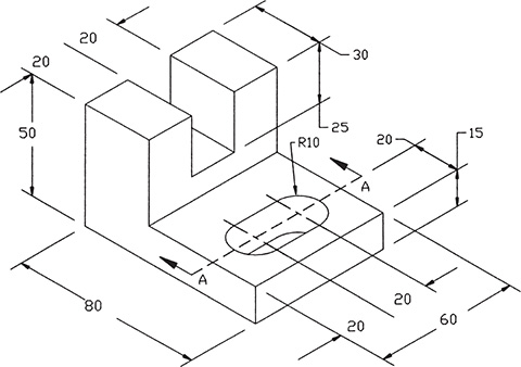
Figure 6-20
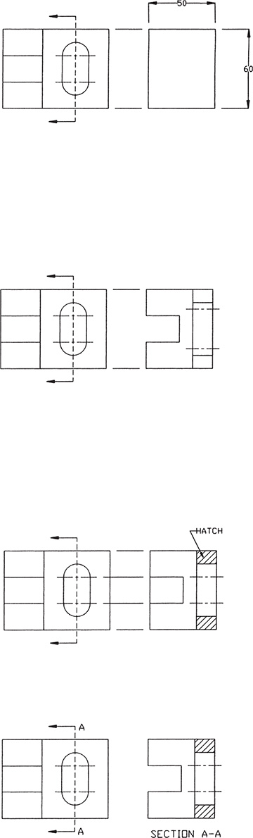
Figure 6-21
- Draw the front orthographic view of the object, and lay out the height and width of the object on the basis of the given dimensions. Sectional views must be directly aligned with the angle of the cutting plane line. Sectional views are, in fact, orthographic views that are based on the angle of the cutting plane line. Information is projected to sectional views as it was projected to top and side views. In this example, the cutting plane line is a vertical line, so horizontal projection lines are used to draw the sectional view.
- Draw the object features. No hidden lines are drawn.
- Use Hatch to draw sectional lines within the appropriate areas.
- Erase or trim any excess lines.
- Modify the color of the sectional lines if desired.
- Save the drawing if desired.
6-6 Styles of Section Lines
AutoCAD has more than 50 different hatch patterns. The different patterns can be previewed in the Swatch option in the Hatch Creation panels. Most of the available options are for architectural use. The patterns can be used to create elevation drawings and to add texture patterns to drawings of houses, buildings, and other structures. Technical drawings usually refer to objects made from steel, aluminum, or a composite material. There are hundreds of variations of each of these materials.
In general, if you decide to assign a particular pattern to a material, clearly state which pattern has been assigned to which material on the drawing. This is best done by including a note on the drawing that includes a picture of the pattern and the material that it is to represent. Figure 6-22 shows a drawing note for a hatch pattern used to represent SAE 1040 steel. The representation is unique for the drawing shown.
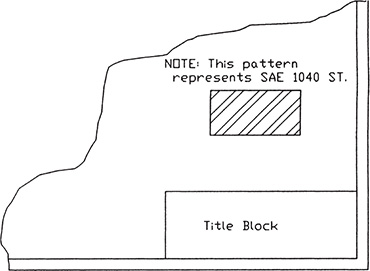
Figure 6-22
6-7 Sectional View Location
Sectional views should be located on a drawing behind the arrows. The arrows represent the viewing direction for the sectional view. See Figure 6-23. If it is impossible to locate sectional views behind the arrows, they may be located above or below, but still behind, the arrowed portion of the cutting plane line. Sectional views should never be located in front of the arrows.
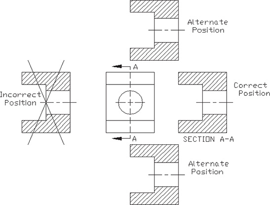
Figure 6-23
Sectional views located on a different drawing sheet from the cutting plane line must be cross referenced to the appropriate cutting plane line. See Figure 6-24. The boxed notation C/3 SHT2 next to the cutting plane line means that the sectional view may be found in zone C/3 on sheet 2 of the drawing.
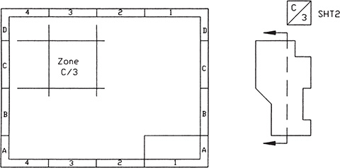
Figure 6-24
The location of the sectional view must be referenced to the cutting plane line if the view’s location is not near the cutting plane. The notation C/3 SHT2 defines the location of the cutting plane line for the sectional view.
The reference numbers and letters are based on a drawing area charting system similar to that used for locating features on maps. A sectional view located at C/3 SHT2 can be found by going to sheet 2 of the drawing and then drawing a vertical line from the box marked 3 at the top or bottom of the drawing and a horizontal line from the box marked C on the left or right edge of the drawing. The sectional view should be located somewhere near the intersection of the two lines.
6-8 Holes in Sections
Figure 6-25 shows a sectional view of an object that contains three holes. As with orthographic views, a conical point must be included on holes that do not completely penetrate the object.
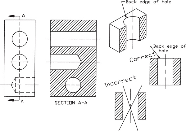
Figure 6-25
A common mistake is to omit the back edge of a hole when drawing a sectional view. Figure 6-25 shows a hole drilled through an object. Note that the sectional view includes a straight line across the top and bottom edges of the view that represents the back edges of the hole.
Figure 6-26 shows a countersunk hole, a counterbored hole, a spotface, and a hole through a boss. Again, any hole that does not completely penetrate the object must include a conical point.

Figure 6-26
6-9 Gradients
In AutoCAD, a gradient is shading that varies in intensity. Figure 6-27 shows a rectangular shape with two internal circles. The figure also shows the same shape with various gradients added.
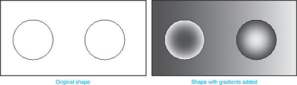
Figure 6-27
To Create a Gradient
- Select the Gradient tool from the Draw panel.
The Hatch Creation panels will appear. See Figure 6-28.

Figure 6-28
- Click a point within the area to which to apply the gradient.
- Right-click the mouse, and select the Enter option.
The gradient’s pattern, color, angle, and density, among other properties, are controlled through the Hatch Creation panels. Figure 6-28 shows some additional patterns available.
6-10 Offset Sections
Cutting plane lines need not be drawn as straight lines across the surface of an object. They may be stepped so that more features can be included in the sectional view. See Figure 6-29. In the object shown in Figure 6-29, the cutting plane line crosses two holes and a directly visible open surface that contains a hole. There is no indication in the sectional view that the cutting plane line has been offset.

Figure 6-29
Cutting plane lines should be placed to include as many features as possible without causing confusion. The intent of using sectional views is to simplify views and to clarify the drawing. Several features can be included on the same cutting plane line so that fewer views are used, giving the drawing a less cluttered look and making it easier for the reader to understand the shape of the object’s features.
Figure 6-30 shows another example of an offset cutting plane line.

Figure 6-30
6-11 Multiple Sections
More than one sectional view may be taken from the same orthographic view. Figure 6-31 shows a drawing that includes three sectional views, all taken from a front view. Each cutting plane line is labeled with a letter. The letters, in turn, are used to identify the appropriate sectional view. Identifying letters are also placed at the ends of the cutting plane lines, behind the arrowheads. Identifying letters are also placed below the sectional view and written in the format SECTION A-A, SECTION B-B, and so on. The abbreviation SECT may also be used: SECT A-A, SECT B-B.
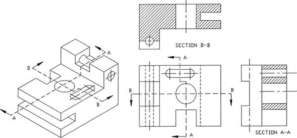
Figure 6-31
The letters I, O, and X are generally not used to identify sectional views, because they can easily be misread. If more than 23 sectional views are used, the lettering starts again with double letters: AA-AA, BB-BB, and so on.
6-12 Aligned Sections
Cutting plane lines taken at angles on circular shapes may be aligned, as shown in Figure 6-32. Aligning the sectional views prevents the foreshortening that would result if the view were projected from the original cutting plane line location. A foreshortened view would not present an accurate picture of the object’s surfaces.
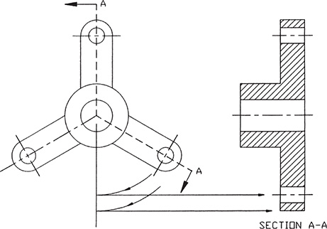
Figure 6-32
6-13 Drawing Conventions in Sections
Slots and small holes that penetrate cylindrical surfaces may be drawn as straight lines, as shown in Figure 6-33. Larger holes—that is, holes whose diameters are greater than the radii of their cylinders—should be drawn showing an elliptical curvature.

Figure 6-33
Intersecting holes are represented by crossed lines, as shown in Figure 6-34. The crossed lines are drawn from the intersecting corners of the holes.

Figure 6-34
6-14 Half, Partial, and Broken-Out Sectional Views
Half and partial sectional views allow a designer to show an object by an orthographic view and a sectional view within one view. A half-sectional view is shown in Figure 6-35. Half of the view is a sectional view; the other half is a normal orthographic view including hidden lines. The cutting plane line is drawn as shown and includes an arrowhead at only one end of the line.

Figure 6-35
Figure 6-36 shows a partial sectional view. It is similar to a half-sectional view, but the sectional view is taken at a location other than directly on a centerline or one defined by a cutting plane line. A broken line is used to separate the sectional view from the orthographic view. A broken line is a freehand line drawn through the Sketch command.

Figure 6-36
Broken-out sectional views are like small partial views. They are used to show only small internal portions of an object. Figure 6-37 shows a broken-out sectional view. Broken lines are used to separate the broken-out section from the rest of the orthographic views.
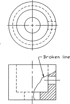
Figure 6-37
To Draw a Broken Line
- Type Sketch in response to a command prompt.
Command:_sketch
Record Increment <0.1000>:
- Press Enter.
Sketch. Pen eXit Quit Record Erase Connect:
- Press the left mouse button.
<Pen down>
- Move the cursor across the screen. A green freehand line will emerge from the crosshairs as it is moved.
- Press the left mouse button again.
<Pen up>
The crosshairs can now be moved without producing a sketched line.
- Select Record from the menu.
23 lines recorded
The number of lines generated and recorded will depend on the length of the line and the size of the line increment.
- Select eXit from the menu.
Command:
Do not use the right mouse button to exit the Sketch command. If the right mouse button is pressed, a line will be drawn from the end of the sketched line to the present location of the crosshairs. Use eXit to end the Sketch command.
6-15 Removed Sectional Views
Removed sectional views are used to show how an object’s shape changes over its length. Removed sectional views are most often used with long objects whose shape changes continuously over its length. See Figure 6-38. The sectional views are not positioned behind the arrowheads, but are positioned across the drawing as shown; however, the view orientation is the same as it would be if the view were projected from the arrowheads; it is simply located in a different position in the drawing.
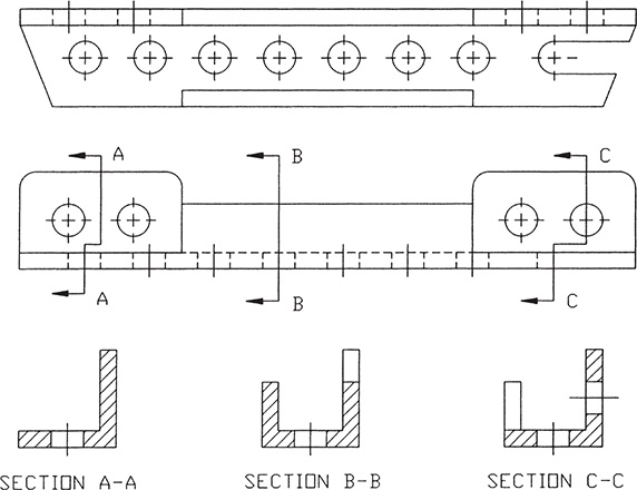
Figure 6-38
It is good practice to identify the cutting plane lines and the sectional views in alphabetical order. This will make it easier for the drawing’s readers to find the sectional views.
6-16 Breaks
It is often convenient to break long continuous shapes so that they take up less drawing space. There are two drawing conventions used to show breaks: freehand lines used for rectangular shapes, and S-breaks used for cylindrical shapes. See Figure 6-39. Freehand break lines are drawn by use of the Sketch command as explained in Section 6-14. Instructions for drawing S-breaks follow.
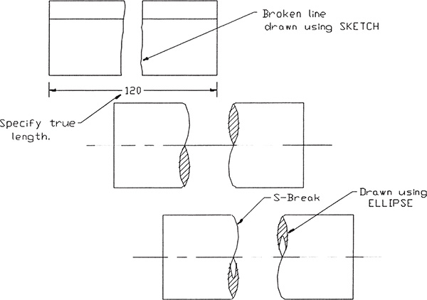
Figure 6-39
To Draw an S-Break (See Figure 6-40.)
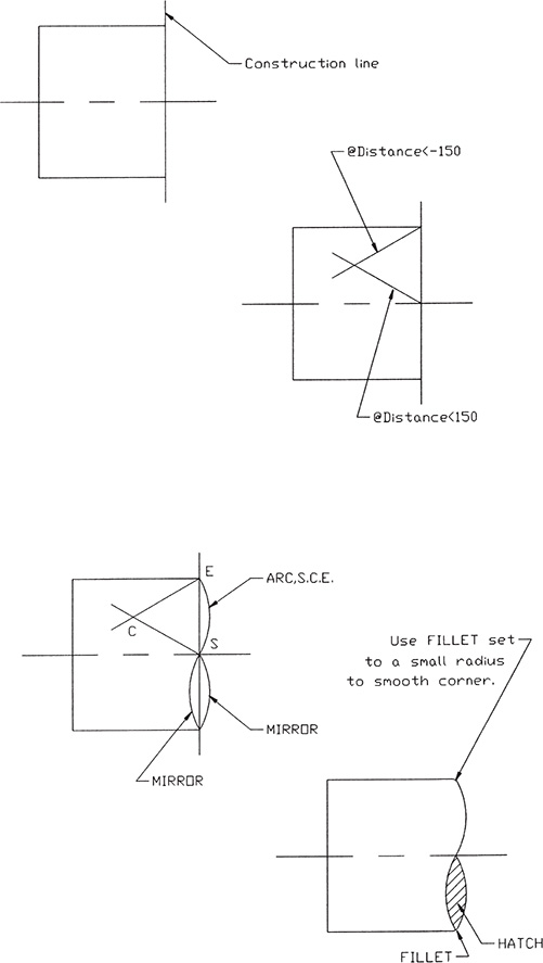
Figure 6-40
- Draw a rectangular view of the cylindrical object, and draw a construction line where the break is to be located. The rectangular view should include a centerline.
- Draw two 30° lines: one from the intersection of the construction line and the outside edge line of the view, and the other from the intersection of the construction line and the centerline as shown.
- Draw an arc, using the intersection created in step 2 as the center point. Mirror the arc about the centerline and then about the construction line.
- Use Fillet, set to a small radius, to smooth the corners between the arc and the edge lines. Any small radius may be used for the fillet, provided that it produces a smooth visual transition between the arc and the edge lines.
- Erase and trim any excess lines.
- Hatch the area created by the two arcs and fillet as shown.
The Copy, Mirror, and Move commands may be used to create the opposing S-break as shown in Figure 6-39. The internal shapes of the tubular S-breaks are created by using Ellipse. Position the end of the ellipse according to the thickness specifications, and determine the elliptical shape by eye. Trim the sectional lines from the inside of the ellipse.
6-17 Sectional Views of Castings
Cast objects are usually designed to include a feature called a rib. See Figure 6-41. Ribs add strength and rigidity to an object. Sectional views of ribs do not include complete section lines, because this is considered misleading to the reader. Ribs are usually narrow, and a large sectioned area gives the impression of a denser and stronger area than is actually on the casting.
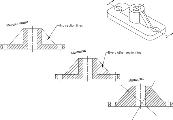
Figure 6-41
There are two conventions used to present sectional views of cast ribs: one that does not draw any section lines on the ribs, and one that puts every other section line on the rib. Sectional views of castings that do not include section lines on ribs are created by using Hatch for those areas that are to be hatched.
6-18 Exercise Problems
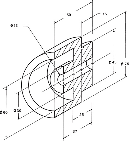
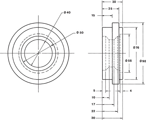
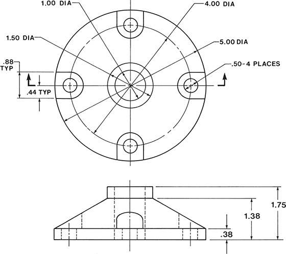
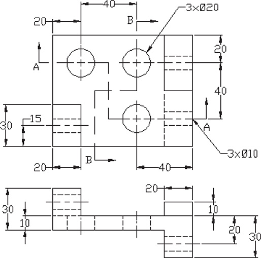
Draw a complete front view and a sectional view of the objects in Exercise Problems EX6-1 through EX6-4. The cutting plane line is located on the vertical centerline of the object.
EX6-1 Millimeters

EX6-2 Millimeters
EX6-3 Inches

EX6-4 Millimeters
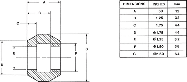
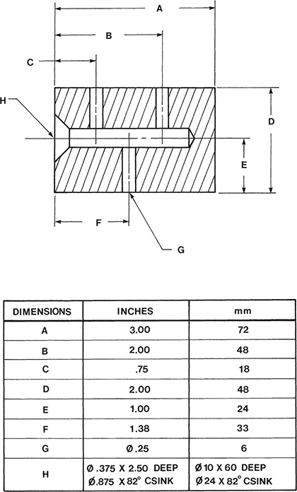
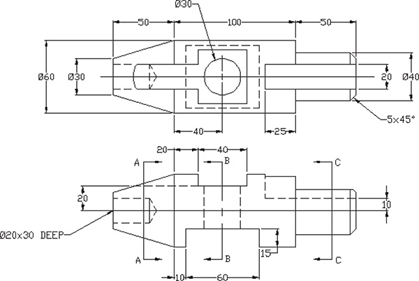
Draw the following sectional views, using the given dimensions:
EX6-5
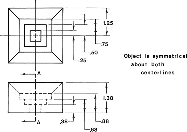
Resketch the given top view and Section A-A; then sketch Sections B-B, C-C, and D-D.
EX6-6
EX6-7

Resketch the given front views in Exercise Problems EX6-8 through EX6-11, and replace the given side orthographic view with the appropriate sectional view.
EX6-8

EX6-9

EX6-10 Inches
EX6-11
Redraw the given front views in Exercise Problems EX6-12 through EX6-15, and replace the given side orthographic view with the appropriate sectional view. The cutting plane is located on the vertical centerlines of the objects.
EX6-12 Inches

EX6-13 Inches
EX6-14 Inches
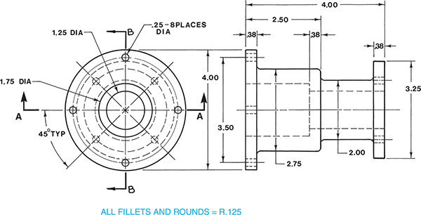
EX6-15 Millimeters
Draw the top orthographic view and the indicated sectional view.
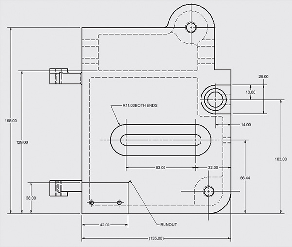
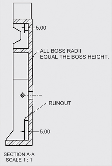
EX6-16 Millimeters
EX6-17 Inches

EX6-18 Millimeters

EX6-19 Millimeters
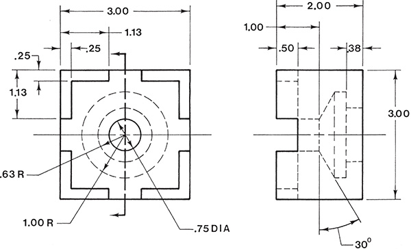
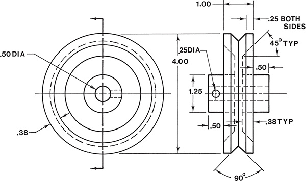
Redraw the given views, and add the specified sectional views in Exercise Problems EX6-20 through EX6-34.
EX6-20 Inches
EX6-21 Inches

EX6-22 Inches

EX6-23 Inches
EX6-24 Inches
Redraw the given front and top views, and add Sections A-A, B-B, and C-C as indicated.

EX6-25 Millimeters
EX6-26 Inches
EX6-27 Inches
EX6-28 Inches

EX6-29 Millimeters

EX6-30 Millimeters

EX6-31 Millimeters

EX6-32 Millimeters
EX6-33 Millimeters

EX6-34 Inches

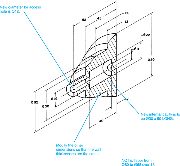
EX6-35
New customer requirements dictate that a part be redesigned according to the given specifications. Draw a front and a sectional view of the redesigned part.
- The diameters of the Ø9 internal access holes are to be increased to Ø12.
- The diameter of the internal cavity is to be increased to Ø30.
- The length of the internal cavity is to be increased from 33 to 50.
- All other sizes and distances are to be increased to maintain the same wall thickness.
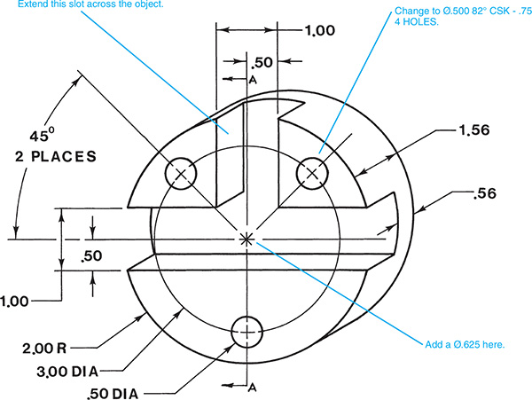
EX6-36
An object is to be redesigned as follows:
- Extend the 1.00-inch vertical slot all the way through the object, creating four corner sections.
- Locate countersunk holes in each of the four corner sections. Note that two of the corner sections presently have Ø.50 holes. The countersink specifications are Ø.50 − 82°, Ø.75.
- Locate a Ø.625 hole in the center of the object.

EX6-37
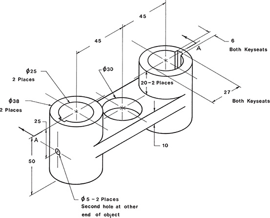
Given the following front, top, and sectional views, create a 3D model of the object:

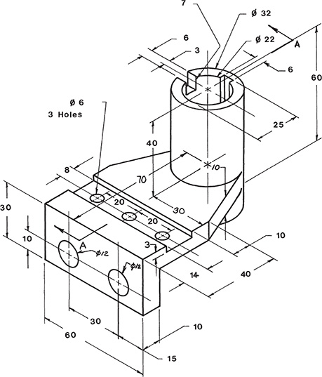
EX6-38
Given the following views, create a 3D model of the object.