
Chapter 3
Overview of 5G Use Cases and Architecture
Learning Objectives
After studying this chapter, you should be able to:
Present an overview of the types of use cases enabled by 5G
Discuss the user experience and performance requirements of use cases in various categories
Present an overview of the NGMN 5G architecture
Present an overview of the 3GPP 5G core network architecture
Present an overview of the 3GPP 5G radio access network architecture
This chapter presents a high-level view of the concepts underlying 5G. Section 3.1 provides an overview of the types of use cases enabled by 5G. This section presents three taxonomies or groupings of use cases developed by three different organizations. These different perspectives enable you to develop a solid grasp of the types of use cases that are emerging with 5G and their chief characteristics.
Section 3.2 presents a 5G architecture framework developed by the Next Generation Mobile Networks (NGMN) Alliance. This framework is widely accepted within the telecommunications industry. The framework provides an excellent high-level rendering of the overall 5G system and enables you to understand the overall structure of 5G.
Section 3.3 presents architecture models for the 5G core network and radio access network developed by the 3rd Generation Partnership Project (3GPP), which is the organization developing the technical specifications for 5G. The diagrams presented in this section illustrate the framework being used for the development of detailed technical specifications and enable you to see the context of the separate technical aspects of 5G that are described in subsequent chapters and to see how the various technical elements of 5G fit together.
3.1 5G Use Cases
There is a reciprocal cause–effect relationship between use cases and the capabilities being designed into 5G networks. As users and organizations have come to depend increasingly on wireless and Internet-based applications, these users have come to expect more capability, in terms of data rate and range of features, from wireless networks. These expectations create a demand that justifies the enormous investment required to deploy 5G networks. Conversely, 5G networks are the logical next step in the evolution of cellular networks, and the new capabilities provided by 5G enable users to envision a wide range of new applications, termed use cases, in the standards and specifications documents.
This section looks at examples of use cases, or applications, for 5G compiled by three different organizations: ITU Radiocommunication Sector (ITU-R), 5G Americas, and the Next Generation Mobile Networks (NGNM) Alliance. The three compilations provide a good sense of the possibilities enabled by 5G.
ITU-R
ITU-R Report M.2441 describes 16 emerging use cases for IMT-2020, as shown in Figure 3.1. M.2441 provides a description of a number of specific applications encompassed by each use case, as well as a summary of technical capabilities of the IMT systems needed to support each use case.

FIGURE 3.1 Emerging 5G Use Cases (ITU-R)
Chapter 2, “5G Standards and Specifications,” briefly describes each of the 16 use cases.
5G Americas
5G Americas is an industry trade organization composed of leading telecommunications service providers and manufacturers. The organization’s mission is to advocate for and foster the advancement and full capabilities of LTE (Long Term Evolution) wireless technologies and their evolution to 5G throughout the ecosystem’s networks, services, applications, and connected devices in the Western Hemisphere. 5G Americas is affiliated with 3GPP as a market representation partner.
The 5G Americas document 5G Services & Use Cases (November 2017) describes 16 use cases and provides a framework for mapping use cases to 5G capabilities. Figure 3.2, from the 5G Americas document, shows the framework, which has two dimensions. One dimension consists of the three usage scenarios similar to those defined by ITU-R and described in Chapter 2.

FIGURE 3.2 Some 5G Use Cases Grouped by Type of Interaction and the Range of Performance Requirements (5G Americas)
The three scenarios, based on their performance requirements, are:
Enhanced mobile broadband (eMBB): These use cases generally have requirements for higher data rates and better coverage.
Massive scale communication: These use cases generally have requirements to support a very large number of devices in a small area and, therefore, very high device density.
Ultra-reliable low-latency service: These use cases have very strict requirements on latency and reliability and are also referred to as ultra-reliable and low-latency communications (URLLC).
The other dimension characterizes use cases based on whether they involve human-to-human, human-to-machine, or machine-to-machine communication. As indicated in Figure 3.2, a use case may correspond to more than one type of interaction or more than one usage scenario. This depiction clarifies the requirements for the various use cases.
NGMA Alliance
The Next Generation Mobile Networks (NGNM) Alliance is an association of mobile operators, vendors, manufacturers, and research institutes. It is an open forum whose goal is to ensure that the standards for next-generation network infrastructure, service platforms, and devices meet the requirements of operators and, ultimately, that they will satisfy end user demand and expectations. The NGMN Alliance complements and supports standards organizations by providing a coherent view of what mobile operators require. NGMN is affiliated with 3GPP as a market representation partner.
NGMN’s 5G White Paper (February 2015) defines 24 use cases intended as representative examples of the applications for 5G and meant to highlight the diversity of performance requirements that 5G networks must satisfy. Figure 3.3, from the white paper, illustrates the framework for positioning use cases in a way that clarifies requirements. At a high level, use cases are grouped into eight use case families. These families are roughly similar to the three usage scenarios defined by ITU-R but at a greater granularity. Each family reflects the dominant characteristic of the use cases in that family.

FIGURE 3.3 Use Case Categories Definition (NGNM)
Each family is in turn divided into a number of categories. The categories represent distinct types of demands on the 5G network in terms of user experience requirements and system performance requirements. For each use case category, one set of requirement values is given, which is representative of the extreme use cases(s) in the category. As a result, satisfying the requirements of a category leads to satisfying the requirements of all the use cases in this category. Tables 3.1 and 3.2, from the white paper, summarize the requirements.
TABLE 3.1 User Experience Requirements
Use Case Category |
User-Experienced Data Rate |
E2E Latency |
Mobility |
Broadband access in dense areas |
DL: 300 Mbps UL: 50 Mbps |
10 ms |
On demand: 0–100 km/h |
Indoor ultra-high broadband access |
DL: 1 Gbps UL: 500 Mbps |
10 ms |
Pedestrian |
Broadband access in a crowd |
DL: 25 Mbps UL: 50 Mbps |
10 ms |
Pedestrian |
50+ Mbps everywhere |
DL: 50 Mbps UL: 25 Mbps |
10 ms |
0–120 km/h |
Ultra-low-cost broadband access for low average revenue per user (ARPU) areas |
DL: 10 Mbps UL: 10 Mbps |
50 ms |
On demand: 0–50 km/h |
Mobile broadband in vehicles (cars, trains) |
DL: 50 Mbps UL: 25 Mbps |
10 ms |
On demand: Up to 500 km/h |
Airplanes connectivity |
DL: 15 Mbps per user UL: 7.5 Mbps per user |
10 ms |
Up to 1000 km/h |
Massive low-cost/long-range/low-power machine-type communication (MTC) |
Low (typically 1–100 kbps) |
Seconds to hours |
On demand: 0–500 km/h |
Broadband MTC |
See the requirements for the broadband access in dense areas and 50+ Mbps everywhere categories |
||
Ultra-low latency |
DL: 50 Mbps UL: 25 Mbps |
< 1 ms |
Pedestrian |
Resilience and traffic surge |
DL: 0.1–1 Mbps UL: 0.1–1 Mbps |
Regular communication: not critical |
0–120 km/h |
Ultra-high reliability and ultra-low latency |
DL: 50 kbps–10 Mbps UL: a few bps–10 Mbps |
1 ms |
On demand: 0–500 km/h |
Ultra-high availability and reliability |
DL: 10 Mbps UL: 10 Mbps |
10 ms |
On demand: 0–500 km/h |
Broadcast-like services |
DL: Up to 200 Mbps UL: Modest (e.g., 500 kbps) |
< 100 ms |
On demand: 0–500 km/h |
TABLE 3.2 System Performance Requirements
Use Case Category |
Connection Density |
Traffic Density |
|
Broadband access in dense areas |
200–2500/km2 |
DL: 750 Gbps/km2 UL: 125 Gbps/km2 |
|
Indoor ultra-high broadband access |
75,000/km2 (75/1000 m2 office) |
DL: 15 Tbps/km2 (15 Gbps/1000 m2) UL: 2 Tbps/km2 (2 Gbps/1000 m2) |
|
Broadband access in a crowd |
150,000/km2 (30,000/stadium) |
DL: 3.75 Tbps/km2 (0.75 Tbps/stadium) UL: 7.5 Tbps/km2 (1.5 Tbps/stadium) |
|
50+ Mbps everywhere |
400/km2 suburban 100/km2 rural |
DL: 20 Gbps/km2 suburban UL: 10 Gbps/km2 suburban DL: 5 Gbps/km2 rural UL: 2.5 Gbps/km2 rural |
|
Ultra-low-cost broadband access for low ARPU areas |
16/km2 |
16 Mbps/km2 |
|
Mobile broadband in vehicles (cars, trains) |
2000/km2 (500 active users per train × 4 trains or 1 active user per car × 2000 cars) |
DL: 100 Gbps/km2 (25 Gbps per train, 50 Mbps per car) UL: 50 Gbps/km2 (12.5 Gbps per train, 25 Mbps per car) |
|
Airplanes connectivity |
80 per plane 60 airplanes per 18,000 km2 |
DL: 1.2 Gbps/plane UL: 600 Mbps/plane |
|
Massive low-cost/long-range/low-power MTC |
Up to 200,000/km2 |
Not critical |
|
Broadband MTC |
See the requirements for the broadband access in dense areas and 50+ Mbps everywhere categories |
||
Ultra-low latency |
Not critical |
Potentially high |
|
Resilience and traffic surge |
10,000/km2 |
Potentially high |
|
Ultra-high reliability and ultra-low latency |
Not critical |
Potentially high |
|
Ultra-high availability and reliability |
Not critical |
Potentially high |
|
Broadcast-like services |
Not relevant |
Not relevant |
|
3.2 NGMN 5G Architecture Framework
NGMN introduced a framework for the 5G architecture in its 2015 white paper and subsequently elaborated the framework in a later document, 5G End-to-End Architecture Framework (August 2019). The NGMN framework emphasizes the need for modular network functions that could be deployed and scaled on demand to accommodate various use cases in an agile and cost-efficient manner. The NGMN approach is built on the concept of the softwarization of 5G networks. In essence, softwarization is an overall approach for designing, implementing, deploying, managing, and maintaining network equipment and/or network components through software programming.
Four approaches to softwarization are important in 5G networks and reflected in the NGMN model:
Software-defined networking (SDN): An approach to designing, building, and operating large-scale networks based on programming the forwarding decisions in routers and switches via software from a central server. SDN differs from traditional networking, which requires configuration of each device separately and relies on protocols that cannot be altered. Chapter 7, “Software-Defined Networking,” covers SDN.
Network functions virtualization (NFV): The virtualization of compute, storage, and network functions by implementing these functions in software and running them on virtual machines. Chapter 8, “Network Functions Virtualization,” covers NFV.
Edge computing: A distributed information technology (IT) architecture in which client data is processed at the periphery of the network, as close to the originating source as possible.
Cloud-edge computing: A form of edge computing that offers application developers and service providers cloud computing capabilities as well as an IT service environment at the edge of a network. The aim is to deliver compute, storage, and bandwidth much closer to data inputs and/or end users. Chapter 10, “Multi-Access Edge Computing,” covers cloud-edge computing.
Layered Functionality
Figure 3.4 illustrates the NGMN architecture framework. The architecture comprises three layers and an end-to-end (E2E) management and orchestration entity.
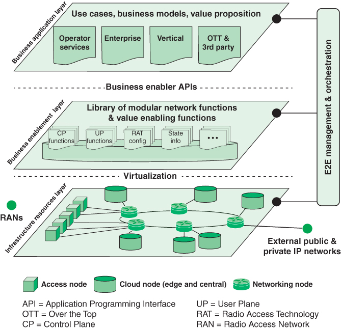
FIGURE 3.4 5G Architecture (NGMN)
The infrastructure resource layer consists of the physical resources and system software of a fixed-mobile converged (FMC) network. Figure 3.4 shows in detail the core network portion, which includes these types of devices:
Cloud nodes: These nodes provide cloud services, software, and storage resources. There are likely to be one or more central cloud nodes that provide traditional cloud computing service. In addition, cloud-edge nodes provide low latency and higher-security access to client devices at the edge of the network. All of these nodes include virtualization system software to support virtual machines and containers. NFV enables effective deployment of cloud resources to the appropriate edge node for a given application and given fixed or mobile user. The combination of SDN and NFV enables the movement of edge resources and services to dynamically accommodate mobile users.
Networking nodes: These are IP routers and other types of switches for implementing a physical path through the network for a 5G connection. SDN provides for flexible and dynamic creation and management of these paths.
Access nodes: These provide an interface to radio access networks (RANs), which in turn provide access to mobile user equipment (UE). SDN creates paths that use an access node for one or both ends of a connection involving a wireless device.
Hardware and software resources at the infrastructure resources layer are exposed to higher layers and to the end-to-end management and orchestration entity through relevant application programming interfaces (APIs). Performance and status monitoring as well as configurations are intrinsic parts of such an API.
The business enablement layer is a library of all functions required within a converged network in the form of modular architecture building blocks, including functions realized by software modules that can be retrieved from the repository to the desired location, and a set of configuration parameters for certain parts of the network (e.g., radio access). The functions and capabilities are called upon request by the orchestration entity, through relevant APIs. For certain functions, multiple variants might exist. For example, there may be different implementations of the same functionality that have different performance or characteristics. The different levels of performance and capabilities offered could be utilized to differentiate the network functionality much more than in today’s networks (e.g., to offer mobility functions such as nomadic mobility, vehicular mobility, or aviation mobility, depending on specific needs). Specific types of components at this layer include:
Control plane functions: These are modules that implement the control signaling functions within the network, as well as control signals associated with SDN and NFV.
User plane functions: These modules deal with the exchange of user data over a connection.
Radio access technology (RAT) configuration: These functions facilitate the configuration of elements in the RAN, including base stations.
State information: State information is split from functions and nodes and managed separately. This includes the state of network connections and RAN radio channels.
With the use of SDN and NFV, 5G networks can support flexible functions and capabilities. The functions at the business enablement layer can tailor connections, configurations, and resource deployment for each use case.
The business application layer contains specific applications and services that support the following users of the 5G network:
Mobile network operator: A mobile network operator is a wireless telecommunications organization that provides wireless voice and data communication for its subscribed mobile users. The operator owns or controls the complete telecom infrastructure for hosting and managing mobile communications between the subscribed mobile users with users in the same and external wireless and wired telecom networks, including radio spectrum allocation, wireless network infrastructure, backhaul infrastructure, billing, customer care, provisioning computer systems, and marketing and repair organizations. Mobile network operators are also known as wireless service providers, wireless carriers, and cellular companies.
Enterprise: An enterprise is a business that offers services over the mobile network. These services include applications that run on mobile devices and cloud-based services that enable application portability across multiple devices.
Verticals: An industry vertical is an organization that provides products and/or services targeted to a specific industry, trade, profession, or other group of customers with specialized needs. A vertical might provide a range of products or services useful in the banking industry or healthcare. In contrast, a horizontal provides products or services that address a specific need across multiply industries, such as accounting or billing products and services. Some 5G use cases are realized by standalone private networks managed by the vertical industry itself rather than the network service provider (NSP). A good example is factory automation. In such cases, the vertical can own and control its own application packages and business application layer.
Over-the-top (OTT) and third parties: OTT or third-party services can be defined as any services provided over the Internet and mobile networks that bypass traditional operators’ distribution channel. Cooperation between the mobile network operator and the OTT involves providing quality of service (QoS) and latency attributes in network slices. Examples of OTTs include:
Voice over Internet Protocol (VoIP): Skype, Viber, etc.
Short Message Service (SMS): WhatsApp, Kakao Talk, Line, Telegram, etc.
Apps: Search portals, news portals, banking, weather, shopping, etc.
Cloud services: Dropbox, Google Drive, Apple iCloud, etc.
Internet television (video streaming): Netflix, Hulu, YouTube, Amazon Video, etc.
At the interface to the end-to-end management and orchestration entity, users at the business application layer can build dedicated network slices for an application or map an application to existing network slices.
The E2E management and orchestration entity is the contact point to translate the use cases and business models into actual network functions and slices. It defines the network slices for a given application scenario, chains the relevant modular network functions, assigns the relevant performance configurations, and finally maps all of this onto the infrastructure resources. It also manages scaling of the capacity of those functions as well as their geographic distribution. In certain business models, it could also possess capabilities to allow for third parties to create and manage their own network slices.
Network Slicing
Chapter 2 introduces the concept of network slicing. Figure 2.11 suggests that slices can divide classes of internal network functions, such as dividing eMBB from mMTC from URLLC. The NGMN framework suggests that slices could effectively partition networks in such a way that different classes of user equipment, utilizing their respective sets of radio access technologies, would perceive quite different infrastructure configurations, even though they would be accessing resources from the same pools.
NGMN defines a network slice as being composed of a collection of 5G network functions and specific RAT settings combined together for the specific use case or business model. Thus, a 5G slice can span all domains of the network—software modules running on cloud nodes, specific configurations of the transport network supporting flexible location of functions, and a dedicated radio configuration or even a specific RAT—as well as configuration of the 5G device.
Figure 3.5 illustrates three use cases highlighted in the NGMN white paper. The blacked-out core network resources represent resources not used to create the network slice.
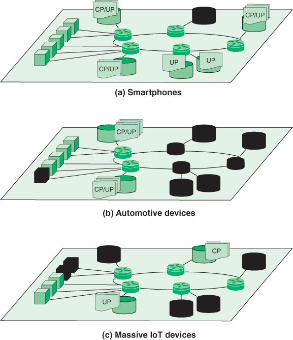
FIGURE 3.5 5G Network Slices Implemented on the Same Infrastructure
Cloud nodes that are part of the slice may include the following:
Control plane (CP) functions associated with one or more user plane (UP) functions (e.g., a reusable or common framework of control)
Service- or service category–specific control plane and user plane function pairs (e.g., user-specific multimedia application session)
The first network slice depicted in Figure 3.5 is for a typical smartphone use case. Such a slice might have fully fledged functions distributed across the network. The second network slice in Figure 3.5 indicates the type of support that may be allocated for automobiles in motion. This use case emphasizes the need for security, reliability, and low latency. A configuration to achieve this would limit core network resources to nearby cloud edge nodes, plus the recruitment of sufficient access nodes to support the use case. The final use case illustrated in Figure 3.5 is for a massive IoT deployment, such as a huge number of sensors. The slice can contain just some basic CP and UP functions with, for example, no mobility functions. This slice would only need to engage the access nodes nearest the IoT device deployment.
Thus, as Figures 3.4 and 3.5 suggest, a layered architecture with emphasis on softwarization provides the flexibility needed to fully exploit the 5G infrastructure.
3.3 3GPP 5G Architecture
As discussed in Chapter 2, the 3rd Generation Partnership Project (3GPP) is the organization responsible for developing reports and specifications that define 5G networks. The project covers cellular telecommunications technologies—including the air interface, RAN, core network, and service capabilities—that provide a complete system description for 5G mobile telecommunications. The 3GPP specifications also provide hooks for fixed access to the core network and for interworking with 4G networks and networks outside the 3GPP specifications.
Hundreds of 3GPP reports and specifications related to 5G together describe an extraordinarily complex system. This book provides an overview that encompasses the scope of 5G technology and networks, based on the 3GPP documents. This section provides a “big picture” overview of 5G, summarizing the two key 3GPP documents that together describe the 5G architecture:
TS 23.501 (Technical Specification Group Services and System Aspects; System Architecture for the 5G System (5GS); Stage 2 (Release 16), December 2020): This document describes the core network architecture, together with its services and interfaces.
TS 38.300 (Technical Specification Group Radio Access Network; NR; NR and NG-RAN Overall Description; Stage 2 (Release 16), December 2020): This document describes the radio access network architecture, together with its services and interfaces.
5G Core Network Architecture
The 5G architecture model provides a framework within which detailed specifications can be developed.
Principles
TS 23.501 lists the following as the key principles for the architecture:
Separate the user plane (UP) functions from the control plane (CP) functions to allow independent scalability, evolution, and flexible deployments (e.g., centralized location or distributed [remote] location).
Modularize the function design (e.g., to enable flexible and efficient network slicing).
Wherever applicable, define procedures (i.e., the set of interactions between network functions) as services so that their reuse is possible.
Enable each network function (NF) and its network function services (NFS) to interact with other NF and its NFS directly or indirectly via a service communication proxy, if required. The architecture does not preclude the use of another intermediate function to help route control plane messages.
Minimize dependencies between the access network (AN) and the core network (CN). The architecture is defined with a converged core network with a common AN–CN interface that integrates different access types (e.g., 3GPP access and non-3GPP access).
Support a unified authentication framework.
Support stateless NFs. A stateless NF separates an NF into a processing module and a data store module containing state information. This design results in a more agile NF in terms of scalability, resilience, and ease of deployment [KABL17].
Support capability exposure. As mentioned in Chapter 2, this refers to the ability to provide relevant information about network capabilities to third parties.
Support concurrent access to local and centralized services. To support low-latency services and access to local data networks, UP functions can be deployed close to the access network.
Support roaming with both home-routed traffic as well as local breakout traffic in the visited public land mobile network (PLMN).
Roaming
The final item in the preceding list references some important concepts. A PLMN, often called a carrier, is a telecommunications network that provides mobile cellular services. A home PLMN for a given mobile phone subscriber is the PLMN that is contracted to provide cellular service to the subscriber. Roaming is the ability for a user to function in a serving network different from the home network, called the visited network. Roaming can occur internationally, in which case mobile subscribers get coverage and at least basic services similar to their domestic package from a network operator in another country. For 5G, any user device should work in any other country. With 4G and earlier, there are multiple technologies in use, and a cell phone from one country may not be able to operate on a network in another country. National roaming refers to the ability to move from one mobile operator to another in the same country.
Both the home and visited PLMN use the same network architecture, which defines protocols, services, and interfaces between the home PLMN and the visited PLMN. The 3GPP specifications support two models of operation: home routed and local breakout (LBO). In the home-routed roaming model, the subscriber’s data traffic is serviced by the subscriber’s home network, which gives the home network operator more control over the user’s traffic and is preferable when the relationship between the two operators is not totally trustworthy. In the LBO model, the subscriber’s data is serviced by the visited network; this model delivers more efficient routing in terms of bandwidth and latency. In the case of LBO, the home network owner loses control of the customer and has no role in delivering services to that user. The LBO model is used when there is a trusted relationship between the two operators.
An architecture that includes roaming adds complexity but no change to the basic network services and functionality. Therefore, this section focuses on the non-roaming case.
Architecture Diagrams
TS 23.501 contains a number of architecture diagrams from several different points of view and at varying levels of detail. All of the diagrams depict the architecture in terms of a number of interconnected network functions (NFs). An NF is a processing function in a network that has defined functional behavior and interfaces. A network function can be implemented either as a network element on dedicated hardware, as a software instance running on dedicated hardware, or as a virtualized function instantiated on an appropriate platform.
The interconnection between NFs is represented in two ways:
Service-based representation: NFs within the control plane enable other authorized NFs to access their services. This representation illustrates how a set of services is provided/exposed by a given network interface. This interface defines how one network function within the control plane allows other network functions that have been authorized to access its services. This representation also includes point-to-point reference points where necessary.
Reference point representation: This representation uses labeled point-to-point links to show the interaction that exists between two NFs or between an NF and an external functional module or network. The reference point representation is beneficial when showing message sequence charts. It shows the relationships between NFs that are used in the message sequence charts.
There are several advantages to this form of architectural representation. The modular structure provides a framework for developing detailed specifications for each NF. The service-based interfaces and reference points provide a framework for developing detailed specifications of the interaction between NFs in terms of data formats, protocols, and service calls. In addition, the detailed interface specifications promote interoperability between different hardware/software providers. Finally, this type of architecture definition provides a way of ensuring that all 5G functional and service requirements are satisfied.
Service-Based System Architecture
Figure 3.6, based on TS 23.501, depicts the overall non-roaming 5G service-based architecture (SBA) for the core network. The functional components of the control plane of the network are network functions (NFs) that offer their services to any other applicable NFs via a common framework of interfaces accessible to all NFs. Network repository functions (NRFs) allow every NF to discover the services offered by other NFs present in the network; network exposure functions (NEFs) expose capability information and services of the 5G core network NFs to external entities. This model aims to maximize the modularity, reusability, and self-containment of network functions and to foster the ability to grow flexibly while taking advantage of network functions virtualization and software-defined networking.
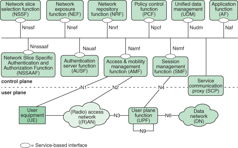
FIGURE 3.6 Non-Roaming 5G System Architecture
The figure includes the following NFs and other modules:
Authentication server function (AUSF): Performs authentication between UE and the network.
Access and mobility management function (AMF): Receives all connection- and session-related information from the user equipment (UE) (N1/N2) but is responsible only for handling connection, registration, reachability, and mobility management tasks. All messages related to session management are forwarded to the session management function (SMF).
Network exposure function (NEF): Provides an interface for outside applications to communicate with the 5G network to obtain network-related information in the following categories:
Monitoring capability: Allows an external entity to request or subscribe to UE-related events of interest. The monitored events include a UE’s roaming status, UE loss of connectivity, UE reachability, and location-related events.
Provisioning capability: Allows an external entity to provide information about expected UE behavior to the 5G system (e.g., predicted UE movement, communication characteristics).
Policy/charging capability: Handles QoS and charging policy for the UE, based on a request from an external party.
Analytics reporting capability: Allows an external party to fetch or subscribe/unsubscribe to analytics information generated by the 5G system.
Network repository function (NRF): Allows NFs to register their functionality and to discover the services offered by other NFs present in the network.
Network slice selection function (NSSF): Selects the set of network slice instances to accommodate the service request from a UE. When a UE requests registration with the network, AMF sends a network slice selection request to NSSF with information on the preferred network slice selection. The NSSF responds with a message that includes a list of appropriate network slice instances for the UE.
Network slice-specific authentication and authorization (NSSF): Performs authentication and authorization specific to a slice.
Policy control function (PCF): Provides functionalities for the control and management of policy rules, including rules for QoS enforcement, charging, and traffic routing. PCF enables end-to-end QoS enforcement with QoS parameters (e.g., maximum bit rate, guaranteed bit rate, priority level) at the appropriate granularity (e.g., per UE, per flow, per protocol data unit [PDU] session).
Session management function (SMF): Responsible for PDU session establishment, modification, and release between a UE and a data network. A PDU session, or simply a session, is an association between the UE and a data network that provides a PDU connectivity service. A PDU connectivity service is a service that provides for the exchange of PDUs between a UE and a data network.
Unified data management (UDM): Responsible for access authorization and subscription management. UDM works with the AMF and AUSF as follows: The AMF provides UE authentication, authorization, and mobility management services. The AUSF stores data for authentication of UEs, and the UDM stores UE subscription data.
User plane function (UPF): Handles the user plane path of PDU sessions. This function is described subsequently.
Application function (AF): Provides session-related information to the PCF so that the SMF can ultimately use this information for session management. The AF interacts with application services that require dynamic policy control. The AF extracts session-related information (e.g., QoS requirements) from application signaling and provides it to the PCF in support of its rule generation. An example is the IP multimedia subsystem (IMS), which may interface with the PCRF to request QoS support for VoIP calls.
User equipment (UE): Allows a user access to network services. An example is a mobile phone. For the purpose of 3GPP specifications, the interface between the UE and the network is the radio interface.
(Radio) Access Network ((R)AN): Provides access to a 5G core network. This includes the 5G RAN and other wireless and wired access networks.
Data network (DN): Allows UE to be logically connected by a session. It may be the Internet, a corporate intranet, or an internal services function within the mobile network operator’s core (including content distribution networks).
Service communication proxy (SCP): Allows NFs and NFSs to communicate directly or indirectly. The SCP enables multiple NFs to communicate with each other and with user plane entities in a highly distributed multi-access edge compute cloud environment. This provides routing control, resiliency, and observability to the core network.
The ovals on NFs in Figure 3.6 indicate service interfaces that can be accessed by other NFs. Each interface is identified by a label consisting of an uppercase N followed by the abbreviation of the NF in lowercase. For example, the network slice selection function has a service interface labeled Nnssf.
It is informative to compare Figure 3.6 with Figure 2.13, which shows the ITU-T Y.3102 (Framework of the IMT-2020 Network, May 2018) representation of the core network, which provides a somewhat different functional breakdown. This can be considered an earlier version of the core network architecture that has been superseded by the current 3GPP architecture.
Reference Point Representation
Figure 3.7, based on TS 23.501, depicts the overall non-roaming 5G architecture using the reference point representation, showing how the NFs interact with each other.
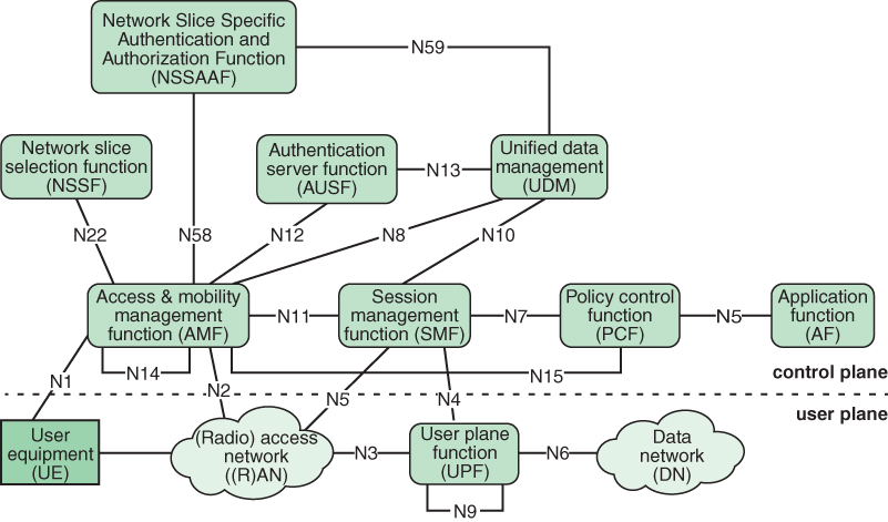
FIGURE 3.7 Non-Roaming 5G System Architecture in Reference Point Representation
Note that there are fewer interconnections depicted in Figure 3.7 than in Figure 3.6. Within the control plane, the interconnections in Figure 3.6 indicate which NFs can access the services of which other NFs. The interconnections of Figure 3.7 indicate which NFs communicate with each other directly, without going through an intermediate NF. The term directly does not mean that there is a physical point-to-point link between NFs connected on the diagram. Rather, it means that there is a protocol for the exchange of messages between the connected entities that is not relayed through another NF. Each such link is labeled with a reference point expressed as an uppercase N followed by a number. For example, the logical connection between the session management function and the policy control function is labeled reference point N7.
In Figure 3.7, two reference points loop back to the same function: N9 and N14. The N9 reference point is an interface between two distinct UPFs used for forwarding packets. The N14 reference point is between two AMFs, one acting as a source AMF for a data transfer and the other acting as a destination AMF.
User Plane Function
User plane functions handle the user plane path of PDU sessions. 3GPP specifications support deployments with a single UPF or multiple UPFs for a given PDU session. UPF selection is performed by SMF. UPF functions include:
Packet routing and forwarding.
Anchor point for intra-/inter-RAT mobility (when applicable). Anchor points are transit nodes in the network used for forwarding PDUs along a session from a UE to the destination.
External PDU session point of interconnect to data network.
Packet inspection (e.g., application detection based on a service data flow [SDF] template). An SDF provides end-to-end packet flow between an end user and an application; this is discussed in Chapter 9, “Core Network Functionality, QoS, and Network Slicing.”
User plane part of policy rule enforcement (e.g., gating, redirection, traffic steering).
Traffic usage reporting.
QoS handling for the user plane, such as uplink/downlink rate enforcement.
Uplink traffic verification (SDFs to QoS flow mapping). A QoS flow is the lowest level of granularity for defining end-to-end QoS policies. A QoS flow may contain multiple SDFs; this is discussed in Chapter 9.
Transport-level packet marking in the uplink and downlink.
Downlink packet buffering and downlink data notification triggering.
Sending and forwarding of one or more end markers to the source NG-RAN node.
Radio Access Network Architecture
Figure 3.8, from TS 38.300, depicts the overall RAN architecture.
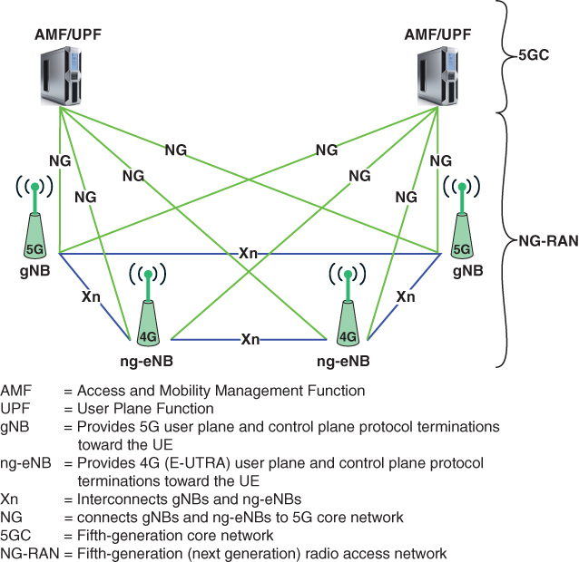
FIGURE 3.8 Overall Radio Access Network Architecture
There are two types of base stations, called NG-RAN nodes:
gNB: Provides 5G user plane and control plane protocol terminations toward the UE.
ng-eNB: Provides 4G (E-UTRA) user plane and control plane protocol terminations toward the UE and connects via the NG interface to the 5G core. This enables 5G networks to support UE that use the 4G air interface. However, the UE must still implement the 5G protocols to interact with the 5G core network.
The gNBs and ng-eNBs are interconnected with each other by means of the Xn interface. The gNBs and ng-eNBs are also connected by means of the NG interfaces to the core network (5GC)—specifically, to the AMF (access and mobility management function) by means of the NG-C interface and to the UPF (user plane function) by means of the NG-U interface.
Figure 3.9, from TS 38.300, shows the major functional elements performed by the RAN, together with functions within the core network that specifically relate to the RAN. The outer shaded boxes depict the logical nodes, and the inner white boxes depict the main functions at each node. TS 38.300 also includes a more comprehensive list of functions for the four logical nodes, and these are discussed in Part Four, “5G NR Air Interface and Radio Access Network.”
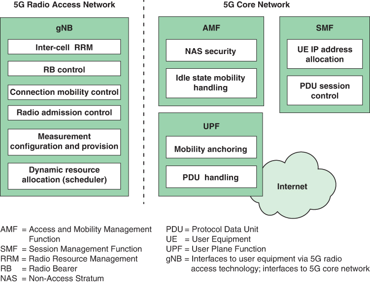
FIGURE 3.9 Functional Split Between NG-RAN and 5G Core Network
RAN Functional Areas
Figure 3.9 illustrates the following key functional areas in the NG-RAN:
Inter-cell radio resource management: Allows the UE to detect neighbor cells, query about the best serving cell, and support the network during handover decisions by providing measurement feedback.
Radio bearer control (RBC): Consists of the procedure for configuration (such as security), establishment, and maintenance of the radio bearer (RB) on both the uplink and downlink with different quality of service (QoS). The term radio bearer refers to an information transmission path of defined capacity, delay, bit error rate, and other parameters.
Connection mobility control (CMC): Functions both in UE idle mode and connected mode. In idle mode, UE is switched on but does not have an established connection. In connected mode, UE is switched on and has an established connection. In idle mode, CMC performs cell selection and reselection. The connected mode involves handover procedures triggered on the basis of the outcome of CMC algorithms.
Radio admission control (RAC): Decides whether a new radio bearer admission request is admitted or rejected. The objective is to optimize radio resource usage while maintaining the QoS of existing user connections. Note that RAC decides on admission or rejection for a new radio bearer, while RBC takes care of bearer maintenance and bearer release operations.
Measurement configuration and provision: Consists of provisioning the configuration of the UE for radio resource management procedures such as cell selection and reselection and for requesting measurement reports to improve scheduling.
Dynamic resource allocation (scheduler): Consists of scheduling RF resources according to their availability on the uplink and downlink for multiple pieces of UE, according to the QoS profiles of a radio bearer.
Access and Mobility Management
On the core network side, the NG-RAN nodes interact with three functions: the access and mobility management, session management, and user plane functions.
The AMF provides UE authentication, authorization, and mobility management services. The two main functions shown in Figure 3.9 for AMF are NAS security and idle state mobility handling.
The non-access stratum (NAS) is the highest protocol layer of the control plane between UE and the access and mobility management function (AMF) in the core network. The main functions of the protocols that are part of the NAS are the support of mobility of the UE and the support of session management procedures to establish and maintain IP connectivity between the UE and user plane function (UPF). It is used to maintain continuous communications with the UE as it moves. In contrast, the access stratum is responsible for carrying information just over the wireless portion of a connection. NAS security involves IP header compression, encryption, and integrity protection of data based on the NAS security keys derived during the registration and authentication procedure.
Idle state mobility handling deals with cell selection and reselection while the UE is in idle mode, as well as reachability determination.
Session Management Function
The two main functions depicted in Figure 3.9 for SMF are UE IP address allocation and PDU session control.
UE IP address allocation assigns an IP address to the UE at the time of session establishment. This ensures the ability to route data packets within the 5G system and also supports data reception and forwarding to outside networks and provides interconnectivity to external packet data networks (PDNs).
In cooperation with the UPF, the SMF establishes, maintains, and releases a PDU session for user data transfer, which is defined as an association between the UE and a data network that provides PDU connectivity.
User Plane Function
The two main functions depicted in Figure 3.9 for UPF are UE IP mobility anchoring and PDU handling.
UE mobility handling deals with ensuring that there is no data loss when there is a connection transfer due to handover that involves changing anchor points.
Once a session is established, the UPF has a responsibility for PDU handling. This includes the basic functions of packet routing, forwarding, and QoS handling.
Session Establishment
TS 23.502 (Technical Specification Group Services and System Aspects; Procedures for the 5G System (5GS); Stage 2 (Release 16), December 2020) defines the session establishment process. Figure 3.10 provides a much simplified view of the interaction between the various network components during session establishment. This section does not examine this process in detail. More detail is provided in Chapter 9.

FIGURE 3.10 UE-Requested PDU Session Establishment
Session establishment begins with a request from the UE over the RAN, which is directed to the AMF. An SMF is selected to manage the PDU session. SMF utilizes UDM in the process of creating a session and performing authentication and authorization. SMF selects a PCF for the session. SMF selects a UPF to handle data plane PDU forwarding in both directions. SMF establishes a session with the DN. After a few more exchanges, the UE is able to communicate over a session with the DN.
3.4 Key Terms and Review Questions
Key Terms
Review Questions
1. List the emerging 5G use cases defined by ITU-R.
2. Explain the use of two dimensions in characterizing 5G uses cases by 5G Americas.
3. Explain the concepts of families and categories used by NGMN to classify 5G use cases.
4. What is softwarization?
5. What are the main approaches to softwarization?
6. Describe the three layers of the NGMN architecture framework.
7. Define the three types of nodes that are used in the NGMN core network model.
8. In the NGMN model, who are the key 5G users?
9. What is the relationship between network slicing and the types of nodes in the core network?
10. Explain the concept of roaming.
11. What is the difference between a service-based representation and a reference point representation?
12. Summarize the major functions encompassed by the user plane function.
13. What are the two primary types of nodes in a radio access network?
14. List and briefly define the RAN functional areas.
15. Which core network functions interact directly with the RAN?
3.5 References and Documents
References
IVES18 Ives, S. “Where Is Video Monitoring Now?” Security Systems News, July 25, 2018.
KABL17 Kablan, M., et al. “Stateless Network Functions: Breaking the Tight Coupling of State and Processing.” Proceedings of the 14th USENIX Symposium on Networked Systems Design and Implementation (NSDI ’17), March 2017.
Documents
3GPP TS 23.501 Technical Specification Group Services and System Aspects; System Architecture for the 5G System (5GS); Stage 2 (Release 16). December 2020.
3GPP TS 23.502 Technical Specification Group Services and System Aspects; Procedures for the 5G System (5GS); Stage 2 (Release 16). December 2020.
3GPP TS 38.300 Technical Specification Group Radio Access Network; NR; NR and NG-RAN Overall Description; Stage 2 (Release 16). December 2020.
5G Americas 5G Services & Use Cases. November 2017.
ITU-R Report M.2441 Emerging Usage of the Terrestrial Component of International Mobile Telecommunication. November 2018.
ITU-T Y.3102 Framework of the IMT-2020 Network. May 2018.
NGMN15 NGMN 5G White Paper. February 2015.
NGMN19 5G End-to-End Architecture Framework. August 2019.