Chapter 7
DMVPN
Introduction to DMVPN
One of the challenges many organizations face is dealing with remote site connectivity. Typically, companies start with a single headquarters office. As the company grows and expands into different locations, these remote locations need to have a means of communicating with each other and the original headquarters location. When sites are geographically separated in such a way, a wide area network (WAN) is needed in order to allow them to interact with each other.
A WAN is a network that spans multiple geographic regions and is typically created by a single service provider or a group of service providers sharing a common interest. The best example of a WAN is the public Internet. The public Internet is a WAN composed of many privately owned organizations and service providers collaborating together to create a global network.
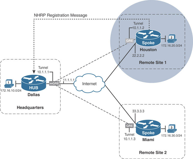
Internet connectivity over the years has moved from being a luxury to being a requirement for continued business operations. It is common for most branch sites to start out with only a single Internet connection in their infancy. Take the example below:
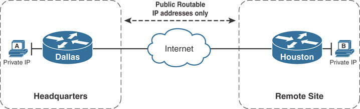
The corporate headquarters office located in Dallas has a remote site located in Houston. Both the headquarters office and remote site have active connections to the public Internet. The company can leverage the existing Internet connection as the WAN transport to exchange information between the networks at the headquarters site and those at the remote site. However, this presents a problem. The public Internet uses public IP addressing, whereas the remote sites use RFC 1918 private addressing. Internet routers are not configured to route RFC 1918 private addresses, which means a packet from Host A in Dallas would not reach Host B in Houston.
Tunneling provides an easy solution to this problem. When the ISP provisions the connection to the Internet, the Dallas and Houston routers are provided with publicly routable IP addressing. Tunneling allows the Dallas router to encapsulate the original IP packet from Host A into an IP packet sourced from Dallas’s public IP address and destined to Houston’s public IP address. This happens by adding an extra IP header to the existing IP packet called an outer header. The resulting packet is an IP packet that contains the original IP packet with the internal addressing as payload.
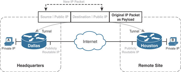
The Internet routers forward the new IP packet just as they would any other traffic, landing it at the Houston router. The Houston router removes the outer IP packet header to expose the original IP packet destined from Host A to Host B. The Houston router can then route the original packet out its LAN interface toward Host B.
What has happened here is that the Dallas and Houston routers have created a virtual network that uses the public Internet as its transport. Such a virtual network is called an overlay network because it is dependent on an underlying transport, called the underlay network. Traffic flowing through the overlay network is forwarded by the underlay network as opaque data. Without the use of protocol analyzers, the underlay network is unaware of the existence of the overlay. The Dallas and Houston routers are considered the endpoints of the tunnel that forms the overlay network.
Many tunneling technologies can be used to form the overlay network. Probably the most widely used is the Generic Routing Encapsulation (GRE) tunnel. A GRE tunnel can support tunneling for a variety of protocols over an IP-based network. It works by inserting an IP and GRE header on top of the original protocol packet, creating a new GRE/IP packet. The resulting GRE/IP packet uses a source/destination pair that is routable over the underlying infrastructure, as described above. The GRE/IP header is known as the outer header, and the original protocol header is the inner header.
In Cisco IOS, GRE tunnels are configured using tunnel interfaces. A tunnel interface is defined and assigned its own unique IP address, which defines the overlay network. It is then configured with appropriate source and destination IP addresses to use for the GRE tunnel’s outer IP header. These addresses should be reachable over the underlay network. For example, if the underlay is provided by the public Internet, then these source and destination addresses should be publicly routable addresses. Typically, the destination IP address should be the address of the remote tunnel endpoint’s interface connected to the underlay network. The tunnel overlay addresses of both endpoints should be in the same subnet.
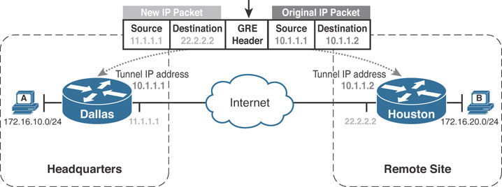
In the following example, the tunnel endpoints on Dallas and Houston form an overlay network in the 10.1.1.0/24 address range. The Dallas router’s IP address on the Internet is 11.1.1.1, and the Houston router’s is 22.2.2.2. The graphic shows a GRE/IP packet sent from Dallas to Houston.
The following commands are used to configure the GRE tunnel between the two routers:
Dallas:
interface tunnel1
 ip address 10.1.1.1 255.255.255.0  ! Dallas’s overlay address
 tunnel source 11.1.1.1             ! Dallas’s underlay address
 tunnel destination 22.2.2.2        ! Houston’s underlay address
Houston:
interface tunnel1
 ip address 10.1.1.2 255.255.255.0  ! Houston’s overlay address
 tunnel source 22.2.2.2             ! Houston’s underlay address
 tunnel destination 11.1.1.1        ! Dallas’s underlay address
After configuring this, a ping through the overlay network between Dallas and Houston results in the following packet:
Internet Protocol Version 4, Src: 11.1.1.1, Dst: 22.2.2.2
Generic Routing Encapsulation (IP)
Internet Protocol Version 4, Src: 10.1.1.1, Dst: 10.1.1.2
Internet Control Message Protocol
Notice the top IP header source, 11.1.1.1. It is the same IP address used in Dallas’s tunnel source command. The destination IP address is 22.2.2.2, which is the IP address used in Dallas’s tunnel destination command. The GRE/IP header uses the values provided from these two commands to build the outer IP header. The next IP header is the original header for ICMP traffic that was delivered through the overlay. 10.1.1.1 is Dallas’s overlay address, and 10.1.1.2 is Houston’s overlay address.
The tunnel is fully functional. Now the Dallas and Houston routers need a way to direct traffic through their tunnels. Dynamic routing protocols such as EIGRP are a good choice for this. By simply enabling EIGRP on the tunnel and LAN interfaces on the router, the routing table is populated appropriately:
Dallas#show ip route | begin Gate
Gateway of last resort is not set

      10.0.0.0/8 is variably subnetted, 2 subnets, 2 masks
C        10.1.1.0/24 is directly connected, Tunnel1
L        10.1.1.1/32 is directly connected, Tunnel1
      11.0.0.0/8 is variably subnetted, 2 subnets, 2 masks
C        11.1.1.0/24 is directly connected, Ethernet0/0
L        11.1.1.1/32 is directly connected, Ethernet0/0
      22.0.0.0/24 is subnetted, 1 subnets
R        22.2.2.0 [120/1] via 11.1.1.2, 00:00:22, Ethernet0/0
      172.16.0.0/16 is variably subnetted, 3 subnets, 2 masks
C        172.16.10.0/24 is directly connected, Loopback1
L        172.16.10.1/32 is directly connected, Loopback1
D        172.16.20.0/24 [90/27008000] via 10.1.1.2, 00:01:03, Tunnel1
The routing entry for the 172.16.20.0/24 network lists the tunnel interface 1 as the exit interface. When Dallas routes a packet destined to this network, it forwards to tunnel interface 1 and performs the encapsulation, as shown previously. The Dallas router then performs an additional routing lookup against the new outer tunnel destination IP address (22.2.2.2 in case of Dallas-to-Houston traffic). The second IP lookup carries the requirement that in order for Dallas to successfully route through the tunnel, it must have a route to the remote tunnel endpoint, Houston. In this example, RIP (shown in red) is being used to exchange underlay routing information between the ISP and the Dallas and Houston routers. Using RIP, Dallas has learned a route to 22.2.2.2, which is Houston’s underlay address.
The result is that connectivity between the LANs succeeds, as evidenced by this traceroute output:
Dallas#traceroute 172.16.20.1

Type escape sequence to abort.
Tracing the route to 172.16.20.1
VRF info: (vrf in name/id, vrf out name/id)
  1 10.1.1.2 1 msec 5 msec 5 msec
Because of the limitation of setting static source and destination addresses, GRE tunnels are by nature point-to-point tunnels. It is not possible to configure a GRE tunnel to have multiple destinations by default. If the goal is only connecting two sites, then a point-to-point GRE tunnel is a great solution. However, as sites are added, additional point-to-point tunnels are required to connect them. Take the example below, where the company in our example has expanded into a second remote site, in Miami.
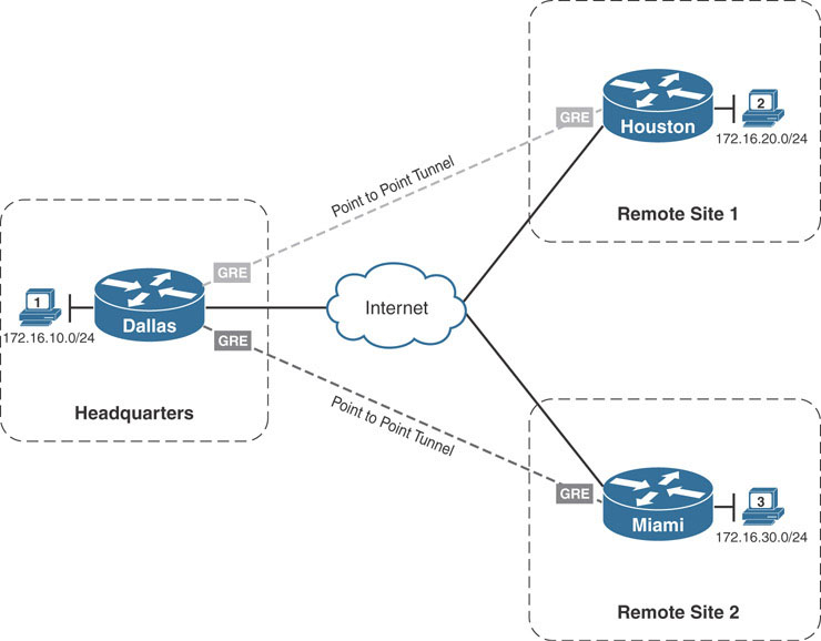
To configure basic connectivity between the two remote sites and the main headquarters site in Dallas, two point-to-point GRE tunnels would need to be configured. In addition, if Houston and Miami required direct communication, a third point-to-point tunnel would be needed. If more sites are added, the number of tunnels grows along with them. In addition to configuring more tunnels, the company would need to ensure that each tunnel exists in a separate subnet, creating multiple isolated overlay networks.
An alternative to configuring multiple point-to-point GRE tunnels is to use multipoint GRE tunnels to provide the connectivity desired.
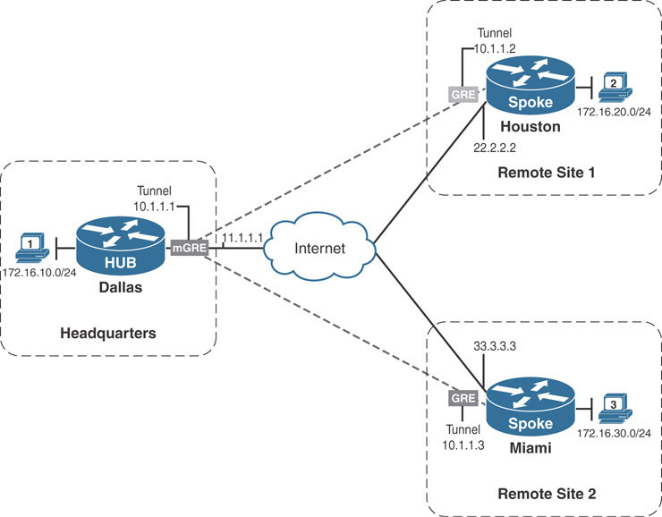
Multipoint GRE (mGRE) tunnels are similar in construction to point-to-point GRE tunnels with the exception of one command: the tunnel destination command. Instead of declaring a static destination, no destination is declared, and instead the tunnel mode gre multipoint command is issued, as shown in the example below (on the Dallas router):
Dallas:
interface tunnel1
 ip address 10.1.1.1 255.255.255.0
 tunnel source 11.1.1.1
 tunnel destination 22.2.2.2  ! static destination removed
 tunnel mode gre multipoint
How does Dallas know what destination to set for the GRE/IP packet created by the tunnel interface? The easy answer is that, on its own, there is no way for Dallas to glean the destination address without the help of an additional protocol, such as Next Hop Resolution Protocol (NHRP). NHRP was originally designed to allow routers connected to non-broadcast multiple-access (NBMA) networks to discover the proper next-hop mappings to communicate together. It is specified in RFC 2332. NBMA networks faced a similar issue as mGRE tunnels. In broadcast networks, protocols such as ARP use broadcast or multicast messages to dynamically discover endpoints on the network.
The best example of this is on Ethernet-based networks. Before a station can send to a remote station, it needs to know the MAC address of the remote station to build the Ethernet frame. ARP provides a means by which the sending station can discover and map the Layer 3 address of the receiving station to the receiving station’s MAC address, using broadcast packets. This exchange is made possible because Ethernet infrastructure devices (namely switches) provide a means by which a single message can be sent from one station and replicated to all stations connected to the LAN.
In NBMA networks, there is no mechanism for doing this. For example, Dallas cannot simply send a broadcast out of the tunnel interface to dynamically discover the Houston router’s address in the underlay for two reasons:
In order to encapsulate the broadcast using the tunnel interface, Dallas needs to have a destination address for the outer GRE/IP packet.
Even if Dallas placed a broadcast address in the destination of the IP packet, the underlay network (the public Internet in this case) does not support replication of broadcast packets. The ISP router would simply drop the traffic.
Looking at the two points above, it becomes apparent that by converting the point-to-point GRE tunnel to an mGRE tunnel, the 10.1.1.0/24 overlay network has become an NBMA network. Without the ability to support broadcast communication on the overlay, routers are unable to support broadcast-based network discovery protocols such as ARP, dynamic routing protocol hello messages, and the like. Missing this ability severely stunts the usefulness of mGRE with regard to dynamic scalability. However, with the overlay functioning as an NBMA network, NHRP can step in to glue it back together.
NHRP accomplishes this by keeping a mapping table of Layer 3 overlay addresses to Layer 3 underlay address pairs. For example, the NHRP table on Dallas would include a mapping of 10.1.1.2/22.2.2.2 for the Houston router. When traffic is forwarded out the mGRE interface on Dallas with NHRP configured, Dallas can consult its NHRP table to find the appropriate tunnel destination.
This solution solves the problem of where Dallas can get the information needed to route the packet, but it does not solve how it receives the information. To do so, NHRP organizes the routers connected to the same NHRP NBMA domain into one of two categories. They are either next hop servers (NHSs) or next hop clients (NHCs). An NHC is configured with the overlay address of the router acting as the NHS. When a client comes online in an NHRP-enabled NBMA network, it first advertises its own overlay-to-underlay mapping to its configured NHS by using a special NHRP registration message. The registration message includes the NHC’s overlay and NBMA network layer addressing information. The NHS receives and stores this information in its NHRP table.
All active clients attached to the NHRP-enabled NBMA must register with the NHS. When the client needs to send traffic to another router attached to the NBMA network, the client can send an NHRP resolution message to the NHS router (for which it already has a static mapping), requesting the appropriate mapping information. If the intended router is online, it is in one of two states: It has registered with an NHS (meaning it is a client), or it is an NHS (and contains the appropriate mapping table). In either case, the sending client can logically consult the NHS for the mapping information with a high probability of receiving a reply.
The NHS forwards this resolution request to the proper client, which responds directly to the querying client.
Note
In previous implementations of NHRP on Cisco IOS, the NHS would respond directly to the requesting client. This functionality was changed in later releases as an enhancement to support hierarchical DMVPN setups.
The collection of routers that share NHRP information is known as an NHRP domain. An NHRP domain is identified by its NHRP network identifier, which is a configurable numeric value. All routers must be configured with an NHRP network identifier in order to process NHRP messages. Doing so allows the router to correlate received NHRP information on multiple interfaces with a specific NHRP domain. This allows multiple interfaces to participate in the same or different NHRP domains as the design requires. The NHRP network identifier is a locally significant value that does NOT have to match between two routers.
To fix the tunnel configuration on the Dallas router, NHRP should be configured on the Dallas and Houston routers. NHS routers should have connectivity to all spokes they will service. Looking at the diagram, the Miami and Houston routers both have GRE tunnel connectivity to the Dallas router. With this information, it makes sense to designate the Dallas router as the NHS for the NHRP domain.
The Houston router is configured with the ip nhrp nhs 10.1.1.1 command to designate the Dallas router as the proper NHS. Both routers use the ip nhrp network-id 1 command to enable NHRP messaging on the tunnel interfaces:
Dallas:
interface Tunnel1
 ip address 10.1.1.1 255.255.255.0
 ip nhrp network-id 1

 tunnel source 11.1.1.1
 tunnel mode gre multipoint
end
Houston:
interface Tunnel1
 ip address 10.1.1.2 255.255.255.0
 ip nhrp network-id 1
 ip nhrp nhs 10.1.1.1 ! Overlay address of Dallas, the NHS
 tunnel source 22.2.2.2
 tunnel destination 11.1.1.1
end
Now a ping through the overlay between Dallas and Houston is successful:
Dallas#ping 10.1.1.2
Type escape sequence to abort.
Sending 5, 100-byte ICMP Echos to 10.1.1.2, timeout is 2 seconds:
!!!!!
The ping succeeds because Dallas has the necessary overlay-to-underlay mapping information in its NHRP mapping table. The contents of the NHRP mapping table can be displayed using the show ip nhrp command:
Dallas#show ip nhrp
10.1.1.2/32 via 10.1.1.2 ! Overlay address of Houston
   Tunnel1 created 00:05:15, expire 01:55:29
   Type: dynamic, Flags: unique registered used nhop
   NBMA address: 22.2.2.2 ! Underlay address of Houston
Note
Houston’s NHRP mapping table will be empty. Because it uses a point-to-point GRE tunnel, there is no need for it to store overlay-to-underlay mappings. Its tunnel can only be routed directly to Dallas.
Communication between Dallas and Houston’s overlay address is successful, but the communication between their LAN interfaces is not. The routing table on Dallas shown below no longer lists the 172.16.20.0/24 network. EIGRP is still configured on the interfaces, but EIGRP prefixes are not being exchanged.
Dallas#show ip route | begin Gate
Gateway of last resort is not set

      10.0.0.0/8 is variably subnetted, 2 subnets, 2 masks
C        10.1.1.0/24 is directly connected, Tunnel1
L        10.1.1.1/32 is directly connected, Tunnel1
      11.0.0.0/8 is variably subnetted, 2 subnets, 2 masks
C        11.1.1.0/24 is directly connected, Ethernet0/0
L        11.1.1.1/32 is directly connected, Ethernet0/0
      22.0.0.0/24 is subnetted, 1 subnets
R        22.2.2.0 [120/1] via 11.1.1.2, 00:00:04, Ethernet0/0
      33.0.0.0/24 is subnetted, 1 subnets
R        33.3.3.0 [120/1] via 11.1.1.2, 00:00:04, Ethernet0/0
      172.16.0.0/16 is variably subnetted, 2 subnets, 2 masks
C        172.16.10.0/24 is directly connected, Loopback1
L        172.16.10.1/32 is directly connected, Loopback1
Adding to the difficulties, the EIGRP neighborship between Dallas and Houston is flapping on the Dallas side:
Dallas:
%DUAL-5-NBRCHANGE: EIGRP-Ipv4 1: Neighbor 10.1.1.2 (Tunnel1) is up:
new adjacency

%DUAL-5-NBRCHANGE: EIGRP-Ipv4 1: Neighbor 10.1.1.2 (Tunnel1) is down:
retry limit exceeded

%DUAL-5-NBRCHANGE: EIGRP-Ipv4 1: Neighbor 10.1.1.2 (Tunnel1) is up:
new adjacency
The reason for this is that while NHRP has filled in to provide the tunnel destination, it still has not solved the underlying problem of the overlay being an NBMA network. EIGRP hello messages are multicast between routers. Taking an example of two routers (R1 and R2), the basic EIGRP neighborship process is as follows:
R1 and R2 exchange multicast hello messages.
R2 receives the hello message and creates a neighbor entry for R1 in its neighbor table in the “pending” state.
R2 sends a unicast update message with the “init” bit set to accelerate the hello process.
R1 receives the update message with the “init” bit set and sends back an acknowledgment packet.
Steps 2–4 are repeated but in reverse.
The neighborship is established, and the two routers begin exchanging prefixes.
Through this sequence, both multicast and unicast connectivity is verified between the two EIGRP routers. When the neighborship process above is applied to the mGRE interface on the Dallas router, the Dallas router is unable to tunnel hello packets to the Houston router because the destination address for EIGRP hello packets is 224.0.0.10.
IP addresses in that range are called multicast IP addresses. Typically, when EIGRP is enabled on an interface, the router can encode the Ethernet frame with a multicast MAC address that signifies to intermediate devices that this traffic should be forwarded out all switch ports in the same VLAN, much like a broadcast packet. The problem Dallas is facing is that EIGRP is enabled on its mGRE interface. Because the interface is mGRE, Dallas does not have a hard-coded destination address for the GRE/IP header, as explained earlier. As a result, Dallas cannot encode the GRE/IP packet to tunnel the multicast traffic across the underlay. The following events occur:
Houston sends a hello packet to Dallas. It can do so because it has a point-to-point GRE tunnel. All traffic through the tunnel goes to Dallas as the statically configured tunnel destination.
Dallas receives the hello, initiates the neighbor structure, and sends a unicast update message with the init bit set to Houston.
Because Houston has not received a hello packet from Dallas, it does not accept its update packet.
Dallas waits to receive an acknowledgment for its update packet sent to Houston and receives none.
Dallas clears the neighbor entry for Houston.
Houston sends another hello packet to Dallas.
This cycle repeats until Dallas is able to send a multicast hello to Houston. Specifically, because Houston never receives a multicast packet from Dallas (it only receives a unicast packet at step 2), Houston always rejects Dallas’s update packet. Dallas can never send a multicast hello packet to Houston because it does not have sufficient forwarding information (that is, destination NBMA address) to send the multicast through its mGRE interface.
Dallas needs a mechanism by which it can associate multicast traffic with a specific NBMA address in order to send the multicast as unicast over the underlay. NHRP solves this problem by storing a separate NHRP table specifically for multicast traffic. This table lists all of the underlay addresses to which multicast traffic should be sent. When the router needs to forward multicast packets out of an NHRP-enabled interface, it replicates the packet as unicast toward each underlay address in the NHRP multicast table. This process, often referred to as pseudo-multicasting, is very similar to Frame Relay pseudo-multicasting in Frame Relay hub-and-spoke topologies.
The NHRP multicast table can be configured statically using ip nhrp map multicast underlay-ip-address command. Such a configuration is tedious on an NHS because there is no telling how many NHRP clients will register mappings with the NHS. So instead, the ip nhrp map multicast dynamic command tells the NHS to automatically add a dynamic NHRP multicast entry for every client that registers with the NHS. To solve the connectivity issues between Dallas and Houston, this command is configured on Dallas. Then, the tunnel interface on Houston is flapped to force it to re-register with Dallas. The show ip nhrp multicast command verifies the multicast entry on the Dallas router. The EIGRP neighbors come up, and pings are successful between the LAN interfaces again:
Dallas#show run interface tunnel1

interface Tunnel1
 ip address 10.1.1.1 255.255.255.0
 no ip redirects
 ip nhrp map multicast dynamic
 ip nhrp network-id 1
 tunnel source 11.1.1.1
 tunnel mode gre multipoint

Houston(config)#interface tunnel1
Houston(config-if)#shut

%LINEPROTO-5-UPDOWN: Line protocol on Interface Tunnel1, changed state
to down
%LINK-5-CHANGED: Interface Tunnel1, changed state to
administratively down

Houston(config-if)#no shut

%LINEPROTO-5-UPDOWN: Line protocol on Interface Tunnel1, changed state
to up
%LINK-3-UPDOWN: Interface Tunnel1, changed state to up

%DUAL-5-NBRCHANGE: EIGRP-Ipv4 1: Neighbor 10.1.1.2 (Tunnel1) is up:
new adjacency

Dallas#show ip nhrp multicast

  I/F     NBMA address
Tunnel1    22.2.2.2        Flags: dynamic          (Enabled)

Dallas#show ip route 172.16.20.0
Routing entry for 172.16.20.0/24
  Known via "eigrp 1", distance 90, metric 27008000, type internal

  Redistributing via eigrp 1
  Last update from 10.1.1.2 on Tunnel1, 00:00:13 ago
  Routing Descriptor Blocks:
  * 10.1.1.2, from 10.1.1.2, 00:00:13 ago, via Tunnel1
      Route metric is 27008000, traffic share count is 1
      Total delay is 55000 microseconds, minimum bandwidth is 100 Kbit
      Reliability 255/255, minimum MTU 1476 bytes
      Loading 1/255, Hops 1

Dallas#ping 172.16.20.1 source 172.16.10.1

Type escape sequence to abort.
Sending 5, 100-byte ICMP Echos to 172.16.20.1, timeout is 2 seconds:
Packet sent with a source address of 172.16.10.1
!!!!!
Taking a step back can help you understand what this seemingly complex configuration has accomplished: Before, static point-to-point GRE tunnels, each representing a separate subnet, were required to form the overlay necessary to connect the Dallas and Houston sites. When the Miami site was added, another tunnel was required to connect Miami to Dallas and, if necessary, to connect Miami with Houston.
The mGRE/NHRP configuration outlined allows only a single tunnel interface to be required per router in order to connect Dallas to Houston and Dallas to Miami. All Miami needs is a point-to-point GRE interface configured with Dallas as the NHRP NHS, and connectivity will be established. Through EIGRP, Miami can also receive routes for the networks behind Dallas as well. Most importantly, the tunnel interfaces on Dallas, Houston, and Miami are all part of the same IP subnet and participate in the same NHRP domain.
The total configuration on Miami to join it to the cloud and the appropriate verification commands are as follows:
Miami:
interface Tunnel1
 ip address 10.1.1.3 255.255.255.0
 ip nhrp network-id 1
 ip nhrp nhs 10.1.1.1
 tunnel source 33.3.3.3
 tunnel destination 11.1.1.1
end
!
router eigrp 1
 network 10.1.1.0 0.0.0.255

 network 172.16.30.0 0.0.0.255

Miami#show ip route | begin Gate
Gateway of last resort is not set

      10.0.0.0/8 is variably subnetted, 2 subnets, 2 masks
C        10.1.1.0/24 is directly connected, Tunnel1
L        10.1.1.3/32 is directly connected, Tunnel1
      11.0.0.0/24 is subnetted, 1 subnets
R        11.1.1.0 [120/1] via 33.3.3.1, 00:00:16, Ethernet0/0
      22.0.0.0/24 is subnetted, 1 subnets
R        22.2.2.0 [120/1] via 33.3.3.1, 00:00:16, Ethernet0/0
      33.0.0.0/8 is variably subnetted, 2 subnets, 2 masks
C        33.3.3.0/24 is directly connected, Ethernet0/0
L        33.3.3.3/32 is directly connected, Ethernet0/0
      172.16.0.0/16 is variably subnetted, 3 subnets, 2 masks
D        172.16.10.0/24 [90/27008000] via 10.1.1.1, 00:00:12, Tunnel1
C        172.16.30.0/24 is directly connected, Loopback1
L        172.16.30.1/32 is directly connected, Loopback1

Miami#ping 172.16.10.1 source 172.16.30.1

Type escape sequence to abort.
Sending 5, 100-byte ICMP Echos to 172.16.10.1, timeout is 2 seconds:
Packet sent with a source address of 172.16.30.1
!!!!!
In the routing table output above, you can see that Miami receives a route for the LAN behind Dallas (the 172.16.10.0/24 network) but not for the Houston LAN (172.16.20.0/24 network). Dallas appears to not be advertising the Houston LAN to Miami. This reason is not unknown to Distance Vector protocols as it is caused by a concept known as split horizon. Split horizon prevents a router from advertising a route for a prefix out the same interface the router uses to reach that prefix. In Dallas’s case, it learns the 172.16.20.0/24 route from Houston, which is connected to its tunnel interface. It cannot advertise that same network toward Miami out the same tunnel 1 interface.
To alleviate the problem here, split horizon can be disabled on the tunnel interface of Dallas with the no ip split-horizon eigrp command. Notice that Miami now learns of the LAN network behind Houston:
Dallas(config)#interface tunnel1
Dallas(config-if)#no ip split-horizon eigrp 1


%DUAL-5-NBRCHANGE: EIGRP-IPv4 1: Neighbor 10.1.1.3 (Tunnel1) is
resync: split horizon changed

Miami#show ip route eigrp | begin Gateway
Gateway of last resort is not set

      172.16.0.0/16 is variably subnetted, 4 subnets, 2 masks
D        172.16.10.0/24 [90/27008000] via 10.1.1.1, 00:06:57, Tunnel1
D        172.16.20.0/24 [90/28288000] via 10.1.1.1, 00:01:07, Tunnel1
A ping between the LAN interfaces of Miami and Houston confirms the connectivity:
Miami#ping 172.16.20.1 source 172.16.30.1

Type escape sequence to abort.
Sending 5, 100-byte ICMP Echos to 172.16.20.1, timeout is 2 seconds:
Packet sent with a source address of 172.16.30.1
!!!!!
The mGRE/NHRP solution reduces the configuration complexity to something that can be easily scripted out using various tools. Adding a new site to the existing VPN only requires direct configuration of the new devices. The devices come online, register with Dallas, receive their routing updates, and are ready to participate in the overlay network without the need to consult a service provider to provision private WAN circuits.
Using mGRE and NHRP in this way forms the underlying architecture that powers the Dynamic Multipoint VPN (DMVPN) solution. The routers above are actually participating in a DMVPN cloud. It is dynamic because routers can be added or removed with minimal configuration. It is multipoint because Dallas, as the NHS, can form tunnels to all clients that register with it, using a single multipoint GRE tunnel interface. It is virtually private because it is tunneled over an existing underlay, presenting the illusion of direct connectivity for all of the devices involved.
DMVPN Mechanics
The section above outlines the use case that DMVPN was created to solve. It also introduces the symbiotic relationship between NHRP and mGRE that forms the building blocks for a DMVPN cloud. This section delves a bit more deeply into the operation and mechanics of a DMVPN cloud.
Although DMVPN uses NHRP for its address resolution, it does not borrow from NHRP terminology but instead uses its own. DMVPN clouds are constructed as hub-and-spoke topologies. In a hub-and-spoke topology, networking devices (the spokes) connect through a common, shared network device that acts as the aggregation point for the topology. This common point is termed the hub of the hub-and-spoke network.
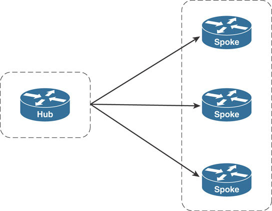
DMVPN clouds are, at their core, hub-and-spoke networks. The DMVPN hub router acts as the central aggregation point for all of the spoke routers that connect to it in its DMVPN cloud. In the NHRP network created in the first section, the Dallas router is considered the hub of the DMVPN cloud, and Houston and Miami routers are the spokes.
This distinction is important as hubs and spokes have different responsibilities within the DMVPN cloud. DMVPN hub routers also act as NHRP NHS routers that store and receive mapping information from the NHCs. DMVPN spoke routers are the NHRP NHCs, which send their mapping information to a hub router that acts as the spoke routers’ NHSs. In the example above, Houston and Miami are the spoke routers that send their NHRP mapping information to the hub router Dallas, through a process called NHRP registration.
Going back in time to a point where both Dallas and Houston were first configured and following the entire registration process will help you gain a better understanding of the NHRP registration process. Recall the following configurations on the Dallas and Houston routers from the section above:
On Hub—Dallas:
interface Tunnel1
 ip address 10.1.1.1 255.255.255.0
 no ip split-horizon eigrp 1
 ip nhrp map multicast dynamic
 ip nhrp network-id 1
 tunnel source 11.1.1.1
 tunnel mode gre multipoint
On Spoke—Houston:
interface Tunnel1
 ip address 10.1.1.2 255.255.255.0
 ip nhrp network-id 1
 ip nhrp nhs 10.1.1.1
 tunnel source 22.2.2.2
 tunnel destination 11.1.1.1
Dallas is configured with an mGRE tunnel, while Houston is configured with a point-to-point GRE tunnel. EIGRP is also configured to run on the tunnel interfaces of the routers. Finally, EIGRP’s split-horizon feature has been disabled on the tunnel interface on Dallas.
Recall that with Dallas being configured with an mGRE tunnel interface, there is no tunnel destination configured for the GRE tunnel interface to use in its GRE tunnel IP header. Without this information, Dallas cannot forward traffic to Houston in the overlay, as evidenced by the unsuccessful ping output below:
Dallas#ping 10.1.1.2

Type escape sequence to abort.

Sending 5, 100-byte ICMP Echos to 10.1.1.2, timeout is 2 seconds:
.....
Success rate is 0 percent (0/5)
NHRP steps in to provide this information by maintaining an NBMA-to-overlay IP address mapping table on the router. This NHRP mapping table is consulted to fill in the required information when sending packets across the DMVPN network.
Just as static routes can be configured for the IP routing table, the NHRP mapping table can be populated using static NHRP mapping command (ip nhrp map). However, populating the mapping table this way carries the same drawbacks at scale as configuring static routes. The configuration complexity grows as many more spokes are connected to the same hub router.
The designers of DMVPN take advantage of the NHS/NHC relationship to allow the spokes to dynamically register their NHRP mapping information with the hub routers. Spokes are configured with the ip nhrp nhs command, which identifies which router functions as the NHS.
In the example topology, Dallas is the hub of the DMVPN and therefore is also the NHS for the NHRP network. Once Houston comes online, it first sends an NHRP registration request to Dallas in order to register its NBMA-to-overlay address mapping.
With the help of the debug nhrp packet and debug nhrp detail commands on both Dallas and Houston, the registration process can be observed in real time. Once Houston’s tunnel interface comes online, Houston sends an NHRP registration packet to Dallas. It knows Dallas is the NHS because Dallas’s IP address is identified in the ip nhrp nhs 10.1.1.1 command on Houston’s tunnel interface. This NHRP registration packet is shown in the debugging output below:
Houston:
 NHRP: Send Registration Request via Tunnel1 vrf 0, packet size: 88
  src: 10.1.1.2, dst: 10.1.1.1
  (F) afn: AF_IP(1), type: IP(800), hop: 255, ver: 1
      shtl: 4(NSAP), sstl: 0(NSAP)
      pktsz: 88 extoff: 52
  (M) flags: "unique nat ", reqid: 11
      src NBMA: 22.2.2.2
      src protocol: 10.1.1.2, dst protocol: 10.1.1.1
  (C-1) code: no error(0)
        prefix: 32, mtu: 17916, hd_time: 7200
The first two lines of the debugging output indicate that an NHRP registration request packet is being sent to 10.1.1.1 (NHS). The source of the packet is 10.1.1.2 (Houston’s tunnel address). The mapping information is split in the src NBMA and src protocol fields of the registration packet. The src NBMA field indicates the NBMA address of the device that is sending the NHRP registration request. In this case, Houston’s NBMA address is 22.2.2.2, the address configured as the tunnel source address of its GRE interface connected to the DMVPN. The src protocol address is the overlay IP address of the device sending the registration request. For Houston, this address is its tunnel interface address 10.1.1.2, which is the tunnel IP address assigned to Houston’s GRE interface connected to the DMVPN.
These pieces of information combined are received on the hub router, Dallas, as shown below:
NHRP: Receive Registration Request via Tunnel1 vrf 0, packet size: 88
  (F) afn: AF_IP(1), type: IP(800), hop: 255, ver: 1
      shtl: 4(NSAP), sstl: 0(NSAP)
      pktsz: 88 extoff: 52
  (M) flags: "unique nat ", reqid: 11
      src NBMA: 22.2.2.2
      src protocol: 10.1.1.2, dst protocol: 10.1.1.1
  (C-1) code: no error(0)

  prefix: 32, mtu: 17916, hd_time: 7200
        addr_len: 0(NSAP), subaddr_len: 0(NSAP), proto_len: 0, pref: 0
 NHRP: Adding Tunnel Endpoints (VPN: 10.1.1.2, NBMA: 22.2.2.2)
 NHRP: Successfully attached NHRP subblock for Tunnel Endpoints (VPN:
10.1.1.2, NBMA: 22.2.2.2)
Once Dallas receives the mapping, it adds the information to the NHRP mapping table. Notice that the debugging output above indicates the VPN address as 10.1.1.2 for Houston. In this context, VPN indicates the overlay protocol address for the DMVPN.
The resulting mapping on Dallas can be verified using the show ip nhrp and show dmvpn commands on Dallas:
Dallas#show ip nhrp

10.1.1.2/32 via 10.1.1.2
   Tunnel1 created 00:55:33, expire 01:44:27
   Type: dynamic, Flags: unique registered used nhop
   NBMA address: 22.2.2.2

Dallas#show dmvpn

Legend: Attrb --> S - Static, D - Dynamic, I - Incomplete
        N - NATed, L - Local, X - No Socket
        # Ent --> Number of NHRP entries with same NBMA peer
        NHS Status: E --> Expecting Replies, R --> Responding, W -->
Waiting
        UpDn Time --> Up or Down Time for a Tunnel
====================================================================

Interface: Tunnel1, IPv4 NHRP Details
Type:Hub, NHRP Peers:1,

 # Ent  Peer NBMA address Peer Tunnel Add State  UpDn Tm Attrb
 ----- --------------- --------------- ----- -------- -----
     1 22.2.2.2               10.1.1.2    UP 01:02:32     D
The show ip nhrp output lists the mapping information for the 10.1.1.2/32 address on the overlay network. The NBMA address is listed as 22.2.2.2, and it is flagged as a dynamic entry because it was added as a result of the NHRP registration process.
The show dmvpn output shows the entry with the NBMA address 22.2.2.2 as the Peer NBMA address and the overlay address 10.1.1.2 as the Peer Tunnel Add. It lists the state of the tunnel as UP. The tunnel itself can be in many other states, depending on which part of the NHRP registration process the entry is currently going through. The last column, the Attrb column, signifies that the entry was created dynamically.
In response to the NHRP registration request from Houston, Dallas replies to Houston with an NHRP registration reply message. The exchange is shown below:
On Dallas:
 NHRP: Attempting to send packet through interface Tunnel1 via DEST
dst 10.1.1.2
 NHRP: Send Registration Reply via Tunnel1 vrf 0, packet size: 108
  src: 10.1.1.1, dst: 10.1.1.2
  (F) afn: AF_IP(1), type: IP(800), hop: 255, ver: 1
      shtl: 4(NSAP), sstl: 0(NSAP)
      pktsz: 108 extoff: 52
  (M) flags: "unique nat ", reqid: 11
      src NBMA: 22.2.2.2
      src protocol: 10.1.1.2, dst protocol: 10.1.1.1
  (C-1) code: no error(0)
        prefix: 32, mtu: 17916, hd_time: 7200
        addr_len: 0(NSAP), subaddr_len: 0(NSAP), proto_len: 0, pref: 0
 NHRP: Encapsulation succeeded.  Sending NHRP Control Packet  NBMA
Address: 22.2.2.2
 NHRP: 132 bytes out Tunnel1
On Houston:
 NHRP: Receive Registration Reply via Tunnel1 vrf 0, packet size: 108
  (F) afn: AF_IP(1), type: IP(800), hop: 255, ver: 1
      shtl: 4(NSAP), sstl: 0(NSAP)
      pktsz: 108 extoff: 52
  (M) flags: "unique nat ", reqid: 11
      src NBMA: 22.2.2.2
      src protocol: 10.1.1.2, dst protocol: 10.1.1.1
  (C-1) code: no error(0)
When the process is complete, Houston has successfully registered with Dallas. Dallas has been configured with an mGRE tunnel interface. There is no tunnel destination configured for the GRE tunnel interface to use in its GRE tunnel IP header. With Houston registered, Dallas now has sufficient information to forward packets out its tunnel interface to Houston. The successful ping below demonstrates communication between Dallas and Houston:
Dallas#ping 10.1.1.2

Type escape sequence to abort.
Sending 5, 100-byte ICMP Echos to 10.1.1.2, timeout is 2 seconds:
!!!!!
Success rate is 100 percent (5/5), round-trip min/avg/max = 1/4/5 ms
Adding a new spoke to the DMVPN is as simple as pasting the same configuration template from Houston on router Miami, taking care to change the tunnel IP address and tunnel source address accordingly:
On Miami:
interface Tunnel1
 ip address 10.1.1.3 255.255.255.0
 ip nhrp network-id 1
 ip nhrp nhs 10.1.1.1
 tunnel source 33.3.3.3
 tunnel destination 11.1.1.1
The output of the show dmvpn command from the hub Dallas verifies that the spoke Miami has registered with it dynamically as well. A ping from Dallas to Miami’s tunnel IP address is also shown to succeed:
Dallas#show dmvpn

Legend: Attrb --> S - Static, D - Dynamic, I - Incomplete
        N - NATed, L - Local, X - No Socket
        # Ent --> Number of NHRP entries with same NBMA peer
        NHS Status: E --> Expecting Replies, R --> Responding, W -->
Waiting
        UpDn Time --> Up or Down Time for a Tunnel
=====================================================================

Interface: Tunnel1, IPv4 NHRP Details
Type:Hub, NHRP Peers:2,


 # Ent  Peer NBMA address Peer Tunnel Add State  UpDn Tm Attrb
 ----- --------------- --------------- ----- -------- -----
     1 22.2.2.2               10.1.1.2    UP 01:10:58     D
     1 33.3.3.3               10.1.1.3    UP 00:00:07     D

Dallas#ping 10.1.1.3

Type escape sequence to abort.
Sending 5, 100-byte ICMP Echos to 10.1.1.3, timeout is 2 seconds:
!!!!!
Success rate is 100 percent (5/5), round-trip min/avg/max = 1/4/5 ms
The DMVPN hub router is not only responsible for the NHRP mapping table but also for the exchange of routing information between the spokes. Above, EIGRP is used as the routing protocol of choice and is enabled on the tunnel interfaces. EIGRP multicast hello packets discover neighbors. In the previous section, these multicasts needed a proper NBMA address to be pseudo-multicasted over the overlay.
NHRP fills this gap in as well by maintaining a multicast mapping table. This table can also be populated dynamically or statically. In DMVPN, routing protocol multicasts are sent only between the hub and spoke routers. This means the spokes need an NHRP multicast mapping only for the hub—and not for the other spokes. It also means the hub router requires an NHRP multicast mapping for every spoke that registers with it on the DMVPN cloud. This information too can be dynamically filled in at the same time the hub creates the dynamic NHRP mapping for NBMA-to-overlay addressing through the ip nhrp map multicast dynamic command.
Note
In the case where the spokes are configured with point-to-point GRE tunnels, there is no need to configure the NHRP multicast mapping on the spokes. A point-to-point GRE tunnel has only one destination, to which all packets can be sent: a destination that is hard coded as the tunnel destination configuration under the tunnel interface. Therefore, multicast traffic can always be sent out the point-to-point tunnel interfaces to this destination address. This is the case above, where the spokes have point-to-point GRE tunnels configured and the hub uses the mGRE tunnel.
However, multicast mappings would be required in cases where the spokes also use mGRE interfaces—specifically in DMVPN Phase 2 and Phase 3 designs.
With the ip nhrp map multicast dynamic command configured on the tunnel interface on Dallas, whenever a spoke registers with Dallas, it automatically adds the spoke’s NBMA address to its NHRP multicast table. The output below from debug nhrp detail was taken when Houston first registered with Dallas. The show ip nhrp multicast command confirms the mapping:
On Dallas:
 NHRP: Tu1: Creating dynamic multicast mapping  NBMA: 22.2.2.2
 NHRP: Added dynamic multicast mapping for NBMA: 22.2.2.2

Dallas#show ip nhrp multicast

  I/F     NBMA address
Tunnel1    22.2.2.2        Flags: dynamic          (Enabled)
The same occurs for Miami. With EIGRP configured on the tunnel interfaces, EIGRP packets (multicast and unicast) will now be encapsulated within GRE and unicasted to the NBMA addresses of Houston and Miami by Dallas. The following captures show an example of such packets transmitted by Dallas to the spokes, Houston and Miami.
Frame 32: 98 bytes on wire (784 bits), 98 bytes captured (784 bits) on
interface 0
Ethernet II, Src: aa:bb:cc:00:01:00 (aa:bb:cc:00:01:00), Dst:
aa:bb:cc:00:04:00 (aa:bb:cc:00:04:00)
Internet Protocol Version 4, Src: 11.1.1.1, Dst: 22.2.2.2
Generic Routing Encapsulation (IP)
Internet Protocol Version 4, Src: 10.1.1.1, Dst: 224.0.0.10
Cisco EIGRP

Frame 33: 98 bytes on wire (784 bits), 98 bytes captured (784 bits) on
interface 0
Ethernet II, Src: aa:bb:cc:00:01:00 (aa:bb:cc:00:01:00), Dst:
aa:bb:cc:00:04:00 (aa:bb:cc:00:04:00)
Internet Protocol Version 4, Src: 11.1.1.1, Dst: 33.3.3.3
Generic Routing Encapsulation (IP)
Internet Protocol Version 4, Src: 10.1.1.1, Dst: 224.0.0.10
Cisco EIGRP
EIGRP relationships are then formed between Dallas and the spokes, Houston and Miami. The show ip eigrp neighbors command output on Dallas verifies these EIGRP neighborships:
Houston:
Houston#show ip eigrp neighbors
EIGRP-IPv4 Neighbors for AS(1)
H   Address         Interface    Hold Uptime   SRTT   RTO  Q  Seq
                                    (sec)         (ms)       Cnt Num
1   10.1.1.3         Tu1             12 00:09:20    5  1470  0  3
0   10.1.1.2         Tu1             12 00:19:36   13  1470  0  7
On completing the above configurations, the routing tables on Houston and Miami confirm that they have EIGRP routes of each other’s LAN networks. A ping is issued between the LANs on Houston and Miami to confirm the communication:
On Houston:
Houston#show ip route eigrp | begin Gate
Gateway of last resort is not set

    172.16.0.0/16 is variably subnetted, 4 subnets, 2 masks
D    172.16.10.0/24 [90/27008000] via 10.1.1.1, 00:21:39, Tunnel1
D    172.16.30.0/24 [90/28288000] via 10.1.1.1, 00:11:23, Tunnel1
On Miami:
Miami#show ip route eigrp | begin Gate
Gateway of last resort is not set

    172.16.0.0/16 is variably subnetted, 4 subnets, 2 masks
D     172.16.10.0/24 [90/27008000] via 10.1.1.1, 00:11:40, Tunnel1
D     172.16.20.0/24 [90/28288000] via 10.1.1.1, 00:11:40, Tunnel1
On Houston:
Houston#ping 172.16.30.1 source 172.16.20.1

Type escape sequence to abort.
Sending 5, 100-byte ICMP Echos to 172.16.30.1, timeout is 2 seconds:
Packet sent with a source address of 172.16.20.1
!!!!!
Success rate is 100 percent (5/5), round-trip min/avg/max = 1/4/5 ms
DMVPN Designs
The word phase is almost always connected to DMVPN design discussions. DMVPN phase refers to the version of DMVPN implemented in a DMVPN design. DMVPN as a solution was rolled out in different stages as the solution became more widely adopted to address performance issues and additional improvised features. There are three main phases for DMVPN:
Phase 1 - Hub-and-spoke
Phase 2 - Spoke-initiated spoke-to-spoke tunnels
Phase 3 - Hub-initiated spoke-to-spoke tunnels
The differences between the DMVPN phases are related to routing efficiency and the ability to create spoke-to-spoke tunnels.
Phase 1: Hub-and-Spoke
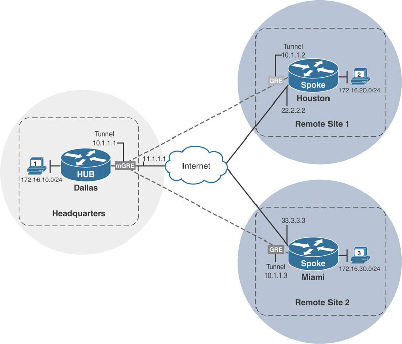
Earlier, we discussed the problem of providing WAN connectivity to allow branch sites of a corporation to communicate with each other. To create a scalable and dynamic WAN strategy, a DMVPN solution was implemented as an overlay network. This network used only a single tunnel interface on three routers to create a hub-and-spoke network. The hub router Dallas leverages mGRE and NHRP to dynamically create a tunnel between itself and the branch (spoke) office routers Houston and Miami, which both use traditional point-to-point GRE tunnels.
The resulting overall design mimics a traditional hub-and-spoke network, where all traffic between Miami and Houston first travels through Dallas. In this design, Miami and Houston cannot communicate directly with each other. This design implementation is referred to as DMVPN Phase 1.
DMVPN Phase 1 uses mGRE interfaces on the hub router and point-to-point GRE tunnel interfaces on the spoke routers. With point-to-point GRE interfaces on spoke routers, all traffic sent by spokes through the DMVPN overlay is forced through the hub router. In other words, traffic from a spoke to another spoke always traverses the hub. Because traffic is forced through the hub router, there is no reason for the spokes to retain specific routing information for networks behind other spoke routers. The routing tables on the spokes can be optimized to a single default route received from the hub router.
To prove this point, a traceroute is performed below on Houston to the network address 172.16.30.1 on Miami. This network is advertised via EIGRP by the hub router Dallas to Houston. As seen below, the path taken to reach this address is from Houston, then to Dallas, and then to Miami.
Houston#show ip route eigrp | begin Gateway

Gateway of last resort is not set

      172.16.0.0/16 is variably subnetted, 4 subnets, 2 masks
D        172.16.10.0/24 [90/27008000] via 10.1.1.1, 01:00:20, Tunnel1
D        172.16.30.0/24 [90/28288000] via 10.1.1.1, 01:00:19, Tunnel1

Houston#traceroute 172.16.30.1 source 172.16.20.1

Type escape sequence to abort.
Tracing the route to 172.16.30.1
VRF info: (vrf in name/id, vrf out name/id)
  1 10.1.1.1 0 msec 5 msec 5 msec
  2 10.1.1.3 1 msec 5 msec 5 msec
Since traffic from Houston’s LAN segment takes a Houston ➔ Dallas ➔ Miami path, the specific routing information for Miami’s connected LAN segment 172.16.30.0/24 is unnecessary in the routing table on Houston. Dallas could send a default route to both spokes and Houston would still take the same Houston ➔ Dallas ➔ Miami path as shown below:
Dallas#show run interface tunnel1 | begin int

interface Tunnel1
 ip address 10.1.1.1 255.255.255.0
 no ip redirects
 no ip split-horizon eigrp 1
 ip nhrp map multicast dynamic
 ip nhrp network-id 1
 ip nhrp redirect
 ip summary-address eigrp 1 0.0.0.0 0.0.0.0
 tunnel source 11.1.1.1
 tunnel mode gre multipoint
end

Houston#show ip route eigrp | begin Gateway
Gateway of last resort is 10.1.1.1 to network 0.0.0.0

D*    0.0.0.0/0 [90/27008000] via 10.1.1.1, 00:00:54, Tunnel1

Houston#traceroute 172.16.30.1 source 172.16.20.1

Type escape sequence to abort.
Tracing the route to 172.16.30.1
VRF info: (vrf in name/id, vrf out name/id)
  1 10.1.1.1 0 msec 5 msec 5 msec
  2 10.1.1.3 1 msec 5 msec 5 msec
Using the ip summary-address eigrp 1 command, Dallas has been instructed to advertise a default summary route out of its tunnel interface. This causes Dallas to suppress all specific routes and only send a single default route to the spokes Houston and Miami. As mentioned, the traffic path remains the same from Houston’s 172.16.20.0/24 LAN segment and Miami’s 172.16.30.0/24 LAN segment. What has changed is the routing tables on the spokes have been optimized by removing unnecessary specific routing information about remote spoke LAN segments that do not have an effect on the DMVPN traffic flow. Such an optimization is recommended whenever possible in a DMVPN implementation.
Dynamic Spoke-to-Spoke Tunnels
DMVPN Phase 1 is the simplest phase to implement. As long as the hub has enough resources to service the spokes, the network will perform well. Phase 1 also allows for complete reduction of routing information by sending a default route down to the spoke sites. This way, spoke routing tables can be kept efficient. However, Phase 1 optimizes the routing tables of spoke routers at the cost of routing efficiency between spokes. DMVPN Phases 2 and 3 introduce the concept of spoke-to-spoke tunnels.
The Need for Spoke-to-Spoke Tunnels
The goal for any DMVPN deployment is to provide connectivity between clients connected at remote sites of an organization. In our example, the clients located at the Miami and Houston sites need to be able to communicate not only with the Dallas site but with each other as well.
As the company grows and branch offices are added, those branch offices are also additional spokes in the DMVPN network. With more spokes, the amount of traffic increases across the DMVPN network. If the hub router is overloaded with traffic, overall network performance suffers. Through traffic analysis, network operators can determine whether the majority of the increased traffic is spoke-to-hub or spoke-to-spoke communication. If the majority is spoke-to-hub, the hub router resources may need to be increased. If it is spoke-to-spoke, however, the bottleneck can be relieved by simply allowing spoke sites to communicate with one another directly.
There are two main topologies for allowing spoke-to-spoke connectivity: full-mesh and partial-mesh. In full-mesh topologies, all routers have direct connections with each other, as shown here:
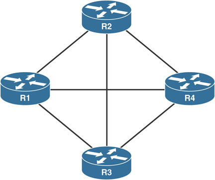
In the above, if R1 needed to reach any router, it can do so directly without using another router as transit. This design is also fault tolerant. If R1 loses its link to R2, it can route around the failure through R3.
The downside of full-mesh topologies is the cost of provisioning the circuits between sites. An alternative is to identify which sites contribute to the majority of direct traffic and directly connect those sites. Such a design, like the one shown here, would be considered to be a partial-mesh design:
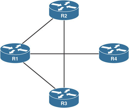
The sites that have direct connections are determined based on traffic patterns and volume at each individual site. The partially meshed sites exchange each other’s routing information and can route directly to each other, relieving tension at the hub site.
Partial-mesh solutions provide cost savings over full-mesh solutions, but they still carry costs related to provisioning additional WAN circuits. Also, a direct connection between spokes may only be needed in peak seasons. It might be difficult and costly to provision a direct WAN circuit between sites for seasonal traffic spikes; this is a downside with both partial- and full-mesh designs.
DMVPN addresses this problem by supporting dynamic spoke-to-spoke tunnels between DMVPN spokes. A dynamic spoke-to-spoke tunnel is a temporary tunnel that spoke sites build and use whenever the traffic flows require it. If the tunnel goes unused, it is torn down until it is needed again. Spoke-to-spoke tunnels were first introduced in DMVPN Phase 2.
In order to lift the Phase 1 requirement of spoke-hub-spoke traffic patterns, a DMVPN network needs to be modified in two ways:
Spokes need the ability to support multiple endpoints on the DMVPN tunnel interface.
Mechanisms that trigger direct communication between spokes are needed.
Enabling Multipoint GRE on Spokes
The first point highlights the major limiting factor of DMVPN Phase 1, which is the point-to-point GRE tunnel configuration on the spokes. With a hub configured as the sole endpoint for the DMVPN tunnel interface, there is no way for the spokes to even form a direct tunnel between each other. Thus, the point-to-point GRE tunnels on the spokes need to be traded out for mGRE tunnels, just like on the hub router. To provide this functionality, the tunnel interfaces on all routers are shut down. Then the tunnel destination command is removed, and tunnel mode gre multipoint is configured instead on the Houston and Miami routers. Finally, the tunnel interfaces are brought back up, starting with Dallas:
Note
The sequence of shutting down the tunnel interfaces of all routers, bringing up the hub tunnel interface first, and then bringing up the spokes is vital. If the spoke tunnel interfaces are brought up before the hub, the first registration request sent from the spokes might not be received by the hub, causing delay in bringing up the DMVPN. With the hub interface up first, it is ensured that the first registration request sent from the spokes is received by the hub immediately.
On Dallas, Houston, and Miami:
interface Tunnel1
 shutdown
 end
On Houston and Miami:
interface Tunnel1
 no tunnel destination
 tunnel mode gre multipoint
On Dallas:
interface Tunnel1
 no shut
On Houston and Miami:
interface Tunnel1
 no shut
Once the tunnel interfaces come back up on all routers, a ping is issued from Dallas to Houston to test the configuration:
Dallas#ping 10.1.1.2

Type escape sequence to abort.
Sending 5, 100-byte ICMP Echos to 10.1.1.2, timeout is 2 seconds:
.....
Success rate is 0 percent (0/5)
As shown above, the ping is unsuccessful. The show dmvpn command is issued to check the status of DMVPN spoke registration on the hub, Dallas:
Dallas#show dmvpn

Legend: Attrb --> S - Static, D - Dynamic, I - Incomplete
        N - NATed, L - Local, X - No Socket
        # Ent --> Number of NHRP entries with same NBMA peer
        NHS Status: E --> Expecting Replies, R --> Responding, W -->
Waiting
        UpDn Time --> Up or Down Time for a Tunnel
===================================================================
This output confirms that neither Houston nor Miami has registered with the hub, preventing the hub from learning their NBMA-to-overlay mapping information. The debug ip nhrp packet output on Houston sheds light on the underlying problem:
Houston#debug nhrp packet
NHRP activity debugging is on

 NHRP: Incompatible Destination NBMA (UNKNOWN) for 'Tunnel1'
 NHRP: NHS-DOWN: 10.1.1.1
The debugging messages prove that Houston is trying to register with Dallas but is unable to. The failure occurs because the NBMA address for 10.1.1.1 (Dallas) is unknown to Houston. Recall that in order to successfully tunnel DMVPN traffic across the underlay, the router needs to know what NBMA address to use for the destination of the GRE/IP packet sent across the underlay.
Earlier, Houston had a static point-to-point tunnel interface, where this information was explicitly configured with the tunnel destination command. Now, Houston has an mGRE tunnel interface that does not accept static tunnel destination commands.
Houston(config-if)#tunnel destination 11.1.1.1

Tunnel destination configuration failed on tunnel in mode multi-GRE/
IP configuring 11.1.1.1: tunnel destination cannot be configured under
existing mode
When the spoke is unable to register with the hub, the DMVPN network is broken, and communication cannot continue. The solution to this problem is to provide the spoke routers with a static NHRP mapping for the hub. When the ip nhrp map command is used to configure the static mapping for the hub, the spoke can properly register with the hub, and the DMVPN network functions as normal. This configuration should be added in the configuration template for future spokes. Below, Houston is configured with the static NHRP mapping for the hub’s NBMA address. After the tunnel is flapped on Houston, Dallas receives the mapping, and ping succeeds again:
On Houston:
interface tunnel 1
 ip nhrp map 10.1.1.1 11.1.1.1 ! Static IP to NBMA mapping of the hub
 exit

Houston#show dmvpn | begin Interface
Interface: Tunnel1, IPv4 NHRP Details
Type:Spoke, NHRP Peers:1,

 # Ent  Peer NBMA address Peer Tunnel Add State  UpDn Tm Attrb
 ----- --------------- --------------- ----- -------- -----
     1 11.1.1.1               10.1.1.1    UP 00:01:59     S

Houston(config)#interface tunnel1
Houston(config-if)#shut

%LINEPROTO-5-UPDOWN: Line protocol on Interface Tunnel1, changed state
to down
%LINK-5-CHANGED: Interface Tunnel1, changed state to administratively
down

Houston(config-if)#no shut

%LINEPROTO-5-UPDOWN: Line protocol on Interface Tunnel1, changed state
to up
On Dallas:
Dallas#show dmvpn | begin Interface

Interface: Tunnel1, IPv4 NHRP Details
Type:Hub, NHRP Peers:1,


 # Ent  Peer NBMA address Peer Tunnel Add State  UpDn Tm Attrb
 ----- --------------- --------------- ----- -------- -----
     1 22.2.2.2               10.1.1.2    UP 00:01:03     D

Dallas#ping 10.1.1.2
Type escape sequence to abort.
Sending 5, 100-byte ICMP Echos to 10.1.1.2, timeout is 2 seconds:
!!!!!
Success rate is 100 percent (5/5), round-trip min/avg/max = 1/4/5 ms
Everything appears to be functioning. However, after some time, the following is logged on Houston:
Houston:

%DUAL-5-NBRCHANGE: EIGRP-IPv4 1: Neighbor 10.1.1.1 (Tunnel1) is down:
retry limit exceeded

%DUAL-5-NBRCHANGE: EIGRP-IPv4 1: Neighbor 10.1.1.1 (Tunnel1) is up:
new adjacency
The EIGRP neighborship to Dallas is flapping. This is the same situation experienced by Dallas regarding its mGRE interface. EIGRP uses multicast for hellos. Earlier, Houston had a point-to-point GRE tunnel and sent multicast EIGRP hello packets to Dallas. Dallas would create a neighbor structure and attempt to bring up the neighborship. Houston ignored Dallas’s unicast response because it had not yet seen a multicast hello from Dallas. The neighborship timed out, and the process repeated until Dallas was configured to dynamically populate its NHRP multicast table with NBMA destinations for all spokes that successfully register with it.
In this situation, Dallas is able to send multicast hellos to Houston, but Houston cannot send them to Dallas because the point-to-point tunnel has been converted into an mGRE interface. Like Dallas, Houston also needs a multicast mapping in its NHRP table for Dallas’s NBMA address to send multicasts successfully. The NHRP multicast tables on the routers confirm the problem:
On Dallas:
Dallas#show ip nhrp multicast

  I/F     NBMA address
Tunnel1    22.2.2.2        Flags: dynamic          (Enabled)
On Houston:
Houston#show ip nhrp multicast
  I/F     NBMA address
The solution for Dallas was to enable dynamic multicast mappings by using the ip nhrp map multicast dynamic command. Whenever a spoke registers, a multicast mapping is created. This works for DMVPN hub routers but does not work for DMVPN spoke routers. The DMVPN hub will never register its address with a DMVPN spoke router, rendering the ip nhrp map multicast dynamic command purposeless. Instead, a static multicast mapping should be enabled on the spoke, using the ip nhrp map multicast [IP address]. The IP address should be the NBMA address of the hub, as shown here:
On Houston:
interface Tunnel1
 ip nhrp map multicast 11.1.1.1 ! Static NHRP multicast mapping
Following this configuration, the EIGRP neighborship is established between Dallas and Houston, as shown below:
Houston:
%DUAL-5-NBRCHANGE: EIGRP-IPv4 1: Neighbor 10.1.1.1 (Tunnel1) is up:
new adjacency

Houston#show ip eigrp neighbors

EIGRP-IPv4 Neighbors for AS(1)
H   Address               Interface         Hold Uptime   SRTT   RTO  Q  Seq
                                            (sec)         (ms)       Cnt Num
0   10.1.1.1              Tu1                      13 00:00:44    5  1470  0  40
The following is a summary of static tunnel configurations that should be included in a template for configuring additional DMVPN spoke routers to enable proper DMVPN functionality:
On Spokes:
interface Tunnel1
 ip nhrp map 10.1.1.1 11.1.1.1
 ip nhrp map multicast 11.1.1.1
 ip nhrp network-id 1
 ip nhrp nhs 10.1.1.1
The total NHRP configuration takes five configuration commands, three of which are related to the NHS/NHC relationship.
As DMVPN matured, its designers came up with a collapsed command that reflects the same style of configuration but in a single line: ip nhrp nhs overlay-address nbma nbma-address multicast. This command configures the NHS, maps the NHS overlay address to the NBMA address, and also creates the required multicast mapping for the NHS. By using this command, the above configuration template can be condensed to:
On Spokes:
interface Tunnel1
 ip nhrp network-id 1
 ip nhrp nhs 10.1.1.1 nbma 11.1.1.1 multicast
end
The same command is then configured on Miami’s tunnel interface to complete its conversion to mGRE tunnels:
Miami:
interface Tunnel1
 ip address 10.1.1.3 255.255.255.0
 ip nhrp network-id 1
 ip nhrp nhs 10.1.1.1 nbma 11.1.1.1 multicast
 tunnel source 33.3.3.3
 tunnel mode gre multipoint
end
The output below verifies the DMVPN, EIGRP, and IP connectivity between Dallas and Miami and between the networks behind Houston and Miami:
On Dallas:
Dallas#show dmvpn | begin Interface

Interface: Tunnel1, IPv4 NHRP Details
Type:Hub, NHRP Peers:2,

 # Ent  Peer NBMA address Peer Tunnel Add State  UpDn Tm Attrb
 ----- --------------- --------------- ----- -------- -----
     1 22.2.2.2               10.1.1.2    UP 00:29:18     D
     1 33.3.3.3               10.1.1.3    UP 00:02:06     D


Dallas#show ip eigrp neighbors
EIGRP-IPv4 Neighbors for AS(1)

H   Address           Interface           Hold Uptime   SRTT   RTO  Q  Seq
                                           (sec)         (ms)       Cnt
Num
1   10.1.1.3          Tu1                   14 00:02:06    6  1512  0  25
0   10.1.1.2          Tu1                   14 00:12:44   25  1470  0  34

Dallas#ping 10.1.1.3

Type escape sequence to abort.
Sending 5, 100-byte ICMP Echos to 10.1.1.3, timeout is 2 seconds:
!!!!!
Success rate is 100 percent (5/5), round-trip min/avg/max = 1/4/5 ms
On Houston:
Houston#ping 172.16.30.1 source 172.16.20.1

Type escape sequence to abort.
Sending 5, 100-byte ICMP Echos to 172.16.30.1, timeout is 2 seconds:
Packet sent with a source address of 172.16.20.1
!!!!!
Success rate is 100 percent (5/5), round-trip min/avg/max = 1/3/5 ms
Forming Spoke-to-Spoke Tunnels
The spokes are ready to begin forming dynamic spoke-to-spoke tunnels using their mGRE interfaces. There is only one piece of information missing. In order to successfully build a tunnel over the DMVPN network, the spokes require the NBMA address of the destination DMVPN endpoint. This NBMA address is used in the outer GRE/IP header of the packet that is forwarded over the underlay.
Hubs gain this information about the spokes through the NHRP registration process outlined earlier. Spokes, on the other hand, do not register with each other. Upon initialization, a DMVPN spoke has no knowledge of other DMVPN spokes participating in its own DMVPN cloud. Spokes could be statically configured with additional NHRP mapping commands for each neighboring spoke. However, as spokes are added, keeping track of which spokes have static mappings and which spokes do not can become cumbersome. Also, static configurations of this kind remove the dynamic nature of DMVPN. The creators of DMVPN solved this problem by leveraging a relationship each spoke already has: the one with the hub itself.
Since the hub router receives all mapping information for all spokes connected to the DMVPN, spokes can ask the hub for the proper mapping using a process known as NHRP resolution. Through NHRP resolution, a spoke queries the hub for the proper NBMA-to-overlay mapping for a corresponding spoke router by sending an NHRP resolution request. With the addition of this relationship, the hub fulfills its full role as an NHS, providing a database of mappings for the spokes that require mapping information for other spokes connected to the DMVPN.
The resolution request sent by the spokes contains the source NBMA address of the spoke initiating the resolution request and the target overlay address for which an NBMA address mapping is needed.
This process can be seen when PC-2 behind Houston pings PC-3 behind Miami for the first time. The target in this case is 10.1.1.3 (indicated in the dst protocol field in the output), and the source is Houston’s own NBMA 22.2.2.2:
PC-2#ping 172.16.30.2

Type escape sequence to abort.
Sending 5, 100-byte ICMP Echos to 172.16.30.2, timeout is 2 seconds:
.!!!!
Success rate is 80 percent (4/5), round-trip min/avg/max = 1/4/5 ms
Houston:
 NHRP: Send Resolution Request via Tunnel1 vrf 0, packet size: 72
  src: 10.1.1.2, dst: 10.1.1.3
  (F) afn: AF_IP(1), type: IP(800), hop: 255, ver: 1

      shtl: 4(NSAP), sstl: 0(NSAP)
      pktsz: 72 extoff: 52
(M) flags: "router auth src-stable nat ", reqid: 10
      src NBMA: 22.2.2.2
      src protocol: 10.1.1.2, dst protocol: 10.1.1.3
  (C-1) code: no error(0)
        prefix: 32, mtu: 17916, hd_time: 7200
        addr_len: 0(NSAP), subaddr_len: 0(NSAP), proto_len: 0, pref: 0
Houston begins by sending a NHRP resolution request to Dallas. Dallas receives the resolution request and forwards the packet out its tunnel interface toward Miami. The hub makes this decision based on the destination protocol address, which in this case is 10.1.1.3:
Dallas:
--Certain debug outputs have been omitted for brevity--

NHRP: Receive Resolution Request via Tunnel1 vrf 0, packet size: 72

      src NBMA: 22.2.2.2
      src protocol: 10.1.1.2, dst protocol: 10.1.1.3

 NHRP: Forwarding Resolution Request via Tunnel1 vrf 0, packet size:
92
  src: 10.1.1.1, dst: 10.1.1.3
      src NBMA: 22.2.2.2
      src protocol: 10.1.1.2, dst protocol: 10.1.1.3
Miami receives the resolution request, which contains the NBMA address of Houston. Using this address, Miami sends a resolution reply directly to Houston:
Miami:
--Certain debug outputs have been omitted for brevity--

NHRP: Receive Resolution Request via Tunnel1 vrf 0, packet size: 92

      src NBMA: 22.2.2.2
      src protocol: 10.1.1.2, dst protocol: 10.1.1.3


 NHRP: Send Resolution Reply via Tunnel1 vrf 0, packet size: 120
  src: 10.1.1.3, dst: 10.1.1.2

      src NBMA: 22.2.2.2
      src protocol: 10.1.1.2, dst protocol: 10.1.1.3

        client NBMA: 33.3.3.3
        client protocol: 10.1.1.3
The resolution reply contains Miami’s NHRP client information (highlighted in blue above). Once Houston receives this information, it adds it to its NHRP mapping table. Houston now has all the information needed to send messages directly to Miami without traversing the hub, leading to the formation of a spoke-to-spoke tunnel:
Houston:
NHRP: Receive Resolution Reply via Tunnel1 vrf 0, packet size: 120
  (F) afn: AF_IP(1), type: IP(800), hop: 255, ver: 1
      shtl: 4(NSAP), sstl: 0(NSAP)
      pktsz: 120 extoff: 60
  (M) flags: "router auth dst-stable unique src-stable nat ", reqid:
10
      src NBMA: 22.2.2.2
      src protocol: 10.1.1.2, dst protocol: 10.1.1.3
  (C-1) code: no error(0)
        prefix: 32, mtu: 17916, hd_time: 7200
        addr_len: 4(NSAP), subaddr_len: 0(NSAP), proto_len: 4, pref: 0
        client NBMA: 33.3.3.3
        client protocol: 10.1.1.3
The show ip nhrp command output below shows the contents of the NHRP mapping table on Houston. Notice that it now includes dynamic mapping information for Miami’s tunnel interface 10.1.1.3 to the NBMA address 33.3.3.3:
Houston#show ip nhrp

10.1.1.1/32 via 10.1.1.1
   Tunnel1 created 00:15:21, never expire
   Type: static, Flags: used
   NBMA address: 11.1.1.1

10.1.1.2/32 via 10.1.1.2
   Tunnel1 created 00:13:57, expire 01:46:02
   Type: dynamic, Flags: router unique local
   NBMA address: 22.2.2.2
    (no-socket)
10.1.1.3/32 via 10.1.1.3
   Tunnel1 created 00:13:57, expire 01:46:02
   Type: dynamic, Flags: router nhop
   NBMA address: 33.3.3.3
Finally, a traceroute between the two PCs confirms direct connectivity:
PC-2#traceroute 172.16.30.2

Type escape sequence to abort.
Tracing the route to 172.16.30.2
VRF info: (vrf in name/id, vrf out name/id)
  1 172.16.20.1 1 msec 0 msec 6 msec ! Houston
  2 10.1.1.3 6 msec 6 msec 1 msec    ! Miami
  3 172.16.30.2 1 msec 1 msec 0 msec
This is the general process used for building the NHRP mapping information between two spokes. Keep in mind that the Miami router performs the same steps when routing the return traffic back to Houston: It sends a resolution request to Dallas, Dallas forwards to Houston, Houston replies directly to Miami, and Miami adds the mapping information for Houston.
Note
In earlier implementations of DMVPN, the hub router would respond directly to the spoke sending the resolution request with the proper mapping information. This functionality has been modified in recent IOS versions to provide more scalability and support for hierarchical hub routers in advanced DMVPN designs. Furthermore, allowing the target spoke to respond directly to the requesting spoke ensures that the most up-to-date mapping information is gained in an efficient way in the event that changes are made in other areas of the DMVPN hierarchy.
Triggering NHRP Resolutions
The NHRP resolution process provides an elegant solution for spokes to learn the required mapping information for creating dynamic spoke-to-spoke tunnels. But how does a spoke know to perform such a function? DMVPN Phases 2 and 3 accomplish this feat in two different ways, which will be explored later.
Phase 2: Spoke-Initiated Spoke-to-Spoke Tunnels
Spoke-to-spoke tunnels were first introduced in DMVPN Phase 2 as an enhancement to the hub-and-spoke model of DMVPN Phase 1. In Phase 2, the responsibility for knowing when to send NHRP resolution requests was given to each spoke individually, meaning spokes actually initiated the NHRP resolution process when they determined that a packet needed a spoke-to-spoke tunnel.
The spoke would make this decision based on the information contained in its own routing table with the help of Cisco Express Forwarding (CEF). The routing table on Houston provides insight into how this trigger works:
Houston#show ip route eigrp | begin Gateway
Gateway of last resort is not set

      172.16.0.0/16 is variably subnetted, 4 subnets, 2 masks
D        172.16.10.0/24 [90/27008000] via 10.1.1.1, 00:20:52, Tunnel1
D        172.16.30.0/24 [90/28185600] via 10.1.1.3, 00:20:36, Tunnel1
Notice the second entry in Houston’s routing table for 172.16.30.0/24, the Miami LAN. Houston has received the route for that prefix on its Tunnel1 interface, pointing to Miami’s overlay address 10.1.1.3 as the next hop. In normal IP routing forwarding, when Houston sends traffic destined to that LAN out the tunnel interface, it performs the following:
Houston sends the packet to the tunnel interface.
The tunnel interface forces encapsulation of a new GRE/IP header. The source and destination are determined by the tunnel source and tunnel destination configurations made under the tunnel interface.
The new GRE/IP packet is routed based on the new destination IP address contained in the outer GRE/IP header. Layer 2 forwarding information is added as well.
The new packet is forwarded out an exit interface.
This process applies to normal point-to-point tunnel interfaces. Houston, however, does not have a point-to-point tunnel interface anymore, and it doesn’t have sufficient forwarding information to build the outer GRE/IP header. Here is where the CEF table comes in.
CEF precomputes rewrite headers in an adjacency table, which contains next hop forwarding information for directly connected devices. The basic process is as follows: Routing table entries are downloaded into the CEF Forwarding Information Base (FIB). At the same time, CEF completes the recursive process in the routing table to determine the appropriate exit interfaces for all routes contained in the routing table. Then, CEF determines whether adjacency information is available for the next hop/exit interface pairs. These are recorded in the adjacency table linked to the corresponding FIB entry by a key.
The show ip cef internal command shows this information. Let’s compare the show ip cef internal output on Houston for Dallas’s overlay address to the 172.16.30.2 (PC-3) address behind Miami:
Houston#show ip cef 10.1.1.1 internal

10.1.1.1/32, epoch 0, flags attached, refcount 5, per-destination
sharing
  sources: Adj
  subblocks:
   Adj source: IP midchain out of Tunnel1, address 10.1.1.1 F2776928
    Dependent covered prefix type adjfib, cover 10.1.1.0/24
  ifnums:
   Tunnel1(23): 10.1.1.1
  path F2765DF8, path list F2798F84, share 1/1, type adjacency
prefix, for IPv4
  attached to Tunnel1, adjacency IP midchain out of Tunnel1, address
10.1.1.1 F2776928
  output chain: IP midchain out of Tunnel1, address 10.1.1.1 F2776928
IP adj out of Ethernet0/0, address 22.2.2.1 F4EDE6A8

Houston#show ip cef 172.16.30.2 internal

172.16.30.0/24, epoch 0, RIB[I], refcount 5, per-destination sharing
  sources: RIB
  feature space:
   IPRM: 0x00028000
  ifnums:
   Tunnel1(23): 10.1.1.3
  path F527E768, path list F527F924, share 1/1, type attached nexthop,
for IPv4
  nexthop 10.1.1.3 Tunnel1, adjacency IP midchain out of Tunnel1,
address 10.1.1.3 (incomplete)
  output chain: IP midchain out of Tunnel1, address 10.1.1.3
(incomplete) drop
The portions highlighted in red reveal a major difference. Houston has calculated the next hop as 10.1.1.1 for Dallas’s overlay address. It has also calculated the next hop as 10.1.1.3 for PC-3 (based on the IP routing table) at the Miami site. The difference lies in the adjacency information.
For Dallas’s overlay address, the FIB output shows an adjacency as attached, while the adjacency for PC-3 shows as incomplete. The show adjacency and show adjacency encapsulation commands can be used to gain a little more insight into this:
Houston#show adjacency

Protocol Interface                 Address
IP       Ethernet0/0               22.2.2.1(18)
IP       Ethernet0/1               172.16.20.2(7)
IP       Tunnel1                   10.1.1.1(11)
IP       Tunnel1                   10.1.1.3(5) (incomplete)

Houston#show adjacency encapsulation | begin 10.1.1.1

IP       Tunnel1                   10.1.1.1(11)
  Encap length 24
  4500000000000000FF2F97C916020202
  0B01010100000800
  Provider: TUNNEL
  Protocol header count in macstring: 2
    HDR 0: ipv4
       dst: static, 11.1.1.1
       src: static, 22.2.2.2
      prot: static, 47
       ttl: static, 255
        df: static, cleared
      per packet fields: tos ident tl chksm
    HDR 1: gre
      prot: static, 0x800
      per packet fields: none
IP       Tunnel1                   10.1.1.3(5) (incomplete)
  adjacency is incomplete
This disparity has important ramifications for how Houston will route the packet. In the case of Dallas’s overlay address, the adjacency table shows it has completed precalculated forwarding information for its next hop. For Miami’s LAN, this information is incomplete. This incomplete entry in Houston’s adjacency table triggers Houston to send an NHRP resolution request in order to gain the information it needs to form a spoke-to-spoke tunnel. In this case, Houston requires Miami’s NBMA address.
The process goes as follows:
Houston receives a packet destined for PC-3 from PC-2.
Houston checks its FIB for precalculated routing information.
The FIB points to incomplete adjacency information.
Houston sends an NHRP resolution request to the hub in response to the incomplete adjacency.
Houston has a decision to make:
Drop the packet.
Delay forwarding the packet until the NHRP resolution process completes.
Forward the traffic along a known good path.
The NHRP resolution process completes, the adjacency is properly populated, and Houston has a spoke-to-spoke tunnel with Miami.
Subsequent packets are forwarded directly to Miami through the spoke-to-spoke tunnel.
The key part of this process is that once Houston determines it needs more forwarding information to forward the packet to PC-3 at step 5, there are a number of actions it can take. The designers of DMVPN chose to go with the third option, where, in this case, Houston forwards the packets along a known good path. With this default behavior, rather than simply dropping or delaying the packet, Houston chooses to forward it in a direction where there is a high likelihood of its reaching the proper destination. This direction is toward the hub or, more specifically, the NHRP NHS.
The reasoning behind this behavior is that if Houston is relying on the hub to provide the mapping information, the hub must have the mapping information itself and can forward the packet accordingly. Doing so ensures that traffic to PC-3 routed through Houston still reaches PC-3 while Houston works out the spoke-to-spoke tunnel formation. The result is that the first packet Houston sends that requires a spoke-to-spoke tunnel will always traverse the hub until the spoke-to-spoke tunnel is formed. Subsequent packets will not traverse the hub.
The debug output below shows the NHRP resolution process. Dallas receives the resolution request from Houston. It forwards the request to Miami. Miami receives the resolution request, and sends a resolution reply packet, containing its NBMA to Overlay mapping information, and back to Houston directly (note the source and destination IP addresses in the reply debug). Houston will receive this reply from Miami and add an entry in its NHRP mapping table for Miami’s NBMA address.
On Dallas:
 NHRP: Receive Resolution Request via Tunnel1 vrf 0, packet size: 72
  (F) afn: AF_IP(1), type: IP(800), hop: 255, ver: 1
      shtl: 4(NSAP), sstl: 0(NSAP)
      pktsz: 72 extoff: 52
  (M) flags: "router auth src-stable nat ", reqid: 6

 NHRP: Forwarding Resolution Request via Tunnel1 vrf 0, packet size:
92
  src: 10.1.1.1, dst: 172.16.30.2
  (F) afn: AF_IP(1), type: IP(800), hop: 254, ver: 1
      shtl: 4(NSAP), sstl: 0(NSAP)
      pktsz: 92 extoff: 52
  (M) flags: "router auth src-stable nat ", reqid: 6
On Miami:
 NHRP: Receive Resolution Request via Tunnel1 vrf 0, packet size: 92
  (F) afn: AF_IP(1), type: IP(800), hop: 254, ver: 1
      shtl: 4(NSAP), sstl: 0(NSAP)
      pktsz: 92 extoff: 52
  (M) flags: "router auth src-stable nat ", reqid: 6

 NHRP: Send Resolution Reply via Tunnel1 vrf 0, packet size: 120
  src: 10.1.1.3, dst: 10.1.1.2
  (F) afn: AF_IP(1), type: IP(800), hop: 255, ver: 1
      shtl: 4(NSAP), sstl: 0(NSAP)
      pktsz: 120 extoff: 60
  (M) flags: "router auth dst-stable unique src-stable nat ", reqid: 6
      src NBMA: 22.2.2.2
      src protocol: 10.1.1.2, dst protocol: 172.16.30.2
  (C-1) code: no error(0)
        prefix: 24, mtu: 17916, hd_time: 7200
        addr_len: 4(NSAP), subaddr_len: 0(NSAP), proto_len: 4, pref: 0
        client NBMA: 33.3.3.3
        client protocol: 10.1.1.3
On Houston:
Houston#show ip nhrp

10.1.1.1/32 via 10.1.1.1
  Tunnel1 created 00:35:34, never expire
   Type: static, Flags: used
   NBMA address: 11.1.1.1
--- omitted ---
172.16.30.0/24 via 10.1.1.3
   Tunnel1 created 00:11:18, expire 01:48:41
   Type: dynamic, Flags: router rib
   NBMA address: 33.3.3.3
Phase 2 Spoke-to-Spoke Tunnel Caveats
You have seen the basic spoke-to-spoke tunnel formation process in DMVPN Phase 2, and you now need to see the mechanisms that make it possible:
Spokes are configured with mGRE interfaces.
A routing table is populated with specific prefixes for remote spoke LANs.
The next hop for those prefixes points to the specific remote spoke’s tunnel IP address.
It is important to realize that all three of these points must be met in order for spoke-to-spoke tunnels to form in DMVPN Phase 2. If any of them is missing, spoke-to-spoke tunnels cannot form. Let’s look first at a scenario where the spoke doesn’t have an mGRE tunnel but all other points are fulfilled. Say that Houston and Miami have been configured with a standard point-to-point tunnel to the hub and all other configurations have been kept the same on the other routers. The following is Houston’s resulting routing table:
Houston#show ip route eigrp | begin Gateway
Gateway of last resort is not set

      172.16.0.0/16 is variably subnetted, 4 subnets, 2 masks
D        172.16.10.0/24 [90/27008000] via 10.1.1.1, 00:00:12, Tunnel1
D        172.16.30.0/24 [90/28185600] via 10.1.1.3, 00:00:12, Tunnel1
No matter how many times a traceroute between the PCs is formed, traffic always goes through the hub (highlighted in red):
PC-2#traceroute 172.16.30.2

Type escape sequence to abort.
Tracing the route to 172.16.30.2
VRF info: (vrf in name/id, vrf out name/id)
  1 172.16.20.1 0 msec 5 msec 5 msec
  2 10.1.1.1 0 msec 5 msec 5 msec
  3 10.1.1.3 1 msec 5 msec 5 msec
  4 172.16.30.2 5 msec 0 msec 5 msec

PC-2#traceroute 172.16.30.2

Type escape sequence to abort.
Tracing the route to 172.16.30.2
VRF info: (vrf in name/id, vrf out name/id)
  1 172.16.20.1 0 msec 5 msec 5 msec
  2 10.1.1.1 5 msec 5 msec 5 msec
  3 10.1.1.3 5 msec 1 msec 5 msec
  4 172.16.30.2 1 msec 0 msec 5 msec

PC-2#traceroute 172.16.30.2

Type escape sequence to abort.
Tracing the route to 172.16.30.2
VRF info: (vrf in name/id, vrf out name/id)
  1 172.16.20.1 5 msec 5 msec 5 msec
  2 10.1.1.1 5 msec 0 msec 5 msec
  3 10.1.1.3 0 msec 1 msec 0 msec
  4 172.16.30.2 1 msec 1 msec 0 msec
The reason for this lies in the CEF adjacency table for the tunnel interface, shown below on Houston:
Houston#show ip cef 172.16.30.2 internal

172.16.30.0/24, epoch 0, RIB[I], refcount 5, per-destination sharing
  sources: RIB
  feature space:
   IPRM: 0x00028000

  ifnums:
   Tunnel1(23)
  path F527CE50, path list F42B873C, share 1/1, type attached nexthop,
for IPv4
  nexthop 10.1.1.3 Tunnel1, adjacency IP midchain out of Tunnel1
F27757F8
  output chain: IP midchain out of Tunnel1 F27757F8 IP adj out of
Ethernet0/0, address 22.2.2.1 F4EDE6A8

Houston#show adjacency tunnel1

Protocol Interface                 Address
IP       Tunnel1                   point2point(14)

Houston#show adjacency encapsulation | begin Tunnel1

IP       Tunnel1                   point2point(14)
  Encap length 24
  4500000000000000FF2F97C916020202
  0B01010100000800
  Provider: TUNNEL
  Protocol header count in macstring: 2
    HDR 0: ipv4
       dst: static, 11.1.1.1
       src: static, 22.2.2.2
      prot: static, 47
       ttl: static, 255
        df: static, cleared
      per packet fields: tos ident tl chksm
    HDR 1: gre
      prot: static, 0x800
      per packet fields: none
Notice that the adjacency for all prefixes out the tunnel interface points to a point2point adjacency. The point2point adjacency artificially fills in the NBMA address for Dallas as the outer header of the GRE/IP packet. With this configuration, there is no way for Houston to form a spoke-to-spoke tunnel because traffic routed out the tunnel will always go to Dallas, based on these CEF entries. This is why mGRE interfaces are required for spoke-to-spoke tunnels in DMVPN.
To prove the second requirement’s importance, Houston and Miami are configured with mGRE interfaces again, but the routing protocol configuration on Dallas has been modified such that only a default route is sent to the spokes. The resulting routing table on Houston is as follows:
Houston#show ip route eigrp | begin Gateway
Gateway of last resort is 10.1.1.1 to network 0.0.0.0

D*    0.0.0.0/0 [90/27008000] via 10.1.1.1, 00:00:15, Tunnel1
Again, each traceroute proves that the hub is still being used at every point to transit traffic:
PC-2#traceroute 172.16.30.2

Type escape sequence to abort.
Tracing the route to 172.16.30.2
VRF info: (vrf in name/id, vrf out name/id)
  1 172.16.20.1 5 msec 5 msec 0 msec
  2 10.1.1.1 0 msec 5 msec 0 msec
  3 10.1.1.3 1 msec 3 msec 5 msec
  4 172.16.30.2 1 msec 0 msec 1 msec

PC-2#traceroute 172.16.30.2

Type escape sequence to abort.
Tracing the route to 172.16.30.2
VRF info: (vrf in name/id, vrf out name/id)
  1 172.16.20.1 6 msec 5 msec 5 msec
  2 10.1.1.1 5 msec 5 msec 5 msec
  3 10.1.1.3 0 msec 6 msec 5 msec
  4 172.16.30.2 0 msec 6 msec 2 msec

PC-2#traceroute 172.16.30.2

Type escape sequence to abort.
Tracing the route to 172.16.30.2
VRF info: (vrf in name/id, vrf out name/id)
  1 172.16.20.1 5 msec 4 msec 1 msec
  2 10.1.1.1 0 msec 6 msec 4 msec
  3 10.1.1.3 5 msec 5 msec 5 msec
  4 172.16.30.2 6 msec 4 msec 5 msec
The reason again is that the CEF adjacency entry for the default route points to Dallas as the next hop, which is not an incomplete entry. As a result, Houston sends traffic directly to the hub even though a better path can be established directly with Miami. This point highlights the fact that the CEF incomplete entry is what triggers the spoke-to-spoke tunnel formation in DMVPN Phase 2:
Houston#show ip cef 172.16.30.2 internal

0.0.0.0/0, epoch 0, flags default route, RIB[I], refcount 5,
per-destination sharing
  sources: RIB, DRH
  feature space:
   IPRM: 0x00028000
  ifnums:
   Tunnel1(23): 10.1.1.1
  path F42B8818, path list F42B99B4, share 1/1, type attached nexthop,
for IPv4
  nexthop 10.1.1.1 Tunnel1, adjacency IP midchain out of Tunnel1,
address 10.1.1.1 F27757F8
  output chain: IP midchain out of Tunnel1, address 10.1.1.1 F27757F8
IP adj out of Ethernet0/0, address 22.2.2.1 F4EDE6A8

Houston#show adjacency tunnel1

Protocol Interface                 Address
IP       Tunnel1                   10.1.1.1(11)

Houston#show adjacency tunnel1 encapsulation

Protocol Interface                 Address
IP       Tunnel1                   10.1.1.1(11)
  Encap length 24
  4500000000000000FF2F97C916020202
  0B01010100000800
  Provider: TUNNEL
  Protocol header count in macstring: 2
    HDR 0: ipv4
       dst: static, 11.1.1.1
       src: static, 22.2.2.2
      prot: static, 47
       ttl: static, 255
        df: static, cleared

 per packet fields: tos ident tl chksm
    HDR 1: gre
      prot: static, 0x800
      per packet fields: none
The final case outlines that the above is not the only requirement. Even with specific prefixes and mGRE interfaces, if the next hops do not point to the proper remote spokes, no spoke-to-spoke tunnel will be formed. To demonstrate, the routing protocol on Dallas has been configured to set Dallas itself as the next hop for all prefixes it advertises to the spokes. The resulting routing table on Houston is as follows:
Houston#show ip route eigrp | begin Gateway
Gateway of last resort is not set

      172.16.0.0/16 is variably subnetted, 4 subnets, 2 masks
D        172.16.10.0/24 [90/27008000] via 10.1.1.1, 00:00:12, Tunnel1
D        172.16.30.0/24 [90/28185600] via 10.1.1.1, 00:00:12, Tunnel1
Again, traceroutes from PC-2 to PC-3 all traverse the hub.
PC-2#traceroute 172.16.30.2

Type escape sequence to abort.
Tracing the route to 172.16.30.2
VRF info: (vrf in name/id, vrf out name/id)
  1 172.16.20.1 0 msec 6 msec 5 msec
  2 10.1.1.1 0 msec 5 msec 5 msec
  3 10.1.1.3 0 msec 6 msec 5 msec
  4 172.16.30.2 1 msec 0 msec 6 msec

PC-2#traceroute 172.16.30.2

Type escape sequence to abort.
Tracing the route to 172.16.30.2
VRF info: (vrf in name/id, vrf out name/id)
  1 172.16.20.1 5 msec 5 msec 5 msec

  2 10.1.1.1 1 msec 5 msec 5 msec
  3 10.1.1.3 0 msec 5 msec 5 msec
  4 172.16.30.2 1 msec 5 msec 5 msec

PC-2#traceroute 172.16.30.2

Type escape sequence to abort.
Tracing the route to 172.16.30.2
VRF info: (vrf in name/id, vrf out name/id)
  1 172.16.20.1 5 msec 5 msec 5 msec
  2 10.1.1.1 1 msec 5 msec 5 msec
  3 10.1.1.3 1 msec 5 msec 5 msec
  4 172.16.30.2 1 msec 1 msec 0 msec
Investigating the CEF tables for the destination reveals that the next hop being set to the hub forces Houston to use the hub’s adjacency information for forwarding. The CEF entries do not lead to incomplete adjacencies, and spoke-to-spoke tunnels do not form:
Houston#show ip cef 172.16.30.2 internal

172.16.30.0/24, epoch 0, RIB[I], refcount 5, per-destination sharing
  sources: RIB
  feature space:
   IPRM: 0x00028000
  ifnums:
   Tunnel1(23): 10.1.1.1
  path F42B87A8, path list F42B99B4, share 1/1, type attached nexthop,
for IPv4
  nexthop 10.1.1.1 Tunnel1, adjacency IP midchain out of Tunnel1,
address 10.1.1.1 F27757F8
  output chain: IP midchain out of Tunnel1, address 10.1.1.1 F27757F8
IP adj out of Ethernet0/0, address 22.2.2.1 F4EDE6A8

Houston#show adjacency tunnel1

Protocol Interface                 Address
IP       Tunnel1                   10.1.1.1(12)

Houston#show adjacency tunnel1 encapsulation

Protocol Interface                 Address
IP       Tunnel1                   10.1.1.1(12)

  Encap length 24
  4500000000000000FF2F97C916020202
  0B01010100000800
  Provider: TUNNEL
  Protocol header count in macstring: 2
    HDR 0: ipv4
       dst: static, 11.1.1.1
       src: static, 22.2.2.2
      prot: static, 47
       ttl: static, 255
        df: static, cleared
      per packet fields: tos ident tl chksm
    HDR 1: gre
      prot: static, 0x800
      per packet fields: none
The results of these requirements carry heavy ramifications on DMVPN Phase 2’s spoke-to-spoke mechanics. Specifically, the requirement where the spokes need to have complete routing information for all networks behind remote spokes eliminates the routing table efficiencies gained in DMVPN Phase 1. No longer can the hub send a simple default route down to the spokes. Thus, routing table optimization is traded in favor of data plane optimization.
DMVPN Phase 2 requires mGRE interfaces and specific routes for all spoke networks, and each of those routes should point to the owning spoke. All of this needs to exist in the spoke routing table in order to trigger spoke-to-spoke tunnels. These requirements severely limit the scalability of DMVPN as the number of spoke sites grows. The limiting factor then becomes a combination of the memory on each spoke router dedicated to storing additional routes and CEF entries and the routing protocol processing overhead on the hub router. Luckily, there is an optimization for that: DMVPN Phase 3.
Phase 3: Hub-Initiated Spoke-to-Spoke Tunnels
DMVPN Phase 3 was engineered to solve the deficiencies of Phase 2. Phase 2 requires specific prefixes on each spoke router in order to properly trigger NHRP resolution for spoke-to-spoke tunnels. With such a configuration, spoke routing tables may contain routes to prefixes the spoke may never use but that they must have just in case a spoke-to-spoke tunnel needs to be formed. Phase 2 also eliminates summarization from the hub to the spokes, although summarization can still be performed from the spokes to the hub. Without summarization from hub to spoke, the routing protocol overhead on the hub itself increases based on the number of routes each spoke advertises to it.
DMVPN Phase 3 takes a different approach to triggering spoke-to-spoke tunnels. Rather than having the spokes make the determination, Phase 3 DMVPN shifts this responsibility to the hub router. The logic here is that because the first packet is always routed to the hub in the first place, why not have the hub signal the NHRP resolution process itself?
Note
There is no official documentation to support the logic presented above. The lab authors assume this conversation was had at some point by Cisco developers.
This feature was introduced with the NHRP shortcut switching enhancements. The basic idea is that, by using NHRP messaging, the hub can signal to the spokes whenever the potential for a spoke-to-spoke tunnel exists for specific networks. After the spokes complete the resolution process for a remote spoke, NHRP running on the spoke amends the routing table with special NHRP shortcut or override routes. These routes lead to the proper CEF entries required to force the spoke to continue to use the established spoke-to-spoke tunnel for subsequent packets sent to that specific network.
Whenever the hub forwards a packet out of the same DMVPN tunnel interface the packet was received on (an indication of a hair pinning the traffic), it sends what is known as an NHRP traffic indication message. This process mimics the logic used by the router when it transits traffic it receives on an Ethernet interface out the same Ethernet interface. The difference is that it sends an ICMP redirect message instead.
The NHRP traffic indication message is sent out the hub’s tunnel interface toward the source of the hairpinned packet, which ends up at the originating spoke based on the hub’s own routing table. The NHRP packet contains the header information from the offending packet, which provides the spoke with the information it needs to send an NHRP resolution request.
It is important to note that the spoke does not send a resolution request for the next-hop address contained in its routing table as in DMVPN Phase 2. The act of receiving an NHRP traffic indication message from the hub signals to the spoke that there is a better next-hop other than the one it is currently using to reach the destination. The spoke doesn’t know the address of this “better” next hop. It only knows that the better next hop exists and that it should try to find out what the address is. Thus, instead of resolving a next hop address, the spoke sends a resolution request for the destination network, asking for the mapping information for the device that has the best path to reach that destination.
To see this in action, a traceroute is initiated from PC-2 to PC-3 with Phase 3 enhancements enabled on the DMVPN. The topology was reconfigured using the Phase 1 configuration before the modifications were made to convert the topology to Phase 2. Dallas sends a default route down to the spokes.
PC-2#traceroute 172.16.30.2

Type escape sequence to abort.
Tracing the route to 172.16.30.2
VRF info: (vrf in name/id, vrf out name/id)
  1 172.16.20.1 0 msec 5 msec 5 msec
  2 10.1.1.1 0 msec 5 msec 5 msec ! Dallas
  3 10.1.1.3 6 msec 1 msec 0 msec
  4 172.16.30.2 1 msec 5 msec 6 msec
The process works as follows:
Dallas receives a packet from Houston on its DMVPN tunnel interface. It removes the outer GRE/IP header and examines the inner IP packet.
Dallas determines that the packet is destined to another spoke router, the Miami router.
Dallas encapsulates the packet appropriately and forwards it out the same DMVPN tunnel interface toward Miami.
Realizing that it has sent traffic out the same interface on which it was received (hairpinning the traffic), Dallas sends an NHRP traffic indication message to the source IP address of the offending packet.
NHRP: Send Traffic Indication via Tunnel1 vrf 0, packet size: 84
  src: 10.1.1.1, dst: 172.16.20.2
  (F) afn: AF_IP(1), type: IP(800), hop: 255, ver: 1
      shtl: 4(NSAP), sstl: 0(NSAP)
      pktsz: 84 extoff: 68
  (M) traffic code: redirect(0)
      src NBMA: 11.1.1.1
      src protocol: 10.1.1.1, dst protocol: 172.16.20.2
      Contents of nhrp traffic indication packet:
         45 00 00 1C 00 B5 00 00 01 11 2E F8 AC 10 14 02
         AC 10 1E 02 C0 B5 82 A0 00 08 32
The Houston router receives the traffic indication message and sends an NHRP resolution request to Dallas for the original destination network.
On Houston:
 NHRP: Receive Traffic Indication via Tunnel1 vrf 0, packet size: 84
  (F) afn: AF_IP(1), type: IP(800), hop: 255, ver: 1
      shtl: 4(NSAP), sstl: 0(NSAP)
      pktsz: 84 extoff: 68
  (M) traffic code: redirect(0)
      src NBMA: 11.1.1.1
      src protocol: 10.1.1.1, dst protocol: 172.16.20.2
      Contents of nhrp traffic indication packet:
         45 00 00 1C 00 B5 00 00 01 11 2E F8 AC 10 14 02
         AC 10 1E 02 C0 B5 82 A0 00 08 32

 NHRP: Send Resolution Request via Tunnel1 vrf 0, packet size: 72
  src: 10.1.1.2, dst: 172.16.30.2
  (F) afn: AF_IP(1), type: IP(800), hop: 255, ver: 1
      shtl: 4(NSAP), sstl: 0(NSAP)
      pktsz: 72 extoff: 52
  (M) flags: "router auth src-stable nat ", reqid: 6
      src NBMA: 22.2.2.2
      src protocol: 10.1.1.2, dst protocol: 172.16.30.2
  (C-1) code: no error(0)
        prefix: 32, mtu: 17916, hd_time: 7200
        addr_len: 0(NSAP), subaddr_len: 0(NSAP), proto_len: 0, pref: 0
Dallas receives the resolution request. It looks at the “dst protocol” field. The field lists the 172.16.30.2 address as destination. Dallas performs a routing table lookup for this destination address and forwards the resolution request to Miami. Miami replies directly to Houston with the proper mapping information.
On Dallas:
NHRP: Receive Resolution Request via Tunnel1 vrf 0, packet size: 72
  (F) afn: AF_IP(1), type: IP(800), hop: 255, ver: 1
      shtl: 4(NSAP), sstl: 0(NSAP)
      pktsz: 72 extoff: 52
  (M) flags: "router auth src-stable nat ", reqid: 6

 NHRP: Forwarding Resolution Request via Tunnel1 vrf 0, packet size:
92
  src: 10.1.1.1, dst: 172.16.30.2
  (F) afn: AF_IP(1), type: IP(800), hop: 254, ver: 1

      shtl: 4(NSAP), sstl: 0(NSAP)
      pktsz: 92 extoff: 52
  (M) flags: "router auth src-stable nat ", reqid: 6
On Miami:
 NHRP: Receive Resolution Request via Tunnel1 vrf 0, packet size: 92
  (F) afn: AF_IP(1), type: IP(800), hop: 254, ver: 1
      shtl: 4(NSAP), sstl: 0(NSAP)
      pktsz: 92 extoff: 52
  (M) flags: "router auth src-stable nat ", reqid: 6

 NHRP: Send Resolution Reply via Tunnel1 vrf 0, packet size: 120
  src: 10.1.1.3, dst: 10.1.1.2
  (F) afn: AF_IP(1), type: IP(800), hop: 255, ver: 1
      shtl: 4(NSAP), sstl: 0(NSAP)
      pktsz: 120 extoff: 60
  (M) flags: "router auth dst-stable unique src-stable nat ", reqid: 6
      src NBMA: 22.2.2.2
      src protocol: 10.1.1.2, dst protocol: 172.16.30.2
  (C-1) code: no error(0)
        prefix: 24, mtu: 17916, hd_time: 7200
        addr_len: 4(NSAP), subaddr_len: 0(NSAP), proto_len: 4, pref: 0
        client NBMA: 33.3.3.3
        client protocol: 10.1.1.3
On Houston:
Houston#show ip nhrp

10.1.1.1/32 via 10.1.1.1
   Tunnel1 created 00:35:34, never expire
   Type: static, Flags: used
   NBMA address: 11.1.1.1
--- omitted ---
172.16.30.0/24 via 10.1.1.3
   Tunnel1 created 00:11:18, expire 01:48:41
   Type: dynamic, Flags: router rib
   NBMA address: 33.3.3.3
Houston installs an NHRP shortcut route in its routing table, pointing to the new network.
Houston#show ip route nhrp | begin Gateway
Gateway of last resort is 10.1.1.1 to network 0.0.0.0

      10.0.0.0/8 is variably subnetted, 3 subnets, 2 masks
H        10.1.1.3/32 is directly connected, 00:13:11, Tunnel1
      172.16.0.0/16 is variably subnetted, 3 subnets, 2 masks
H        172.16.30.0/24 [250/1] via 10.1.1.3, 00:13:11, Tunnel1
Subsequent traceroutes from PC-2 to PC-3 are now routed directly between the spoke sites.
PC-2#traceroute 172.16.30.2

Type escape sequence to abort.
Tracing the route to 172.16.30.2
VRF info: (vrf in name/id, vrf out name/id)
  1 172.16.20.1 5 msec 5 msec 5 msec
  2 10.1.1.3 5 msec 0 msec 5 msec !Miami
  3 172.16.30.2 0 msec 6 msec 0 msec
This process completely prevents the need for Houston and Miami to have complete routing information to form spoke-to-spoke tunnels. It also offloads the configuration complexity from the routing protocol (requiring specific prefixes and preserving the original next hops for those prefixes) to NHRP, which is already in charge of mapping information for the DMVPN network. By providing the specific routing information at step 7, NHRP acts as a routing source—just as an IGP would.
The end result is that certain routing protocol features, such as split horizon and next-hop-self, no longer have to be disabled when implementing DMVPN Phase 3. The DMVPN hub routers can send default routes to all of their spokes and redirect them as necessary to form spoke-to-spoke tunnels.
Shortcut or Override
In the example above, NHRP was used to solve the incomplete routing information problem. The ultimate goal for NHRP is to make it such that the CEF table entries no longer point to the hub as the next hop for the redirected traffic but rather point to the newly received mapping information for the remote spoke. The reason is that local forwarding decisions are driven by the CEF table and not the IP routing table on Cisco IOS routers. NHRP can solve this in one of two ways:
Add prefixes to the routing table
Amend prefixes that already exist in the routing table
With the first option, NHRP simply adds the specific prefix as a routing table entry in the routing table, complete with the proper next hop information. Doing so forces CEF to download the new entry into the FIB and generate new adjacency information. Packets are now forwarded based on this new routing information. This is the approach taken in the example above. Houston installs an NHRP route (signified by the H in the routing table output) for the 172.16.30.0/24 network, pointing to Miami as the next hop.
This first method works well if a specific prefix does not exist for a particular destination, but what if, for some reason, there already exists such a prefix? This scenario can present itself in situations where the routing protocol does not provide adequate means of summarizing or preserving the right next hop information.
In such a case, NHRP takes a different approach. Instead of adding a route to the routing table, it simply overrides the existing routing table entry. An example can help clarify the point. Here the routing protocol EIGRP running on the DMVPN network has been configured to send specific prefixes without proper next hops. Houston’s routing table results in the following:
Houston#show ip route eigrp | begin Gateway
Gateway of last resort is not set

      172.16.0.0/16 is variably subnetted, 4 subnets, 2 masks
D        172.16.10.0/24 [90/27008000] via 10.1.1.1, 00:01:15, Tunnel1
D        172.16.30.0/24 [90/28185600] via 10.1.1.1, 00:01:02, Tunnel1
When PC-2 pings PC-3, the process outlined previously takes place. Originally Houston installed the NHRP route for 172.16.30.0/24 because such a route did not previously exist. In this case, Houston already has such a route, so NHRP overrides the existing next hop and replaces it with 10.1.1.3. This modification is indicated with the % sign in the routing table:
Houston#show ip route eigrp | begin Gateway
Gateway of last resort is not set

      172.16.0.0/16 is variably subnetted, 4 subnets, 2 masks
D        172.16.10.0/24 [90/27008000] via 10.1.1.1, 00:03:55, Tunnel1
D   %    172.16.30.0/24 [90/28185600] via 10.1.1.1, 00:03:42, Tunnel1
The overridden next hop information can be seen in the routing table in the output of the show ip route next-hop-override command and also in the CEF table in the output of the show ip cef command:
Houston#show ip route next-hop-override | include D|NHO

       D - EIGRP, EX - EIGRP external, O - OSPF, IA - OSPF inter area
       o - ODR, P - periodic downloaded static route, H - NHRP, l - LISP
D        172.16.10.0/24 [90/27008000] via 10.1.1.1, 00:06:51, Tunnel1
D   %    172.16.30.0/24 [90/28185600] via 10.1.1.1, 00:06:38, Tunnel1
                        [NHO][90/1] via 10.1.1.3, 00:03:20, Tunnel1

Houston#show ip cef 172.16.30.0

172.16.30.0/24
  nexthop 10.1.1.3 Tunnel1
Both methods lead to the same results: Houston follows the spoke-to-spoke route to reach the remote spoke destination 172.16.30.0/24.
Conclusion
This introduction has served to describe the basics of DMVPN operation, including the motivation behind deploying DMVPN, DMVPN operation, DMVPN basic configuration, and DMVPN mechanics of spoke-to-spoke tunnels across the DMVPN phases. The concepts introduced in this section lay the groundwork for building basic DMVPN solutions.
Once the introductory concepts are understood, they can be applied to create various DMVPN implementations. The designs typically depend on the level of redundancy required for the implementation. There are two pieces of redundancy that can be employed: hub redundancy or transport redundancy.
Hub redundancy is achieved by deploying multiple DMVPN hubs in a single DMVPN cloud. Each spoke registers with each hub over the same or multiple tunnel interfaces. If one hub fails, the second hub can still direct NHRP resolution for the DMVPN.
Transport redundancy is achieved by deploying multiple DMVPN clouds. Each cloud should correspond to a separate transport, forming two separate overlay networks. The routing protocol used across the overlay can help you determine which cloud is used to transit traffic between DMVPN routers.
Hub and transport redundancy options can be combined into many hybrid DMVPN designs. The design introduced in this section is called a single-hub, single-cloud DMVPN design. There is no redundancy for the hub or DMVPN tunnel interfaces in such a design. If the hub goes down, spokes will no longer be able to resolve new spoke destinations. Also, if the single underlay transport connecting the DMVPN routers fails, the DMVPN also cannot function.
To better demonstrate the different routing protocol options and DMVPN designs, the next section begins the guided lab portion of this chapter. Four DMVPN designs are introduced in the following lab, along with routing protocol configuration specifics for OSPF, EIGRP, and BGP through all phases. Each section begins with network design goals for the implementation and rationale for each design goal. With only a few exceptions, the lab focuses on overlay connectivity. It is assumed that the underlay has already been configured properly to allow all routers to communicate with each other.
Lab 1: Single Hub, Single Cloud
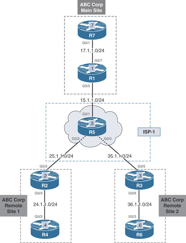
This lab should be conducted on the Enterprise Rack.
Lab Setup:
If you are using EVE-NG, and you have imported the EVE-NG topology from the EVE-NG-Topology folder, ignore the following and use Lab-1-Single Hub Single Cloud in the DMVPN folder in EVE-NG.
To copy and paste the initial configurations, go to the Initial-config folder → DMVPN folder → Lab-1.
Implement Phase 1
Design Goal
ABC Corp has expanded into two remote sites and needs connectivity between individual hosts at each site. In order to reduce cost, ABC Corp has decided against private WAN connectivity. The network engineers at ABC Corp have decided to leverage the Internet connection to ISP-1 at each site as the underlay for the VPN between the main site and remote sites.
Following are the detailed requirements:
R4 and R6 should be able to communicate with R7, located at the main campus.
R4 and R6 should be able to communicate with each other via R1.
Routing tables should contain the minimal amount of information required to perform routing between sites.
DMVPN Tunnel Configuration
The design goals outline basic connectivity requirements for the VPN. They specify that the main site should have direct connectivity with the remote sites. Any remote-site-to-remote-site traffic should first traverse the main site. These requirements fit perfectly into a Phase 1 DMVPN design. In the design, the main site router, R1, is the DMVPN hub and NHRP NHS. The remote site routers R2 and R3 are the DMVPN spoke routers and NHRP NHCs.
To implement this design, first create an mGRE tunnel on the hub R1. The configuration for this is simple. interface tunnel 100 creates the logical interface tunnel 100. ip address 100.1.1.1 255.255.255.0 assigns an IP address to the tunnel 100 interface. tunnel source 15.1.1.1 specifies the source of the GRE header. tunnel mode gre multipoint configures an mGRE tunnel interface on R1 to allow it to connect to both the spokes R2 and R3 over the same tunnel interface.
On R1:
R1(config)#interface tunnel 100
R1(config-if)#ip address 100.1.1.1 255.255.255.0
R1(config-if)#tunnel source 15.1.1.1
R1(config-if)#tunnel mode gre multipoint
With the mGRE tunnel configured, the next step is to configure NHRP to run on the mGRE tunnel interface to glue together the DMVPN. There are two main commands that will be issued on the hub. The first command enables NHRP operation on the mGRE interface, and the second sets up pseudo-multicast to support dynamic routing protocols.
First, ip nhrp network-id 100 is configured on the mGRE tunnel interface. This command enables NHRP on tunnel 100 on R1 and is locally significant. The command takes in a numerical value that defines an NHRP domain and can be used to differentiate between multiple NHRP domains. This value is only locally significant to the router, meaning it is not transmitted in the NHRP packets exchanged between nodes in the same domain. Therefore, it is not mandatory to use the same network ID on all the members of the same NHRP domain.
In cases where there are multiple NHRP domains on a router, matching NHRP network IDs between the members makes it easy to keep track of which NHRP networks have GRE interfaces configured.
The final NHRP-related command configured on the hub is ip nhrp map multicast dynamic. This command configures the hub to automatically add spoke NBMA addresses to the NHRP multicast table whenever a spoke registers. This command is essential to support dynamic routing protocols such as OSPF and EIGRP.
Note
The ip nhrp map multicast dynamic command and the static version of the same command are not necessary for BGP. BGP does not use multicast to establish peering relationship; rather, it uses explicit unicast communication over peering unicast IP addresses.
On R1:
R1(config)#interface tunnel 100
R1(config-if)#ip nhrp network-id 100
R1(config-if)#ip nhrp map multicast dynamic
With the ip nhrp network-id command configured, the hub can now generate NHRP messages.
The next step is to configure R2 and R3 as spoke routers. The configuration commands are similar to that of the hub, with one minor tweak. Unlike hub routers, DMVPN spoke routers do not enable multipoint GRE using the tunnel mode gre multipoint command for Phase 1 operation, as the design indicates. Instead, simple point-to-point tunnels are enough for strict Phase 1 operation.
Phase 1 operation does not permit a spoke-to-spoke tunnel, which would require the mGRE tunnel. Without any spoke-to-spoke tunnel, spoke R2 will form only a single spoke-to-spoke tunnel with the hub. Therefore, R2 is configured with the tunnel destination 15.1.1.1 command:
On R2:
R2(config)#interface tunnel 100
R2(config-if)#ip address 100.1.1.2 255.255.255.0
R2(config-if)#tunnel source 25.1.1.2
R2(config-if)#tunnel destination 15.1.1.1
Just as with the hub, after completing the base GRE configuration, NHRP should be enabled on the spokes as well. Much as with the hub, ip nhrp network-id 100 enables NHRP on the R2’s tunnel interface. The ip nhrp nhs 100.1.1.1 command is then issued to provide R2 with the address of the next hop server, R1. There is no need to configure ip nhrp map multicast commands on the spokes. Because the spokes are configured with static point-to-point tunnels, multicast traffic can be routed properly without maintaining NHRP multicast entries.
On R2:
R2(config)#interface tunnel 100
R2(config-if)#ip nhrp network-id 100
R2(config-if)#ip nhrp nhs 100.1.1.1
When you issue the ip nhrp nhs 100.1.1.1 command on the spoke R2, R2 registers with the hub R1.
Much like the above, the following configures a point-to-point GRE tunnel on R3 with the necessary NHRP-related commands to allow it to dynamically register with the hub R1:
On R3:
R3(config)#interface tunnel 100
R3(config-if)#ip address 100.1.1.3 255.255.255.0
R3(config-if)#ip nhrp network-id 100
R3(config-if)#ip nhrp nhs 100.1.1.1
R3(config-if)#tunnel source 35.1.1.3
R3(config-if)#tunnel destination 15.1.1.1
The show dmvpn output on R1 confirms that R1 has dynamically (as indicated with a D attribute) learned the NBMA-to-tunnel IP mapping of spokes R2 and R3:
R1#show dmvpn | begin Peer
Type:Hub, NHRP Peers:2,

 # Ent  Peer NBMA Addr Peer Tunnel Add State  UpDn Tm Attrb
 ----- --------------- --------------- ----- -------- -----
     1 25.1.1.2              100.1.1.2    UP 00:05:07     D !SPOKE R2
     1 35.1.1.3              100.1.1.3    UP 00:02:41     D !SPOKE R3
At this point, a traceroute to the tunnel IP addresses in the DMVPN verifies reachability.
The following traceroute output confirms reachability between the spokes R2 and R3 to the hub R1:
On R2:
R2#traceroute 100.1.1.1 probe 1
Type escape sequence to abort.
Tracing the route to 100.1.1.1
VRF info: (vrf in name/id, vrf out name/id)
  1 100.1.1.1 15 msec
On R3:
R2#traceroute 100.1.1.1 probe 1
Type escape sequence to abort.
Tracing the route to 100.1.1.1
VRF info: (vrf in name/id, vrf out name/id)
  1 100.1.1.1 17 msec
Similarly, a traceroute from R2 to R3 traverses the hub, confirming Phase 1 operation:
On R2:
R2#traceroute 100.1.1.3 probe 1
Type escape sequence to abort.
Tracing the route to 100.1.1.3
VRF info: (vrf in name/id, vrf out name/id)
  1 100.1.1.1 45 msec
  2 100.1.1.3 10 msec
With DMVPN Phase 1 successfully set up between R1, R2, and R3, the next part of the task involves advertising the host networks at each site into an overlay protocol. The following section demonstrates the configuration and implementation of OSPF, EIGRP, and BGP as overlay protocols.
As mentioned in the introduction section, when implementing DMVPN Phase 1, the routing is important only to pull the VPN traffic through the tunnel. Because of the limitations of the point-to-point GRE tunnel on the spoke routers, traffic will always be pulled toward the hub, regardless of what the routing table entries reveal. Spoke routers will not resolve spoke-to-spoke tunnels even if next hops are preserved when advertised from the hub router.
Implement OSPF
When implementing DMVPN with OSPF as the overlay routing protocol, an engineer needs to be wary of how the different OSPF network types influence the resulting routing table on each OSPF router.
OSPF’s network types do not technically play a role in determining the routing in the DMVPN network for Phase 1. Each of the network types can be used to provide the appropriate communication. Also, a main characteristic of DMVPN Phase 1 is the hub and spoke capability only, meaning all traffic destined from a spoke to another spoke always traverses the hub. Because of this, no special consideration needs to be made for preservation of next hops. OSPF network types are categorized as:
Broadcast
Point-to-point
Point-to-multipoint
Non-broadcast (NBMA)
Point-to-multipoint, non-broadcast
Any of the OSPF network types can be used to provide the routing in a Phase 1 DMVPN implementation. All non-broadcast network types will be ignored. Their requirement of static neighbor communication does not fit well with the DMVPN design philosophy. Hence, only the broadcast, point-to-point, and point-to-multipoint network types will be implemented in this lab.
Broadcast Network Type
Before beginning the broadcast network type configuration, two main points need to be addressed:
Broadcast network type preserves the next hop IP address.
Broadcast network type elects a DR/BDR.
The broadcast network type preserves the next hop IP address when OSPF adds routes to the routing table. In the topology diagram at the beginning of this lab, this means when R3 advertises 36.1.1.0/24 to the hub R1, R1 retains the actual next hop IP address 100.1.1.3 when advertising the route to the spoke R2 and vice versa. As a result, the network 36.1.1.0/24 is associated with the next hop IP address 100.1.1.3 on R2.
However, in Phase 1 DMVPN with point-to-point GRE tunnels, this does not force a spoke-to-spoke NHRP resolution to occur and hence does not present any problem. What should be considered, though, is the placement of the OSPF DR in the DMVPN.
Spokes only form OSPF adjacencies with the hub and therefore can only become fully adjacent with the hub router. On a broadcast network, routers only become fully adjacent with the DR on the segment. If the hub is not chosen as the DR on the segment, then the spoke routers will be unable to solve the SPF tree. Thus, for a correct design, the hub R1 should be configured as the OSPF DR, and the spoke routers R2 and R3 should be made ineligible to become either DR or BDR. This can be achieved by setting the OSPF priority to 0 on the spokes R2 and R3.
The following configuration establishes OSPF adjacencies between R1 and R2 and between R1 and R3. The default OSPF network type point-to-point on the tunnel is changed to broadcast network type with the ip ospf network broadcast command on the tunnel 100 interface. The tunnel interfaces are then assigned to the OSPF process 100 to run in Area 0. Finally, R2 and R3 have their OSPF priorities set to 0, using the ip ospf priority 0 command on their tunnel interfaces.
On R1:
R1(config)#interface tunnel 100
R1(config-if)#ip ospf network broadcast
R1(config-if)#ip ospf 100 area 0
On R2:
R2(config)#interface tunnel 100
R2(config-if)#ip ospf network broadcast
R2(config-if)#ip ospf priority 0
R2(config-if)#ip ospf 100 area 0
You should see the following console message:
%OSPF-5-ADJCHG: Process 100, Nbr 100.1.1.1 on Tunnel100 from LOADING
to FULL, Loading Done
On R3:
R3(config)#interface tunnel 100
R3(config-if)#ip ospf network broadcast
R3(config-if)#ip ospf priority 0
R3(config-if)#ip ospf 100 area 0
You should see the following console message:
%OSPF-5-ADJCHG: Process 100, Nbr 100.1.1.1 on Tunnel100 from LOADING
to FULL, Loading Done
The show ip ospf neighbor detail command output on R1 now confirms the OSPF adjacencies between R1 and R2 and R1 and R3, along with certain other key details. Notice how the output indicates that the neighbor priority value is 0, and the DR is 100.1.1.1.
On R1:
R1#show ip ospf neighbor detail

 Neighbor 100.1.1.2, interface address 100.1.1.2
    In the area 0 via interface Tunnel100
    Neighbor priority is 0, State is FULL, 6 state changes
    DR is 100.1.1.1 BDR is 0.0.0.0
    Options is 0x12 in Hello (E-bit, L-bit)
    Options is 0x52 in DBD (E-bit, L-bit, O-bit)
    LLS Options is 0x1 (LR)
    Dead timer due in 00:00:31
    Neighbor is up for 00:04:27
    Index 1/1/1, retransmission queue length 0, number of
retransmission 3

    First 0x0(0)/0x0(0)/0x0(0) Next 0x0(0)/0x0(0)/0x0(0)
    Last retransmission scan length is 1, maximum is 1
    Last retransmission scan time is 0 msec, maximum is 0 msec
 Neighbor 100.1.1.3, interface address 100.1.1.3
    In the area 0 via interface Tunnel100
    Neighbor priority is 0, State is FULL, 6 state changes
    DR is 100.1.1.1 BDR is 0.0.0.0
    Options is 0x12 in Hello (E-bit, L-bit)
    Options is 0x52 in DBD (E-bit, L-bit, O-bit)
    LLS Options is 0x1 (LR)
    Dead timer due in 00:00:39
    Neighbor is up for 00:02:03
    Index 2/2/2, retransmission queue length 0, number of
retransmission 0
    First 0x0(0)/0x0(0)/0x0(0) Next 0x0(0)/0x0(0)/0x0(0)
    Last retransmission scan length is 0, maximum is 0
    Last retransmission scan time is 0 msec, maximum is 0 msec
The next step is to advertise the host networks at the main campus and remote sites into OSPF process 100 for area 0. To do so, simply enable OSPF process 100 for area 0 on the respective VLAN interfaces on R1, R2, and R3. These VLANs are connected to end hosts; therefore, other OSPF-speaking routers are not expected to be connected to those LANs. Accidental OSPF adjacencies can be prevented from forming on these interfaces by making them passive using the passive-interface command in OSPF configuration mode:
On R1:
R1(config)#interface g0/7
R1(config-if)#ip ospf 100 area 0

R1(config-if)#router ospf 100
R1(config-router)#passive-interface g0/5
On R2:
R2(config)#interface g0/4
R2(config-if)#ip ospf 100 area 0

R2(config-if)#router ospf 100
R2(config-router)#passive-interface g0/5
On R3:
R3(config)#interface g0/6
R3(config-if)#ip ospf 100 area 0

R3(config-if)#router ospf 100
R3(config-router)#passive-interface g0/5
With the above configurations complete, the show ip route ospf command at each site shows that the routers have installed OSPF routes for host networks at the remote sites:
On R1:
R1#show ip route ospf | begin Gate
Gateway of last resort is not set

      24.0.0.0/24 is subnetted, 1 subnets
O        24.1.1.0 [110/1001] via 100.1.1.2, 01:12:00, Tunnel100
      36.0.0.0/24 is subnetted, 1 subnets
O        36.1.1.0 [110/1001] via 100.1.1.3, 01:10:30, Tunnel100
On R2:
R2#show ip route ospf | begin Gate
Gateway of last resort is not set

      17.0.0.0/24 is subnetted, 1 subnets
O        17.1.1.0 [110/1001] via 100.1.1.1, 01:14:34, Tunnel100
      36.0.0.0/24 is subnetted, 1 subnets
O        36.1.1.0 [110/1001] via 100.1.1.3, 01:11:25, Tunnel100
On R3:
R3#show ip route ospf | begin Gate
Gateway of last resort is not set

      17.0.0.0/24 is subnetted, 1 subnets
O        17.1.1.0 [110/1001] via 100.1.1.1, 01:15:24, Tunnel100
      24.0.0.0/24 is subnetted, 1 subnets
O        24.1.1.0 [110/1001] via 100.1.1.2, 01:14:21, Tunnel100
As mentioned earlier, the next hop on R2 for R3’s host network 36.1.1.0/24 is R3’s tunnel IP address 100.1.1.3. Similarly, the next hop on R3 for R2’s host network is R2’s tunnel IP address 100.1.1.2. The same can be confirmed with the show ip cef output on R2 and R3, as shown below:
R2#show ip cef 36.1.1.0

36.1.1.0/24
  nexthop 100.1.1.3 Tunnel100

R3#show ip cef 24.1.1.0

24.1.1.0/24
  nexthop 100.1.1.2 Tunnel100
Next a traceroute is performed from R4 to R7 at the main site and from R4 to R6 at the remote site 2. As evidenced below, the traffic always traverses the hub router, as should occur in Phase 1 DMVPN:
On R4:
R4#traceroute 17.1.1.7 probe 1

Type escape sequence to abort.
Tracing the route to 17.1.1.7
VRF info: (vrf in name/id, vrf out name/id)
  1 24.1.1.2 13 msec
  2 100.1.1.1 9 msec
  3 17.1.1.7 12 msec

R4#traceroute 36.1.1.6 probe 1

Type escape sequence to abort.
Tracing the route to 36.1.1.6
VRF info: (vrf in name/id, vrf out name/id)
  1 24.1.1.2 9 msec
  2 100.1.1.1 11 msec
  3 100.1.1.3 42 msec
  4 36.1.1.6 12 msec
Point-to-Point and Point-to-Multipoint Network Types
The following points should be addressed when configuring the point-to-point network type for DMVPN:
Next-hop IP addresses are not preserved.
Point-to-point network type does not allow multiple neighbors on a single interface.
Point-to-point and point-to-multipoint use different hello interval timers.
Unlike with the broadcast network type, point-to-point and point-to-multipoint network types do not preserve the next hop IP addresses of the spokes. Refer to the topology diagram at the beginning of this lab once again. The next hop IP address for the 36.1.1.0/24 network on R2 will be R1’s tunnel IP address 100.1.1.1.
OSPF’s point-to-point network type does not allow multiple neighbors on the tunnel interface. So this network type can be used on the spokes as R2 and R3 only form OSPF adjacencies with the hub R1 and not with each other. The hub R1, on the other hand, is required to form multiple OSPF adjacencies—one each with R2 and R3. As such, the point-to-multipoint network type should be configured on R1’s tunnel 100 interface.
A slight tweak related to the hello interval is required when combining point-to-point and point-to-multipoint on the same overlay OSPF domain. The default hello and dead intervals differ on these network types, and OSPF requires that these timers match on all nodes. The point-to-multipoint hello timer is 30 seconds by default, whereas the point-to-point hello timer is 10 seconds by default. So, a key configuration change to keep in mind when combining point-to-point and point-to-multipoint network types is ensuring that the hello parameters match. It is easiest to change the hello timer on R1 to match the spokes R2 and R3, since it only requires one configuration command on the hub router.
At the main campus, R1 is configured to run its tunnel 100 interface as point-to-multipoint with the ip ospf network point-to-multipoint command. The tunnel is then assigned to OSPF process 100 to run in Area 0. In addition, 17.1.1.0/24, the link that connects R1 to R7, is already advertised into OSPF, and the interface is declared passive.
On R1:
R1(config)#interface tunnel 100
R1(config-if)#ip ospf network point-to-multipoint
To verify the configuration:
R1#show ip ospf interface tunnel 100 | include Network|Timer


  Process ID 100, Router ID 100.1.1.1, Network Type POINT_TO_
MULTIPOINT, Cost: 1000
  Timer intervals configured, Hello 30, Dead 120, Wait 120, Retransmit 5
Note in the show ip ospf interface tunnel 100 output above that the hello interval is set to 30 seconds, which is the default for point-to-multipoint network type. This timer is changed to match the hello interval of 10 seconds, which is the default on the spokes’ point-to-point interface with the ip ospf hello-interval command. Modifying the hello interval time automatically resets the dead interval to four times the hello interval timer:
On R1:
R1(config)#interface tunnel 100
R1(config-if)#ip ospf hello-interval 10
To verify the configuration:
R1#show ip ospf interface tunnel 100 | include Timer

  Timer intervals configured, Hello 10, Dead 40, Wait 40, Retransmit 5
You should see the following console messages:
%OSPF-5-ADJCHG: Process 100, Nbr 100.1.1.3 on Tunnel100 from LOADING
to FULL, Loading Done

%OSPF-5-ADJCHG: Process 100, Nbr 100.1.1.2 on Tunnel100 from LOADING
to FULL, Loading Done
R2’s and R3’s tunnel interfaces are already configured with ip ospf 100 area 0, and the default OSPF network type on GRE tunnel interfaces is point-to-point. However, the network type of the tunnel 100 interface on the spoke routers was changed in the previous scenario to broadcast. It must be changed to point-to-point with the ip ospf network point-to-point command:
On R2 and R3:
Rx(config)#interface tunnel 100
Rx(config-if)#ip ospf network point-to-point
You should see the following console messages:
%OSPF-5-ADJCHG: Process 100, Nbr 100.1.1.1 on Tunnel100 from FULL to
DOWN, Neighbor Down: Interface down or detached


%OSPF-5-ADJCHG: Process 100, Nbr 100.1.1.1 on Tunnel100 from LOADING
to FULL, Loading Done
The show ip ospf neighbor output below shows R1’s OSPF adjacencies with the spokes R2 and R3 over the tunnel 100 interface:
R1#show ip ospf neighbor

Neighbor ID     Pri   State         Dead Time   Address         Interface
100.1.1.2         0   FULL/         00:00:39    100.1.1.2       Tunnel100
100.1.1.3         0   FULL/         00:00:32    100.1.1.3       Tunnel100
The show ip route ospf command at each site shows that the routers have installed OSPF routes for each other’s host networks. R2 and R3 use R1’s tunnel IP address 100.1.1.1 as the next hop address for 36.1.1.0/24 and 24.1.1.0/24, respectively. As mentioned, this is a characteristic of point-to-point /point-to-multipoint network types, where the hub does not preserve the true next hop. The show ip cef output confirms this:
On R1:
R1#show ip route ospf | begin Gate
Gateway of last resort is not set

      24.0.0.0/24 is subnetted, 1 subnets
O        24.1.1.0 [110/1001] via 100.1.1.2, 00:04:03, Tunnel100
      36.0.0.0/24 is subnetted, 1 subnets
O        36.1.1.0 [110/1001] via 100.1.1.3, 00:01:34, Tunnel100
On R2:
R2#show ip route ospf | begin Gate
Gateway of last resort is not set

      17.0.0.0/24 is subnetted, 1 subnets
O        17.1.1.0 [110/1001] via 100.1.1.1, 00:05:06, Tunnel100
      36.0.0.0/24 is subnetted, 1 subnets
O        36.1.1.0 [110/2001] via 100.1.1.1, 00:02:37, Tunnel100
      100.0.0.0/8 is variably subnetted, 3 subnets, 2 masks
O        100.1.1.1/32 [110/1000] via 100.1.1.1, 00:05:06, Tunnel100


 R2#show ip cef 36.1.1.0

36.1.1.0/24
  nexthop 100.1.1.1 Tunnel100
On R3:
R3#show ip route ospf | begin Gate
Gateway of last resort is not set

      17.0.0.0/24 is subnetted, 1 subnets
O        17.1.1.0 [110/1001] via 100.1.1.1, 00:03:44, Tunnel100
      24.0.0.0/24 is subnetted, 1 subnets
O        24.1.1.0 [110/2001] via 100.1.1.1, 00:03:44, Tunnel100
      100.0.0.0/8 is variably subnetted, 3 subnets, 2 masks
O        100.1.1.1/32 [110/1000] via 100.1.1.1, 00:03:44, Tunnel100

R3#show ip cef 24.1.1.0

24.1.1.0/24
  nexthop 100.1.1.1 Tunnel100
Note
Although the spokes form a single adjacency with the hub, the point-to-multi-point network type can be configured on their tunnel interfaces as well. This configuration would not require modifying the hello interval on either the hub or the spokes. Spokes will still show a single adjacency with the hub because, due to the point-to-point GRE tunnel, the spokes will only send multicast hellos to the hub router.
Also, notice the /32 prefixes (100.1.1.1/32) installed in the RIB for the DMVPN tunnel interfaces. This is a side effect of the point-to-multipoint network types. When these network types are used, OSPF models the IP address on the link it is enabled on (in this case, the tunnel interface) as a /32 stub network. Doing so provides connectivity whenever both ends of an OSPF point-to-point link are not in the same subnet. This can occur when unnumbered point-to-point links are used. Broadcast network types do not exhibit this behavior.
Summarization with OSPF
OSPF forces the network to be segmented into a collection of areas. In order for two routers to become OSPF neighbors, the link connecting them must be in the same area. Routers participating in the same area share complete routing information about all networks that reside in that area in link-state advertisements (LSAs). LSAs are compiled on each individual router to form the link-state database (LSDB). The LSDB of an area contains all routers, all networks connected to those routers, and all router-to-router connections. The result is an accurate graph of the interconnections of the area. To calculate routes in the routing table, the OSPF router runs the SPF algorithm to calculate shortest paths. This is all made possible because of the complete information contained in the LSDB.
OSPF domains can consist of multiple areas creating logical groupings of routers. A router can participate in multiple areas, creating a separate LSDB for each area it participates in. Such routers are called ABRs. ABRs glue together the OSPF domain by advertising routing information from one area to another in distance vector fashion. Such routes are called inter-area routes.
Routing information within an area cannot be summarized or reduced as doing so would break the route calculation process. Therefore, the routing tables of all routers within an area will contain all prefixes reachable within that area. This can severely limit the degree of summarization that OSPF can achieve when implementing DMVPN.
Keeping the above in mind, in order to exchange OSPF routing information, the hub R1 and spoke routers R2 and R3 must become OSPF neighbors. To do so, they must all exist in the same OSPF area and carry the limitation with summarization mentioned above. This limits the hub from being able to send summarized information of the host networks at R2 to R3 and vice versa.
There is, however, a workaround to this that involves performing summarization at the spokes. The interfaces connecting to the end hosts at each remote site can be placed into a separate area. As a result, R2 and R3 would now function as ABRs as they are connected to the backbone and non-backbone areas. This would give them the ability to perform inter-area summarization with the area range command, as shown below:
To demonstrate this, let’s place the link connecting R2 and R4 into Area 2 and the link connecting R3 and R6 into Area 3:
On R2:
R2(config)#interface g0/4
R2(config-if)#ip ospf 100 area 2
On R3:
R3(config)#interface g0/6
R3(config-if)#ip ospf 100 area 3
Notice how the show ip ospf output shows R2 and R3 to be the ABRs:
On R2:
R2#show ip ospf | include It is an

 It is an area border router
On R3:
R3#show ip ospf | include It is an

 It is an area border router
Next, the area range command summarizes the host networks to /8 on R2 and R3:
On R2:
R2(config)#router ospf 100
R2(config-router)#area 2 range 24.0.0.0 255.0.0.0
On R3:
R3(config)#router ospf 100
R3(config-router)#area 3 range 36.0.0.0 255.0.0.0
On observing the routing tables on R2 and R3, you see that specific 24.1.1.0/24 and 36.1.1.0/24 routes have been suppressed and have been replaced with the /8 summaries for each other’s host networks:
R3#show ip route ospf | begin Gate
Gateway of last resort is not set

      17.0.0.0/24 is subnetted, 1 subnets
O        17.1.1.0 [110/1001] via 100.1.1.1, 00:02:40, Tunnel100
O IA  24.0.0.0/8 [110/2001] via 100.1.1.1, 00:02:40, Tunnel100
      36.0.0.0/8 is variably subnetted, 3 subnets, 3 masks
O        36.0.0.0/8 is a summary, 00:02:40, Null0
      100.0.0.0/8 is variably subnetted, 3 subnets, 2 masks
O        100.1.1.1/32 [110/1000] via 100.1.1.1, 00:02:40, Tunnel100
On R2:
R2#show ip route ospf | begin Gate
Gateway of last resort is not set

      17.0.0.0/24 is subnetted, 1 subnets
O        17.1.1.0 [110/1001] via 100.1.1.1, 00:03:55, Tunnel100

      24.0.0.0/8 is variably subnetted, 3 subnets, 3 masks
O        24.0.0.0/8 is a summary, 00:03:55, Null0
O IA  36.0.0.0/8 [110/2001] via 100.1.1.1, 00:03:36, Tunnel100
      100.0.0.0/8 is variably subnetted, 3 subnets, 2 masks
O        100.1.1.1/32 [110/1000] via 100.1.1.1, 00:03:55, Tunnel100
Implement EIGRP
Implementing EIGRP in DMVPN Phase 1 is pretty straightforward. First, EIGRP is enabled on the tunnel 100 interfaces on R1, R2, and R3 with the network command under the EIGRP router configuration mode. This results in an EIGRP adjacency between R1 and R2 and between R1 and R3. The host networks at the main campus and remote sites are also advertised into EIGRP with the network statement. In addition, the interfaces facing R4, R6, and R7 are made passive interfaces to prevent any EIGRP adjacencies from forming over them. Before you configure EIGRP, you should remove OSPF on these three routers:
On R1:
R1(config)#no router ospf 100

R1(config)#interface tunnel 100
R1(config-if)#no ip ospf network point-to-multipoint

R1(config)#router eigrp 100
R1(config-router)#network 17.1.1.1 0.0.0.0
R1(config-router)#network 100.1.1.1 0.0.0.0
R1(config-router)#passive-interface g0/5
On R2:
R2(config)#no router ospf 100

R2(config)#router eigrp 100
R2(config-router)#network 100.1.1.2 0.0.0.0
R2(config-router)#network 24.1.1.2 0.0.0.0
R2(config-router)#passive-interface g0/5
You should see the following console message:
%DUAL-5-NBRCHANGE: EIGRP-IPv4 100: Neighbor 100.1.1.1 (Tunnel100) is
up: new adjacency
On R3:
R3(config)#no router ospf 100

R3(config)#router eigrp 100
R3(config-router)#network 36.1.1.3 0.0.0.0
R3(config-router)#network 100.1.1.3 0.0.0.0
R3(config-router)#passive-interface g0/5
You should see the following console message:
%DUAL-5-NBRCHANGE: EIGRP-IPv4 100: Neighbor 100.1.1.1 (Tunnel100) is
up: new adjacency
The show ip eigrp 100 neighbor output on R1 shows the EIGRP neighborships between R1 and R2 and R1 and R3 over the tunnel 100 interface:
On R1:
R1#show ip eigrp 100 neighbors
EIGRP-IPv4 Neighbors for AS(100)

H   Address            Interface              Hold Uptime   SRTT   RTO  Q  Seq
                                               (sec)         (ms)       Cnt
Num
1   100.1.1.3          Tu100                    11 00:02:22   12  1434  0  3
0   100.1.1.2          Tu100                    14 00:06:21   10  1434  0  4
The routing table on R1 shows that R1 has learned of the host networks 24.1.1.0/24 and 36.1.1.0/24 from R2 and R3, respectively:
On R1:
R1#show ip route eigrp 100 | begin Gate
Gateway of last resort is not set

      24.0.0.0/24 is subnetted, 1 subnets
D        24.1.1.0 [90/26880256] via 100.1.1.2, 00:03:06, Tunnel100
      36.0.0.0/24 is subnetted, 1 subnets
D        36.1.1.0 [90/26880256] via 100.1.1.3, 00:01:56, Tunnel100
However, the routing tables on R2 and R3 reveal that the spokes have only learned a route to the host network 17.1.1.0/24 at the main site. Neither spoke contains the other spoke’s host network (36.1.1.0/24 and 24.1.1.0/24):
On R2:
R2#show ip route eigrp 100 | begin Gate
Gateway of last resort is not set

      17.0.0.0/24 is subnetted, 1 subnets
D        17.1.1.0 [90/26880256] via 100.1.1.1, 00:09:43, Tunnel100
On R3:
R3#show ip route eigrp 100 | begin Gate
Gateway of last resort is not set

      17.0.0.0/24 is subnetted, 1 subnets
D        17.1.1.0 [90/26880256] via 100.1.1.1, 00:06:45, Tunnel100
As mentioned in the introduction section of this lab, EIGRP’s split-horizon feature which is enabled by default will prevent the hub router R1 from advertising prefixes between the spokes. The show ip eigrp 100 interface detail output below verifies that split horizon is enabled on R1’s tunnel interface
On R1:
R1#show ip eigrp 100 interfaces detail | include Split

  Split-horizon is enabled
The spli-horizon feature can be turned off with the no ip split-horizon eigrp 100 command on the tunnel interface on R1. As a result, R1 advertises the host networks at the remote sites learned via EIGRP to R2 and R3. By default, the hub sets the next hop of advertised prefixes to itself, as shown below:
On R1:
R1(config)#interface tunnel 100
R1(config-if)#no ip split-horizon eigrp 100
You should see the following console messages:
%DUAL-5-NBRCHANGE: EIGRP-IPv4 100: Neighbor 100.1.1.3 (Tunnel100) is
resync: split horizon changed

%DUAL-5-NBRCHANGE: EIGRP-IPv4 100: Neighbor 100.1.1.2 (Tunnel100) is
resync: split horizon changed
On R2:
R2#show ip route eigrp 100 | begin Gate
Gateway of last resort is not set

      17.0.0.0/24 is subnetted, 1 subnets
D        17.1.1.0 [90/26880256] via 100.1.1.1, 00:16:01, Tunnel100
      36.0.0.0/24 is subnetted, 1 subnets
D        36.1.1.0 [90/28160256] via 100.1.1.1, 00:00:52, Tunnel100
On R3:
R3#show ip route eigrp 100 | begin Gate
Gateway of last resort is not set

      17.0.0.0/24 is subnetted, 1 subnets
D        17.1.1.0 [90/26880256] via 100.1.1.1, 00:12:48, Tunnel100
      24.0.0.0/24 is subnetted, 1 subnets
D        24.1.1.0 [90/28160256] via 100.1.1.1, 00:01:38, Tunnel100
The design goals for this lab, however, indicate that R1 should send as much summary information to the spokes as possible. To complete this task, R1 can send a default summary route to the spokes. Routing will continue to function properly because the spokes still send specific prefixes to the hub. Spokes will route to the hub for all prefixes for which they do not have a specific prefix (in this case, each other’s LANs), and the hub can properly forward the traffic.
With the hub sending a default summary route, the split-horizon configuration becomes inconsequential. The hub no longer needs to forward spoke prefixes between other spokes to provide proper routing. To prove this point, split horizon is turned back on with the ip split-horizon eigrp 100 command. R1 is then configured to send a default route via EIGRP to the spokes with the ip summary-address eigrp 100 0.0.0.0 0.0.0.0 command:
On R1:
R1(config)#interface tunnel 100
R1(config-if)#ip split-horizon eigrp 100
R1(config-if)#ip summary-address eigrp 100 0.0.0.0 0.0.0.0
The following output reveals that the default route entries on R2 and R3 use the tunnel 100 interface as the exit point:
On R2 and R3:
Rx#show ip route eigrp 100 | begin Gate
Gateway of last resort is 100.1.1.1 to network 0.0.0.0

D*    0.0.0.0/0 [90/26880256] via 100.1.1.1, 00:01:50, Tunnel100
Following traceroutes confirm reachability between the sites. Because this is a Phase 1 implementation, traffic between spokes always traverses the hub:
On R4:
R4#traceroute 17.1.1.7 probe 1
Type escape sequence to abort.

Tracing the route to 17.1.1.7
VRF info: (vrf in name/id, vrf out name/id)
  1 24.1.1.2 6 msec
  2 100.1.1.1 8 msec
  3 17.1.1.7 13 msec
On R6:
R6#traceroute 17.1.1.7 probe 1
Type escape sequence to abort.

Tracing the route to 17.1.1.7
VRF info: (vrf in name/id, vrf out name/id)
  1 36.1.1.3 5 msec
  2 100.1.1.1 11 msec
  3 17.1.1.7 12 msec

R4#traceroute 36.1.1.6 probe 1

Type escape sequence to abort.
Tracing the route to 36.1.1.6
VRF info: (vrf in name/id, vrf out name/id)
  1 24.1.1.2 9 msec
  2 100.1.1.1 11 msec
  3 100.1.1.3 42 msec
  4 36.1.1.6 12 msec
Implement iBGP
Before moving on to configure iBGP peerings between R1 and R2 and between R1 and R3, certain key points need to be addressed:
iBGP peers do not advertise paths learned from an iBGP peer to another iBGP peer.
Traditional BGP configurations require static neighbor configurations.
In BGP, the local router will pick the best prefixes and advertise the best path to its neighbors. However, if the prefix has the route type internal, then the local router will not advertise this path to its other internal peers. This is because within an AS, BGP does not update the AS_PATH information when sending updates to internal peers. The fact that the AS_PATH is not updated eliminates BGP’s primary loop-prevention mechanism: denying prefixes whose AS_PATH contains the local ASN. As a result, iBGP neighbors do not advertise received iBGP routes with each other.
The show ip route x.x.x.x output can be used to verify the route type. If a network is learned from an iBGP peer, the type shows up as internal, as shown below:
R1#show ip route 36.1.1.0

Routing entry for 36.1.1.0/24
  Known via "bgp 100", distance 200, metric 0, type internal
  Last update from 100.1.1.3 00:00:40 ago
  Routing Descriptor Blocks:
  * 100.1.1.3, from 100.1.1.3, 00:00:40 ago
      Route metric is 0, traffic share count is 1
      AS Hops 0
      MPLS label: none
If a network is learned from an eBGP peer, the type shows up as external, as shown below:
R1#show ip route 36.1.1.0

Routing entry for 36.1.1.0/24
  Known via "bgp 100", distance 20, metric 0
  Tag 300, type external
  Last update from 100.1.1.3 00:00:07 ago
  Routing Descriptor Blocks:
  * 100.1.1.3, from 100.1.1.3, 00:00:07 ago
      Route metric is 0, traffic share count is 1
      AS Hops 1
      Route tag 300
      MPLS label: none
Correlating this to the design topology, whenever the hub R1 receives host network 24.1.1.0/24 as a BGP prefix from iBGP peer R2, R1 does not advertise the 24.1.1.0/24 network down to the other spoke R3 and vice versa. One of the ways to overcome this constraint is to configure hub R1 as a route reflector to host the control plane for the iBGP topology. As a route reflector, R1 receives the host networks from R2 and R3 at the remote site, selects them as the best path, and advertises them down to each other. This configuration forces a similar operation to setting the OSPF DR from the OSPF section of the configuration.
BGP peers are typically created using static neighbor commands for each specific BGP speaker that should become a peer with the local BGP speaker. This configuration presents some problems when applied to DMVPN specifically. The task does not directly address this issue, but it is something that should be thought of when implementing a DMVPN solution using BGP. The reason behind this configuration lies in BGP’s use of TCP to form peerings.
BGP uses TCP as its transport for forming peering relationships between routers. When a BGP router attempts to peer with another BGP router, it first must initiate a TCP connection by sending a TCP SYN packet to the remote peer. The SYN will be destined to the well-known BGP TCP port 179. If the remote peer accepts the SYN packet, it responds accordingly with a SYN-ACK. The BGP router that initiated the request responds with an ACK packet, completing the TCP connection. This process is known as the TCP three-way handshake.
In a typical BGP configuration, potential BGP peers are manually configured with neighbor statements in BGP configuration mode. The BGP router attempts to open a TCP connection with each peer periodically, with the intention of forming a BGP peering relationship.
In the topology diagram at the beginning of this lab, R1 is the DMVPN hub and needs to form iBGP peering sessions with the spoke routers R2 and R3. For scalable designs, R1 does not know how many DMVPN spokes are connected to the DMVPN until the spokes register with it when they come online. While it is fully possible for an administrator to manually configure the peering addresses, doing so would violate the dynamic intention of DMVPN. To circumvent this, there is another feature that can be used: BGP’s dynamic neighbor feature. With the BGP dynamic neighbor feature, the hub can simply listen for TCP connections from a specified range of IP addresses. When it receives one, it automatically begins a peering session with that neighbor.
The spokes R2 and R3 will be manually configured with the IP address of the hub router. Once this is configured, R2 and R3 will begin sending TCP SYN packets to the hub with the destination port 179.
Taking advantage of the fact that spokes send connection attempts to the hub R1, R1 can be configured to simply listen for such connection attempts from prospective spoke routers and respond accordingly. When spokes send their TCP SYN packets to the hub, they are automatically considered TCP clients for the TCP connection, and the hub is the TCP server.
The bgp listen-range command configured on hub R1 will allow the hub router to listen for incoming BGP connection attempts from a specific IP address range. R1 applies a peer group to all connections originating from that IP address range.
With that established, the following configurations allow for iBGP peerings between the route reflector R1 and R2 and R1 and R3.
First, a peer group is created on the hub that contains the appropriate configuration information for the dynamic peers (in this case, the ASN and route reflector client status), which are the spokes. This peer group is linked to the bgp listen-range command for the 100.1.1.0/24 subnet (the subnet the peers will come from). R2 and R3 are configured with neighbor statements to peer R1’s tunnel IP address 100.1.1.1. Finally, the network command is used at each site to advertise the host networks into BGP:
On R1, R2, and R3:
Rx(config)#no router eigrp 100
On R1:
R1(config)#router bgp 100
R1(config-router)#neighbor spokes peer-group
R1(config-router)#neighbor spokes remote-as 100
R1(config-router)#bgp listen range 100.1.1.0/24 peer-group spokes

R1(config-router)#address-family ipv4
R1(config-router-af)#neighbor spokes activate
R1(config-router-af)#neighor spokes route-reflector-client
R1(config-router-af)#network 17.1.1.0 mask 255.255.255.0
On R2:
R2(config)#router bgp 100
R2(config-router)#neighbor 100.1.1.1 remote-as 100

R2(config-router)#address-family ipv4
R2(config-router-af)#network 24.1.1.0 mask 255.255.255.0
R2(config-router-af)#neighbor 100.1.1.1 activate
You should see the following console message:
%BGP-5-ADJCHANGE: neighbor 100.1.1.1 UpOn R3:
R3(config)#router bgp 100
R3(config-router)#neighbor 100.1.1.1 remote-as 100

R3(config-router)#address-family ipv4
R3(config-router-af)#neighbor 100.1.1.1 activate
R3(config-router-af)#network 36.1.1.0 mask 255.255.255.0
You should see the following console message:
%BGP-5-ADJCHANGE: neighbor 100.1.1.1 UpThe following output from the show ip bgp summary command on R1 shows that peering’s to the iBGP neighbors 100.1.1.2 and 100.1.1.3 was dynamically established:
On R1:
R1#show ip bgp summary | begin Nei

Neighbor     V   AS MsgRcvd MsgSent   TblVer  InQ OutQ Up/Down  State/PfxRcd
*100.1.1.2   4  100      10      10        4    0    0 00:05:04
1
*100.1.1.3   4  100       6      11        4    0    0 00:02:35
1
* Dynamically created based on a listen range command
Dynamically created neighbors: 2, Subnet ranges: 1

BGP peergroup spokes listen range group members:
  100.1.1.0/24

Total dynamically created neighbors: 2/(100 max), Subnet ranges: 1
After establishing the peering relationships with the hub and exchanging BGP routing information, R2 and R3 learn each other’s host networks via BGP:
On R1:
R1#show ip bgp | begin Net

     Network          Next Hop            Metric LocPrf Weight Path
 *>   17.1.1.0/24      0.0.0.0                  0         32768 i
 *>i  24.1.1.0/24      100.1.1.2                0    100      0 i
 *>i  36.1.1.0/24      100.1.1.3                0    100      0 i
On R2:
R2#show ip bgp | begin Net

     Network          Next Hop            Metric LocPrf Weight Path
 *>i  17.1.1.0/24      100.1.1.1                0    100      0 i
 *>   24.1.1.0/24      0.0.0.0                  0         32768 i
 *>i  36.1.1.0/24      100.1.1.3                0    100      0 i
On R3:
R3#show ip bgp | begin Net

     Network          Next Hop            Metric LocPrf Weight Path
 *>i  17.1.1.0/24      100.1.1.1                0    100      0 i
 *>i  24.1.1.0/24      100.1.1.2                0    100      0 i
 *>   36.1.1.0/24      0.0.0.0                  0         32768 i
The BGP and RIB entries on the spokes R2 and R3 for each other’s host network point to each other’s tunnel IP addresses. This is as expected because route reflectors do not modify the next hop value. As already mentioned in the OSPF section, this shouldn’t present any problem because the tunnels on the spokes are point-to-point GRE tunnels:
On R2:
R2#show ip route bgp | begin Gate
Gateway of last resort is not set

      17.0.0.0/24 is subnetted, 1 subnets
B        17.1.1.0 [200/0] via 100.1.1.1, 00:47:05
      36.0.0.0/24 is subnetted, 1 subnets
B        36.1.1.0 [200/0] via 100.1.1.3, 00:43:43a
On R3:
R3#show ip route bgp | begin Gate
Gateway of last resort is not set

      17.0.0.0/24 is subnetted, 1 subnets
B        17.1.1.0 [200/0] via 100.1.1.1, 00:44:23
      24.0.0.0/24 is subnetted, 1 subnets
B        24.1.1.0 [200/0] via 100.1.1.2, 00:44:23
The design requirements state that hub R1 should propagate a default route to the spokes R1 and R2. One of the ways to inject a default route into BGP is to use the neighbor default-originate command for a specific BGP neighbor. In R1’s case, this command should be added to the spokes peer group configuration using the neighbor spokes default-originate command in IPv4 address family configuration mode. With default-originate enabled for the peer group, all future spokes that connect to the DMVPN will automatically receive a default route from R1. This configuration alone, however, does not suppress the specific prefixes the hub advertises to the spokes.
To suppress the specific prefixes and ensure that only a default route is propagated to the spokes, a prefix list identifying and permitting the default route 0.0.0.0/0 is created. The prefix list is then referenced in a route map, which is appended to the neighbor statement outbound on the hub R1. The implicit deny statement at the end of a route-map prevents the specific prefixes from being advertised to the spokes:
On R1:
R1(config)#ip prefix-list TST permit 0.0.0.0/0

R1(config)#route-map default permit 10
R1(config-route-map)#match ip address prefix TST

R1(config)#router bgp 100
R1(config-router)#address-family ipv4
R1(config-router-af)#neighbor spokes default-originate
R1(config-router-af)#neighbor spokes route-map default out

R1#clear ip bgp * out
The result of the above configuration is seen in the show ip bgp output on R2 and R3. R2 and R3 only receive a default route from R1. Since the default route was originated by R1, the next hop IP address for this route is set to R1’s tunnel 100 interface address 100.1.1.1:
On R1:
R1#show ip bgp | begin Net

     Network          Next Hop            Metric LocPrf Weight Path
      0.0.0.0          0.0.0.0                                0 i
 *>   17.1.1.0/24      0.0.0.0                  0         32768 i
 *>i  24.1.1.0/24      100.1.1.2                0    100      0 i
 *>i  36.1.1.0/24      100.1.1.3                0    100      0 i
On R2:
R2#show ip bgp | begin Net

     Network          Next Hop            Metric LocPrf Weight Path
 *>i  0.0.0.0          100.1.1.1                0    100      0 i
 *>   24.1.1.0/24      0.0.0.0                  0         32768 i
On R3:
R3#show ip bgp | begin Net

     Network          Next Hop            Metric LocPrf Weight Path
 *>i  0.0.0.0          100.1.1.1                0    100      0 i
 *>   36.1.1.0/24      0.0.0.0                  0         32768 i

On completing the above, reachability between the sites is verified
with the traceroutes below:
On R4:
R4#traceroute 17.1.1.7 probe 1
Type escape sequence to abort.

Tracing the route to 17.1.1.7
VRF info: (vrf in name/id, vrf out name/id)
  1 24.1.1.2 6 msec
  2 100.1.1.1 8 msec
  3 17.1.1.7 13 msec
On R6:
R6#traceroute 17.1.1.7 probe 1
Type escape sequence to abort.

Tracing the route to 17.1.1.7
VRF info: (vrf in name/id, vrf out name/id)
  1 36.1.1.3 5 msec
  2 100.1.1.1 11 msec
  3 17.1.1.7 12 msec


R4#traceroute 36.1.1.6 probe 1

Type escape sequence to abort.
Tracing the route to 36.1.1.6
VRF info: (vrf in name/id, vrf out name/id)
  1 24.1.1.2 9 msec
  2 100.1.1.1 11 msec
  3 100.1.1.3 42 msec
  4 36.1.1.6 12 msec
Implement eBGP
eBGP as an overlay for DMVPN can be implemented in two ways:
Each spoke can be configured to belong to different autonomous systems.
All spokes can be configured to belong to the same autonomous system.
Spokes in Different Autonomous Systems
The first implementation is easy. R1, R2, and R3 use different autonomous system numbers. eBGP peering is established between R1 and R2 and between R1 and R3. The BGP listen range command allows for dynamic BGP peerings on R1. Because R2 and R3 belong to two different autonomous systems, the neighbor peer group command on R1 now accepts two ASNs with the alternate-as keyword. R2 and R3 are both configured to peer with R1’s tunnel IP address 100.1.1.1. Finally, the network command is used to advertise the host networks at each site into BGP:
On R1:
There is no need to remove the BGP configuration from the previous task from R1. The neighbor spokes remote-as command will be overwritten with the new neighbor spokes remote-as command.
R1(config)#router bgp 100
R1(config-router)#neighbor spokes remote-as 200 alternate-as 300
R1(config-router)#bgp listen range 100.1.1.0/24 peer spokes

R1(config-router)#address-family ipv4

R1(config-router-af)#no neighbor spokes default-originate
R1(config-router-af)#no neighbor spokes route-map default out

R1#clear ip bgp * out
On R2:
R2(config)#no router bgp 100

R2(config)#router bgp 200
R2(config-router)#neighbor 100.1.1.1 remote-as 100

R2(config-router)#address-family ipv4
R2(config-router-af)#neighbor 100.1.1.1 activate
R2(config-router-af)#network 24.1.1.0 mask 255.255.255.0
You should see the following console message:
%BGP-5-ADJCHANGE: neighbor 100.1.1.1 UpOn R3:
R3(config)#no router bgp 100

R3(config)#router bgp 300
R3(config-router)#neighbor 100.1.1.1 remote-as 100

R3(config-router)#address-family ipv4
R3(config-router-af)#neighbor 100.1.1.1 activate
R3(config-router-af)#network 36.1.1.0 mask 255.255.255.0
You should see the following console message:
%BGP-5-ADJCHANGE: neighbor 100.1.1.1 UpAs a result of the above configurations, R1, R2, and R3 now learn of each other’s host networks via BGP. Key points to note in the output below are the next hop IP address for the network 36.1.1.0/24 on R2 and the network 24.1.1.0/24 on R3:
On R1:
R1#show ip bgp | begin Net

     Network          Next Hop            Metric LocPrf Weight Path
 *>   17.1.1.0/24      0.0.0.0                  0         32768 i
 *>   24.1.1.0/24      100.1.1.2                0             0 200 i
 *>   36.1.1.0/24      100.1.1.3                0             0 300 i
On R2:
R2#show ip bgp | begin Net

     Network          Next Hop            Metric LocPrf Weight Path
 *>   17.1.1.0/24      100.1.1.1                0             0 100 i
 *>   24.1.1.0/24      0.0.0.0                  0         32768 i
 *>   36.1.1.0/24      100.1.1.3                              0 100 300 i
On R3:
R3#show ip bgp | begin Net

     Network          Next Hop           Metric LocPrf Weight Path
 *>   17.1.1.0/24      100.1.1.1               0             0 100 i
 *>   24.1.1.0/24      100.1.1.2                             0 100 200 i
 *>   36.1.1.0/24      0.0.0.0                 0         32768 i
In normal circumstances, between eBGP peers, a router changes the next hop value of a BGP route to its own address before sending it out to the next eBGP neighbor. However, the output above shows that the next hop IP address for the 36.1.1.0/24 network on R2 is R3’s tunnel IP address, 100.1.1.3. The next hop IP address for the 24.1.1.0/24 network on R3 is R2’s tunnel IP address, 100.1.1.2. This means that R1 as an eBGP peer is not modifying the next hop value to itself before advertising paths to eBGP peer spokes R2 and R3.
R3 is not modifying the next hop value to itself because of BGP’s third-party next hop feature. The third-party next hop feature prevents an eBGP peer from modifying the next-hop information of a received external prefix. It activates when the next hop for an advertised prefix is in the same subnet as the peering address of the eBGP peer. In the design, R1, R2, and R3 all belong to the same subnet 100.1.1.10/24. As such, whenever R1 receives the routing information for 24.1.1.0/24 with the next hop of R2’s IP address on the same subnet, it does not modify this information when advertising to R3. The same occurs for prefixes R1 receives from R3.
The third-party next hop feature assumes that if all peers are in the same subnet, then they each have reachability to each other. Retaining the original next hop prevents suboptimal routing where R3 would send packets destined to R2’s LAN to R1 first, when it could send directly to R2. In DMVPN Phase 1, this enhancement does not accomplish this goal and has little effect on the traffic pattern—mainly due to the point-to-point GRE tunnels configured on the spokes. The feature can be turned off with the neighbor spokes next-hop-self command on the hub if needed.
Spokes in the Same AS
The second design choice where the spokes are configured in the same ASN requires a little more work and tweaking than the first. Hub R1 is configured to form eBGP peer sessions for AS 100 with R2 and R3. Spokes R2 and R3 both now belong to AS 230 and are configured to form an eBGP peering session with R1:
On R1:
R1(config)#no router bgp 100 !

R1(config)#router bgp 100
R1(config-router)#neighbor spokes peer-group
R1(config-router)#neighbor spokes remote-as 230
R1(config-router)#bgp listen range 100.1.1.0/24 peer-group spokes

R1(config-router)#address-family ipv4
R1(config-router-af)#neighbor spokes activate
R1(config-router-af)#network 17.1.1.0 mask 255.255.255.0
On R2:
R2(config)#no router bgp 200

R2(config)#router bgp 230
R2(config-router)#neighbor 100.1.1.1 remote-as 100

R2(config-router)#address-family ipv4
R2(config-router-af)#neighbor 100.1.1.1 activate
You should see the following console message:
%BGP-5-ADJCHANGE: neighbor 100.1.1.1 UpOn R3:
R3(config)#no router bgp 300

R3(config)#router bgp 230
R3(config-router)#neighbor 100.1.1.1 remote-as 100


R3(config-router)#address-family ipv4
R3(config-router-af)#neighbor 100.1.1.1 activate
You should see the following console message:
%BGP-5-ADJCHANGE: neighbor 100.1.1.1 UpThe following verifies the R1/R2 and R1/R3 eBGP peering sessions:
On R1:
R1#show ip bgp summary | begin Nei

Neighbor        V   AS MsgRcvd MsgSent   TblVer  InQ OutQ Up/Down
State/PfxRcd
*100.1.1.2      4  230      10      12     6    0    0 00:04:58        0
*100.1.1.3      4  230       8      13     6    0    0 00:03:48        0
* Dynamically created based on a listen range command
Dynamically created neighbors: 2, Subnet ranges: 1

BGP peergroup spokes listen range group members:
  100.1.1.0/24

Total dynamically created neighbors: 2/(100 max), Subnet ranges: 1
Next, you add the host networks at the remote sites into BGP. On R2, debug ip bgp updates has been turned on. On advertising the host networks with the network command, the debugging messages log says DENIED due to: AS-PATH contains our own AS; on R2 for the 36.1.1.0/24 path:
On R2:
R2#debug ip bgp updates
BGP updates debugging is on for address family: IPv4 Unicast

R2(config)#router bgp 230
R2(config-router)#address-family ipv4
R2(config-router-af)#network 24.1.1.0 mask 255.255.255.0

BGP(0): 100.1.1.1 rcv UPDATE about 36.1.1.0/24 -- DENIED due to:
AS-PATH contains our own AS; NEXTHOP is our own address;
On R3:
R3(config)#router bgp 230
R3(config-router)#address-family ipv4
R3(config-router-af)#network 36.1.1.0 mask 255.255.255.0
This debugging message is due to BGP’s loop-prevention mechanism. BGP updates are denied if the AS_PATH contained in them matches that of the local AS.
Examine the Wireshark capture below. R2 receives a BGP update from 100.1.1.1 for R3’s host network 36.1.1.0/24. Because the AS_PATH segment includes its own ASN 230, R2 denies this update as it assumes that the route was advertised back to it. The same happens on R3.
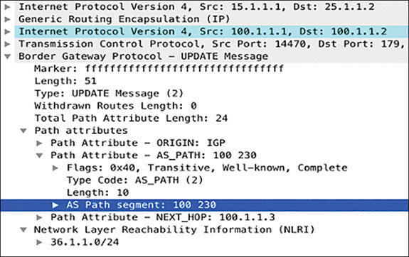
This can be handled in two ways:
Configure allowas-in on the spokes R2 and R3.
Send a default route from the hub R1 to R2 and R3.
The allowas-in feature disables the loop prevention in BGP. With this featured configured, a BGP speaking router no longer denies any BGP updates that have its own ASN listed. It is applied on a per-neighbor basis with the neighbor command. On configuring the feature on the spokes R2 and R3, the debugging outputs show that they now install each other’s host network. The show ip bgp output confirms this:
On R2:
R2(config)#router bgp 230
R2(config-router)#neighbor 100.1.1.1 allowas-in
You should see the following debug output:
BGP(0): Revise route installing 1 of 1 routes for 36.1.1.0/24 ->
100.1.1.3(global) to main IP table

R2#show ip bgp | begin Net

     Network          Next Hop           Metric LocPrf Weight Path
 *>   17.1.1.0/24      100.1.1.1               0             0 100 i
 *>   24.1.1.0/24      0.0.0.0                 0         32768 i
 *>   36.1.1.0/24      100.1.1.3                             0 100 230 i
On R3:
R3(config)#router bgp 230
R3(config-router)#neighbor 100.1.1.1 allowas-in

BGP(0): Revise route installing 1 of 1 routes for 24.1.1.0/24 ->
100.1.1.2(global) to main IP table

R3#show ip bgp | begin Net

     Network          Next Hop           Metric LocPrf Weight Path
 *>   17.1.1.0/24      100.1.1.1           0             0 100 i
 *>   24.1.1.0/24      100.1.1.2                             0 100 230 i
 *>   36.1.1.0/24      0.0.0.0             0            32768 i
The design requires the hub to send down a default route. So, much as in the iBGP section, the following configuration causes R1 to propagate a default route to the spokes R2 and R3 while suppressing the more specific prefixes. The next hop IP address of the default route is the hub R1’s tunnel IP address 100.1.1.1:
On R1:
The following prefix-list and route-map are likely already configured from an earlier step.
R1(config)#ip prefix-list TST seq 5 permit 0.0.0.0/0

R1(config)#route-map default permit 10
R1(config-route-map)#match ip address prefix TST

R1(config)#router bgp 100
R1(config-router)#address-family ipv4
R1(config-router-af)#neighbor spokes default-originate
R1(config-router-af)#neighbor spokes route-map default out

R1#clear ip bgp * out
On R2:
R2#show ip bgp | begin Net

     Network          Next Hop            Metric LocPrf Weight Path
 *>   0.0.0.0          100.1.1.1                              0 100 i
 *>   24.1.1.0/24      0.0.0.0                  0         32768 i
On R3:
R3#show ip bgp | begin Net

     Network          Next Hop            Metric LocPrf Weight Path
 *>   0.0.0.0          100.1.1.1                              0 100 i
 *>   36.1.1.0/24      0.0.0.0                  0         32768 i
As in the other sections, traceroutes between the sites verify proper reachability for both configuration scenarios.
On R4:
R4#traceroute 17.1.1.7 probe 1
Type escape sequence to abort.

Tracing the route to 17.1.1.7
VRF info: (vrf in name/id, vrf out name/id)
  1 24.1.1.2 6 msec
  2 100.1.1.1 8 msec
  3 17.1.1.7 13 msec
On R6:
R6#traceroute 17.1.1.7 probe 1
Type escape sequence to abort.

Tracing the route to 17.1.1.7
VRF info: (vrf in name/id, vrf out name/id)
  1 36.1.1.3 5 msec
  2 100.1.1.1 11 msec
  3 17.1.1.7 12 msec

R4#traceroute 36.1.1.6 probe 1

Type escape sequence to abort.
Tracing the route to 36.1.1.6
VRF info: (vrf in name/id, vrf out name/id)
  1 24.1.1.2 9 msec
  2 100.1.1.1 11 msec
  3 100.1.1.3 42 msec
  4 36.1.1.6 12 msec
Implement Phase 2
Design Goal
When the VPN was first deployed, traffic patterns were mostly between remote sites and the main campus site. Over the years, the network engineers at ABC Corp have noticed the traffic patterns shift to be primarily remote site to remote site. To reduce the load on the main site hub router, the network engineers have decided to extend the network to allow the remote sites to directly communicate with each other.
DMVPN Tunnel Configuration
Before beginning configuration, the routing protocol and DMVPN tunnel interfaces are removed and rebuilt on each router. The mGRE tunnel configuration on the hub R1 requires no modifications from the configurations made in Phase 1:
On All Routers
Rx(config)#no interface tunnel 100
On R1:
R1(config)#no router bgp 100
On R1:
R1(config)#interface tunnel 100
R1(config-if)#ip address 100.1.1.1 255.255.255.0
R1(config-if)#ip nhrp map multicast dynamic
R1(config-if)#ip nhrp network-id 100
R1(config-if)#tunnel source GigabitEthernet0/5
R1(config-if)#tunnel mode gre multipoint
As mentioned in the introduction section, for DMVPN Phase 2 operation, the spokes must be configured with multipoint GRE tunnels, just like the hub, to allow dynamic tunnels to form between them. With such a configuration, in order for the spokes to register with the hub properly, the spokes must be configured with static NHRP mapping information for the hub, along with appropriate static NHRP multicast mapping information if dynamic routing protocols that use multicast are used.
To configure the static mapping, the ip nhrp nhs 100.1.1.1 nbma 15.1.1.1 multicast command is configured on the tunnel interfaces on R2 and R3, along with the tunnel mode gre multipoint command to convert the point-to-point GRE tunnel into an mGRE tunnel. These two commands configure the appropriate static NHRP and NHRP multicast mappings on the spoke routers:
On R2:
R2#undebug all
All possible debugging has been turned off

R2(config)#no router bgp 230


R2(config)#interface tunnel 100
R2(config-if)#ip address 100.1.1.2 255.255.255.0
R2(config-if)#ip nhrp network-id 100
R2(config-if)#tunnel source 25.1.1.2
R2(config-if)#tunnel mode gre multipoint
R2(config-if)#ip nhrp nhs 100.1.1.1 nbma 15.1.1.1 multicast
On R3:
R3#undebug all
All possible debugging has been turned off

R3(config)#no router bgp 230

R3(config)#interface tunnel 100
R3(config-if)#ip address 100.1.1.3 255.255.255.0
R3(config-if)#ip nhrp network-id 100
R3(config-if)#tunnel source 35.1.1.3
R3(config-if)#tunnel mode gre multipoint
R3(config-if)#ip nhrp nhs 100.1.1.1 nbma 15.1.1.1 multicast
The show dmvpn output verifies the tunnels between the Hub and Spokes. Notice the “D” flag on R1 for each Spoke and the “S” flag on R2 and R3 for the Hub. The “D” flag signifies the mapping information was dynamically learned. This is because the Hub learns of the Spokes via NHRP registration messages sent to it by the spokes directly. The “S” flag on the spokes signifies the mapping information was learned statically, because the spokes have been statically configured with Hub’s NBMA-to-tunnel-IP mapping:
On R1:
R1#show dmvpn | begin Peer NBMA

 # Ent  Peer NBMA Addr Peer Tunnel Add State  UpDn Tm Attrb
 ----- --------------- --------------- ----- -------- -----
     1 25.1.1.2              100.1.1.2    UP 00:08:29     D
     1 35.1.1.3              100.1.1.3    UP 00:09:23     D
On R2:
R2#show dmvpn | begin Peer NBMA


 # Ent  Peer NBMA Addr Peer Tunnel Add State  UpDn Tm Attrb
 ----- --------------- --------------- ----- -------- -----
     1 15.1.1.1              100.1.1.1    UP 00:06:56     S
On R3:
R3#show dmvpn | begin Peer NBMA

 # Ent  Peer NBMA Addr Peer Tunnel Add State  UpDn Tm Attrb
 ----- --------------- --------------- ----- -------- -----
     1 15.1.1.1              100.1.1.1    UP 00:03:42     S
The show ip nhrp multicast command on R1, R2, and R3 checks for multicast connectivity and replication. The hub automatically assigns a multicast flag to every spoke that registers with it—hence the flag dynamic. The spokes are manually told to send multicast to the configured NHS IP address—hence the flag nhs.
On R1:
R1#show ip nhrp multicast

  I/F     NBMA address
Tunnel100  35.1.1.3        Flags: dynamic          (Enabled)
Tunnel100  25.1.1.2        Flags: dynamic          (Enabled)
On R2:
R2#show ip nhrp multicast

  I/F     NBMA address
Tunnel100  15.1.1.1        Flags: nhs              (Enabled)
On R3:
R3#show ip nhrp multicast

  I/F     NBMA address
Tunnel100  15.1.1.1        Flags: nhs              (Enabled)
With DMVPN set up, a traceroute from R2 to R3’s tunnel IP address 100.1.1.3 is performed to verify reachability:
On R2:
R2#traceroute 100.1.1.3 numeric

Type escape sequence to abort.
Tracing the route to 100.1.1.3
VRF info: (vrf in name/id, vrf out name/id)
  1 100.1.1.1 [AS 100] 11 msec *  18 msec
    100.1.1.3 5 msec 5 msec 5 msec

R2#traceroute 100.1.1.3 numeric

Type escape sequence to abort.
Tracing the route to 100.1.1.3
VRF info: (vrf in name/id, vrf out name/id)
  1 100.1.1.3 [AS 100] 11 msec *  18 msec
As shown above, the first traceroute to 100.1.1.3 travels to R3 from R2 via the hub R1. The following traceroute to the same address escapes the hub and is sent directly from R2 to R3. This is an indication of spoke-to-spoke tunnel formation between R2 and R3. This is further verified with the show dmvpn output on R2 and R3. Notice the D attribute set against the R2/R3 tunnel, which indicates the dynamic nature of this spoke-to-spoke tunnel:
On R2:
R2#show dmvpn | begin Peer NBMA

 # Ent  Peer NBMA Addr Peer Tunnel Add State  UpDn Tm Attrb
 ----- --------------- --------------- ----- -------- -----
     1 15.1.1.1              100.1.1.1    UP 00:16:38     S
     1 35.1.1.3              100.1.1.3    UP 00:05:07     D
On R3:
R3#show dmvpn | begin Peer NBMA

 # Ent  Peer NBMA Addr Peer Tunnel Add State  UpDn Tm Attrb
 ----- --------------- --------------- ----- -------- -----
     1 15.1.1.1              100.1.1.1    UP 00:13:35     S
     1 25.1.1.2              100.1.1.2    UP 00:06:01     D
With DMVPN Phase 2 set up successfully between R1, R2, and R3, the next part of the task involves advertising the host networks at each site into an overlay protocol. The following section demonstrates the configuration and implementation of OSPF, EIGRP, and BGP as overlay protocols.
As mentioned in the introduction section, for DMVPN Phase 2, spoke routing tables should be populated with complete routing information for all host networks residing at remote spoke sites. This routing information should contain the original spoke’s tunnel IP address as the next hop. Applied to the scenario above, R2 should receive or calculate a route to the 36.1.1.0/24 network with R3’s tunnel interface 100.1.1.3 as the next hop. The same applies to R3. The following sections detail how to accomplish this with OSPF, EIGRP, and BGP.
Implement OSPF
The point-to-point and point-to-multipoint OSPF network types do not preserve the next hop IP addresses. Therefore, these two network types should not be used in DMVPN Phase 2. All non-broadcast network types will be ignored as their requirement of static neighbor configuration does not fit well with the DMVPN design philosophy. This leaves you with the broadcast network type for Phase 2 behavior when using OSPF as the overlay protocol.
The configuration to implement OSPF’s broadcast network type for Phase 2 behavior is similar to the configurations made in the Phase 1 section. The network type is set to broadcast with the ip ospf network broadcast command on the tunnel 100 interfaces on R1, R2, and R3. OSPF’s priority on R2 and R3 is set to 0 with the ip ospf priority 0 command to prevent them from becoming the DRs or BDRs. Finally, the respective host LAN interfaces at each site are also advertised into OSPF process 100 in Area 0. They are declared as passive interfaces under the OSPF configuration mode:
On R1:
R1(config)#no router bgp 100

R1(config)#interface tunnel 100
R1(config-if)#ip ospf network broadcast
R1(config-if)#ip ospf 100 area 0

R1(config-if)#interface g0/7
R1(config-if)#ip ospf 100 area 0

R1(config-if)#router ospf 100
R1(config-router)#passive-interface g0/7
On R2:
R2(config)#no router bgp 230

R2(config)#interface tunnel 100
R2(config-if)#ip ospf network broadcast
R2(config-if)#ip ospf 100 area 0
R2(config-if)#ip ospf priority 0

R2(config)#interface g0/4
R2(config-if)#ip ospf 100 area 0

R2(config)#router ospf 100
R2(config-router)#passive-interface g0/4
You should see the following console message:
%OSPF-5-ADJCHG: Process 100, Nbr 100.1.1.1 on Tunnel100 from LOADING
to FULL, Loading Done
On R3:
R3(config)#no router bgp 230
R3(config)#interface tunnel 100
R3(config-if)#ip ospf network broadcast
R3(config-if)#ip ospf 100 area 0
R3(config-if)#ip ospf priority 0
R3(config)#interface g0/6
R3(config-if)#ip ospf 100 area 0
R3(config)#router ospf 100
R3(config-router)#passive-interface g0/6
You should see the following console message:
%OSPF-5-ADJCHG: Process 100, Nbr 100.1.1.1 on Tunnel100 from LOADING
to FULL, Loading DoneThe show ip ospf neighbor output on R1 verifies the OSPF adjacencies between R1 and R2 and between R1 and R3:
On R1:
R1#show ip ospf neighbor Neighbor ID Pri State Dead Time Address Interface 100.1.1.2 0 FULL/DROTHER 00:00:39 100.1.1.2 Tunnel100 100.1.1.3 0 FULL/DROTHER 00:00:39 100.1.1.3 Tunnel100
The show ip route ospf output on R1, R2, and R3 verifies the remote host networks at each site:
R1#show ip route ospf | begin Gate
Gateway of last resort is not set
24.0.0.0/24 is subnetted, 1 subnets
O 24.1.1.0 [110/1001] via 100.1.1.2, 00:02:07, Tunnel100
36.0.0.0/24 is subnetted, 1 subnets
O 36.1.1.0 [110/1001] via 100.1.1.3, 00:02:07, Tunnel100
On R2:
R2#show ip route ospf | begin Gate
Gateway of last resort is not set
17.0.0.0/24 is subnetted, 1 subnets
O 17.1.1.0 [110/1001] via 100.1.1.1, 00:04:01, Tunnel100
36.0.0.0/24 is subnetted, 1 subnets
O 36.1.1.0 [110/1001] via 100.1.1.3, 00:04:01, Tunnel100
On R3:
R3#show ip route ospf | begin Gate
Gateway of last resort is not set
17.0.0.0/24 is subnetted, 1 subnets
O 17.1.1.0 [110/1001] via 100.1.1.1, 00:02:26, Tunnel100
24.0.0.0/24 is subnetted, 1 subnets
O 24.1.1.0 [110/1001] via 100.1.1.2, 00:02:26, Tunnel100
Notice that the next hops on R2 and R3 for each other’s host network point to each other’s tunnel IP address. Next, traceroute is performed twice from R4 to R6. The first traceroute traverses the hub R1. Once the resolution process concludes, the next traceroute bypasses the hub, and traffic is sent over the dynamic spoke-to-spoke tunnel between R2 and R3:
On R4:
R4#traceroute 36.1.1.6 Type escape sequence to abort. Tracing the route to 36.1.1.6 VRF info: (vrf in name/id, vrf out name/id) 1 24.1.1.2 4 msec 5 msec 5 msec 2 100.1.1.1 3 msec 2 msec 1 msec 3 100.1.1.3 1 msec 0 msec 1 msec 4 36.1.1.6 0 msec 2 msec 1 msec R4#traceroute 36.1.1.6 Type escape sequence to abort. Tracing the route to 36.1.1.6 VRF info: (vrf in name/id, vrf out name/id) 1 24.1.1.2 1 msec 4 msec 6 msec 2 100.1.1.3 1 msec 1 msec 0 msec 3 36.1.1.6 1 msec 1 msec 0 msec
The second traceroute shows the traffic from R4 to R7 being routed through the hub:
On R4:
R4#traceroute 17.1.1.7 probe 1 Type escape sequence to abort. Tracing the route to 17.1.1.7 VRF info: (vrf in name/id, vrf out name/id) 1 24.1.1.2 11 msec 2 100.1.1.1 10 msec 3 17.1.1.7 12 msec
Implement EIGRP
The EIGRP configuration to implement Phase 2 is simple. EIGRP is enabled on the tunnel interface 100 on R1, R2, and R3 with the network command under the EIGRP router configuration mode. Respective host networks at each site are then advertised into EIGRP using the same command. These interfaces are then declared as passive to prevent any neighborships from forming over them.
Two additional EIGRP commands are necessary on the hub R1 for Phase 2 behavior to occur. The no ip split-horizon eigrp 100 command on R1’s tunnel 100 disables split horizon to ensure that R1 advertises specific host networks from R2 to R3 and from R3 to R2. In addition, the no ip next-hop-self eigrp 100 command prevents R1 from setting itself as the next hop for the advertised prefixes. Before you do all the configurations, you must remove OSPF from the earlier section:
On R1:
R1(config)#no router ospf 100 R1(config)#interface tunnel 100 R1(config-if)#no ip ospf network broadcast R1(config)#router eigrp 100 R1(config-router)#network 17.1.1.1 0.0.0.0 R1(config-router)#network 100.1.1.1 0.0.0.0 R1(config-router)#passive-interface g0/7 R1(config)#interface tunnel 100 R1(config-if)#no ip next-hop-self eigrp 100 R1(config-if)#no ip split-horizon eigrp 100
On R2:
R2(config)#no router ospf 100 R2(config)#interface tunnel 100 R2(config-if)#no ip ospf network broadcast R2(config-if)#no ip ospf priority 0 R2(config)#router eigrp 100 R2(config-router)#network 24.1.1.2 0.0.0.0 R2(config-router)#network 100.1.1.2 0.0.0.0 R2(config-router)#passive-interface g0/4
You should see the following console message:
%DUAL-5-NBRCHANGE: EIGRP-IPv4 100: Neighbor 100.1.1.1 (Tunnel100) is
up: new adjacencyOn R3:
R3(config)#no router ospf 100 R3(config)#interface tunnel 100 R3(config-if)#no ip ospf network broadcast R3(config-if)#no ip ospf priority 0 R3(config)#router eigrp 100 R3(config-router)#network 36.1.1.3 0.0.0.0 R3(config-router)#network 100.1.1.3 0.0.0.0 R3(config-router)#passive-interface g0/6
You should see the following console message:
%DUAL-5-NBRCHANGE: EIGRP-IPv4 100: Neighbor 100.1.1.1 (Tunnel100) is
up: new adjacencyThe show ip eigrp 100 neighbors command on R1 verifies the EIGRP neighborships between R1 and R2 and between R1 and R3:
On R1:
R1#show ip eigrp 100 neighbors
EIGRP-IPv4 Neighbors for AS(100)
H Address Interface Hold Uptime SRTT RTO
Q Seq
(sec) (ms)
Cnt Num
1 100.1.1.3 Tu100 14 00:02:24 4 1470
0 3
0 100.1.1.2 Tu100 11 00:06:22 2 1470
0 4
The show ip route eigrp 100 command shows the EIGRP learned routes on R1, R2, and R3. Much as with OSPF for Phase 2, notice that the next hops for 24.1.1.0/24 and 36.1.1.0/24 on R2 and R3 point to each other’s tunnel IP address:
On R1:
R1#show ip route eigrp 100 | begin Gate
Gateway of last resort is not set
24.0.0.0/24 is subnetted, 1 subnets
D 24.1.1.0 [90/26880256] via 100.1.1.2, 00:09:02, Tunnel100
36.0.0.0/24 is subnetted, 1 subnets
D 36.1.1.0 [90/26880256] via 100.1.1.3, 00:05:04, Tunnel100
On R2:
R2#show ip route eigrp 100 | begin Gate
Gateway of last resort is not set
17.0.0.0/24 is subnetted, 1 subnets
D 17.1.1.0 [90/26880256] via 100.1.1.1, 00:09:52, Tunnel100
36.0.0.0/24 is subnetted, 1 subnets
D 36.1.1.0 [90/28160256] via 100.1.1.3, 00:05:55, Tunnel100
On R3:
R3#show ip route eigrp 100 | begin Gate
Gateway of last resort is not set
17.0.0.0/24 is subnetted, 1 subnets
D 17.1.1.0 [90/26880256] via 100.1.1.1, 00:06:25, Tunnel100
24.0.0.0/24 is subnetted, 1 subnets
D 24.1.1.0 [90/28160256] via 100.1.1.2, 00:06:25, Tunnel100
The first traceroute from R4 to R6 traverses the hub while the NHRP resolution process completes. The following traceroute follows the direct path over the spoke-to-spoke tunnel between R2 and R3:
On R4:
R4#traceroute 36.1.1.3 numeric Type escape sequence to abort. Tracing the route to 36.1.1.3 VRF info: (vrf in name/id, vrf out name/id) 1 24.1.1.2 0 msec 5 msec 5 msec 2 100.1.1.1 5 msec 1 msec 0 msec 3 100.1.1.3 0 msec 1 msec 0 msec R4#traceroute 36.1.1.3 numeric Type escape sequence to abort. Tracing the route to 36.1.1.3 VRF info: (vrf in name/id, vrf out name/id) 1 24.1.1.2 1 msec 5 msec 5 msec 2 100.1.1.3 1 msec 1 msec 0 msec
A traceroute from R4 to R7 at the main site is routed through the hub R1:
On R4:
R4#traceroute 17.1.1.7 numeric Type escape sequence to abort. Tracing the route to 18.1.1.8 VRF info: (vrf in name/id, vrf out name/id) 1 24.1.1.2 4 msec 6 msec 4 msec 2 100.1.1.1 2 msec 4 msec 1 msec 3 17.1.1.7 0 msec 1 msec 0 msec
Implement iBGP
The configuration for iBGP peering sessions is similar to the iBGP configuration made in the Phase 1 section of this chapter.
R1 is configured as a route-reflector and uses BGP’s dynamic Peering feature to allow dynamic peering sessions to be established. Spokes R2 and R3 are configured with neighbor statements to form iBGP peering sessions with R1’s tunnel IP address 100.1.1.1. The host networks at each site are advertised into BGP with the network statement. Before BGP is configured, EIGRP AS 100 must be removed:
On R1:
R1(config)#no router eigrp 100
R1(config)#router bgp 100
R1(config-router)#neighbor spokes peer-group
R1(config-router)#neighbor spokes remote-as 100
R1(config-router)#bgp listen range 100.1.1.0/24 peer-group spokes
R1(config-router)#address-family ipv4
R1(config-router-af)#neighbor spokes activate
R1(config-router-af)#neighbor spokes route-reflector-client
R1(config-router-af)#network 17.1.1.0 mask 255.255.255.0
On R2:
R2(config)#no router eigrp 100
R2(config)#router bgp 100
R2(config-router)#neighbor 100.1.1.1 remote-as 100
R2(config-router)#address-family ipv4
R2(config-router-af)#neighbor 100.1.1.1 activate
R2(config-router-af)#network 24.1.1.0 mask 255.255.255.0
You should see the following console message:
%BGP-5-ADJCHANGE: neighbor 100.1.1.1 UpOn R3:
R3(config)#no router eigrp 100
R3(config)#router bgp 100
R3(config-router)#neighbor 100.1.1.1 remote-as 100
R3(config-router)#address-family ipv4
R3(config-router-af)#network 36.1.1.0 mask 255.255.255.0
R3(config-router-af)#neighbor 100.1.1.1 activate
You should see the following console message:
%BGP-5-ADJCHANGE: neighbor 100.1.1.1 UpThe show ip bgp output on R1, R2, and R3 shows the host networks each site learns via BGP:
On R1:
R1#show ip bgp | begin Net
Network Next Hop Metric LocPrf Weight Path
*> 17.1.1.0/24 0.0.0.0 0 32768 i
*>i 24.1.1.0/24 100.1.1.2 0 100 0 i
*>i 36.1.1.0/24 100.1.1.3 0 100 0 i
On R2:
R2#show ip bgp | begin Net
Network Next Hop Metric LocPrf Weight Path
*>i 17.1.1.0/24 100.1.1.1 0 100 0 i
*> 24.1.1.0/24 0.0.0.0 0 32768 i
*>i 36.1.1.0/24 100.1.1.3 0 100 0 i
On R3:
R3#show ip bgp | begin Net
Network Next Hop Metric LocPrf Weight Path
*>i 17.1.1.0/24 100.1.1.1 0 100 0 i
*>i 24.1.1.0/24 100.1.1.2 0 100 0 i
*> 36.1.1.0/24 0.0.0.0 0 32768 i
Notice the next hop IP address for the 36.1.1.0/24 network on R2 and for the 24.1.1.0/24 network on R3 in the output above and below. Since route reflectors do not modify the next hop attribute, the next hop IP address on R2 and R3 for each other’s host networks is retained. The RIB entries on the spokes below confirm this:
On R2:
R2#show ip route bgp | begin Gate
Gateway of last resort is not set
17.0.0.0/24 is subnetted, 1 subnets
B 17.1.1.0 [200/0] via 100.1.1.1, 00:08:22
36.0.0.0/24 is subnetted, 1 subnets
B 36.1.1.0 [200/0] via 100.1.1.3, 00:04:32
On R3:
R3#show ip route bgp | begin Gate
Gateway of last resort is not set
17.0.0.0/24 is subnetted, 1 subnets
B 17.1.1.0 [200/0] via 100.1.1.1, 00:05:03
24.0.0.0/24 is subnetted, 1 subnets
B 24.1.1.0 [200/0] via 100.1.1.2, 00:05:03
To test reachability, traceroutes are performed between sites. As seen below, traffic from R4 to R6 first traverses the hub, and subsequent traffic uses the direct spoke to spoke tunnel:
On R4:
R4#traceroute 36.1.1.6 Type escape sequence to abort. Tracing the route to 36.1.1.6 VRF info: (vrf in name/id, vrf out name/id) 1 24.1.1.2 4 msec 5 msec 5 msec 2 100.1.1.1 3 msec 2 msec 1 msec 3 100.1.1.3 1 msec 0 msec 1 msec 4 36.1.1.6 0 msec 2 msec 1 msec R4#traceroute 36.1.1.6 Type escape sequence to abort. Tracing the route to 36.1.1.6 VRF info: (vrf in name/id, vrf out name/id) 1 24.1.1.2 1 msec 4 msec 6 msec 2 100.1.1.3 1 msec 1 msec 0 msec 3 36.1.1.6 1 msec 1 msec 0 msec
Traffic from R4 to R7 is routed through the Hub:
On R4:
R4#traceroute 17.1.1.7 probe 1 Type escape sequence to abort. Tracing the route to 17.1.1.7 VRF info: (vrf in name/id, vrf out name/id) 1 24.1.1.2 11 msec 2 100.1.1.1 10 msec 3 17.1.1.7 12 msec
Implement eBGP
Similar to the case with the eBGP section of Phase 1, eBGP can be implemented in Phase 2 either with the Spokes in:
Same autonomous system, or
Different autonomous system
The following configures the spokes R2 and R3 in same autonomous systems, 230. Hub R1 is configured to be in AS 100. The host networks at each site are advertised into BGP with the network command.
For Phase 2, the spokes need specific routes with the true next hop IP address to trigger the NHRP resolution process. This means that, unlike with Phase 1, the hub cannot be configured to propagate a default route to the spokes, as that would reset the next hop IP address to the hub’s tunnel IP address. For this purpose, it is important to configure the allowas-in feature on R2 and R3. The allowas-in feature on the spokes R2 and R3 results in them bypassing the loop-prevention check and accepting routes with the ASN 230 in the AS_PATH attribute. Before the routers are configured, you should remove BGP from the previous task/scenario:
On R1:
R1(config)#no router bgp 100
R1(config)#router bgp 100
R1(config-router)#neighbor spokes peer-group
R1(config-router)#neighbor spokes remote-as 230
R1(config-router)#bgp listen range 100.1.1.0/24 peer-group spokes
R1(config-router)#address-family ipv4
R1(config-router-af)#neighbor spokes activate
R1(config-router-af)#network 17.1.1.0 mask 255.255.255.0
On R2:
R2(config)#no router bgp 100
R2(config)#router bgp 230
R2(config-router)#neighbor 100.1.1.1 remote-as 100
R2(config-router)#address-family ipv4
R2(config-router-af)#neighbor 100.1.1.1 activate
R2(config-router-af)#neighbor 100.1.1.1 allowas-in
R2(config-router-af)#network 24.1.1.0 mask 255.255.255.0
You should see the following console message:
%BGP-5-ADJCHANGE: neighbor 100.1.1.1 UpOn R3:
R2(config)#no router bgp 100
R3(config)#router bgp 230
R3(config-router)#neighbor 100.1.1.1 remote-as 100
R3(config-router)#address-family ipv4
R3(config-router-af)#neighbor 100.1.1.1 activate
R3(config-router-af)#neighbor 100.1.1.1 allowas-in
R3(config-router-af)#network 36.1.1.0 mask 255.255.255.0
You should see the following console message:
%BGP-5-ADJCHANGE: neighbor 100.1.1.1 UpThe show ip bgp output verifies that R1, R2, and R3 learn of each other’s host networks via BGP:
On R1:
R1#show ip bgp | begin Net
Network Next Hop Metric LocPrf Weight Path
*> 17.1.1.0/24 0.0.0.0 0 32768 i
*> 24.1.1.0/24 100.1.1.2 0 0 230 i
*> 36.1.1.0/24 100.1.1.3 0 0 230 i
On R2:
R2#show ip bgp | begin Net
Network Next Hop Metric LocPrf Weight Path
*> 17.1.1.0/24 100.1.1.1 0 0 100 i
*> 24.1.1.0/24 0.0.0.0 0 32768 i
*> 36.1.1.0/24 100.1.1.3 0 100 230 i
On R3:
R3#show ip bgp | begin Net
Network Next Hop Metric LocPrf Weight Path
*> 17.1.1.0/24 100.1.1.1 0 0 100 i
*> 24.1.1.0/24 100.1.1.2 0 100 230 i
*> 36.1.1.0/24 0.0.0.0 0 32768 i
The above demonstrated the configuration commands needed to establish eBGP peering between the hub and spokes with the spokes sharing the same ASN. The following implements the second design option, where the spokes R2 and R3 are placed in different autonomous systems—ASN 200 and AS 300, respectively. They are configured to form eBGP peerings with the hub R1 in ASN 100. The host networks are advertised into BGP with the network command:
On R1:
R1(config)#router bgp 100
R1(config-router)#no neighbor spokes remote-as 230
R1(config-router)#neighbor spokes remote-as 200 alternate-as 300
On R2:
R2(config)#no router bgp 230
R2(config)#router bgp 200
R2(config-router)#neighbor 100.1.1.1 remote-as 100
R2(config-router)#address-family ipv4
R2(config-router-af)#network 24.1.1.0 mask 255.255.255.0
R2(config-router-af)#neighbor 100.1.1.1 activate
You should see the following console message:
%BGP-5-ADJCHANGE: neighbor 100.1.1.1 UpOn R3:
R3(config)#no router bgp 230
R3(config)#router bgp 300
R3(config-router)#neighbor 100.1.1.1 remote-as 100
R3(config-router)#address-family ipv4
R3(config-router-af)#neighbor 100.1.1.1 activate
R3(config-router-af)#network 36.1.1.0 mask 255.255.255.0
You should see the following console message:
%BGP-5-ADJCHANGE: neighbor 100.1.1.1 UpThe show ip bgp output on R1, R2, and R3 confirms the host networks learned via BGP. The next hop IP address for 36.1.1.0/24 is R3’s tunnel IP address 100.1.1.3 on R2. Similarly, the next hop IP address for the 24.1.1.0/24 network is R2’s tunnel IP address 100.1.1.2 on R3. This is a result of BGP third-party next hop feature, which is turned on by default:
On R1:
R1#show ip bgp | begin Net
Network Next Hop Metric LocPrf Weight Path
*> 17.1.1.0/24 0.0.0.0 0 32768 i
*> 24.1.1.0/24 100.1.1.2 0 0 200 i
*> 36.1.1.0/24 100.1.1.3 0 0 300 i
On R2:
R2#show ip bgp | begin Net
Network Next Hop Metric LocPrf Weight Path
*> 17.1.1.0/24 100.1.1.1 0 0 100 i
*> 24.1.1.0/24 0.0.0.0 0 32768 i
*> 36.1.1.0/24 100.1.1.3 0 100 300 i
On R3:
R3#show ip bgp | begin Net
Network Next Hop Metric LocPrf Weight Path
*> 17.1.1.0/24 100.1.1.1 0 0 100 i
*> 24.1.1.0/24 100.1.1.2 0 100
200 i
*> 36.1.1.0/24 0.0.0.0 0 32768 i
To test reachability for both scenarios, traceroutes are performed between sites. As seen below, traffic from R4 to R6 first traverses the hub and subsequent traffic uses the direct spoke to spoke tunnel:
On R4:
R4#traceroute 36.1.1.6 Type escape sequence to abort. Tracing the route to 36.1.1.6 VRF info: (vrf in name/id, vrf out name/id) 1 24.1.1.2 4 msec 5 msec 5 msec 2 100.1.1.1 3 msec 2 msec 1 msec ! DMVPN Hub R1 3 100.1.1.3 1 msec 0 msec 1 msec 4 36.1.1.6 0 msec 2 msec 1 msec R4#traceroute 36.1.1.6 Type escape sequence to abort. Tracing the route to 36.1.1.6 VRF info: (vrf in name/id, vrf out name/id) 1 24.1.1.2 1 msec 4 msec 6 msec 2 100.1.1.3 1 msec 1 msec 0 msec 3 36.1.1.6 1 msec 1 msec 0 msec
Traffic from R4 to R7 is routed through the Hub:
On R4:
R4#traceroute 17.1.1.7 probe 1 Type escape sequence to abort. Tracing the route to 17.1.1.7 VRF info: (vrf in name/id, vrf out name/id) 1 24.1.1.2 11 msec 2 100.1.1.1 10 msec 3 17.1.1.7 12 msec
Implement Phase 3
Design Goal
During a network design review, the network engineers at ABC Corp evaluate the effect of routing protocol updates and size on the remote site spoke routers as ABC Corp expanded into other locations. They decide that it was not necessary for the remote sites to initially receive all routing information for all other remote sites unless those sites need to directly communicate. The engineering team decides to implement complete summarization from the main site hub router toward the remote site spoke routers while retaining the ability for remote sites to directly communicate with each other.
DMVPN Tunnel Configuration
To enable Phase 3 enhancements for the DMVPN cloud, the ip nhrp redirect command is added to the Phase 2 DMVPN tunnel configuration on the hub, as indicated in the introductory sections. Likewise, the ip nhrp shortcut command is added to the Phase 2 DMVPN tunnel configuration on the spokes R2 and R3. These changes are shown below by first removing the current tunnel 100 interfaces on R1, R2, and R3. The tunnel 100 interface is then recreated with the Phase 3 enhancement configuration commands:
On R1:
R1(config)#no interface tunnel 100
R1(config)#interface tunnel 100
R1(config-if)#ip address 100.1.1.1 255.255.255.0
R1(config-if)#tunnel source 15.1.1.1
R1(config-if)#tunnel mode gre multipoint
R1(config-if)#ip nhrp redirect
R1(config-if)#ip nhrp network-id 100
R1(config-if)#ip nhrp map multicast dynamic
On R2:
R2(config)#no interface tunnel 100
R2(config)#interface tunnel 100
R2(config-if)#ip address 100.1.1.2 255.255.255.0
R2(config-if)#ip nhrp network-id 100
R2(config-if)#tunnel source 25.1.1.2
R2(config-if)#tunnel mode gre multipoint
R2(config-if)#ip nhrp nhs 100.1.1.1 nbma 15.1.1.1 multicast
R2(config-if)#ip nhrp shortcut
On R3:
R3(config)#no interface tunnel 100
R3(config)#interface tunnel 100
R3(config-if)#ip address 100.1.1.3 255.255.255.0
R3(config-if)#ip nhrp network-id 100
R3(config-if)#tunnel source 35.1.1.3
R3(config-if)#tunnel mode gre multipoint
R3(config-if)#ip nhrp nhs 100.1.1.1 nbma 15.1.1.1 multicast
R3(config-if)#ip nhrp shortcut
To verify the configuration:
The show ip nhrp command is then issued on R1. As seen below, both R2 and R3 have successful registered with the hub:
On R1:
R1#show ip nhrp 100.1.1.2/32 via 100.1.1.2 Tunnel100 created 00:03:56, expire 00:08:33 Type: dynamic, Flags: registered nhop NBMA address: 25.1.1.2 100.1.1.3/32 via 100.1.1.3 Tunnel100 created 00:03:57, expire 00:09:08 Type: dynamic, Flags: registered nhop NBMA address: 35.1.1.3
Implement OSPF
Because it is not possible to completely summarize routing information from hub to spokes in OSPF, OSPF is not suitable for the design goals of this section. As such, OSPF will not be implemented in this section.
Note
It is important to understand that, as long as the spokes are configured with mGRE interfaces, OSPF’s broadcast network type can be used to build direct spoke-to-spoke tunnels. However, this configuration does not necessarily result in true Phase 3 behavior. Due to the next hop being preserved with the use of the broadcast network type, the RIB and CEF entries point to the true next hop: the remote spoke. As a result, the spokes self-trigger a resolution request for the next hop.
In true Phase 3 behavior, the NHRP resolution process should be triggered because of receiving the traffic indication messages from the hub.
In actuality, the spoke will perform two resolutions: one for the remote spoke’s overlay address (caused by an incomplete CEF adjacency, a Phase 2 construct) and another for the target network (caused by the NHRP traffic indication message it receives from the hub).
Due to this order of operations, the Phase 3 resolution is redundant and may lead to no change in the routing table (depending on how specific the prefixes are).
The fact that the Phase 3 resolution is redundant and can result in no change leads to the conclusion that OSPF’s broadcast network and the NBMA network types do not allow for true Phase 3 behavior. At the very best, the Phase 3 enhancements are superfluous if used because the next hop is already pointing to the correct remote spoke.
This leaves point-to-point and point-to-multipoint OSPF network types. These network types can be implemented to achieve true, efficient Phase 3 behavior. The hub R1 is configured with a point-to-multipoint network type as it must be form OSPF adjacencies with both R2 and R3. Spokes R2 and R3 use the point-to-point OSPF network type on their tunnel interfaces to allow them to form OSPF adjacencies with R1. The hello timer on the hub is modified to 10 seconds to match the hello timer of point-to-point interface on the spokes.
Even though the above P2P/P2MP configuration allows for Phase 3 resolution to be implemented properly without redundant Phase 2-style resolution, OSPF cannot take advantage of a fully optimized Phase 3 implementation where minimal routing information is shared between the hub and spokes. This is because of OSPF’s limitations with summarization within an single OSPF area. R1, R2, and R3 in the same area must have complete topology information in order to maintain loop-free SPF computations in OSPF. Thus, R1 cannot simply flood a default route and suppress other more-specific routing information from the spokes.
Implement EIGRP
Implementing full Phase 3 DMVPN designs with summarization from the hub to the spokes is not fully possible with OSPF. This is because OSPF has strict topology and hierarchy rules for it to operate. EIGRP, on the other hand, has no such topological or hierarchical constraints. Thus, it can easily accommodate Phase 3 summarization.
The following enables EIGRP on the tunnel 100 and the host network interfaces on R1, R2, and R3. The passive-interface command declares the host-facing interfaces passive, preventing any EIGRP adjacencies from forming over them. Before EIGRP is configured, BGP must be removed from the previous task:
On R1:
R1(config)#no router bgp 100
R1(config)#router eigrp 100
R1(config-router)#network 17.1.1.1 0.0.0.0
R1(config-router)#network 100.1.1.1 0.0.0.0
R1(config-router)#passive-interface g0/7
On R2:
R2(config)#no router bgp 200
R2(config)#router eigrp 100
R2(config-router)#network 24.1.1.2 0.0.0.0
R2(config-router)#network 100.1.1.2 0.0.0.0
R2(config-router)#passive-interface g0/4
You should see the following console message:
%DUAL-5-NBRCHANGE: EIGRP-IPv4 100: Neighbor 100.1.1.1 (Tunnel100) is
up: new adjacencyOn R3:
R3(config)#no router bgp 300
R3(config)#router eigrp 100
R3(config-router)#network 36.1.1.3 0.0.0.0
R3(config-router)#network 100.1.1.3 0.0.0.0
R3(config-router)#passive-interface g0/6
You should see the following console message:
%DUAL-5-NBRCHANGE: EIGRP-IPv4 100: Neighbor 100.1.1.1 (Tunnel100) is
up: new adjacencyAfter completing the above, the following verifies the EIGRP neighborships between R1 - R2 and R1 - R3. The routing tables on each of these routers also show the host networks at each site learned via EIGRP:
On R1:
R1#show ip eigrp 100 neighbors
EIGRP-IPv4 Neighbors for AS(100)
H Address Interface Hold Uptime SRTT RTO Q Seq
(sec) (ms) Cnt
Num
1 100.1.1.3 Tu100 14 00:02:30 12 1470 0 3
0 100.1.1.2 Tu100 11 00:05:59 5 1470 0 3
On R1:
R1#show ip route eigrp 100 | begin Gate
Gateway of last resort is not set
24.0.0.0/24 is subnetted, 1 subnets
D 24.1.1.0 [90/26880256] via 100.1.1.2, 00:08:52, Tunnel100
36.0.0.0/24 is subnetted, 1 subnets
D 36.1.1.0 [90/26880256] via 100.1.1.3, 00:05:22, Tunnel100
On R2:
R2#show ip route eigrp 100 | begin Gate
Gateway of last resort is not set
17.0.0.0/24 is subnetted, 1 subnets
D 17.1.1.0 [90/26880256] via 100.1.1.1, 00:09:50, Tunnel100
On R3:
R3#show ip route eigrp 100 | begin Gate
Gateway of last resort is not set
17.0.0.0/24 is subnetted, 1 subnets
D 17.1.1.0 [90/26880256] via 100.1.1.1, 00:07:05, Tunnel100
On R3:
R3#show ip route eigrp 100 | begin Gate
Gateway of last resort is not set
17.0.0.0/24 is subnetted, 1 subnets
D 17.1.1.0 [90/26880256] via 100.1.1.1, 00:07:05, Tunnel100
In the routing table above, notice that the hub has learned of the host networks 24.1.1.0/24 and 36.1.1.0/24 via EIGRP from R2 and R3, respectively. R2 and R3, however, only learn of the host network 17.1.1.0/24 at the main site. The reason for this, as already mentioned, is that the advertisement of the host networks at the remote sites is being prevented by split horizon on the hub R1. However, as per the design requirements, the spokes R2 and R3 do not need the specific routes; rather, the route information should be summarized by the hub. For this purpose, there is no need to disable split horizon at the hub site.
To complete the design, R1 is configured to send a default route via EIGRP to R2 and R3 with the ip summary-address eigrp 100 0.0.0.0 0.0.0.0 command in its tunnel 100 interface:
On R1:
R1(config)#interface tunnel 100 R1(config-if)#ip summary-address eigrp 100 0.0.0.0 0.0.0.0
Following reveals the routing table on R2 and R3 that is now populated with an EIGRP default route from the hub R1:
On R2:
R2#show ip route eigrp 100 | begin Gate Gateway of last resort is 100.1.1.1 to network 0.0.0.0 D* 0.0.0.0/0 [90/26880256] via 100.1.1.1, 00:01:22, Tunnel100
On R3:
R3#show ip route eigrp 100 | begin Gate Gateway of last resort is 100.1.1.1 to network 0.0.0.0 D* 0.0.0.0/0 [90/26880256] via 100.1.1.1, 00:01:49, Tunnel100
Traceroutes are then issued to test reachability between the sites. As seen below, traffic from R4 to R6 first traverses the hub. Once the NHRP resolution process completes, the same traffic is shown to travel over the spoke to spoke tunnel between R2 and R3. Traffic from R4 to R7 is sent to the hub:
On R4:
R4#traceroute 36.1.1.6 Type escape sequence to abort. Tracing the route to 36.1.1.6 VRF info: (vrf in name/id, vrf out name/id) 1 24.1.1.2 4 msec 5 msec 5 msec 2 100.1.1.1 3 msec 2 msec 1 msec ! DMVPN Hub R1 3 100.1.1.3 1 msec 0 msec 1 msec 4 36.1.1.6 0 msec 2 msec 1 msec R4#traceroute 36.1.1.6 Type escape sequence to abort. Tracing the route to 36.1.1.6 VRF info: (vrf in name/id, vrf out name/id) 1 24.1.1.2 1 msec 4 msec 6 msec 2 100.1.1.3 1 msec 1 msec 0 msec 3 36.1.1.6 1 msec 1 msec 0 msec
Traffic from R4 to R7 is routed through the Hub:
On R4:
R4#traceroute 17.1.1.7 probe 1 Type escape sequence to abort. Tracing the route to 17.1.1.7 VRF info: (vrf in name/id, vrf out name/id) 1 24.1.1.2 11 msec 2 100.1.1.1 10 msec ! DMVPN Hub R1 3 17.1.1.7 12 msec
The show ip route nhrp | begin Gate command proves that R2 and R3 have added more-specific NHRP routes to reach each other’s remote networks:
On R2:
R2#show ip route nhrp | begin Gate
Gateway of last resort is 100.1.1.1 to network 0.0.0.0
36.0.0.0/24 is subnetted, 1 subnets
H 36.1.1.0 [250/1] via 100.1.1.3, 00:00:27, Tunnel100
100.0.0.0/8 is variably subnetted, 3 subnets, 2 masks
H 100.1.1.3/32 is directly connected, 00:00:27, Tunnel100
On R3:
R3#show ip route nhrp | begin Gate
Gateway of last resort is 100.1.1.1 to network 0.0.0.0
24.0.0.0/24 is subnetted, 1 subnets
H 24.1.1.0 [250/1] via 100.1.1.2, 00:00:44, Tunnel100
100.0.0.0/8 is variably subnetted, 3 subnets, 2 masks
H 100.1.1.2/32 is directly connected, 00:00:44, Tunnel100
Implement iBGP
Just as with EIGRP, BGP has no topological or hierarchical constraints, allowing full Phase 3 summarization to be used. To implement this design, R1 is once again configured to function as a route reflector and is configured for dynamic iBGP peerings with clients R2 and R3. The host networks at each site are advertised into BGP with the network statement. Before BGP is configured, the EIGRP routing protocol must be removed and the NHRP cache should be cleared on R2 and R3:
On R1:
R1(config)#no router eigrp 100
R1(config)#router bgp 100
R1(config-router)#neighbor spokes peer-group
R1(config-router)#neighor spokes remote 100
R1(config-router)#bgp listen range 100.1.1.0/24 peer-group spokes
R1(config-router)#address-family ipv4
R1(config-router-af)#neighor spokes activate
R1(config-router-af)#network 17.1.1.0 mask 255.255.255.0
On R2:
R2(config)#no router eigrp 100
R2(config)#router bgp 100
R2(config-router)#neighbor 100.1.1.1 remote-as 100
R2(config-router)#address-family ipv4
R2(config-router-af)#network 24.1.1.0 mask 255.255.255.0
R2(config-router-af)#neighbor 100.1.1.1 activate
R2#clear ip nhrp
You should see the following console message:
%BGP-5-ADJCHANGE: neighbor 100.1.1.1 UpOn R3:
R3(config)#no router eigrp 100
R3#clear ip nhrp
R3(config)#router bgp 100
R3(config-router)#neighbor 100.1.1.1 remote-as 100
R3(config-router)#address-family ipv4
R3(config-router-af)#network 36.1.1.0 mask 255.255.255.0
R3(config-router-af)#neighbor 100.1.1.1 activate
You should see the following console message:
%BGP-5-ADJCHANGE: neighbor 100.1.1.1 UpR1 is configured to send a default route to the Spokes R2 and R3. The same prefix-list and route-map combination from earlier is used with the neighbor statement on R1. This ensures that R1 only advertises the default route while suppressing the more specific networks 24.1.1.0/24 and 36.1.1.0/24:
On R1:
R1(config)#ip prefix-list TST permit 0.0.0.0/0 R1(config)#route-map default permit 10 R1(config-route-map)#match ip address prefix TST R1(config)#router bgp 100 R1(config-router)#address-family ipv4 R1(config-router-af)#neighbor spokes default-originate R1(config-router-af)#neighbor spokes route-map default out R1#clear ip bgp * out
On completing the above configurations, the routing and BGP tables look as shown below. Notice that the next hop IP address for the default route on R2 and R3 is R1’s tunnel IP address, 100.1.1.1.
R1#show ip bgp | begin Net
Network Next Hop Metric LocPrf Weight Path
0.0.0.0 0.0.0.0 0 i
*> 17.1.1.0/24 0.0.0.0 0 32768 i
*>i 24.1.1.0/24 100.1.1.2 0 100 0 i
*>i 36.1.1.0/24 100.1.1.3 0 100 0 i
R1#show ip route bgp | begin Gate
Gateway of last resort is not set
24.0.0.0/24 is subnetted, 1 subnets
B 24.1.1.0 [200/0] via 100.1.1.2, 00:09:51
36.0.0.0/24 is subnetted, 1 subnets
B 36.1.1.0 [200/0] via 100.1.1.3, 00:06:31
On R2:
R2#show ip bgp | begin Net
Network Next Hop Metric LocPrf Weight Path
*>i 0.0.0.0 100.1.1.1 0 100 0 i
*> 24.1.1.0/24 0.0.0.0 0 32768 i
R2#show ip route bgp | begin Gate
Gateway of last resort is 100.1.1.1 to network 0.0.0.0
B* 0.0.0.0/0 [200/0] via 100.1.1.1, 00:01:34
On R3:
R3#show ip bgp | begin Net
Network Next Hop Metric LocPrf Weight Path
*>i 0.0.0.0 100.1.1.1 0 100 0 i
*> 36.1.1.0/24 0.0.0.0 0 32768 i
R3#show ip route bgp | begin Gate
Gateway of last resort is 100.1.1.1 to network 0.0.0.0
B* 0.0.0.0/0 [200/0] via 100.1.1.1, 00:02:32
Traceroutes are then issued to test reachability between the sites. As seen below, traffic from R4 to R6 at 2 first traverses the hub. Once the NHRP resolution process completes, the same traffic is shown to travel over the spoke to spoke tunnel between R2 and R3. Traffic from R4 to R7 is sent to the hub:
On R4:
R4#traceroute 36.1.1.6 Type escape sequence to abort. Tracing the route to 36.1.1.6 VRF info: (vrf in name/id, vrf out name/id) 1 24.1.1.2 4 msec 5 msec 5 msec 2 100.1.1.1 3 msec 2 msec 1 msec 3 100.1.1.3 1 msec 0 msec 1 msec 4 36.1.1.6 0 msec 2 msec 1 msec R4#traceroute 36.1.1.6 Type escape sequence to abort. Tracing the route to 36.1.1.6 VRF info: (vrf in name/id, vrf out name/id) 1 24.1.1.2 1 msec 4 msec 6 msec 2 100.1.1.3 1 msec 1 msec 0 msec 3 36.1.1.6 1 msec 1 msec 0 msec
Traffic from R4 to R7 is routed through the Hub:
On R4:
R4#traceroute 17.1.1.7 probe 1 Type escape sequence to abort. Tracing the route to 17.1.1.7 VRF info: (vrf in name/id, vrf out name/id) 1 24.1.1.2 11 msec 2 100.1.1.1 10 msec 3 17.1.1.7 12 msec
Just as in the EIGRP example, the show ip route nhrp output from R2 and R3 below confirms the specific NHRP routes have been added to their respective routing tables for the remote networks and tunnel endpoints:
On R2:
R2#show ip route nhrp | begin Gate
Gateway of last resort is 100.1.1.1 to network 0.0.0.0
36.0.0.0/24 is subnetted, 1 subnets
H 36.1.1.0 [250/1] via 100.1.1.3, 00:00:27, Tunnel100
100.0.0.0/8 is variably subnetted, 3 subnets, 2 masks
H 100.1.1.3/32 is directly connected, 00:00:27, Tunnel100
On R3:
R3#show ip route nhrp | begin Gate
Gateway of last resort is 100.1.1.1 to network 0.0.0.0
24.0.0.0/24 is subnetted, 1 subnets
H 24.1.1.0 [250/1] via 100.1.1.2, 00:00:44, Tunnel100
100.0.0.0/8 is variably subnetted, 3 subnets, 2 masks
H 100.1.1.2/32 is directly connected, 00:00:44, Tunnel100
Implement eBGP
Similar to what was done in Phase 1 and Phase 2, eBGP can be implemented in two ways for Phase 3. The spokes can belong to the same AS or to different ASes.
Spokes in the Same AS
Below sets the base configuration for this design choice.
R1 in AS 100 will configured to form dynamic eBGP peering sessions with R2 and R3. R2 and R3 are configured in AS 230. The network statement on R1, R2, and R3 is used to advertise their respective host networks into BGP.
The allowas-in feature will not be used for Phase 3. This is because the hub R1 will be configured to send a default route to the Spokes R2 and R3. In doing so, it will set itself as the next hop IP address in compliance with the design goals.
On R1:
R1(config)#no router bgp 100
R1(config)#router bgp 100
R1(config-router)#neighbor spokes peer-group
R1(config-router)#neighbor spokes remote-as 230
R1(config-router)#bgp listen range 100.1.1.0/24 peer-group spokes
R1(config-router)#address-family ipv4
R1(config-router-af)#neighbor spokes activate
R1(config-router-af)#network 17.1.1.0 mask 255.255.255.0
On R2:
R2(config)#no router bgp 100
R2(config)#router bgp 230
R2(config-router)#neighbor 100.1.1.1 remote-as 100
R2(config-router)#address-family ipv4
R2(config-router-af)#neighbor 100.1.1.1 activate
R2(config-router-af)#network 24.1.1.0 mask 255.255.255.0
You should see the following console message:
%BGP-5-ADJCHANGE: neighbor 100.1.1.1 UpOn R3:
R3(config)#no router bgp 100
R3(config)#router bgp 230
R3(config-router)#neighbor 100.1.1.1 remote-as 100
R3(config-router)#address-family ipv4
R3(config-router-af)#neighbor 100.1.1.1 activate
R3(config-router-af)#network 36.1.1.0 mask 255.255.255.0
You should see the following console message:
%BGP-5-ADJCHANGE: neighbor 100.1.1.1 UpTo honor the design requirements, using similar methods as in earlier tasks, R1 is configured to advertise BGP default route to Spokes R2 and R3:
On R1:
R1(config)#ip prefix-list TST permit 0.0.0.0/0 R1(config)#route-map default permit 10 R1(config-route-map)#match ip address prefix-list TST R1(config)#router bgp 100 R1(config-router)#address-family ipv4 R1(config-router-af)#neighbor spokes default-originate R1(config-router-af)#neighbor spokes route-map default out R1#clear ip bgp * out
Following shows the BGP routes learned on R1, R2 and R3. Both R2 and R3 have a BGP default route from R1:
On R1:
R1#show ip bgp | begin Net
Network Next Hop Metric LocPrf Weight Path
0.0.0.0 0.0.0.0 0 i
*> 17.1.1.0/24 0.0.0.0 0 32768 i
*> 24.1.1.0/24 100.1.1.2 0 0 230 i
*> 36.1.1.0/24 100.1.1.3 0 0 230 i
R1#show ip route bgp | begin Gate
Gateway of last resort is not set
24.0.0.0/24 is subnetted, 1 subnets
B 24.1.1.0 [20/0] via 100.1.1.2, 00:08:35
36.0.0.0/24 is subnetted, 1 subnets
B 36.1.1.0 [20/0] via 100.1.1.3, 00:06:02
On R2:
R2#show ip bgp | begin Net
Network Next Hop Metric LocPrf Weight Path
*> 0.0.0.0 100.1.1.1 0 100 i
*> 24.1.1.0/24 0.0.0.0 0 32768 i
R2#show ip route bgp | begin Gate
Gateway of last resort is 100.1.1.1 to network 0.0.0.0
B* 0.0.0.0/0 [20/0] via 100.1.1.1, 00:02:44
On R3:
R3#show ip bgp | begin Net
Network Next Hop Metric LocPrf Weight Path
*> 0.0.0.0 100.1.1.1 0 100 i
*> 36.1.1.0/24 0.0.0.0 0 32768 i
R3#show ip route bgp | begin Gate
Gateway of last resort is 100.1.1.1 to network 0.0.0.0
B* 0.0.0.0/0 [20/0] via 100.1.1.1, 00:03:18
Spokes in Different Autonomous Systems
The second design option is to configure the spokes R2 and R3 in different autonomous systems—ASNs 200 and 300, respectively. The hub R1 is configured in ASN 100:
On R1:
R1(config)#router bgp 100 R1(config-router)#no neighbor spokes remote-as 230 R1(config-router)#neighbor spokes remote-as 200 alternate-as 300 R1(config-router)#address-family ipv4 R1(config-router-af)#no neighbor spokes default-originate R1(config-router-af)#no neighbor spokes route-map default out R1#clear ip bgp *
On R2:
R2(config)#no router bgp 230
R2(config)#router bgp 200
R2(config-router)#neighbor 100.1.1.1 remote-as 100
R2(config-router)#address-family ipv4
R2(config-router-af)#neighbor 100.1.1.1 activate
R2(config-router-af)#network 24.1.1.0 mask 255.255.255.0
You should see the following console message:
%BGP-5-ADJCHANGE: neighbor 100.1.1.1 UpOn R3:
R3(config)#no router bgp 230
R3(config)#router bgp 300
R3(config-router)#neighbor 100.1.1.1 remote 100
R3(config-router)#address-family ipv4
R3(config-router-af)#neighbor 100.1.1.1 act
R3(config-router-af)#network 36.1.1.0 mask 255.255.255.0
Due to the third-party next hop feature, R1 does not specify itself as the next hop when advertising paths to R2 and R3. This means that R2 and R3 see each other’s tunnel IP address as the next hop for each other’s host networks, preventing them from advertising a true Phase 3 behavior:
On R1:
R1#show ip bgp | begin Net
Network Next Hop Metric LocPrf Weight Path
*> 17.1.1.0/24 0.0.0.0 0 32768 i
*> 24.1.1.0/24 100.1.1.2 0 0 200 i
*> 36.1.1.0/24 100.1.1.3 0 0 300 i
On R2:
R2#show ip bgp | begin Net
Network Next Hop Metric LocPrf Weight Path
*> 17.1.1.0/24 100.1.1.1 0 0 100 i
*> 24.1.1.0/24 0.0.0.0 0 32768 i
*> 36.1.1.0/24 100.1.1.3 0 100 300 i
On R3:
R3#show ip bgp | begin Net
Network Next Hop Metric LocPrf Weight Path
*> 17.1.1.0/24 100.1.1.1 0 0 100 i
*> 24.1.1.0/24 100.1.1.2 0 100 200 i
*> 36.1.1.0/24 0.0.0.0 0 32768 i
This default behavior can be turned off with the neighbor spokes next-hop-self command. However, the design requires the Hub R1 to propagate a default route to R2 and R3. This means setting the next hop to self on R1 would be unnecessary as the hub would advertise itself as the next hop for the default route it generates. Because the ip prefix-list and the route-map is already configured, it should still be in R1’s running configuration; therefore, the only commands necessary on R1 to accomplish this task are to configure the neighbor spokes default-originate and neighbor spokes route-map out commands:
On R1:To see the IP prefix list and the route map:
R1#show run | include ip prefix ip prefix-list TST seq 5 permit 0.0.0.0/0 R1#show run | section route-map neighbor spokes route-map default out route-map default permit 10 match ip address prefix-list TST R1(config)#router bgp 100 R1(config-router)#address-family ipv4 R1(config-router-af)#neighbor spokes default-originate R1(config-router-af)#neighbor spokes route-map default out R1#clear ip bgp * out
As seen below, Spokes R2 and R3 have each installed a BGP default route with 100.1.1.1 as the next hop IP address:
On R2:
R2#show ip bgp | begin Net
Network Next Hop Metric LocPrf Weight Path
*> 0.0.0.0 100.1.1.1 0 100 i
*> 24.1.1.0/24 0.0.0.0 0 32768 i
On R3:
R3#show ip bgp | begin Net
Network Next Hop Metric LocPrf Weight Path
*> 0.0.0.0 100.1.1.1 0 100 i
*> 36.1.1.0/24 0.0.0.0 0 32768 i
Finally, traceroutes are issued to test reachability for both design choices. As seen below, traffic from R4 to R6 at first traverses the hub. After the NHRP resolution process completes, the same traffic is shown to travel over the spoke-to-spoke tunnel between R2 and R3. Traffic from R4 to R7 is sent to the hub:
On R4:
R4#traceroute 36.1.1.6 Type escape sequence to abort. Tracing the route to 36.1.1.6 VRF info: (vrf in name/id, vrf out name/id) 1 24.1.1.2 4 msec 5 msec 5 msec 2 100.1.1.1 3 msec 2 msec 1 msec ! DMVPN Hub R1 3 100.1.1.3 1 msec 0 msec 1 msec 4 36.1.1.6 0 msec 2 msec 1 msec R4#traceroute 36.1.1.6 Type escape sequence to abort. Tracing the route to 36.1.1.6 VRF info: (vrf in name/id, vrf out name/id) 1 24.1.1.2 1 msec 4 msec 6 msec 2 100.1.1.3 1 msec 1 msec 0 msec 3 36.1.1.6 1 msec 1 msec 0 msec
Traffic from R4 to R7 is routed through the Hub:
On R4:
R4#traceroute 17.1.1.7 probe 1 Type escape sequence to abort. Tracing the route to 17.1.1.7 VRF info: (vrf in name/id, vrf out name/id) 1 24.1.1.2 11 msec 2 100.1.1.1 10 msec 3 17.1.1.7 12 msec
The routing tables on R2 and R3 will show the same NHRP-added routes as the previous examples and are omitted in this section.
Lab 2: Single Hub, Dual Cloud
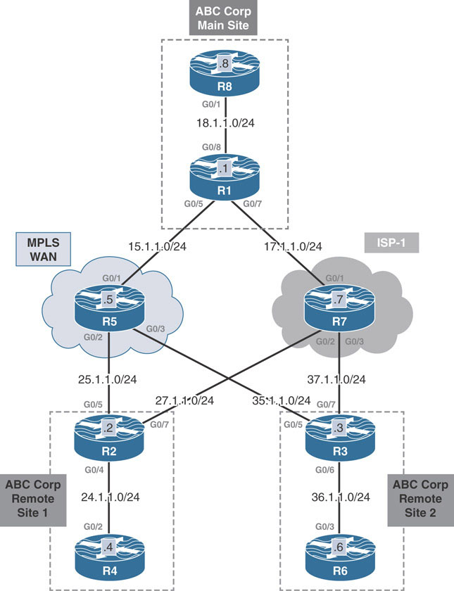
This lab should be conducted on the Enterprise Rack.
Lab Setup:
If you are using EVE-NG, and you have imported the EVE-NG topology from the EVE-NG-Topology folder, ignore the following and use Lab-2-Single Hub Single Cloud in the DMVPN folder in EVE-NG.
To copy and paste the initial configurations, go to the Initial-config folder → DMVPN folder → Lab-2.
Implement Phase 1
Design Goal
ABC Corp is expanding into two remote sites. The company has purchased MPLS WAN and Internet service from separate service providers. XYZ Company requires high availability between the remote sites and the main site. The network engineers have decided to use both connections to provide high availability for the remote sites. The primary path taken should be through the MPLS WAN, using the Internet connection through ISP-1 as backup.
DMVPN Tunnel Configuration
When implementing single-hub, dual-cloud redundancy, the goal is to provide transport redundancy across the solution. With only a single transport, DMVPN connectivity relies on that transport working properly. With two transports, a backup path can be designated by the routing protocol to provide redundancy for both spoke-to-spoke resolutions and the data plane. The type of redundancy will vary depending on the DMVPN phase implemented.
The common thread that connects the configuration across all DMVPN phases, regardless of routing protocol, is how the DMVPN network is set up across the various transports. To complete the design goal stated above, each transport should have its own tunnel interface dedicated to it. From the hub’s (R1’s) perspective, two tunnel interfaces are created: tunnel 100 and tunnel 200. Tunnel 100 uses R1’s IP address 15.1.1.1 as source. 15.1.1.1 on R1 is the IP address of its interface connected to MPLS WAN. Tunnel 200 uses the source IP address 17.1.1.1, which is the IP address of its interface connected to the ISP-1.
The same is true on the spokes R2 and R3. Tunnel 100 will use a source address of their interface towards the MPLS WAN (25.1.1.2 and 35.1.1.3, respectively). Tunnel 200 will use a source address of their interface towards ISP-1 (27.1.1.2 and 37.1.1.3, respectively).
Because the tunnel interfaces on all routers use different source addresses, the routers can distinguish between the two tunnels configured in the lab. Also, each tunnel on each router is configured with a separate NHRP network ID. This configuration allows the routers to keep track of which DMVPN cloud the tunnel interfaces belong. It is not necessary for the network IDs to match between the routers. The configuration is only locally significant. However, similar ID schemes are used for ease of troubleshooting and understanding. Tunnel 100 will be assigned network ID 100 and Tunnel 200 will be assigned network ID 200 on all routers.
The following configures the Tunnel 100 and Tunnel 200 interfaces on R1, R2, and R3:
On R1:
R1(config)#interface tunnel 100 R1(config-if)#ip address 100.1.1.1 255.255.255.0 R1(config-if)#tunnel source 15.1.1.1 R1(config-if)#tunnel mode gre multipoint R1(config-if)#ip nhrp network-id 100 R1(config-if)#ip nhrp map multicast dynamic R1(config)#interface tunnel 200 R1(config-if)#ip address 200.1.1.1 255.255.255.0 R1(config-if)#tunnel source 17.1.1.1 R1(config-if)#tunnel mode gre multipoint R1(config-if)#ip nhrp network-id 200 R1(config-if)#ip nhrp map multicast dynamic
On R2:
R2(config)#interface tunnel 100 R2(config-if)#ip address 100.1.1.2 255.255.255.0 R2(config-if)#tunnel source 25.1.1.2 R2(config-if)#tunnel destination 15.1.1.1 R2(config-if)#ip nhrp network-id 100 R2(config-if)#ip nhrp nhs 100.1.1.1 R2(config)#interface tunnel 200 R2(config-if)#ip address 200.1.1.2 255.255.255.0 R2(config-if)#tunnel source 27.1.1.2 R2(config-if)#tunnel destination 17.1.1.1 R2(config-if)#ip nhrp network-id 200 R2(config-if)#ip nhrp nhs 200.1.1.1
On R3:
R3(config)#interface tunnel 100 R3(config-if)#ip address 100.1.1.3 255.255.255.0 R3(config-if)#tunn source 35.1.1.3 R3(config-if)#tunnel destination 15.1.1.1 R3(config-if)#ip nhrp network-id 100 R3(config-if)#ip nhrp nhs 100.1.1.1 R3(config-if)#interface tunnel 200 R3(config-if)#ip address 200.1.1.3 255.255.255.0 R3(config-if)#tunnel source 37.1.1.3 R3(config-if)#tunnel destination 17.1.1.1 R3(config-if)#ip nhrp network-id 200 R3(config-if)#ip nhrp nhs 200.1.1.1
The show dmvpn command output is then used to verify the status of the tunnels. As seen below, the Tunnel 100 and Tunnel 200 interfaces are both up:
On R1:
R1#show dmvpn | begin Peer NBMA|Tunnel
UpDn Time --> Up or Down Time for a Tunnel
=====================================================================
===
Interface: Tunnel100, IPv4 NHRP Details
Type:Hub, NHRP Peers:2,
# Ent Peer NBMA Addr Peer Tunnel Add State UpDn Tm Attrb
----- --------------- --------------- ----- -------- -----
1 25.1.1.2 100.1.1.2 UP 00:38:42 D
1 35.1.1.3 100.1.1.3 UP 00:03:50 D
Interface: Tunnel200, IPv4 NHRP Details
Type:Hub, NHRP Peers:2,
# Ent Peer NBMA Addr Peer Tunnel Add State UpDn Tm Attrb
----- --------------- --------------- ----- -------- -----
1 27.1.1.2 200.1.1.2 UP 00:36:58 D
1 37.1.1.3 200.1.1.3 UP 00:01:45 D
Reachability to the Tunnel 100 interfaces is verified below by issuing traceroutes from R2 to R1 and R3’s tunnel 100 interface IP addresses:
On R2:
R2#traceroute 100.1.1.1 numeric Type escape sequence to abort. Tracing the route to 100.1.1.1 VRF info: (vrf in name/id, vrf out name/id) 1 100.1.1.1 5 msec * 4 msec R2#traceroute 100.1.1.3 numeric Type escape sequence to abort. Tracing the route to 100.1.1.3 VRF info: (vrf in name/id, vrf out name/id) 1 100.1.1.1 43 msec 8 msec 8 msec 2 100.1.1.3 52 msec * 10 msec
Reachability to the Tunnel 200 interfaces is verified below by issuing traceroutes from R2 to R1 and R3’s tunnel 200 interface IP addresses:
On R2:
R2#traceroute 200.1.1.1 numeric Type escape sequence to abort. Tracing the route to 200.1.1.1 VRF info: (vrf in name/id, vrf out name/id) 1 200.1.1.1 8 msec * 4 msec R2#traceroute 200.1.1.3 numeric Type escape sequence to abort. Tracing the route to 200.1.1.3 VRF info: (vrf in name/id, vrf out name/id) 1 200.1.1.1 4 msec 6 msec 6 msec 2 200.1.1.3 9 msec * 6 msec
Note
While implementing a single hub, dual cloud DMVPN is technically possible. it is not without some inherent limitations that limit its scalability and viability. Most of these issues stem from the fact that two tunnel interfaces are required to implement the DMVPN over two separate transports. In certain failure scenarios, routers may attempt to reach a neighboring DMVPN endpoint over a transport over which that specific neighbor has experienced a failure.
For example, in the Single Hub | Dual Cloud topology diagram, R1, R2, and R3 have two tunnel interfaces over two transports: the MPLS-WAN and the ISP-1. If R2 experiences a failure that disconnects it from the MPLS WAN, depending on the routing protocol and DMVPN phase, this failure may not affect R3’s decision when trying to route packets to R2. R3 may still try to reach R2 using the MPLS WAN instead of switching over to the ISP transport.
Solving these connectivity problems is outside of the scope of this lab guide, but some potential solutions will be briefly mentioned where applicable.
Implement OSPF
This section covers the implementation of DMVPN Phase 1 with OSPF to fulfill the task requirements. This solution is tailored to the specific task above and serves as a guide for solving similar tasks.
The primary difference between the single hub, single cloud and single-hub, dual-cloud designs is the second tunnel interface for the second DMVPN cloud. From OSPF’s perspective, adjacencies will form over both tunnel interfaces. Because there are no next hop considerations in DMVPN Phase 1, broadcast or point-to-point/point-to-multipoint network types can both be used.
OSPF interface costs can then be modified to provide preference to one tunnel interface over the other.
Broadcast Network Type
The primary concern for the broadcast network type is the placement of the DR for the broadcast segment. The hub should be chosen as the DR for both DMVPN tunnel interfaces, and the spokes should be ineligible to become the DR/BDR by having their OSPF priority set to 0 on both DMVPN tunnel interfaces.
Below is the initial OSPF configuration for both tunnel 100 and tunnel 200 on the hub R1 and spokes R2 and R3. OSPF process 100 for Area 0 is enabled on the tunnel interfaces. The host networks at each site are advertised into OSPF Area 0, and their network interfaces are declared passive to prevent any OSPF adjacencies over them. Notice the setting of the priority values on each interface on the spokes:
On R1:
R1(config)#interface tunnel 100 R1(config-if)#ip ospf network broadcast R1(config-if)#ip ospf 100 area 0 R1(config)#interface tunnel 200 R1(config-if)#ip ospf network broadcast R1(config-if)#ip ospf 100 area 0 R1(config-if)#interface g0/8 R1(config-if)#ip ospf 100 area 0 R1(config-if)#router ospf 100 R1(config-router)#passive-interface g0/8
On R2:
R2(config)#interface tunnel 100 R2(config-if)#ip ospf network broadcast R2(config-if)#ip ospf priority 0 R2(config-if)#ip ospf 100 area 0
You should see the following console message:
%OSPF-5-ADJCHG: Process 100, Nbr 200.1.1.1 on Tunnel100 from LOADING
to FULL, Loading Done
R2(config)#interface tunnel 200
R2(config-if)#ip ospf network broadcast
R2(config-if)#ip ospf priority 0
R2(config-if)#ip ospf 100 area 0
You should see the following console message:
%OSPF-5-ADJCHG: Process 100, Nbr 200.1.1.1 on Tunnel200 from LOADING
to FULL, Loading Done
R2(config)#interface g0/4
R2(config-if)#ip ospf 100 area 0
R2(config)#router ospf 100
R2(config-router)#passive-interface g0/4
On R3:
R3(config)#interface tunnel 100 R3(config-if)#ip ospf network broadcast R3(config-if)#ip ospf priority 0 R3(config-if)#ip ospf 100 area 0
You should see the following console message:
%OSPF-5-ADJCHG: Process 100, Nbr 200.1.1.1 on Tunnel100 from LOADING
to FULL, Loading Done
R3(config)#interface tunnel 200
R3(config-if)#ip ospf network broadcast
R3(config-if)#ip ospf priority 0
R3(config-if)#ip ospf 100 area 0
You should see the following console message:
%OSPF-5-ADJCHG: Process 100, Nbr 200.1.1.1 on Tunnel200 from LOADING
to FULL, Loading Done
R3(config)#interface g0/6
R3(config-if)#ip ospf 100 area 0
R3(config)#router ospf 100
R3(config-router)#passive-interface g0/6
The above configuration results in OSPF adjacencies over both tunnel interfaces between the spokes and the hub router. The show ip ospf neighbor command from the spokes below verifies this:
On R2:
R2#show ip ospf neighbor Neighbor ID Pri State Dead Time Address Interface 200.1.1.1 1 FULL/DR 00:00:39 200.1.1.1 Tunnel200 200.1.1.1 1 FULL/DR 00:00:31 100.1.1.1 Tunnel100
On R3:
R3#show ip ospf neighbor Neighbor ID Pri State Dead Time Address Interface 200.1.1.1 1 FULL/DR 00:00:33 200.1.1.1 Tunnel200 200.1.1.1 1 FULL/DR 00:00:35 100.1.1.1 Tunnel100
The show ip route ospf command is then issued on R1, R2, and R3. Notice in the output below, with the default OSPF settings, the routers are performing ECMP for each other’s LAN networks:
On R1:
R1#show ip route ospf | begin Gate
Gateway of last resort is not set
24.0.0.0/24 is subnetted, 1 subnets
O 24.1.1.0 [110/1001] via 200.1.1.2, 00:08:55, Tunnel200
[110/1001] via 100.1.1.2, 00:08:55, Tunnel100
36.0.0.0/24 is subnetted, 1 subnets
O 36.1.1.0 [110/1001] via 200.1.1.3, 00:02:46, Tunnel200
[110/1001] via 100.1.1.3, 00:02:46, Tunnel100
On R2:
R2#show ip route ospf | begin Gate
Gateway of last resort is not set
18.0.0.0/24 is subnetted, 1 subnets
O 18.1.1.0 [110/1001] via 200.1.1.1, 00:10:37, Tunnel200
[110/1001] via 100.1.1.1, 00:12:04, Tunnel100
36.0.0.0/24 is subnetted, 1 subnets
O 36.1.1.0 [110/1001] via 200.1.1.3, 00:03:34, Tunnel200
[110/1001] via 100.1.1.3, 00:03:34, Tunnel100
On R3:
R3#show ip route ospf | begin Gate
Gateway of last resort is not set
18.0.0.0/24 is subnetted, 1 subnets
O 18.1.1.0 [110/1001] via 200.1.1.1, 00:05:37, Tunnel200
[110/1001] via 100.1.1.1, 00:06:44, Tunnel100
24.0.0.0/24 is subnetted, 1 subnets
O 24.1.1.0 [110/1001] via 200.1.1.2, 00:05:37, Tunnel200
[110/1001] via 100.1.1.2, 00:06:44, Tunnel100
The routers load share between the two interfaces is because of the default OSPF costs on the tunnel interfaces. By default, GRE tunnels have an artificially high cost of 1000 as shown below. When added to the Gigabit Ethernet cost of 1, the resulting cost of prefixes learned through both tunnels is the 1001 shown in the routing table output above.
On R1:
R1#show ip ospf interface brief Interface PID Area IP Address/Mask Cost State Nbrs F/C Gi8 100 0 18.1.1.1/24 1 DR 0/0 Tu200 100 0 200.1.1.1/24 1000 DR 2/2 Tu100 100 0 100.1.1.1/24 1000 DR 2/2
On R2:
R2#show ip ospf interface brief Interface PID Area IP Address/Mask Cost State Nbrs F/C Gi4 100 0 24.1.1.2/24 1 DR 0/0 Tu200 100 0 200.1.1.2/24 1000 DROTH 1/1 Tu100 100 0 100.1.1.2/24 1000 DROTH 1/1
On R3:
R3#show ip ospf interface brief Interface PID Area IP Address/Mask Cost State Nbrs F/C Gi6 100 0 36.1.1.3/24 1 DR 0/0 Tu200 100 0 200.1.1.3/24 1000 DROTH 1/1 Tu100 100 0 100.1.1.3/24 1000 DROTH 1/1
The task requires the MPLS-WAN transport to be preferred over ISP-1. Therefore, the interface cost on all routers for tunnel 100 and tunnel 200 should be modified: Either set the cost lower on tunnel 100 or higher on tunnel 200. The solution here chooses to lower the cost on the tunnel 100 interface with the ip ospf cost 500 command. Remember that the default cost of a tunnel interface is 1000.
On R1, R2, and R3:
R1(config)#interface tunnel 100 R1(config-if)#ip ospf cost 500
With a lower OSPF cost over Tunnel 100, the routing table on R1, R2, and R3 now shows a single path to remote host networks that traverses MPLS-WAN transport. The next hop IP address for the 24.1.1.0/24 network on R3 and the 36.1.1.0/24 network on R2 is set to R2 and R3’s tunnel IP address, respectively. This is because the true next hop is retained when using OSPF’s broadcast network type. As already mentioned earlier, the preservation of the original next hop does not present any problem since in Phase 1 because the GRE tunnels on the spokes are point-to-point:
On R1:
R1#show ip route ospf | begin Gate
Gateway of last resort is not set
24.0.0.0/24 is subnetted, 1 subnets
O 24.1.1.0 [110/501] via 100.1.1.2, 00:02:01, Tunnel100
36.0.0.0/24 is subnetted, 1 subnets
O 36.1.1.0 [110/501] via 100.1.1.3, 00:02:01, Tunnel100
On R2:
R2#show ip route ospf | begin Gate
Gateway of last resort is not set
18.0.0.0/24 is subnetted, 1 subnets
O 18.1.1.0 [110/501] via 100.1.1.1, 00:02:45, Tunnel100
36.0.0.0/24 is subnetted, 1 subnets
O 36.1.1.0 [110/501] via 100.1.1.3, 00:02:45, Tunnel100
On R3:
R3#show ip route ospf | begin Gateway
Gateway of last resort is not set
18.0.0.0/24 is subnetted, 1 subnets
O 18.1.1.0 [110/501] via 100.1.1.1, 00:03:43, Tunnel100
24.0.0.0/24 is subnetted, 1 subnets
O 24.1.1.0 [110/501] via 100.1.1.2, 00:03:43, Tunnel100
After the configuration changes are made, a traceroute from R4 to R8, R6 to R8, and R4 to R6 takes the path through MPLS-WAN (tunnel 100) instead of ISP-1:
On R4:
R4#traceroute 18.1.1.8 probe 1 Type escape sequence to abort. Tracing the route to 18.1.1.8 VRF info: (vrf in name/id, vrf out name/id) 1 24.1.1.2 14 msec 2 100.1.1.1 10 msec 3 18.1.1.8 19 msec
On R6:
R6#traceroute 18.1.1.8 probe 1 Type escape sequence to abort. Tracing the route to 18.1.1.8 VRF info: (vrf in name/id, vrf out name/id) 1 36.1.1.3 80 msec 2 100.1.1.1 6 msec 3 18.1.1.8 12 msec
On R4:
R4#traceroute 36.1.1.6 probe 1 Type escape sequence to abort. Tracing the route to 36.1.1.6 VRF info: (vrf in name/id, vrf out name/id) 1 24.1.1.2 14 msec 2 100.1.1.1 8 msec 3 100.1.1.3 9 msec 4 36.1.1.6 12 msec
Next, to test redundancy, pings are repeated between R4 and R6. During the pings, the G0/5 interface is shut down on R1 to simulate the primary path via MPLS-WAN failure. The output below shows the results of the simulation:
On R4:
R4#ping 36.1.1.6 repeat 100000
Type escape sequence to abort.
Sending 100000, 100-byte ICMP Echos to 36.1.1.6, timeout is 2 seconds:
!!!!!!!!!!!!!!!!!!!!!!!!!!!!!!!!!!!!!!!!!!!!!!!!!!!!!!!!!!!!!!!!!!!!!!
!!!!!!!!!!!!!!!!!!!!!!!!!!!!!!!!!!!!!!!!!!!!!!!!!!!!!!!!!!!!!!!!!!!!!!
!!!!!!!!!!!!!!!!!!!!!!!!!!!!!!!!!!!!!!!!!!!!!!!!!!!!!!!!!!!!!!!!!!!!!!
!!!!!!!!!!!!!!!!!!!!!!!!!!!!!!!!!!!!!!!!!!!!!!!!!!!!!!!!!!!!!!!!!!!!!!
!!!!!!!!!!!!!!!!!!!!!!!!!!!!!!!!!!!!!!!!!!!!!!!!!!!!!!!!!!!!!!!!!!!!!!
!!!!!!!!!!!!!!!!!!!!!!!!!!!!!!!!!!!!!!!!!!!!!!!!!!!!!!!!!!!!!!!!!!!!!!
!!!!!!!!!!!!!!!!!!!!!!!!!!!!!!!!!!!!!!!!!!!!!!!!!!!!!!!!....!!!!!!!!!!
!!!!!!!!!!!!!!!!!!!!!!!!!!!!!!!!!!!!!!!!!!!!!!!!!!!!!!!!!!!!!!!!!!!!!!
!!!!!!!!!!!!!!!!!!!!!!!!!!!!!!!!!!!!!!!!!!!!!!!!!!!!!!!!!!!!!!!!!!!!!!
!!!!!!!!!!!!!!!!!!!!!!!!!!!!!!!!!!!!!!!!
Success rate is 99 percent (666/670), round-trip min/avg/max =
8/21/122 ms
The four yellow highlighted dots in between represent the roughly 8 seconds it took for the spoke routers R2 and R3 to switch to the secondary path through their tunnel 200 interface. The output below from R2 and R3 now shows the path to the remote host network on R2 and R3 via the backup tunnel 200:
On R2:
R2#show ip route ospf 123 | begin Gate
Gateway of last resort is not set
18.0.0.0/24 is subnetted, 1 subnets
O 18.1.1.0 [110/1001] via 200.1.1.1, 00:04:07, Tunnel200
36.0.0.0/24 is subnetted, 1 subnets
O 36.1.1.0 [110/1001] via 200.1.1.3, 00:04:07, Tunnel200
On R3:
R3#show ip route ospf 123 | begin Gate
Gateway of last resort is not set
18.0.0.0/24 is subnetted, 1 subnets
O 18.1.1.0 [110/1001] via 200.1.1.1, 00:04:42, Tunnel200
24.0.0.0/24 is subnetted, 1 subnets
O 24.1.1.0 [110/1001] via 200.1.1.2, 00:04:42, Tunnel200
Point-to-Point and Point-to-Multipoint Network Types
To implement this design, the hub R1’s tunnel interfaces 100 and 200 are configured to use OSPF’s point-to-multipoint network type. Tunnel interfaces 100 and 200 on spokes R2 and R3 run OSPF’s point-to-point network type. The OSPF hello interval timer on R1’s point-to-multipoint tunnel interfaces is modified to match the hello interval timer of the spokes’ point-to-point tunnel interfaces with the ip ospf hello-interval 10 command:
On R1:
R1(config)#interface g0/5
R1(config-if)#no shut
On R1, R2, and R3:
Rx(config)#interface tunnel 100
Rx(config-if)#no ip ospf cost 500
On R1:
R1(config)#interface tunnel 100 R1(config-if)#ip ospf network point-to-multipoint R1(config-if)#ip ospf hello-interval 10 R1(config)#interface tunnel 200 R1(config-if)#ip ospf network point-to-multipoint R1(config-if)#ip ospf hello-interval 10
The OSPF configuration for the host facing interfaces has been retained from the earlier task. As such, this configuration is not required here.
On R2:
R2(config)#interface tunnel 100 R2(config-if)#ip ospf network point-to-point
You should see the following console message:
%OSPF-5-ADJCHG: Process 100, Nbr 200.1.1.1 on Tunnel100 from LOADING
to FULL, Loading Done
R2(config)#interface tunnel 200
R2(config-if)#ip ospf network point-to-point
You should see the following console message:
%OSPF-5-ADJCHG: Process 100, Nbr 200.1.1.1 on Tunnel200 from LOADING
to FULL, Loading DoneOn R3:
R3(config)#interface tunnel 100 R3(config-if)#ip ospf network point-to-point
You should see the following console message:
%OSPF-5-ADJCHG: Process 100, Nbr 200.1.1.1 on Tunnel100 from LOADING
to FULL, Loading Done
R3(config)#interface tunnel 200
R3(config-if)#ip ospf network point-to-point
You should see the following console message:
%OSPF-5-ADJCHG: Process 100, Nbr 200.1.1.1 on Tunnel200 from LOADING
to FULL, Loading DoneAfter completing the above, OSPF adjacencies are formed between the spokes and the hub router over both tunnel interfaces. The show ip route ospf command output below shows the host networks from each site learned via OSPF. The routing table on all routers reveals equal cost load sharing between the two tunnel interfaces for the host networks. Similar to the broadcast network type implementation, the load sharing is a result of the equal default cost on the tunnel interfaces.
Also notice the next hop addresses for the 36.1.1.0/24 network on R2 and the 24.1.1.0/24 network on R3 is set to the hub’s tunnel IP address. This is the expected behavior when implementing the P2P/P2MP network in the DMVPN where the original next hop addresses are not retained.
On R1:
R1#show ip route ospf | begin Gate
Gateway of last resort is not set
24.0.0.0/24 is subnetted, 1 subnets
O 24.1.1.0 [110/1001] via 200.1.1.2, 00:00:34, Tunnel200
[110/1001] via 100.1.1.2, 00:00:34, Tunnel100
36.0.0.0/24 is subnetted, 1 subnets
O 36.1.1.0 [110/1001] via 200.1.1.3, 00:00:34, Tunnel200
[110/1001] via 100.1.1.3, 00:00:34, Tunnel100
On R2:
R2#show ip route ospf | begin Gate
Gateway of last resort is not set
18.0.0.0/24 is subnetted, 1 subnets
O 18.1.1.0 [110/1001] via 200.1.1.1, 00:01:21, Tunnel200
[110/1001] via 100.1.1.1, 00:01:21, Tunnel100
36.0.0.0/24 is subnetted, 1 subnets
O 36.1.1.0 [110/2001] via 200.1.1.1, 00:00:59, Tunnel200
[110/2001] via 100.1.1.1, 00:00:59, Tunnel100
100.0.0.0/8 is variably subnetted, 3 subnets, 2 masks
O 100.1.1.1/32 [110/1000] via 200.1.1.1, 00:01:21, Tunnel200
[110/1000] via 100.1.1.1, 00:01:21, Tunnel100
200.1.1.0/24 is variably subnetted, 3 subnets, 2 masks
O 200.1.1.1/32 [110/1000] via 200.1.1.1, 00:01:21, Tunnel200
[110/1000] via 100.1.1.1, 00:01:21, Tunnel100
On R3:
R3#show ip route ospf | begin Gate
Gateway of last resort is not set
18.0.0.0/24 is subnetted, 1 subnets
O 18.1.1.0 [110/1001] via 200.1.1.1, 00:02:38, Tunnel200
[110/1001] via 100.1.1.1, 00:02:38, Tunnel100
24.0.0.0/24 is subnetted, 1 subnets
O 24.1.1.0 [110/2001] via 200.1.1.1, 00:01:26, Tunnel200
[110/2001] via 100.1.1.1, 00:01:26, Tunnel100
100.0.0.0/8 is variably subnetted, 3 subnets, 2 masks
O 100.1.1.1/32 [110/1000] via 200.1.1.1, 00:02:38, Tunnel200
[110/1000] via 100.1.1.1, 00:02:38, Tunnel100
200.1.1.0/24 is variably subnetted, 3 subnets, 2 masks
O 200.1.1.1/32 [110/1000] via 200.1.1.1, 00:02:38, Tunnel200
[110/1000] via 100.1.1.1, 00:02:38, Tunnel100
To complete the task, OSPF cost on the Tunnel 100 interface on R1, R2, and R3 is modified to 500 with the ip ospf cost 500 command. This makes the MPLS-WAN the primary path and the internet service from ISP-1 as the backup. The OSPF process ID can also be manipulated. In OSPF, the lower process id is a better path for the same type of routes. Another method is to use NHS Cluster; this will be tested in later labs.
On R1, R2, and R3:
Rx(config)#interface tunnel 100 Rx(config-if)#ip ospf cost 500
On R1:
R1#show ip route ospf | begin Gate
Gateway of last resort is not set
24.0.0.0/24 is subnetted, 1 subnets
O 24.1.1.0 [110/501] via 100.1.1.2, 00:01:05, Tunnel100
36.0.0.0/24 is subnetted, 1 subnets
O 36.1.1.0 [110/501] via 100.1.1.3, 00:01:05, Tunnel100
On R2:
R2#show ip route ospf | begin Gate
Gateway of last resort is not set
18.0.0.0/24 is subnetted, 1 subnets
O 18.1.1.0 [110/501] via 100.1.1.1, 00:01:26, Tunnel100
36.0.0.0/24 is subnetted, 1 subnets
O 36.1.1.0 [110/1001] via 100.1.1.1, 00:01:26, Tunnel100
100.0.0.0/8 is variably subnetted, 3 subnets, 2 masks
O 100.1.1.1/32 [110/500] via 100.1.1.1, 00:01:26, Tunnel100
200.1.1.0/24 is variably subnetted, 3 subnets, 2 masks
O 200.1.1.1/32 [110/500] via 100.1.1.1, 00:01:26, Tunnel100
On R3:
R3#show ip route ospf | begin Gate
Gateway of last resort is not set
18.0.0.0/24 is subnetted, 1 subnets
O 18.1.1.0 [110/501] via 100.1.1.1, 00:01:56, Tunnel100
24.0.0.0/24 is subnetted, 1 subnets
O 24.1.1.0 [110/1001] via 100.1.1.1, 00:01:56, Tunnel100
100.0.0.0/8 is variably subnetted, 3 subnets, 2 masks
O 100.1.1.1/32 [110/500] via 100.1.1.1, 00:01:56, Tunnel100
200.1.1.0/24 is variably subnetted, 3 subnets, 2 masks
O 200.1.1.1/32 [110/500] via 100.1.1.1, 00:01:56, Tunnel100
To test redundancy, pings are repeated from R4 to R6. During the pings, the G0/5 interface is shut down on R1 to simulate a failure. The output below shows the results of the simulation:
On R4:
R4#ping 36.1.1.6 repeat 100000
Type escape sequence to abort.
Sending 100000, 100-byte ICMP Echos to 36.1.1.6, timeout is 2 seconds:
!!!!!!!!!!!!!!!!!!!!!!!!!!!!!!!!!!!!!!!!!!!!!!!!!!!!!!!!!!!!!!!!!!!!!!
!!!!!!!!!!!!!!!!!!!!!!!!!!!!!!!!!!!!!!!!!!!!!!!!!!!!!!!!!!!!!!!!!!!!!!
!!!!!!!!!!!!!!!!!!!!!!!!!!!!!!!!!!!!!!!!!!!!!!!!!!!!!!!!!!!!!!!!!!!!!!
!!!!!!!!!!!!!!!!!!!!!!!!!!!!!!!!!!!!!!!!!!!!!!!!!!!!!!!!!!!!!!!!!!!!!!
!!!!!!!!!!!....!!!!!!!!!!!!!!!!!!!!!!!!!!!!!!!!!!!!!!!!!!!!!!!!!!!!!!!
!!!!!!!!!!!!!!!!!!!!!!!!!!!!!!!!!!!!!!!!!!!!!!!!!!!!!!!!!!!!!!!!!!!!!!
!!!!!!!!!!!!!!!!!!!!!!!!!!!!!!!!!!!!!!!!!!!!!!!!!!!!!!!!!!!!!!!!!!!!!!
!!!!!!!!!!!!!!!!!!!!!!!!!!!!
Success rate is 98 percent (511/519), round-trip min/avg/max = 9/21/40
ms
Much as in the case of the broadcast network type, the yellow highlighted dots above represent roughly the time it took for the spoke routers to switch to the secondary path via ISP-1 through their tunnel 200 interface. The routing tables on R2 and R3 now use the backup path via tunnel 200 over the ISP-1 transport:
On R2:
R2#show ip route ospf | begin Gate
Gateway of last resort is not set
18.0.0.0/24 is subnetted, 1 subnets
O 18.1.1.0 [110/1001] via 200.1.1.1, 00:02:42, Tunnel200
36.0.0.0/24 is subnetted, 1 subnets
O 36.1.1.0 [110/2001] via 200.1.1.1, 00:02:42, Tunnel200
200.1.1.0/24 is variably subnetted, 3 subnets, 2 masks
O 200.1.1.1/32 [110/1000] via 200.1.1.1, 00:02:42, Tunnel200
On R3:
R3#show ip route ospf | begin Gate
Gateway of last resort is not set
18.0.0.0/24 is subnetted, 1 subnets
O 18.1.1.0 [110/1001] via 200.1.1.1, 00:03:12, Tunnel200
24.0.0.0/24 is subnetted, 1 subnets
O 24.1.1.0 [110/2001] via 200.1.1.1, 00:03:12, Tunnel200
200.1.1.0/24 is variably subnetted, 3 subnets, 2 masks
O 200.1.1.1/32 [110/1000] via 200.1.1.1, 00:03:12, Tunnel200
Implement EIGRP
EIGRP for Single Hub | Dual Cloud is implemented by enabling the same EIGRP process on both the tunnel interfaces with the network command under the EIGRP router configuration mode. The network command is also used to advertise the host networks at each site into the same EIGRP process. These interfaces are declared as passive interfaces with the passive-interface command under the EIGRP router configuration mode as shown below. However, before this solution is implemented, the OSPF 100 configuration from the earlier task is removed and the G0/5 interface on R1 is brought back up:
On R1, R2, and R3:
Rx(config)#no router ospf 100
On R1:
R1(config)#interface g0/5
R1(config-if)#no shut
R1(config)#router eigrp 100
R1(config-router)#network 18.1.1.1 0.0.0.0
R1(config-router)#network 100.1.1.1 0.0.0.0
R1(config-router)#network 200.1.1.1 0.0.0.0
R1(config-router)#passive-interface g0/8
On R2:
R2(config)#router eigrp 100 R2(config-router)#network 24.1.1.2 0.0.0.0 R2(config-router)#network 100.1.1.2 0.0.0.0 R2(config-router)#network 200.1.1.2 0.0.0.0 R2(config-router)#passive-interface g0/4
You should see the following console messages:
%DUAL-5-NBRCHANGE: EIGRP-IPv4 100: Neighbor 100.1.1.1 (Tunnel100) is up: new adjacency %DUAL-5-NBRCHANGE: EIGRP-IPv4 100: Neighbor 200.1.1.1 (Tunnel200) is up: new adjacency
On R3:
R3(config)#router eigrp 100 R3(config-router)#network 36.1.1.3 0.0.0.0 R3(config-router)#network 100.1.1.3 0.0.0.0 R3(config-router)#network 200.1.1.3 0.0.0.0 R3(config-router)#passive-interface g0/6
You should see the following console messages:
%DUAL-5-NBRCHANGE: EIGRP-IPv4 100: Neighbor 100.1.1.1 (Tunnel100) is up: new adjacency %DUAL-5-NBRCHANGE: EIGRP-IPv4 100: Neighbor 200.1.1.1 (Tunnel200) is up: new adjacency
The above results in EIGRP neighborships between R2 and R1 and between R3 and R1 over their tunnel 100 and tunnel 200 interfaces:
On R2:
R2#show ip eigrp 100 neighbors
EIGRP-IPv4 Neighbors for AS(100)
H Address Interface Hold Uptime SRTT RTO Q
Seq
(sec) (ms) Cnt
Num
1 100.1.1.1 Tu100 11 00:03:24 3 1470 0 16
0 200.1.1.1 Tu200 13 00:07:29 9 1470 0 15
On R3:
R3#show ip eigrp 100 neighbors
EIGRP-IPv4 Neighbors for AS(100)
H Address Interface Hold Uptime SRTT RTO Q Seq
(sec) (ms) Cnt
Num
1 100.1.1.1 Tu100 10 00:05:21 5 1470 0 16
0 200.1.1.1 Tu200 13 00:06:23 4 1470 0 17
Hub R1 is configured to send EIGRP summary default routes to the spokes over its tunnel interfaces with the ip summary-address command:
On R1:
R1(config)#interface tunnel 100 R1(config-if)#ip summary-address eigrp 100 0.0.0.0 0.0.0.0 R1(config)#interface tunnel 200 R1(config-if)#ip summary-address eigrp 100 0.0.0.0 0.0.0.0
The routing tables on spokes R2 and R3 show that they receive two default routes from the hub R1 over their tunnel 100 and 200 interfaces:
On R2:
R2#show ip route eigrp 100 | begin Gate
Gateway of last resort is 200.1.1.1 to network 0.0.0.0
D* 0.0.0.0/0 [90/26880256] via 200.1.1.1, 00:01:39, Tunnel200
[90/26880256] via 100.1.1.1, 00:01:39, Tunnel100
On R3:
R3#show ip route eigrp 100 | begin Gate
Gateway of last resort is 200.1.1.1 to network 0.0.0.0
D* 0.0.0.0/0 [90/26880256] via 200.1.1.1, 00:02:05, Tunnel200
[90/26880256] via 100.1.1.1, 00:02:05, Tunnel100
By default, R2 and R3 perform ECMP for the default routes. The reason for this is that the EIGRP metrics associated with the tunnel 100 and tunnel 200 interfaces are the same as shown below:
On R2:
R2#show interface tunnel 100 | include DLY MTU 9976 bytes, BW 100 Kbit/sec, DLY 50000 usec, R2#show interface tunnel 200 | include DLY MTU 9976 bytes, BW 100 Kbit/sec, DLY 50000 usec,
EIGRP uses the above bandwidth and delay metrics as part of its metric calculation algorithm. Because the metrics above have the same values, EIGRP computes equal costs for routes received from both interfaces.
To allow the spokes to use MPLS-WAN as the primary path, the delay on the tunnel 100 interface is lowered. This forces EIGRP to calculate a better metric through the tunnel 100 interface over the tunnel 200 interface, as shown below:
On R1, R2, and R3:
Rx(config)#interface tunnel 100 Rx(config-if)#delay 500
To verify the configuration:
Rx#show interface tunnel 100 | include DLY MTU 9976 bytes, BW 100 Kbit/sec, DLY 5000 usec,
On R1:
R1#show ip route eigrp 100 | begin Gate
Gateway of last resort is 0.0.0.0 to network 0.0.0.0
D* 0.0.0.0/0 is a summary, 00:09:12, Null0
24.0.0.0/24 is subnetted, 1 subnets
D 24.1.1.0 [90/25728256] via 100.1.1.2, 00:03:01, Tunnel100
36.0.0.0/24 is subnetted, 1 subnets
D 36.1.1.0 [90/25728256] via 100.1.1.3, 00:03:01, Tunnel100
On R2:
R2#show ip route eigrp 100 | begin Gate Gateway of last resort is 100.1.1.1 to network 0.0.0.0 D* 0.0.0.0/0 [90/25728256] via 100.1.1.1, 00:03:21, Tunnel100
On R3:
R3#show ip route eigrp 100 | begin Gate Gateway of last resort is 100.1.1.1 to network 0.0.0.0 D* 0.0.0.0/0 [90/25728256] via 100.1.1.1, 00:03:38, Tunnel100
With MPLS WAN as the primary path, redundancy is verified by performing a repeated ping from R4 to R6. During the ping, G0/5 interface on R1 is shut down. This results in loss of connectivity between R4 – R6 (evidenced by the yellow highlighted dots below). After a few seconds EIGRP installs the backup route through the Tunnel 200 interface, restoring communication.
On R4:
R4#ping 36.1.1.6 repeat 100000
Type escape sequence to abort.
Sending 100000, 100-byte ICMP Echos to 36.1.1.6, timeout is 2 seconds:
!!!!!!!!!!!!!!!!!!!!!!!!!!!!!!!!!!!!!!!!!!!!!!!!!!!!!!!!!!!!!!!!!!!!!!
!!!!!!!!!!!!!!!!!!!!!!!!!!!!!!!!!!!!!!!!!!!!!!!!!!!!!!!!!!!!!!!!!!!!!!
!!!!!!!!!!!!!!!!!!!!!!!!!!!!!!!!!!!!!!!!!!!!!!!!!!!!!!!!!!!!!!!!!!!!!!
!!!!!!!!!!!!!!!!!!!!!!!!!!!!!!!!!!!!!!!!!!!!!!!!!!!!!!!.......!!!!!!!!
!!!!!!!!!!!!!!!!!!!!!!!!!!!!!!!!!!!!!!!!!!!!!!!!!!!!!!!!!!!!!!!!!!!!!!
!!!!!!!!!!!!!!!!!!!!!!!!!!!!!!!!!!!!!!!!!!!!!!!!!!!!!!!
Success rate is 98 percent (398/405), round-trip min/avg/max = 8/21/67
ms
Implement iBGP
A major difference in the iBGP configuration for a single hub, dual cloud design lies in the peer group configuration. With such a design, it is desirable to configure different routing policies for each DMVPN cloud to prefer one transport over the other. Peer groups carry the restriction that all members of a peer group must have the same routing policies. As such, it is not possible to utilize a single peer group for the dynamic peering for both tunnel interfaces on the route reflector R1.
Instead, the tunnel 100 peer group is used for iBGP neighbors over tunnel 100 and the tunnel 200 peer group is used for iBGP neighbors over tunnel 200. The tunnel 100 peer group is associated with the dynamic listen range 100.1.1.0/24, the Tunnel 100 DMVPN overlay address. Likewise, the tunnel 200 peer group is associated with the 200.1.1.0/24 dynamic listen range corresponding to the Tunnel 200 DMVPN overlay addresses.
The result is two independent peer groups over which policies can be configured to affect the routing in the DMVPN overlay. The respective host networks at each site are advertised into BGP with the network statement. Before iBGP is configured, the EIGRP 100 configuration and any other leftover OSPF configuration commands from the earlier tasks should be removed on R1, R2, and R3.
On R1:
R1(config)#no router eigrp 100 R1(config)#interface g0/5 R1(config-if)#no shut R1(config)#interface tunnel 100 R1(config-if)#no delay 500 R1(config-if)#no ip ospf network point-to-multipoint R1(config-if)#no ip ospf hello-interval 10 R1(config)#interface tunnel 200 R1(config-if)#no ip ospf network point-to-multipoint R1(config-if)#no ip ospf hello-interval 10 R1(config)#router bgp 100 R1(config-router)#neighbor tunnel100 peer-group R1(config-router)#neighbor tunnel100 remote-as 100 R1(config-router)#neighbor tunnel200 peer-group R1(config-router)#neighbor tunnel200 remote-as 100 R1(config-router)#bgp listen range 100.1.1.0/24 peer-group tunnel100 R1(config-router)#bgp listen range 200.1.1.0/24 peer-group tunnel200 R1(config-router)#address-family ipv4 R1(config-router-af)#neighbor tunnel100 activate R1(config-router-af)#neighbor tunnel200 activate R1(config-router-af)#network 18.1.1.0 mask 255.255.255.0 R1(config-router-af)#neighbor tunnel100 route-reflector-client R1(config-router-af)#neighbor tunnel200 route-reflector-client
On R2:
R2(config)#no router eigrp 100 R2(config)#interface tunnel 100 R2(config-if)#no ip ospf network point-to-point R2(config-if)#no ip ospf cost 500 R2(config-if)#no delay 500 R2(config)#interface tunnel 200 R2(config-if)#no ip ospf network point-to-point R2(config)#router bgp 100 R2(config-router)#neighbor 100.1.1.1 remote-as 100 R2(config-router)#neighbor 200.1.1.1 remote-as 100 R2(config-router)#address-family ipv4 R2(config-router-af)#network 24.1.1.0 mask 255.255.255.0
You should see the following console messages:
%BGP-5-ADJCHANGE: neighbor 100.1.1.1 Up %BGP-5-ADJCHANGE: neighbor 200.1.1.1 Up
On R3:
R3(config)#no router eigrp 100 R3(config)#interface tunnel 100 R3(config-if)#no ip ospf network point-to-point R3(config-if)#no ip ospf cost 500 R3(config-if)#no delay 500 R3(config)#interface tunnel 200 R3(config-if)#no ip ospf network point-to-point R3(config)#router bgp 100 R3(config-router)#neighbor 100.1.1.1 remote 100 R3(config-router)#neighbor 200.1.1.1 remote 100 R3(config-router)#address-family ipv4 R3(config-router-af)#network 36.1.1.0 mask 255.255.255.0
You should see the following console messages:
%BGP-5-ADJCHANGE: neighbor 100.1.1.1 Up %BGP-5-ADJCHANGE: neighbor 200.1.1.1 Up
The above configuration results in two R1/R2 iBGP peerings and two R1/R3 iBGP peerings, one for each transport:
On R1:
R1#show ip bgp summary | begin Nei Neighbor V AS MsgRcvd MsgSent TblVer InQ OutQ Up/Down State/PfxRcd *100.1.1.2 4 100 16 19 6 0 0 00:08:12 1 *100.1.1.3 4 100 16 19 6 0 0 00:08:14 1 *200.1.1.2 4 100 242 245 6 0 0 03:35:21 1 *200.1.1.3 4 100 237 243 6 0 0 03:32:29 1 * Dynamically created based on a listen range command Dynamically created neighbors: 4, Subnet ranges: 2 BGP peergroup tunnel100 listen range group members: 100.1.1.0/24 BGP peergroup tunnel200 listen range group members: 200.1.1.0/24 Total dynamically created neighbors: 4/(100 max), Subnet ranges: 2
Next, the hub R1 is then configured to send a BGP default route to the spokes R2 and R3 via the iBGP peering over its tunnel 100 and 200 interfaces. The method used to propagate the default route is similar to what was configured in the earlier BGP designs:
On R1:
R1(config)#ip prefix-list NET permit 0.0.0.0/0 R1(config)#route-map TST permit 10 R1(config-route-map)#match ip address prefix NET R1(config)#router bgp 100 R1(config-router)#address-family ipv4 R1(config-router-af)#neighbor tunnel100 default-originate R1(config-router-af)#neighbor tunnel200 default-originate R1(config-router-af)#neighbor tunnel100 route-map TST out R1(config-router-af)#neighbor tunnel200 route-map TST out R1#clear ip bgp * out
The show ip bgp command is then issued on R1, R2, and R3. R1 has chosen the path via tunnel 100 as best for the host networks at the remote sites. R2 and R3 choose the path via tunnel 100 as best for the default route:
On R1:
R1#show ip bgp | begin Net
Network Next Hop Metric LocPrf Weight Path
0.0.0.0 0.0.0.0 0 i
*> 18.1.1.0/24 0.0.0.0 0 32768 i
*>i 24.1.1.0/24 100.1.1.2 0 100 0 i
* i 200.1.1.2 0 100 0 i
*>i 36.1.1.0/24 100.1.1.3 0 100 0 i
* i 200.1.1.3 0 100 0 i
On R2:
R2#show ip bgp | begin Net
Network Next Hop Metric LocPrf Weight Path
* i 0.0.0.0 200.1.1.1 0 100 0 i
*>i 100.1.1.1 0 100 0 i
*> 24.1.1.0/24 0.0.0.0 0 32768 i
On R3:
R3#show ip bgp | begin Net
Network Next Hop Metric LocPrf Weight Path
*>i 0.0.0.0 100.1.1.1 0 100 0 i
* i 200.1.1.1 0 100 0 i
*> 36.1.1.0/24 0.0.0.0 0 32768 i
To understand why R2 and R3 choose the path via tunnel 100 as best, the show ip bgp 0.0.0.0 command is issued on them:
On R2:
R2#show ip bgp 0.0.0.0
BGP routing table entry for 0.0.0.0/0, version 10
Paths: (2 available, best #2, table default)
Not advertised to any peer
Refresh Epoch 2
Local
200.1.1.1 from 200.1.1.1 (200.1.1.1)
Origin IGP, metric 0, localpref 100, valid, internal
rx pathid: 0, tx pathid: 0
Refresh Epoch 3
Local
100.1.1.1 from 100.1.1.1 (200.1.1.1)
Origin IGP, metric 0, localpref 100, valid, internal, best
rx pathid: 0, tx pathid: 0x0
On R3:
R3#show ip bgp 0.0.0.0
BGP routing table entry for 0.0.0.0/0, version 11
Paths: (2 available, best #1, table default)
Not advertised to any peer
Refresh Epoch 3
Local
100.1.1.1 from 100.1.1.1 (200.1.1.1)
Origin IGP, metric 0, localpref 100, valid, internal, best
rx pathid: 0, tx pathid: 0x0
Refresh Epoch 4
Local
200.1.1.1 from 200.1.1.1 (200.1.1.1)
Origin IGP, metric 0, localpref 100, valid, internal
rx pathid: 0, tx pathid: 0
As shown above, R2 and R3 choose the MPLS WAN path as their best path; this is the correct pathing choice, according to the design goals. The only issue is the reason behind the pathing decision. With all other BGP attributes tied, the BGP best-path algorithm reverts to step 13, choosing the lowest neighbor peering address as the deciding factor. R2 and R3 choose the path over tunnel 100 because the peering address is 100.1.1.1, as opposed to the higher address of 200.1.1.1 over tunnel 200.
While this is a deterministic decision, it does not provide stability. If for some reason the DMVPN overlay addresses were changed, the results of the BGP best-path algorithm could change as well. For this reason, it is best to influence a BGP attribute that is considered before the neighbor peering address at step 13. Local preference is a good choice for modification as it is one of the first attributes considered in the best-path algorithm.
To implement this consistent path choice, R1 assigns a local preference of 200 to all paths received from a member of the tunnel 100 peer group, as shown below. Likewise, R2 and R3 apply a local preference of 200 for all prefixes received from R1’s tunnel 100 peering address 100.1.1.1:
On R1:
R1(config)#route-map local-pref permit 10 R1(config-route-map)#set local-preference 200 R1(config)#router bgp 100 R1(config-router)#address-family ipv4 R1(config-router-af)#neighbor tunnel100 route-map local-pref in R1#clear ip bgp * in
On R2 and R3:
Rx(config)#route-map local-pref permit 10 Rx(config-route-map)#set local-pref 200 Rx(config)#router bgp 100 Rx(config-router)#address-family ipv4 Rx(config-router-af)#neighbor 100.1.1.1 route-map local-pref in Rx#clear ip bgp * in
On R1:
R1#show ip bgp | begin Net
Network Next Hop Metric LocPrf Weight Path
0.0.0.0 0.0.0.0 0 i
*> 18.1.1.0/24 0.0.0.0 0 32768 i
*>i 24.1.1.0/24 100.1.1.2 0 200 0 i
* i 200.1.1.2 0 100 0 i
*>i 36.1.1.0/24 100.1.1.3 0 200 0 i
* i 200.1.1.3 0 100 0 i
On R2:
R2#show ip bgp | begin Net
Network Next Hop Metric LocPrf Weight Path
* i 0.0.0.0 200.1.1.1 0 100 0 i
*>i 100.1.1.1 0 200 0 i
*> 24.1.1.0/24 0.0.0.0 0 32768 i
On R3:
R3#show ip bgp | begin Net
Network Next Hop Metric LocPrf Weight Path
*>i 0.0.0.0 100.1.1.1 0 200 0 i
* i 200.1.1.1 0 100 0 i
*> 36.1.1.0/24 0.0.0.0 0 32768 i
Redundancy can once again be checked by performing a repeated ping from R4 to R6. During the pings, the G0/5 interface on R1 is shut down. The yellow highlighted dots once again represent the time taken for R2 to start using the default route via the secondary path over the MPLS WAN transport through tunnel 200:
On R4:
R4#ping 36.1.1.6 repeat 100000 Type escape sequence to abort. Sending 100000, 100-byte ICMP Echos to 36.1.1.6, timeout is 2 seconds: !!!!!!!!!!!!!!!!!!!!!!!!!!!!!!!!!!!!!!!!!!!!!!!!!!!!!!!!!!!!!!!!!!!!!! !!!!!!!!!!!!!!!!!!!!!!!!!!!!!!!!!!!!!!!!!!!!!!!!!!!!!!!!!!!!!!!!!!!!!! !!!!!!!!!!!!!!!!!!!!!!!!!!!!!!!!!!!!!!!!!!!!!!!!!!!!!!!!!!!!!!!!!!!!!! !!!!!!!!!!!!!!!!!!!!!!!!!!!!!!!!!!!!!!!!!!!!!!!!!!!!!!!!!!!!!!!!!!.... ...................................................................... ...............!!!!!!!!!!!!!!!!!!!!!!!!!!!!!!!!!!!!!!!!!!!!!!!!!!!!!!! !!!!!!!!!!!!!!!!!!!!!!!!!!!!!!!!!!!!!!!!!!!!!!!!!!!!!!!!!!!!!!!!!!!!!! !!!!!!!!!!!!!!!!!!!!!!!!!!!!!!!!!!!!!!!!!!!!!!!!!!!!!!!!!!!!!!!!!!!!!! !!!!!!!!!!!!!!!!!!!!!!!!!!!!!!!!!!!!!!!!!!!!!!!!!!!!!!!!!!!!!!!!!!!!!! !!!!!!!!!!!!!!!!!!!!!!!!!!!!!!!!!!!!!!!!!!!!!!!!!!!!!!!!!!!!!!!!!!!!!! !!!!!!!!!!!!!!!!!!!!!!!!!!!!!!!!!! Success rate is 87 percent (645/734), round-trip min/avg/max = 9/21/102 ms
Note
The convergence time in this case is limited by the BGP keepalive and hold-down timers. The default keepalive timer for BGP is 60 seconds, and the default hold-down timer is 3 times the keepalive, or 180 seconds. With these defaults, it can take up to 3 minutes before BGP declares the neighbor down and begins the reconvergence process. If speedier convergence is the goal, before checking for redundancy, the keepalive timer and the hold-down timer for BGP can be lowered. This configuration would only have to be done on one router since BGP accepts the lower keepalive time between peers when the neighbors establish peering.
With this in mind, the hub is the logical choice for making this change since all other routers peer directly with it. The following configuration on the DMVPN hub router lowers the keepalive timer to 6 seconds and the hold-down timer to 20 seconds. It is applied to the peer group configuration for the spokes connected to a specific transport:
R1(config)#router bgp 100 R1(config-router)#neighbor SPOKES timers 6 20
The routing tables on R2 and R3 confirm that the secondary path via tunnel 200 over ISP-1 is in use:
On R2:
R2#show ip route bgp | begin Gate Gateway of last resort is 200.1.1.1 to network 0.0.0.0 B* 0.0.0.0/0 [200/0] via 200.1.1.1, 00:03:33
On R3:
R3#show ip route bgp | begin Gate Gateway of last resort is 200.1.1.1 to network 0.0.0.0 B* 0.0.0.0/0 [200/0] via 200.1.1.1, 00:04:24
Implement eBGP
Much as in the previous BGP sections, two design choices can be used for eBGP peerings between the hub and spokes. Spokes can either be configured to belong to different autonomous systems or to the same autonomous systems.
Spokes in Different Autonomous Systems
The following configurations implement the first design where the spokes R2 and R3 are placed in different autonomous systems—ASN 200 and ASN 300, respectively. They are configured to peer with the hub R1 (ASN 100) over their tunnel 100 and tunnel 200 interfaces. Respective host networks at each site are advertised into BGP with the network statement. In addition, because this is Phase 1, the hub R1 can be configured to propagate a default route to the spokes while suppressing the more specific networks.
On R1:
Before configuring this task, you need to remove BGP AS 100 with the no router bgp 100 command and issue a no shut on the G0/5 interface. The prefix list and the route map should already be part of the running configuration because they were configured previously.
R1(config)#no router bgp 100 R1(config)#interface g0/5 R1(config-if)#no shut R1#show run | include ip prefix ip prefix-list NET seq 5 permit 0.0.0.0/0 R1#show run | section route-map TST route-map TST permit 10 match ip address prefix-list NET R1(config)#router bgp 100 R1(config-router)#neighbor tunnel100 peer-group R1(config-router)#neighbor tunnel200 peer-group R1(config-router)#neighbor tunnel100 remote-as 200 alternate-as 300 R1(config-router)#neighbor tunnel200 remote-as 200 alternate-as 300 R1(config-router)#bgp listen range 100.1.1.0/24 peer-group tunnel100 R1(config-router)#bgp listen range 200.1.1.0/24 peer-group tunnel200 R1(config-router)#address-family ipv4 R1(config-router-af)#neighbor tunnel100 activate R1(config-router-af)#neighbor tunnel200 activate R1(config-router-af)#neighbor tunnel100 default-originate R1(config-router-af)#neighbor tunnel200 default-originate R1(config-router-af)#neighbor tunnel100 route-map TST out R1(config-router-af)#neighbor tunnel200 route-map TST out R1(config-router-af)#network 18.1.1.0 mask 255.255.255.0
On R2:
R2(config)#no router bgp 100
R2(config)#router bgp 200
R2(config-router)#neighbor 100.1.1.1 remote-as 100
R2(config-router)#neighbor 200.1.1.1 remote-as 100
R2(config-router)#address-family ipv4
R2(config-router-af)#network 24.1.1.0 mask 255.255.255.0
You should see the following console messages:
%BGP-5-ADJCHANGE: neighbor 100.1.1.1 Up %BGP-5-ADJCHANGE: neighbor 200.1.1.1 Up
On R3:
R3(config)#no router bgp 100
R3(config)#router bgp 300
R3(config-router)#neighbor 100.1.1.1 remote-as 100
R3(config-router)#neighbor 200.1.1.1 remote-as 100
R3(config-router)#address-family ipv4
R3(config-router-af)#network 36.1.1.0 mask 255.255.255.0
You should see the following console messages:
%BGP-5-ADJCHANGE: neighbor 100.1.1.1 Up %BGP-5-ADJCHANGE: neighbor 200.1.1.1 Up
With the eBGP peering up between the spokes and the hub, the show ip bgp command is issued on them. R1 learns of the host networks from R2 and R3 over tunnel 100 and 200. R2 and R3 receive two default routes from R1 over their tunnel 100 and tunnel 200 interfaces:
On R1:
R1#show ip bgp | begin Net
Network Next Hop Metric LocPrf Weight Path
0.0.0.0 0.0.0.0 0 i
*> 18.1.1.0/24 0.0.0.0 0 32768 i
* 24.1.1.0/24 200.1.1.2 0 0 200 i
*> 100.1.1.2 0 0 200 i
* 36.1.1.0/24 200.1.1.3 0 0 300 i
*> 100.1.1.3 0 0 300 i
On R2:
R2#show ip bgp | begin Net
Network Next Hop Metric LocPrf Weight Path
* 0.0.0.0 200.1.1.1 0 100 i
*> 100.1.1.1 0 100 i
*> 24.1.1.0/24 0.0.0.0 0 32768 i
On R3:
R3#show ip bgp | begin Net
Network Next Hop Metric LocPrf Weight Path
* 0.0.0.0 200.1.1.1 0 100 i
*> 100.1.1.1 0 100 i
*> 36.1.1.0/24 0.0.0.0 0 32768 i
All routers choose paths over their tunnel 100 interfaces as best because of the lower neighbor IP address. Once again, to ensure a deterministic result, the local preference for paths learned and sent over the tunnel 100 interface is modified to 200 on R1, R2, and R3:
On R1:
You should be able to use an existing route map from one of the previous tasks to verify:
R1#show run | section route-map local-pref route-map local-pref permit 10 set local-preference 200 R1(config)#router bgp 100 R1(config-router)#address-family ipv4 R1(config-router-af)#neighbor tunnel100 route-map local-pref in R1#clear ip bgp * in
On R2:
R2(config)#route-map local-pref permit 10 R2(config-route-map)#set local-preference 200 R2(config-route-map)#router bgp 200 R2(config-router)#address-family ipv4 R2(config-router-af)#neighbor 100.1.1.1 route-map local-pref in R2#clear ip bgp * in
On R3:
R3(config)#route-map local-pref permit 10 R3(config-route-map)#set local-preference 200 R3(config)#router bgp 300 R3(config-router)#address-family ipv4 R3(config-router-af)#neighbor 100.1.1.1 route-map local-pref in R3#clear ip bgp * in
The show ip bgp output on R1, R2, and R3 verifies that the local preference value is set to 200 on the paths learned via tunnel 100, making it the preferred path:
On R1:
R1#show ip bgp | begin Net
Network Next Hop Metric LocPrf Weight Path
0.0.0.0 0.0.0.0 0 i
*> 18.1.1.0/24 0.0.0.0 0 32768 i
* 24.1.1.0/24 200.1.1.2 0 0 200 i
*> 100.1.1.2 0 200 0 200 i
* 36.1.1.0/24 200.1.1.3 0 0 300 i
*> 100.1.1.3 0 200 0 300 i
On R2:
R2#show ip bgp | begin Net
Network Next Hop Metric LocPrf Weight Path
* 0.0.0.0 200.1.1.1 0 100 i
*> 100.1.1.1 200 0 100 i
*> 24.1.1.0/24 0.0.0.0 0 32768 i
On R3:
R3#show ip bgp | begin Net
Network Next Hop Metric LocPrf Weight Path
* 0.0.0.0 200.1.1.1 0 100 i
*> 100.1.1.1 200 0 100 i
*> 36.1.1.0/24 0.0.0.0 0 32768 i
Spokes in the Same AS
The second design choice places the spokes in the same autonomous system—in this case, ASN 230. The hub is placed in AS 100. Because the hub R1 is required to propagate a default route to the spokes and suppress the more specific prefixes, the BGP update messages the spokes received will contain the hub’s ASN 100. Therefore, there is no need to use the allowas-in feature on the spokes.
On R1:
You can use the existing IP prefix list and route map:
R1#show run | include ip prefix
ip prefix-list NET seq 5 permit 0.0.0.0/0
R1#show run | section route-map TST permit 10
route-map TST permit 10
match ip address prefix-list NET
R1(config)#no router bgp 100
R1(config)#router bgp 100
R1(config-router)#neighbor tunnel100 peer-group
R1(config-router)#neighbor tunnel200 peer-group
R1(config-router)#neighbor tunnel100 remote-as 230
R1(config-router)#neighbor tunnel200 remote-as 230
R1(config-router)#bgp listen range 100.1.1.0/24 peer-group tunnel100
R1(config-router)#bgp listen range 200.1.1.0/24 peer-group tunnel200
R1(config-router)#address-family ipv4
R1(config-router-af)#neighbor tunnel100 activate
R1(config-router-af)#neighbor tunnel200 activate
R1(config-router-af)#network 18.1.1.0 mask 255.255.255.0
R1(config-router-af)#neighbor tunnel100 route-map TST out
R1(config-router-af)#neighbor tunnel200 route-map TST out
R1(config-router-af)#neighbor tunnel100 default-originate
R1(config-router-af)#neighbor tunnel200 default-originate
R1#clear ip bgp * out
On R2:
R2(config)#no router bgp 200
R2(config)#router bgp 230
R2(config-router)#neighbor 100.1.1.1 remote-as 100
R2(config-router)#neighbor 200.1.1.1 remote-as 100
R2(config-router)#address-family ipv4
R2(config-router-af)#network 24.1.1.0 mask 255.255.255.0
You should see the following console messages:
%BGP-5-ADJCHANGE: neighbor 100.1.1.1 Up %BGP-5-ADJCHANGE: neighbor 200.1.1.1 Up
On R3:
R3(config)#no router bgp 300
R3(config)#router bgp 230
R3(config-router)#neighbor 100.1.1.1 remote-as 100
R3(config-router)#neighbor 200.1.1.1 remote-as 100
R3(config-router-af)#address-family ipv4
R3(config-router-af)#network 36.1.1.0 mask 255.255.255.0
You should see the following console messages:
%BGP-5-ADJCHANGE: neighbor 100.1.1.1 Up %BGP-5-ADJCHANGE: neighbor 200.1.1.1 Up
R1, R2, and R3 are once again configured to raise the local preference for paths learned over the tunnel 100 interface to make the tunnel 100 path the preferred path:
On R1:
You can use an existing route map, called local-pref:
route-map SET_LOCAL_PREFERENCE permit 10 set local-preference 200 R1(config)#router bgp 100 R1(config-router)#address-family ipv4 R1(config-router-af)#neighbor tunnel100 route-map local-pref in R1#clear ip bgp * in
On R2:
R2(config)#route-map local-pref permit 10 R2(config-route-map)#set local-preference 200 R2(config)#router bgp 230 R2(config-router)#address-family ipv4 R2(config-router-af)#neighbor 100.1.1.1 route-map local-pref in R2#clear ip bgp * in
On R3:
R3(config)#route-map local-pref permit 10 R3(config-route-map)#set local-preference 200 R3(config)#router bgp 230 R3(config-router)#address-family ipv4 R3(config-router-af)#neighbor 100.1.1.1 route-map local-pref in R3#clear ip bgp * in
Notice that the host networks on R1 learned over the tunnel 100 interface have been selected as best due to the higher local preference value 200. The same is true on R2 and R3 for the default route learned over the tunnel 100 interface:
On R1:
R1#show ip bgp | begin Net
Network Next Hop Metric LocPrf Weight Path
0.0.0.0 0.0.0.0 0 i
* 24.1.1.0/24 200.1.1.2 0 0 230 i
*> 100.1.1.2 0 200 0 230 i
*> 36.1.1.0/24 100.1.1.3 0 200 0 230 i
* 200.1.1.3 0 0 230 i
On R2:
R2#show ip bgp | begin Net
Network Next Hop Metric LocPrf Weight Path
* 0.0.0.0 200.1.1.1 0 100 i
*> 100.1.1.1 200 0 100 i
*> 24.1.1.0/24 0.0.0.0 0 32768 i
On R3:
R3#show ip bgp | begin Net
Network Next Hop Metric LocPrf Weight Path
*> 0.0.0.0 100.1.1.1 200 0 100 i
* 200.1.1.1 0 100 i
*> 36.1.1.0/24 0.0.0.0 0 32768 i
Redundancy is tested for both designs by performing a repeated ping to the 36.1.1.6 address from R4. During the pings, the G0/5 interface on R1 is shut down. This results in a connectivity loss while BGP switches over to using the default route learned over the secondary path, via tunnel 200:
On R4:
R4#ping 36.1.1.6 rep 100000 Type escape sequence to abort. Sending 100000, 100-byte ICMP Echos to 36.1.1.6, timeout is 2 seconds: !!!!!!!!!!!!!!!!!!!!!!!!!!!!!!!!!!!!!!!!!!!!!!!!!!!!!!!!!!!!!!!!!!!!!! !!!!!!!!!!!!!!!!!!!!!!!!!!!!!!!!!!!!!!!!!!!!!!!!!!!!!!!!!!!!!!!!!!!!!! !!!!!!!!!!!!!!!!!!!!!!!!!!!!!!!!!!!!!!!!!!!!!!!!!!!!!!!!!!!!!!!!!!!!!! !!!!!!!!!!!!!!!!!!!!!!!!!!!!!!!!!!!!!!!!!!!!!!!!!!!!!!!!!!!!!!!!!!!!!! !!!!!!!!!!!!!!!!!!!!!!!!!!!!.......................................... ............................................!!!!!!!!!!!!!!!!!!!!!!!!!! !!!!!!!!!!!!!!!!!!!!!!!!!!!!!!!!!!!!!!!!!!!!!!!!!!!!!!!!!!!!!!!!!!!!!! !!!!!!!!!!!!!!!!!!!!!!!!!!!!!!!!!!!!!!!!!!!!!!!!!!!!!!!!!!!!!!!!!!!!!! !!!!!!!!!!!!!!!!!!!!!!!!!!!!!! Success rate is 85 percent (504/591), round-trip min/avg/max = 9/21/30 ms
The output of the command show ip bgp on R2 and R3 confirms the switchover to tunnel 200 for the default route:
On R2:
R2#show ip bgp | begin Net
Network Next Hop Metric LocPrf Weight Path
*> 0.0.0.0 200.1.1.1 0 100 i
*> 24.1.1.0/24 0.0.0.0 0 32768 i
On R3:
R3#show ip bgp | begin Net
Network Next Hop Metric LocPrf Weight Path
*> 0.0.0.0 200.1.1.1 0 100 i
*> 36.1.1.0/24 0.0.0.0 0 32768 i
Implement Phase 2
Design Goal
The network engineers have received reports of application anomalies for application resources shared between remote sites. Users are experiencing timeouts and delays. The engineers have determined that the main site hub router becomes overloaded during some operations. To alleviate this, the team decides to implement a method to allow the remote sites to bypass the hub for communication.
DMVPN Tunnel Configuration
Based on the design goals, DMVPN Phase 2 will be implemented for the topology. From the hub’s perspective, the base configuration for the DMVPN network remains the same as the Phase 1 single-hub, dual-cloud setup. Two mGRE tunnel interfaces are created on the hub that map to the separate transports. Tunnel 100 is configured with NHRP network ID 100, and tunnel 200 is configured with NHRP network ID 200. The tunnel source for tunnel 100 is the hub’s interface facing the MPLS WAN. The tunnel source for tunnel 200 is the hub’s interface facing ISP-1. The ip nhrp map multicast dynamic command is also issued to allow the hub to automatically add NHRP multicast entries for every client that registers with it over both tunnel interfaces
The spoke configuration must be modified from the Phase 1 configuration. Instead of using two point-to-point GRE tunnels, the spoke tunnel interfaces should be converted to mGRE tunnels with the tunnel mode gre multipoint command. Once the tunnels are converted to mGRE tunnel interfaces, there is no need to configure a tunnel destination. Therefore, the spokes will no longer be able to send traffic to the hub natively. They require a static NHRP mapping for the hub to fill in the appropriate NBMA destination address in the resulting GRE/IP packet, as explained in previous sections. To enable multicast transmission of routing protocol hellos, the spokes also need to create a mapping in the NHRP multicast table for the hub in order for the routing protocol adjacencies to form.
In this case, you will examine the static configuration of ip nhrp nhs x.x.x.x and the ip nhrp map multicast command, which fill in all of the requirements on the spokes.
Before proceeding with the complete base configuration for the DMVPN, the BGP configuration from the earlier task is removed:
On R1:
R1(config)#no router bgp 100 R1(config)#interface g0/5 R1(config-if)#no shut R1(config)#interface tunnel 100 R1(config-if)#no ip ospf cost 500 R1(config-if)#ip address 100.1.1.1 255.255.255.0 R1(config-if)#tunnel source 15.1.1.1 R1(config-if)#tunnel mode gre multipoint R1(config-if)#ip nhrp network-id 100 R1(config-if)#ip nhrp map multicast dynamic R1(config)#interface tunnel 200 R1(config-if)#ip address 200.1.1.1 255.255.255.0 R1(config-if)#tunnel source 17.1.1.1 R1(config-if)#tunnel mode gre multipoint R1(config-if)#ip nhrp network-id 200 R1(config-if)#ip nhrp map multicast dynamic
To verify the configuration:
R1#show ip nhrp multicast I/F NBMA address Tunnel100 35.1.1.3 Flags: static (Enabled) Tunnel100 25.1.1.2 Flags: static (Enabled) Tunnel200 37.1.1.3 Flags: static (Enabled) Tunnel200 27.1.1.2 Flags: static (Enabled)
On R2:
R2(config)#no interface tunnel 100 R2(config)#no interface tunnel 200 R2(config)#no router bgp 230 R2(config)#interface tunnel 100 R2(config-if)#ip address 100.1.1.2 255.255.255.0 R2(config-if)#tunnel source 25.1.1.2 R2(config-if)#tunnel mode gre multipoint R2(config-if)#ip nhrp network-id 100 R2(config-if)#ip nhrp nhs 100.1.1.1 R2(config-if)#ip nhrp map multicast 15.1.1.1 R2(config-if)#ip nhrp map 100.1.1.1 15.1.1.1 R2(config)#interface tunnel 200 R2(config-if)#ip address 200.1.1.2 255.255.255.0 R2(config-if)#tunnel source 27.1.1.2 R2(config-if)#tunnel mode gre multipoint R2(config-if)#ip nhrp network-id 200 R2(config-if)#ip nhrp nhs 200.1.1.1 R2(config-if)#ip nhrp map multicast 17.1.1.1 R2(config-if)#ip nhrp map 200.1.1.1 17.1.1.1
To verify the configuration:
R2#show ip nhrp multicast I/F NBMA address Tunnel100 15.1.1.1 Flags: static (Enabled) Tunnel200 17.1.1.1 Flags: static (Enabled)
On R3:
R3(config)#no router bgp 230 R3(config)#no interface tunnel 100 R3(config)#no interface tunnel 200 R3(config)#interface tunnel 100 R3(config-if)#ip address 100.1.1.3 255.255.255.0 R3(config-if)#tunnel source 35.1.1.3 R3(config-if)#tunnel mode gre multipoint R3(config-if)#ip nhrp network-id 100 R3(config-if)#ip nhrp nhs 100.1.1.1 R3(config-if)#ip nhrp map multicast 15.1.1.1 R3(config-if)#ip nhrp map 100.1.1.1 15.1.1.1 R3(config)#interface tunnel 200 R3(config-if)#ip address 200.1.1.3 255.255.255.0 R3(config-if)#tunnel source 37.1.1.3 R3(config-if)#tunnel mode gre multipoint R3(config-if)#ip nhrp network-id 200 R3(config-if)#ip nhrp nhs 200.1.1.1 R3(config-if)#ip nhrp map 200.1.1.1 17.1.1.1 R3(config-if)#ip nhrp map multicast 17.1.1.1
To verify the configuration:
R3#show ip nhrp multicast I/F NBMA address Tunnel100 15.1.1.1 Flags: static (Enabled) Tunnel200 17.1.1.1 Flags: static (Enabled)
On R1:
R1#show ip nhrp tunnel 100 100.1.1.2/32 via 100.1.1.2 Tunnel100 created 00:28:24, expire 00:07:59 Type: dynamic, Flags: registered nhop NBMA address: 25.1.1.2 100.1.1.3/32 via 100.1.1.3 Tunnel100 created 00:11:29, expire 00:07:33 Type: dynamic, Flags: registered nhop NBMA address: 35.1.1.3 R1#show ip nhrp tunnel 200 200.1.1.2/32 via 200.1.1.2 Tunnel200 created 00:28:05, expire 00:08:19 Type: dynamic, Flags: registered nhop NBMA address: 27.1.1.2 200.1.1.3/32 via 200.1.1.3 Tunnel200 created 00:05:05, expire 00:07:47 Type: dynamic, Flags: registered nhop NBMA address: 37.1.1.3
One of the key characteristics of Phase 2 implementation is the use of spoke-to-spoke tunnels. Spoke-to-spoke tunnels are resolved based on the incomplete CEF adjacency table entries. These incomplete entries exist whenever a spoke needs to route a packet using a route with a remote spoke as the next-hop address.
The problem with the Single Hub | Dual Cloud design is the use of two tunnel interfaces on the hub. These two tunnel interfaces can cause problems with the third-party next-hop features when the hub advertises routes received from one spoke to another. The problem stems from the fact that the two tunnel interfaces are in different subnets. When the hub advertises routes between the two tunnel interfaces, third-party next-hop features may not take effect, causing the hub to advertise itself as next-hop instead of the originating spoke. This breaks the Phase 2 spoke-to-spoke tunnel resolution process. As these issues are encountered, they are explained below. Some solutions to the various problems may be outside of the scope of this lab.
Implement OSPF
A key point for DMVPN Phase 2 operation is preservation of the original next hop advertised from the hub to the spokes. The OSPF broadcast network type does this by default. This is the only network type aside from non-broadcast that can be used to implement DMVPN Phase 2 behavior in an OSPF environment.
The following configuration implements DMVPN Phase 2 when using OSPF as an overlay in single-hub, dual-cloud setups. The tunnel 100 and 200 interfaces are configured to run OSPF process 100 for Area 0. The interfaces are also configured to use the OSPF broadcast network type. This allows the hub to preserve the original next hop IP address for the OSPF routes it advertises to the spokes R2 and R3. ip ospf priority 0 on the tunnel 100 and 200 interfaces on R2 and R3 ensures that the hub R1 is always elected DR. Host networks at each site are enabled for OSPF process 100 for Area 0 and declared passive to prevent unnecessary OSPF adjacencies from forming over them:
On R1:
R1(config)#interface tunnel 100 R1(config-if)#ip ospf network broadcast R1(config-if)#ip ospf 100 area 0 R1(config)#interface tunnel 200 R1(config-if)#ip ospf network broadcast R1(config-if)#ip ospf 100 area 0 R1(config-if)#interface g0/8 R1(config-if)#ip ospf 100 area 0 R1(config-if)#router ospf 100 R1(config-router)#passive-interface g0/8
On R2:
R2(config)#interface tunnel 100 R2(config-if)#ip ospf network broadcast R2(config-if)#ip ospf priority 0 R2(config-if)#ip ospf 100 area 0
You should see the following console message:
%OSPF-5-ADJCHG: Process 100, Nbr 200.1.1.1 on Tunnel100 from LOADING
to FULL, Loading Done
R2(config)#interface tunnel 200
R2(config-if)#ip ospf network broadcast
R2(config-if)#ip ospf priority 0
R2(config-if)#ip ospf 100 area 0
R2(config)#interface g0/4
R2(config-if)#ip ospf 100 area 0
R2(config)#router ospf 100
R2(config-router)#passive-interface g0/4
You should see the following console message:
%OSPF-5-ADJCHG: Process 100, Nbr 200.1.1.1 on Tunnel200 from LOADING
to FULL, Loading DoneOn R3:
R3(config)#interface tunnel 100 R3(config-if)#ip ospf network broadcast R3(config-if)#ip ospf priority 0 R3(config-if)#ip ospf 100 area 0
You should see the following console message:
%OSPF-5-ADJCHG: Process 100, Nbr 200.1.1.1 on Tunnel100 from LOADING
to FULL, Loading Done
R3(config)#interface tunnel 200
R3(config-if)#ip ospf network broadcast
R3(config-if)#ip ospf priority 0
R3(config-if)#ip ospf 100 area 0
You should see the following console message:
%OSPF-5-ADJCHG: Process 100, Nbr 200.1.1.1 on Tunnel200 from LOADING
to FULL, Loading Done
R3(config)#interface g0/6
R3(config-if)#ip ospf 100 area 0
R3(config-if)#router ospf 100
R3(config-router)#passive-interface g0/6
The show ip ospf neighbor output shows that R2 and R3 form two OSPF adjacencies each with the hub R1 over their tunnel 100 and 200 interfaces:
On R2:
R2#show ip ospf neighbor Neighbor ID Pri State Dead Time Address Interface 200.1.1.1 1 FULL/DR 00:00:39 200.1.1.1 Tunnel200 200.1.1.1 1 FULL/DR 00:00:31 100.1.1.1 Tunnel100
On R3:
R3#show ip ospf neighbor Neighbor ID Pri State Dead Time Address Interface 200.1.1.1 1 FULL/DR 00:00:30 200.1.1.1 Tunnel200 200.1.1.1 1 FULL/DR 00:00:32 100.1.1.1 Tunnel100
The show ip route ospf command output below verifies the OSPF-learned routes over the tunnel 100 and tunnel 200 interfaces on R1, R2, and R3:
On R1:
R1#show ip route ospf | begin Gate
Gateway of last resort is not set
24.0.0.0/24 is subnetted, 1 subnets
O 24.1.1.0 [110/1001] via 200.1.1.2, 00:08:19, Tunnel200
[110/1001] via 100.1.1.2, 00:08:19, Tunnel100
36.0.0.0/24 is subnetted, 1 subnets
O 36.1.1.0 [110/1001] via 200.1.1.3, 00:05:18, Tunnel200
[110/1001] via 100.1.1.3, 00:05:18, Tunnel100
On R2:
R2#show ip route ospf | begin Gate
Gateway of last resort is not set
18.0.0.0/24 is subnetted, 1 subnets
O 18.1.1.0 [110/1001] via 200.1.1.1, 00:09:54, Tunnel200
[110/1001] via 100.1.1.1, 00:10:36, Tunnel100
36.0.0.0/24 is subnetted, 1 subnets
O 36.1.1.0 [110/1001] via 200.1.1.3, 00:06:24, Tunnel200
[110/1001] via 100.1.1.3, 00:06:24, Tunnel100
On R3:
R3#show ip route ospf | begin Gate
Gateway of last resort is not set
18.0.0.0/24 is subnetted, 1 subnets
O 18.1.1.0 [110/1001] via 200.1.1.1, 00:07:45, Tunnel200
[110/1001] via 100.1.1.1, 00:08:09, Tunnel100
24.0.0.0/24 is subnetted, 1 subnets
O 24.1.1.0 [110/1001] via 200.1.1.2, 00:07:45, Tunnel200
[110/1001] via 100.1.1.2, 00:08:09, Tunnel100
As evidenced by the output above, all routers are performing equal-cost multipathing for the OSPF-learned routes. ip ospf cost 500 is used on the tunnel 100 interfaces on R1, R2, and R3 to manipulate the cost to make MPLS-WAN the primary path.
On R1, R2, and R3:
Rx(config)#interface tunnel 100 Rx(config-if)#ip ospf cost 500
To verify the configuration:
On R1:
R1#show ip ospf interface brief
Interface PID Area IP Address/Mask Cost State Nbrs
F/C
Gi8 100 0 18.1.1.1/24 1 DR 0/0
Tu200 100 0 200.1.1.1/24 1000 DR 2/2
Tu100 100 0 100.1.1.1/24 500 DR 2/2
On R2:
R2#show ip ospf interface brief
Interface PID Area IP Address/Mask Cost State Nbrs
F/C
Gi4 100 0 24.1.1.2/24 1 DR 0/0
Tu200 100 0 200.1.1.2/24 1000 DROTH 1/1
Tu100 100 0 100.1.1.2/24 500 DROTH 1/1
On R3:
R3#show ip ospf interface brief
Interface PID Area IP Address/Mask Cost State Nbrs
F/C
Gi6 100 0 36.1.1.3/24 1 DR 0/0
Tu200 100 0 200.1.1.3/24 1000 DROTH 1/1
Tu100 100 0 100.1.1.3/24 500 DROTH 1/1
With a lower OSPF cost over the tunnel 100 interface, routing tables on R1, R2, and R3 show tunnel 100 as the exit interface for the remote host networks:
On R1:
R1#show ip route ospf | begin Gate
Gateway of last resort is not set
24.0.0.0/24 is subnetted, 1 subnets
O 24.1.1.0 [110/501] via 100.1.1.2, 00:04:11, Tunnel100
36.0.0.0/24 is subnetted, 1 subnets
O 36.1.1.0 [110/501] via 100.1.1.3, 00:04:11, Tunnel100
On R2:
R2#show ip route ospf | begin Gate
Gateway of last resort is not set
18.0.0.0/24 is subnetted, 1 subnets
O 18.1.1.0 [110/501] via 100.1.1.1, 00:04:28, Tunnel100
36.0.0.0/24 is subnetted, 1 subnets
O 36.1.1.0 [110/501] via 100.1.1.3, 00:04:28, Tunnel100
On R3:
R3#show ip route ospf | begin Gate
Gateway of last resort is not set
18.0.0.0/24 is subnetted, 1 subnets
O 18.1.1.0 [110/501] via 100.1.1.1, 00:04:53, Tunnel100
24.0.0.0/24 is subnetted, 1 subnets
O 24.1.1.0 [110/501] via 100.1.1.2, 00:04:53, Tunnel100
A traceroute from R4 to R8 and to R6 is shown to take the path via the tunnel interface 100. Following this, a second traceroute from R4 to R6 traverses the direct spoke-to-spoke tunnel 100 that was dynamically created between R2 and R3:
R4#traceroute 18.1.1.8 Type escape sequence to abort. Tracing the route to 18.1.1.8 VRF info: (vrf in name/id, vrf out name/id) 1 24.1.1.2 1 msec 1 msec 0 msec 2 100.1.1.1 2 msec 2 msec 2 msec 3 18.1.1.8 2 msec * 3 msec R4#traceroute 36.1.1.6 Type escape sequence to abort. Tracing the route to 36.1.1.6 VRF info: (vrf in name/id, vrf out name/id) 1 24.1.1.2 1 msec 1 msec 1 msec 2 100.1.1.1 2 msec 2 msec 1 msec 3 100.1.1.3 3 msec 2 msec 3 msec 4 36.1.1.6 2 msec * 3 msec R4#traceroute 36.1.1.6 Type escape sequence to abort. Tracing the route to 36.1.1.6 VRF info: (vrf in name/id, vrf out name/id) 1 24.1.1.2 1 msec 1 msec 2 msec 2 100.1.1.3 2 msec 2 msec 1 msec 3 36.1.1.6 1 msec * 2 msec
Unlike the earlier designs, redundancy will be tested by shutting down the G0/5 interface on R2 instead of R1 like in the previous cases. If the G0/5 interface on R1 is shut down, this will not affect the traffic pattern on the spoke R2. This is because R2 will continue to maintain the NHRP mapping information for the spoke-to-spoke tunnel to R3 from the earlier traceroute from R4 to R6. The same information is retained on R3 as well for the same spoke-to-spoke tunnel.
With R2 and R3’s connection to the original MPLS WAN transport active, they can still transit traffic directly to each other via their Tunnel 100 interfaces without the hub. This is because the hub is no longer in the data plane path for forwarding as in Phase 1. In Phase 2, the hub hosts the control plane, helping to orchestrate spoke-to-spoke tunnel formation and only participating in the data plane forwarding if necessary. As such, unless the NHRP entries are expired, the switchover to using Tunnel 200 will not happen.
To test redundancy, pings are repeated between R4 and R6. During the ping, the G0/5 interface is shut down on R2 to simulate a failure. The output below shows the results of the simulation. The highlighted dots in between indicate the moment the tunnel 100 interface on R2 goes down. R2 purges the OSPF route over the tunnel 100 interface and installs the OSPF path via tunnel 200:
On R4:
R4#ping 36.1.1.6 repeat 10000
Type escape sequence to abort.
Sending 10000, 100-byte ICMP Echos to 36.1.1.6, timeout is 2 seconds:
!!!!!!!!!!!!!!!!!!!!!!!!!!!!!!!!!!!!!!!!!!!!!!!!!!!!!!!!!!!!!!!!!!!!!!
!!!!!!!!!!!!!!!!!!!!!!!!!!!!!!!!!!!!!!!!!!!!!!!!!!!!!!!!!!!!!!!!!!!!!!
!!!!!!!!!!!!!!!!!!!!!!!!!!!!!!!!!!!!!!!!!!!!!!!!!!!!!!!!!!!!!!!!!!!!!!
!!!!!!!!!!!!!!!!!!!!!!!!!!!!!!!!!!!!!!!!!!!!!!!!!!!!!!!!!!!!!!!!!!!!!!
!!!!!!!!!!!!!!!!!!!!!!!!!!!!!!!!!!!!!!!!!!!!!!!!!!!!!!!!!!!!!!!!!!!!!!
!!!!!!!!!!!!!!!!!!!!!!!!!!!!!!!!!!!!!!!!!!!!!!!!!!!!!!!!!!!!!!!!!!!!!!
!!!!!!!!!!!!!!!!!!!!!!!!!!!!!!!!!!!!!!!!!!!!!!!!!!!!!!!!!!!!!!!!!!!!!!
!!!!!!!!!!!!!!!!!!!!!!!!!!!!!!!!!!!!!!!!!!!!!!!!!!!!!!!!!!!!!!!!!!!!!!
!!!!!!!!!!!!!!!!!!!!!!!!!!!!!!!!!!!!!!!!!!!!!!!!!.......!!!!!!!!!!!!!!
Success rate is 99 percent (2463/2466), round-trip min/avg/max =
5/19/106 ms
The introduction section explained scenarios where having two tunnel interfaces can break the spoke-to-spoke tunnel resolution for Single Hub | Dual Cloud DMVPN designs. This happens because the two tunnel interfaces are in different subnets. When advertising paths between subnets, the hub will set itself as next-hop.
OSPF is a routing protocol that does not suffer from this problem, evidenced by the following traceroute output from R4 to R6 after the above failure. The NHRP table was cleared on R2 and R3 prior to retrieving this output:
R4#traceroute 36.1.1.6 source 24.1.1.4 probe 1 Type escape sequence to abort. Tracing the route to 36.1.1.6 VRF info: (vrf in name/id, vrf out name/id) 1 24.1.1.2 1 msec 2 200.1.1.1 3 msec 3 200.1.1.3 3 msec 4 36.1.1.6 2 msec R4#traceroute 36.1.1.6 source 24.1.1.4 probe 1 Type escape sequence to abort. Tracing the route to 36.1.1.6 VRF info: (vrf in name/id, vrf out name/id) 1 24.1.1.2 1 msec 2 200.1.1.3 3 msec 3 36.1.1.6 3 msec
The previous output shows normal Phase 2 spoke-to-spoke resolution. The first trace-route uses the hub as the first-hop while the spoke-to-spoke tunnel is being resolved. The second traceroute shows the traffic going directly to the remote spoke.
OSPF does not suffer from the aforementioned next-hop issue because of its use of the Link State Database. In OSPF, the Link State Database, or LSDB, is a database that contains a list of all of the router nodes and links connecting those router nodes in the network. When OSPF models the current DMVPN in the LSDB, it creates three router nodes connected by two network nodes.
The three router nodes represent R1, R2, and R3. The network nodes are created by the DR, R1, to represent the 100.1.1.0/24 network and the 200.1.1.0/24 network. Each router advertises a link to both of these network nodes as seen in the show ip ospf database network output on R1:
R1#show ip ospf database network
OSPF Router with ID (200.1.1.1) (Process ID 100)
Net Link States (Area 0)
LS age: 10
Options: (No TOS-capability, DC)
LS Type: Network Links
Link State ID: 100.1.1.1 (address of Designated Router)
Advertising Router: 200.1.1.1
LS Seq Number: 80000006
Checksum: 0xC8CE
Length: 36
Network Mask: /24
Attached Router: 200.1.1.1
Attached Router: 200.1.1.2
Attached Router: 200.1.1.3
LS age: 523
Options: (No TOS-capability, DC)
LS Type: Network Links
Link State ID: 200.1.1.1 (address of Designated Router)
Advertising Router: 200.1.1.1
LS Seq Number: 80000002
Checksum: 0xB77F
Length: 36
Network Mask: /24
Attached Router: 200.1.1.1
Attached Router: 200.1.1.2
Attached Router: 200.1.1.3
The output above shows two network LSAs created by the DR R1 representing the 100.1.1.0/24 and 200.1.1.0/24 networks. R1 takes note of all routers it has become fully adjacent with on those networks and adds their router IDs as “attached routers” in the Network LSA. This information is flooded to all routers in the network.
It is important to understand that this means each router has complete topology information for the network. They all know that the 100.1.1.0/24 and 200.1.1.0/24 shared segments exist and which routers are connected to them.
When R2’s G0/5 interface is shut down, it loses its adjacency with R1 on the 100.1.1.0/24 shared segment. As a result R1 removes it as an attached router from the corresponding network LSA:
R1# %OSPF-5-ADJCHG: Process 100, Nbr 200.1.1.2 on Tunnel100 from FULL to DOWN, Neighbor Down: Dead timer expired R1#show ip ospf database network 100.1.1.1 OSPF Router with ID (200.1.1.1) (Process ID 100) Net Link States (Area 0) LS age: 4 Options: (No TOS-capability, DC) LS Type: Network Links Link State ID: 100.1.1.1 (address of Designated Router) Advertising Router: 200.1.1.1 LS Seq Number: 80000007 Checksum: 0xB1B5 Length: 32 Network Mask: /24 Attached Router: 200.1.1.1 Attached Router: 200.1.1.3 ! R2’s router ID (200.1.1.2) is missing here
This change in the LSDB forces a recalculation of the SPT on all routers, most importantly on R2 and R3. R2 needs to find the shortest path to reach the 36.1.1.0/24 network advertised in R3’s router LSA. It looks up the LSA and notices that R3 is attached to both of the two LAN segments:
R2#show ip ospf database router 200.1.1.3
OSPF Router with ID (200.1.1.2) (Process ID 100)
Router Link States (Area 0)
LS age: 785
Options: (No TOS-capability, DC)
LS Type: Router Links
Link State ID: 200.1.1.3
Advertising Router: 200.1.1.3
LS Seq Number: 80000008
Checksum: 0xD02E
Length: 60
Number of Links: 3
Link connected to: a Stub Network
(Link ID) Network/subnet number: 36.1.1.0
(Link Data) Network Mask: 255.255.255.0
Number of MTID metrics: 0
TOS 0 Metrics: 1
Link connected to: a Transit Network
(Link ID) Designated Router address: 200.1.1.1
(Link Data) Router Interface address: 200.1.1.3
Number of MTID metrics: 0
TOS 0 Metrics: 1000
Link connected to: a Transit Network
(Link ID) Designated Router address: 100.1.1.1
(Link Data) Router Interface address: 100.1.1.3
Number of MTID metrics: 0
TOS 0 Metrics: 500
R2 looks at the Network LSA for the two shared segments and finds that it is connected to the 200.1.1.0/24 network segment along with R3:
R2#show ip ospf database network
OSPF Router with ID (200.1.1.2) (Process ID 100)
Net Link States (Area 0)
LS age: 358
Options: (No TOS-capability, DC)
LS Type: Network Links
Link State ID: 100.1.1.1 (address of Designated Router)
Advertising Router: 200.1.1.1
LS Seq Number: 80000007
Checksum: 0xB1B5
Length: 32
Network Mask: /24
Attached Router: 200.1.1.1
Attached Router: 200.1.1.3
LS age: 1167
Options: (No TOS-capability, DC)
LS Type: Network Links
Link State ID: 200.1.1.1 (address of Designated Router)
Advertising Router: 200.1.1.1
LS Seq Number: 80000002
Checksum: 0xB77F
Length: 36
Network Mask: /24
Attached Router: 200.1.1.1
Attached Router: 200.1.1.2
Attached Router: 200.1.1.3
With this information, R2 decides that it can use R3’s interface connected to this shared segment as its next-hop to reach that network. It installs the route to 36.1.1.0/24 with 200.1.1.3 as next-hop:
R2#show ip route 36.1.1.0
Routing entry for 36.1.1.0/24
Known via "ospf 100", distance 110, metric 1001, type intra area
Last update from 200.1.1.3 on Tunnel200, 00:08:21 ago
Routing Descriptor Blocks:
* 200.1.1.3, from 200.1.1.3, 00:08:21 ago, via Tunnel200
Route metric is 1001, traffic share count is 1
The same occurs on R3 but for the 24.1.1.0/24 network. It looks up and notices that itself and R2 are both connected to the 200.1.1.0/24 network and can therefore install a route to that prefix using 200.1.1.2 as next-hop:
R3#show ip route 24.1.1.0
Routing entry for 24.1.1.0/24
Known via "ospf 100", distance 110, metric 1001, type intra area
Last update from 200.1.1.2 on Tunnel200, 00:09:30 ago
Routing Descriptor Blocks:
* 200.1.1.2, from 200.1.1.2, 00:09:30 ago, via Tunnel200
Route metric is 1001, traffic share count is 1
The result is R2 and R3 both retain each other as next-hop and the Phase 2 spoke-to-spoke tunnel resolution process is retained in failure situations.
OSPF can successfully retain spoke-to-spoke tunnels because each router has a complete view of the network. Routes are calculated by calculating shortest paths between nodes in the LSDB and not based on routes being received directly from neighbors. This is a fundamental property of link-state routing protocols and can be both an advantage and disadvantage in certain situations. In this particular case, it is an advantage.
Implement EIGRP
To implement EIGRP as an overlay for Single Hub | Dual Cloud Phase 2, EIGRP process 100 is enabled on the tunnel 100, tunnel 200 interfaces and the host networks at each site. The host network interfaces are declared as passive under the EIGRP configuration mode.
Since Phase 2 requires the Hub to advertise the specific routes with the true next hop IP address down to the Spokes, split horizon is disabled on the tunnel 100 and 200 interfaces on the R1 with the no ip split-horizon command. The no ip next-hop-self is also configured on the tunnel interfaces on R1 to prevent R1 from setting itself as the next hop for EIGRP routes it advertises to R2 and R3:
On R1:
R1(config)#interface g0/5 R1(config-if)#no shut R1(config)#no router ospf 100 R1(config)#interface tunnel 100 R1(config-if)#no ip ospf 100 area 0 R1(config-if)#no ip ospf network broadcast R1(config-if)#no ip ospf cost 500 R1(config-if)#no ip next-hop-self eigrp 100 R1(config-if)#no ip split-horizon eigrp 100 R1(config)#interface tunnel 200 R1(config-if)#no ip split-horizon eigrp 100 R1(config-if)#no ip next-hop-self eigrp 100 R1(config)#router eigrp 100 R1(config-router)#network 18.1.1.1 0.0.0.0 R1(config-router)#network 100.1.1.1 0.0.0.0 R1(config-router)#network 200.1.1.1 0.0.0.0 R1(config-router)#passive-interface g0/8
On R2:
R2(config)#no router ospf 100 R2(config)#interface tunnel 100 R2(config-if)#no ip ospf network broadcast R2(config-if)#no ip ospf priority 0 R2(config-if)#no ip ospf 100 area 0 R2(config-if)#no ip ospf cost 500
You should see the following console message:
%DUAL-5-NBRCHANGE: EIGRP-IPv4 100: Neighbor 100.1.1.1 (Tunnel100) is up: new adjacency R2(config)#interface tunnel 200 R2(config-if)#no ip ospf network broadcast R2(config-if)#no ip ospf priority 0 R2(config-if)#no ip ospf 100 area 0 R2(config)#router eigrp 100 R2(config-router)#network 24.1.1.2 0.0.0.0 R2(config-router)#network 100.1.1.2 0.0.0.0 R2(config-router)#network 200.1.1.2 0.0.0.0R2(config-router)#passive-interface g0/4
You should see the following console messages:
%DUAL-5-NBRCHANGE: EIGRP-IPv4 100: Neighbor 200.1.1.1 (Tunnel200) is up: new adjacency %DUAL-5-NBRCHANGE: EIGRP-IPv4 100: Neighbor 100.1.1.1 (Tunnel100) is up: new adjacency
On R3:
R3(config)#no router ospf 100 R3(config)#interface tunnel 100 R3(config-if)#no ip ospf cost 500 R3(config-if)#no ip ospf priority 0 R3(config-if)#no ip ospf network broadcast R3(config)#interface tunn 200 R3(config-if)#no ip ospf network broadcast R3(config-if)#no ip ospf priority 0 R3(config)#router eigrp 100 R3(config-router)#network 36.1.1.3 0.0.0.0 R3(config-router)#network 100.1.1.3 0.0.0.0 R3(config-router)#network 200.1.1.3 0.0.0.0 R3(config-router)#passive-interface g0/6
You should see the following console messages:
%DUAL-5-NBRCHANGE: EIGRP-IPv4 100: Neighbor 100.1.1.1 (Tunnel100) is up: new adjacency %DUAL-5-NBRCHANGE: EIGRP-IPv4 100: Neighbor 200.1.1.1 (Tunnel200) is up: new adjacency
The show ip eigrp 100 neighbors shows R2 and R3 form two EIGRP neighborships with the Hub R1 over their Tunnel 100 and Tunnel 200 interfaces:
On R2:
R2#show ip eigrp 100 neighbors
EIGRP-IPv4 Neighbors for AS(100)
H Address Interface Hold Uptime SRTT RTO Q Seq
(sec) (ms)
Cnt Num
1 100.1.1.1 Tu100 14 00:02:21 7 1470 0 18
0 200.1.1.1 Tu200 11 00:15:23 17 1470 0 17
On R3:
R3#show ip eigrp 100 neighbors
EIGRP-IPv4 Neighbors for AS(100)
H Address Interface Hold Uptime SRTT RTO
Q Seq
(sec) (ms)
Cnt Num
1 100.1.1.1 Tu100 12 00:02:55 7 1470
0 18
0 200.1.1.1 Tu200 13 00:10:24 17 1470
0 17
Host networks from each site are learned via EIGRP as seen in the following routing tables from R1, R2, and R3. All routers are load sharing over the two tunnel interfaces:
On R1:
R1#show ip route eigrp 100 | begin Gate
Gateway of last resort is not set
24.0.0.0/24 is subnetted, 1 subnets
D 24.1.1.0 [90/26880256] via 200.1.1.2, 00:04:16, Tunnel200
[90/26880256] via 100.1.1.2, 00:04:16, Tunnel100
36.0.0.0/24 is subnetted, 1 subnets
D 36.1.1.0 [90/26880256] via 200.1.1.3, 00:03:45, Tunnel200
[90/26880256] via 100.1.1.3, 00:03:45, Tunnel100
On R2:
R2#show ip route eigrp 100 | begin Gate
Gateway of last resort is not set
18.0.0.0/24 is subnetted, 1 subnets
D 18.1.1.0 [90/26880256] via 200.1.1.1, 00:04:51, Tunnel200
[90/26880256] via 100.1.1.1, 00:04:51, Tunnel100
36.0.0.0/24 is subnetted, 1 subnets
D 36.1.1.0 [90/28160256] via 200.1.1.3, 00:04:16, Tunnel200
[90/28160256] via 100.1.1.3, 00:04:16, Tunnel100
On R3:
R3#show ip route eigrp 100 | begin Gate
Gateway of last resort is not set
18.0.0.0/24 is subnetted, 1 subnets
D 18.1.1.0 [90/26880256] via 200.1.1.1, 00:04:47, Tunnel200
[90/26880256] via 100.1.1.1, 00:04:47, Tunnel100
24.0.0.0/24 is subnetted, 1 subnets
D 24.1.1.0 [90/28160256] via 200.1.1.2, 00:04:47, Tunnel200
[90/28160256] via 100.1.1.2, 00:04:47, Tunnel100
For the Phase 1 configuration, the delay value on the Tunnel100 interface was modified to influence the EIGRP metrics to prefer that interface over the Tunnel 200 interface on the spokes. Another method for implementing this change takes advantage of the per routing peer Administrative Distance (AD) configuration in IOS.
R1, R2, and R3 are configured to set the AD for all prefixes received from a neighbor with a source address in the 100.1.1.0/24 range. When comparing competing routes to a destination, IOS prefers the route with the lower AD. By default, internal EIGRP prefixes are assigned a local AD of 90 when they are imported into the routing table. Using the distance [routing-source-IP] [routing-source-wildcard] command allows the administrator to set the AD for prefixes received from a specific routing source. The routing source can be a specific router or represent an entire subnet using a wildcard mask.
To implement this change the distance 80 100.1.1.0 0.0.0.255 command is configured in EIGRP configuration mode on all of the routers. The command means “for all prefixes received from a routing source in the 100.1.1.0/24 network, set the AD to 80”.
In this topology, the 100.1.1.0/24 network corresponds to the MPLS WAN tunnel interface. This configuration ensures that all routes learned over tunnel 100 interface have an AD of 80 while the ones learned over the Tunnel200 interface have an AD of 90. IOS will choose the lower AD Tunnel 100 routes over the higher AD Tunnel 200 routes as shown below:
On R1, R2, and R3:
Rx(config)#router eigrp 100
Rx(config-router)#distance 80 100.1.1.0 0.0.0.255
R1#show ip route eigrp 100 | begin Gate
Gateway of last resort is not set
24.0.0.0/24 is subnetted, 1 subnets
D 24.1.1.0 [80/26880256] via 100.1.1.2, 00:00:27, Tunnel100
36.0.0.0/24 is subnetted, 1 subnets
D 36.1.1.0 [80/26880256] via 100.1.1.3, 00:00:28, Tunnel100
On R2:
R2#show ip route eigrp 100 | begin Gate
Gateway of last resort is not set
18.0.0.0/24 is subnetted, 1 subnets
D 18.1.1.0 [80/26880256] via 100.1.1.1, 00:00:46, Tunnel100
36.0.0.0/24 is subnetted, 1 subnets
D 36.1.1.0 [80/28160256] via 100.1.1.3, 00:00:40, Tunnel100
On R3:
R3#show ip route eigrp 100 | begin Gate
Gateway of last resort is not set
18.0.0.0/24 is subnetted, 1 subnets
D 18.1.1.0 [80/26880256] via 100.1.1.1, 00:01:21, Tunnel100
24.0.0.0/24 is subnetted, 1 subnets
D 24.1.1.0 [80/28160256] via 100.1.1.2, 00:01:21, Tunnel100
A traceroute from R4 to R8 and R6 is shown to take the path via the tunnel interface 100. Following this, the second traceroute from R4 to R6 traverses over the direct spoke-to-spoke Tunnel 100 that was dynamically created between R2 and R3:
R4#traceroute 18.1.1.8 Type escape sequence to abort. Tracing the route to 18.1.1.8 VRF info: (vrf in name/id, vrf out name/id) 1 24.1.1.2 1 msec 1 msec 0 msec 2 100.1.1.1 2 msec 2 msec 2 msec 3 18.1.1.8 2 msec * 3 msec R4#traceroute 36.1.1.6 Type escape sequence to abort. Tracing the route to 36.1.1.6 VRF info: (vrf in name/id, vrf out name/id) 1 24.1.1.2 1 msec 1 msec 1 msec 2 100.1.1.1 2 msec 2 msec 1 msec ! DMVPN Hub R1 3 100.1.1.3 3 msec 2 msec 3 msec 4 36.1.1.6 2 msec * 3 msec R4#traceroute 36.1.1.6 Type escape sequence to abort. Tracing the route to 36.1.1.6 VRF info: (vrf in name/id, vrf out name/id) 1 24.1.1.2 1 msec 1 msec 2 msec 2 100.1.1.3 2 msec 2 msec 1 msec 3 36.1.1.6 1 msec * 2 msec
To test redundancy, pings are repeated between R4 and R6. During the ping, the G0/5 interface is shut down on R2 to simulate a failure. The following output shows the results of the simulation. The yellow highlighted section in between indicates the moment the tunnel 100 interface on R2 goes down. R2 purges the EIGRP route over the tunnel 100 interface and installs the path via tunnel 200:
On R4:
R4#ping 36.1.1.6 repeat 100000
Type escape sequence to abort.
Sending 100000, 100-byte ICMP Echos to 36.1.1.6, timeout is 2 seconds:
!!!!!!!!!!!!!!!!!!!!!!!!!!!!!!!!!!!!!!!!!!!!!!!!!!!!!!!!!!!!!!!!!!!!!!
!!!!!!!!!!!!!!!!!!!!!!!!!!!!!!!!!!!!!!!!!!!!!!!!!!!!!!!!!!!!!!!!!!!!!!
!!!!!!!!!!!!!!!!!!!!!!!!!!!!!!!!!!!!!!!!!!!!!!!!!!!!!!!!!!!!!!!!!!!!!!
!!!!!!!!!!!!!!!!!!!!!!!!!!!!!!!!!!!!!!!!!!!!!!!!!!!!!!!!!!!!!!!!!!!!!!
!!!!!!!!!!!!!!!!!!!!!!!!!!!!!!!!!!!!!!!!!!!!!!!!!!!!!!!!!!!!!!!!!!!!!!
!!!!!!!!!!!!!!!!!!!!!!!!!!!!!!!!!!!!!!!!!!!!!!!!!!!!!!!!!!!!!!!!!!!!!!
!!!!!!!!!!!!!!!!!!!!!!!!!!!!!!!!!!!!!!!!!!!!!!!!!!!!!!!!!!!!!!!!!!!!!!
!!!!!!!!!!!!!!!!!!!!!!!!!!!!!!!!!!!!!!!!!U..!!!!!!!!!!!!!!!!!!!!!!!!!!
!!!!!!!!!!!!!!!!!!!!!!!!!!!!!!!!!!!!!!!!!!!!!!!!!!!!!!!!!!!!!!!!!!!!!!
Success rate is 99 percent (1414/1419), round-trip min/avg/max =
6/19/129 ms
The previous may lead to the assumption that the spoke-to-spoke tunnel has been formed and all is well in the network; however, this is only partially true. A traceroute from R4 to R6 below uncovers the truth:
R4#traceroute 36.1.1.6 source 24.1.1.4 probe 1 Type escape sequence to abort. Tracing the route to 36.1.1.6 VRF info: (vrf in name/id, vrf out name/id) 1 24.1.1.2 1 msec 2 200.1.1.1 3 msec ! 3 100.1.1.3 3 msec 4 36.1.1.6 3 msec R4#traceroute 36.1.1.6 source 24.1.1.4 probe 1 Type escape sequence to abort. Tracing the route to 36.1.1.6 VRF info: (vrf in name/id, vrf out name/id) 1 24.1.1.2 1 msec 2 200.1.1.1 2 msec 3 100.1.1.3 3 msec 4 36.1.1.6 3 msec R4#traceroute 36.1.1.6 source 24.1.1.4 probe 1 Type escape sequence to abort. Tracing the route to 36.1.1.6 VRF info: (vrf in name/id, vrf out name/id) 1 24.1.1.2 1 msec 2 200.1.1.1 2 msec 3 100.1.1.3 3 msec 4 36.1.1.6 4 msec
In the traceroute output above, the actual path followed to reach R6 from R4 goes through the hub each time. This means a spoke-to-spoke tunnel has not been formed between R2 and R3. Looking at the show ip route eigrp output on R2 and R3 reveals the reason behind this occurrence:
R2#show ip route eigrp 100 | begin Gateway
Gateway of last resort is not set
18.0.0.0/24 is subnetted, 1 subnets
D 18.1.1.0 [90/26880256] via 200.1.1.1, 00:01:05, Tunnel200
36.0.0.0/24 is subnetted, 1 subnets
D 36.1.1.0 [90/28160256] via 200.1.1.1, 00:01:05, Tunnel200
100.0.0.0/24 is subnetted, 1 subnets
D 100.1.1.0 [90/28160000] via 200.1.1.1, 00:01:05, Tunnel200
R3#show ip route eigrp 100 | begin Gateway
Gateway of last resort is not set
18.0.0.0/24 is subnetted, 1 subnets
D 18.1.1.0 [80/26880256] via 100.1.1.1, 00:05:40, Tunnel100
24.0.0.0/24 is subnetted, 1 subnets
D 24.1.1.0 [80/28160256] via 100.1.1.1, 00:00:41, Tunnel100
The critical parts of the sections in the previous output are the next-hop addresses for the routes on R2 and R3. These next-hops point to R1’s tunnel IP address as the next-hop. Also, notice that R2 has a route to 100.1.1.0/24 the Tunnel 100 network.
The reason behind this is because, unlike OSPF, EIGRP calculates routes received from neighbors and doesn’t have a complete view of the network topology from which it can calculate its own routes.
When R2’s G0/5 interface is shut down, its tunnel 100 interface goes down as well. This terminates the neighbor relationship between R2 and R1 over their tunnel 100 interface. Instead, R2 advertises its 24.1.1.0/24 network over its tunnel 200 interface towards R1. R1 receives this network on its tunnel 200 interface with next-hop 200.1.1.2 as shown below:
R1#show ip route eigrp 100 | begin Gate
Gateway of last resort is not set
24.0.0.0/24 is subnetted, 1 subnets
D 24.1.1.0 [90/26880256] via 200.1.1.2, 00:00:16, Tunnel200
36.0.0.0/24 is subnetted, 1 subnets
D 36.1.1.0 [80/26880256] via 100.1.1.3, 00:01:04, Tunnel100
R1, on the other hand, still has its neighborship with R3 over its tunnel 100 interface, retaining R3’s 100.1.1.3 tunnel IP address as next-hop. When R1 advertises the 36.1.1.0/24 route learned from R3 on tunnel 100 to R2 over Tunnel 200, it does not retain the next-hop because the two interfaces are in different subnets. Instead, it sets itself as next-hop. The same happens when R1 advertises the route to the 24.1.1.0/24 network received from R2 over its tunnel 200 interface to R3. Because the next-hop 200.1.1.2 is not in the same subnet as tunnel 100, R1 sets itself as next-hop. The third-party next-hop feature is not activated in either case because the interfaces are in different shared segments. This breaks phase 2 resolution.
On R2:
R2#show ip route 36.1.1.0
Routing entry for 36.1.1.0/24
Known via "eigrp 100", distance 90, metric 28160256, type internal
Redistributing via eigrp 100
Last update from 200.1.1.1 on Tunnel200, 00:06:09 ago
Routing Descriptor Blocks:
* 200.1.1.1, from 200.1.1.1, 00:06:09 ago, via Tunnel200
Route metric is 28160256, traffic share count is 1
Total delay is 100010 microseconds, minimum bandwidth is 100
Kbit
Reliability 255/255, minimum MTU 1476 bytes
Loading 1/255, Hops 2
On R3:
R3#show ip route 24.1.1.0
Routing entry for 24.1.1.0/24
Known via "eigrp 100", distance 80, metric 28160256, type internal
Redistributing via eigrp 100
Last update from 100.1.1.1 on Tunnel100, 00:05:33 ago
Routing Descriptor Blocks:
* 100.1.1.1, from 100.1.1.1, 00:05:33 ago, via Tunnel100
Route metric is 28160256, traffic share count is 1
Total delay is 100010 microseconds, minimum bandwidth is 100
Kbit
Reliability 255/255, minimum MTU 1476 bytes
Loading 1/255, Hops 2
Once again, the reason EIGRP behaves this way is because it is a Distance Vector protocol. EIGRP routers only know about routes and the network as advertised from their neighbors. In this example, R2 and R3 do not know to use the alternate, direct path to reach the spoke networks. In fact, they are not even aware they are connected to the same LAN segments.
This problem can be solved using a variety of techniques such as IP SLA and EEM scripting. These solutions are outside of the scope of this lab.
Implement iBGP
The following shows the configuration of BGP as the overlay for the single-hub, dual-cloud setup for Phase 2. The configuration uses two peer groups, tunnel100 and tunnel200, for neighbors over the tunnel 100 and tunnel 200 interfaces. R1 as the route reflector is configured for iBGP peerings with clients R2 and R3 over their tunnel 100 and tunnel 200 interfaces. The listen range command on R1 includes the 100.1.1.0/24 and 200.1.1.0/24 networks. R2 and R3 are also configured to form two iBGP peerings with R1 over their tunnel 100 and 200 interfaces. The host networks at each site are advertised into BGP using the network statement:
On R1, R2, and R3:
Rx(config)#no router eigrp 100 R1(config)#interface g0/5 R1(config-if)#no shut R1(config)#router bgp 100 R1(config-router)#neighbor tunnel100 peer-group R1(config-router)#neighbor tunnel200 peer-group R1(config-router)#neighbor tunnel100 remote 100 R1(config-router)#neighbor tunnel200 remote 100 R1(config-router)#neighbor tunnel100 timers 6 20 R1(config-router)#neighbor tunnel200 timers 6 20 R1(config-router)#bgp listen range 100.1.1.0/24 peer-group tunnel100 R1(config-router)#bgp listen range 200.1.1.0/24 peer-group tunnel200 R1(config-router)#address-family ipv4 R1(config-router-af)#network 18.1.1.0 mask 255.255.255.0 R1(config-router-af)#neighbor tunnel100 route-reflector-client R1(config-router-af)#neighbor tunnel200 route-reflector-client
On R2:
R2(config)#router bgp 100 R2(config-router)#neighbor 100.1.1.1 remote-as 100 R2(config-router)#neighbor 200.1.1.1 remote-as 100 R2(config-router)#address-family ipv4 R2(config-router-af)#network 24.1.1.0 mask 255.255.255.0
You should see the following console messages:
%BGP-5-ADJCHANGE: neighbor 100.1.1.1 Up %BGP-5-ADJCHANGE: neighbor 200.1.1.1 Up
On R3:
R3(config)#router bgp 100 R3(config-router)#neighbor 100.1.1.1 remote-as 100 R3(config-router)#neighbor 200.1.1.1 remote-as 100 R3(config-router)#address-family ipv4 R3(config-router-af)#network 36.1.1.0 mask 255.255.255.0
You should see the following console messages:
%BGP-5-ADJCHANGE: neighbor 100.1.1.1 Up %BGP-5-ADJCHANGE: neighbor 200.1.1.1 Up
Once the BGP peerings come up between the iBGP peers, the show ip bgp command output shows the networks learned by all routers:
On R1:
R1#show ip bgp | begin Net
Network Next Hop Metric LocPrf Weight Path
*> 18.1.1.0/24 0.0.0.0 0 32768 i
*>i 24.1.1.0/24 100.1.1.2 0 100 0 i
* i 200.1.1.2 0 100 0 i
* i 36.1.1.0/24 200.1.1.3 0 100 0 i
*>i 100.1.1.3 0 100 0 i
On R2:
R2#show ip bgp | begin Net
Network Next Hop Metric LocPrf Weight Path
*>i 18.1.1.0/24 100.1.1.1 0 100 0 i
* i 200.1.1.1 0 100 0 i
*> 24.1.1.0/24 0.0.0.0 0 32768 i
* i 36.1.1.0/24 100.1.1.3 0 100 0 i
*>i 100.1.1.3 0 100 0 i
R2#show ip bgp 36.1.1.0
BGP routing table entry for 36.1.1.0/24, version 3
Paths: (2 available, best #2, table default)
Not advertised to any peer
Refresh Epoch 1
Local
100.1.1.3 from 200.1.1.1 (200.1.1.1)
Origin IGP, metric 0, localpref 100, valid, internal
Originator: 200.1.1.3, Cluster list: 200.1.1.1
rx pathid: 0, tx pathid: 0
Refresh Epoch 1
Local
100.1.1.3 from 100.1.1.1 (200.1.1.1)
Origin IGP, metric 0, localpref 100, valid, internal, best
Originator: 200.1.1.3, Cluster list: 200.1.1.1
rx pathid: 0, tx pathid: 0x0
On R3:
R3#show ip bgp | begin Net
Network Next Hop Metric LocPrf Weight Path
* i 18.1.1.0/24 200.1.1.1 0 100 0 i
*>i 100.1.1.1 0 100 0 i
* i 24.1.1.0/24 100.1.1.2 0 100 0 i
*>i 100.1.1.2 0 100 0 i
*> 36.1.1.0/24 0.0.0.0 0 32768 i
R3#show ip bgp 24.1.1.0
BGP routing table entry for 24.1.1.0/24, version 2
Paths: (2 available, best #2, table default)
Not advertised to any peer
Refresh Epoch 2
Local
100.1.1.2 from 200.1.1.1 (200.1.1.1)
Origin IGP, metric 0, localpref 100, valid, internal
Originator: 200.1.1.2, Cluster list: 200.1.1.1
rx pathid: 0, tx pathid: 0
Refresh Epoch 2
Local
100.1.1.2 from 100.1.1.1 (200.1.1.1)
Origin IGP, metric 0, localpref 100, valid, internal, best
Originator: 200.1.1.2, Cluster list: 200.1.1.1
rx pathid: 0, tx pathid: 0x0
In the output above R2 and R3 routers select the paths learned over the tunnel 100 interface as best. As mentioned in previous cases, the reason for this is the lower neighbor IP address over the tunnel 100 interface. This satisfies the design requirements as traffic destined to R6 from R4 would use the tunnel 100 interface over the MPLS WAN. However, once again, in order to obtain a more deterministic selection method, the solution guide chooses to modify the WEIGHT attribute for prefixes learned over tunnel 100.
The WEIGHT attribute is a Cisco-proprietary attribute, and paths with a higher WEIGHT value are preferred. The default weight for BGP-learned routes is 0. To ensure that R1, R2, and R3 always select tunnel 100 as the primary path for each other’s network, the WEIGHT attribute for paths learned from the neighbors over tunnel 100 is set to 100:
On R1:
R1(config)#route-map tst permit 10 R1(config-route-map)#set weight 100 R1(config)#router bgp 100 R1(config-router)#address-family ipv4 R1(config-router-af)#neighbor tunnel100 route-map tst in R1#clear ip bgp * in
On R2:
R2(config)#route-map tst permit 10 R2(config-route-map)#set weight 100 R2(config)#router bgp 100 R2(config-router)#address-family ipv4 R2(config-router-af)#neighbor 100.1.1.1 route-map tst in R2#clear ip bgp * in
On R3:
R3(config)#route-map tst permit 10 R3(config-route-map)#set weight 100 R3(config)#router bgp 100 R3(config-router)#address-family ipv4 R3(config-router-af)#neighbor 100.1.1.1 route-map tst in R3#clear ip bgp * in
Notice the BGP tables on R1, R2, and R3 below. All paths learned over tunnel 100 have a WEIGHT value of 100, making them more preferable than the paths learned over tunnel 200, which have a default WEIGHT value of 0:
On R1:
R1#show ip bgp | begin Net
Network Next Hop Metric LocPrf Weight Path
*> 18.1.1.0/24 0.0.0.0 0 32768 i
*>i 24.1.1.0/24 100.1.1.2 0 100 100 i
* i 200.1.1.2 0 100 0 i
* i 36.1.1.0/24 200.1.1.3 0 100 0 i
*>i 100.1.1.3 0 100 100 i
On R2:
R2#show ip bgp | begin Net
Network Next Hop Metric LocPrf Weight Path
*>i 18.1.1.0/24 100.1.1.1 0 100 100 i
* i 200.1.1.1 0 100 0 i
*> 24.1.1.0/24 0.0.0.0 0 32768 i
* i 36.1.1.0/24 100.1.1.3 0 100 0 i
*>i 100.1.1.3 0 100 100 i
On R3:
R3#show ip bgp | begin Net
Network Next Hop Metric LocPrf Weight Path
* i 18.1.1.0/24 200.1.1.1 0 100 0 i
*>i 100.1.1.1 0 100 100 i
* i 24.1.1.0/24 100.1.1.2 0 100 0 i
*>i 100.1.1.2 0 100 100 i
*> 36.1.1.0/24 0.0.0.0 0 32768 i
A traceroute from R4 to R8 and R6 is shown to take the path via the tunnel interface 100. Following this, the second traceroute from R4 to R6 traverses over the direct spoke to spoke tunnel 100 that was dynamically created between R2 and R3:
R4#traceroute 18.1.1.8 Type escape sequence to abort. Tracing the route to 18.1.1.8 VRF info: (vrf in name/id, vrf out name/id) 1 24.1.1.2 1 msec 1 msec 0 msec 2 100.1.1.1 2 msec 2 msec 2 msec 3 18.1.1.8 2 msec * 3 msec R4#traceroute 36.1.1.6 Type escape sequence to abort. Tracing the route to 36.1.1.6 VRF info: (vrf in name/id, vrf out name/id) 1 24.1.1.2 1 msec 1 msec 1 msec 2 100.1.1.1 2 msec 2 msec 1 msec ! HUB R1 3 100.1.1.3 3 msec 2 msec 3 msec 4 36.1.1.6 2 msec * 3 msec R4#traceroute 36.1.1.6 Type escape sequence to abort. Tracing the route to 36.1.1.6 VRF info: (vrf in name/id, vrf out name/id) 1 24.1.1.2 1 msec 1 msec 2 msec 2 100.1.1.3 2 msec 2 msec 1 msec 3 36.1.1.6 1 msec * 2 msec
To test redundancy, pings are repeated between R4 and R6. During the ping, the G0/5 interface is shut down on R2 to simulate a failure. The output below shows the results of the simulation:
On R4:
R4#ping 36.1.1.6 repeat 10000 Type escape sequence to abort. Sending 10000, 100-byte ICMP Echos to 36.1.1.6, timeout is 2 seconds: UUUUUUUUUUUUUUUUUUUUUUUUUUUUUUUUUUUUUUUUUUUUUUUUUUUUUUUUUUUUUUUUUUUUUU UUUUUUUUUUUUUUUUUUUUUUUUUUUUUUUUUUUUUUUUUUUUUUUUUUUUUUUUUUUUUUUUUUUUUU UUUUUUUUUUUUUUUUUUUUUUUUUUUUUUUUUUUUUUUUUUUUUUUUUUUUUUUUUUUUUUUUUUUUUU UUUUUUUUUUUUUUUUUUUUUUUUUUUUUUUUUUUUUUUUUUUUUUUUUUUUUUUUUUUUUUUUUUUUUU UUUUUUUUUUUUUUUUUUUUUUUUUUUUUUUUUUUUUUUUUUUUUUUUUUUUUUUUUUUUUUUUUUUUUU UUUUUUUUUUUUUUUUUUUUUUUUUUUUUUUUUUUUUUUUUUUUUUUUUUUUUUUUUUUUUUUUUUUUUU UUUUUUUUUUUUUUUUUUUUUUUUUUUUUUUUUUUUUUUUUUUUUUUUUUUUUUUUUUUUUUUUUUUUUU UUUUUUUUUUUUUUUUUUUUUUUUUUUUUUUUUUUUUUUUUUUUUUUUUUUUUUUUUUUUUUUUUUUUUU
The above pings return with a “U” status code meaning the destination is unreachable. Upon further investigation into the BGP table on R2, it is revealed that R2 switches to the path received from R1 on its Tunnel 200 interface for the 36.1.1.0/24 network with next-hop 100.1.1.3.
Upon further investigation into the BGP table on R2, when R2’s tunnel 100 interface goes down (as a result of shutting down the G0/5 interface), R2 loses the path via tunnel 100 and switches over to the path learned over its tunnel 200 peering session with R1:
R2#show ip bgp 36.1.1.0
BGP routing table entry for 36.1.1.0/24, version 15
Paths: (1 available, no best path)
Not advertised to any peer
Refresh Epoch 3
Local
100.1.1.3 (inaccessible) from 200.1.1.1 (200.1.1.1)
Origin IGP, metric 150, localpref 100, valid, internal
Originator: 200.1.1.3, Cluster list: 200.1.1.1
rx pathid: 0, tx pathid: 0
However, notice the next-hop 100.1.1.3 shows up as inaccessible on R2 in the output above. The reason for this is that the failure on R2 does not change the path preference on R1. R1 continues to mark its path from the R3 tunnel 100 peering address with a next-hop of 100.1.1.3 as its best path. Because it is a route reflector, it reflects the path to 36.1.1.0/24 to R2 with the next-hop of 100.1.1.3.
Upon shutting down the G0/5 interface on R2, the line protocol of tunnel 100 goes down, the peering between R1 and R2 over tunnel 100 is torn down, and R2 loses the route to the 100.1.1.3 prefix. R2 will now mark paths with the next hop of 100.1.1.3 as “inaccessible” because it no longer has a route in its routing table to reach that next-hop. This is proven in the output below:
R2#show ip route 100.1.1.3 % Network not in table
Paths in the BGP table that have inaccessible next-hops are ineligible to be used as best paths. This fact prevents R2 from installing the path in its routing table causing the unreachable messages when the pings are issued.
There are different ways of solving this problem. One such solution would be the use of IP SLA, Object tracking, and EEM scripting to ensure all routers in the DMVPN domain switch over to tunnel 200 upon a failure on a particular spoke. However, such configurations and tweaks could get complex and convoluted as the DMVPN grows.
Implement eBGP
Like the previous eBGP examples there are two methods for implementing eBGP, using the spokes in differing autonomous systems or grouping all of the spokes in the same autonomous system.
Spokes in Different Autonomous Systems
The configuration modifies the BGP peer group remote-as command using the alternate-as command to specify the additional ASNs the spoke sites will be using. Similar to the previous examples, R2 belongs to AS 200 and R3 belongs to AS 300.
A route-map is created on R1 that sets the MED for paths sent and received on R1’s peering sessions using the tunnel 200 peering address to 150. BGP prefers lower MED values over higher MED values. Setting the MED for paths sent out tunnel 200 to 150 ensures the routers always prefer the paths through tunnel 100. Paths learned over this interface will either have a missing MED value or a MED value of 0.
On R1, R2, and R3:
R1(config)#no router bgp 100
On R2:
R2(config)#interface g0/5
R2(config-if)#no shut
On R1:
R1(config)#no route-map tst
R1(config-router)#route-map tst permit 10
R1(config-route-map)#set metric 150
R1(config)#router bgp 100
R1(config-router)#neighbor tunnel100 peer-group
R1(config-router)#neighbor tunnel200 peer-group
R1(config-router)#neighbor tunnel100 timers 6 20
R1(config-router)#neighbor tunnel200 timers 6 20
R1(config-router)#bgp listen range 100.1.1.0/24 peer-group tunnel100
R1(config-router)#bgp listen range 200.1.1.0/24 peer-group tunnel200
R1(config-router)#neighbor tunnel100 remote-as 200 alternate-as 300
R1(config-router)#neighbor tunnel200 remote-as 200 alternate-as 300
R1(config-router)#address-family ipv4
R1(config-router-af)#neighbor tunnel100 activate
R1(config-router-af)#neighbor tunnel200 activate
R1(config-router-af)#neighbor tunnel200 route-map tst out
R1(config-router-af)#neighbor tunnel200 route-map tst in
R1(config-router-af)#network 18.1.1.0 mask 255.255.255.0
R1#clear ip bgp * out
On R2:
R2(config)#router bgp 200 R2(config-router)#neighbor 100.1.1.1 remote 100 R2(config-router)#neighbor 200.1.1.1 remote 100 R2(config-router)#address-family ipv4 R2(config-router-af)#network 24.1.1.0 mask 255.255.255.0
You should see the following console messages:
%BGP-5-ADJCHANGE: neighbor 100.1.1.1 Up %BGP-5-ADJCHANGE: neighbor 200.1.1.1 Up
On R3:
R3(config)#router bgp 300 R3(config-router)#neighbor 100.1.1.1 remote-as 100 R3(config-router)#neighbor 200.1.1.1 remote-as 100 R3(config-router)#address-family ipv4 R3(config-router-af)#network 36.1.1.0 mask 255.255.255.0
You should see the following console messages:
%BGP-5-ADJCHANGE: neighbor 100.1.1.1 Up %BGP-5-ADJCHANGE: neighbor 200.1.1.1 Up
The routing table on R2 and R3 confirms the configuration. Notice the paths received over tunnel 200 have a MED value of 150 assigned to them. The MED value for path to the remote host networks over tunnel 100 is missing. In Cisco IOS, missing and zero values for MED are treated as the lowest possible value for MED. This means the paths over tunnel 100 with missing or zero values are more desirable than the paths with MED of 150 over the tunnel 200 interface:
On R2:
R2#show ip bgp | begin Net
Network Next Hop Metric LocPrf Weight Path
* 18.1.1.0/24 200.1.1.1 150 0 100 i
*> 100.1.1.1 0 0 100 i
*> 24.1.1.0/24 0.0.0.0 0 32768 i
*> 36.1.1.0/24 100.1.1.3 0 100 300 i
* 200.1.1.1 150 0 100 300 i
On R3:
R3#show ip bgp | begin Net
Network Next Hop Metric LocPrf Weight Path
*> 18.1.1.0/24 100.1.1.1 0 0 100 i
* 200.1.1.1 150 0 100 i
* 24.1.1.0/24 200.1.1.1 150 0 100 200 i
*> 100.1.1.2 0 100 200 i
*> 36.1.1.0/24 0.0.0.0 0 32768 i
The configuration changes made above are complete and appear to allow for proper Phase 2 operation. There are a few points that are worth mentioning about how the DMVPN is operating in its current state, most notably with regards to BGP’s path advertisement behavior.
First, as covered in previous sections of the lab, the third-party next-hop feature allows eBGP neighbors to advertise paths to other eBGP neighbors with the original next-hop retained. With this behavior, the expectation in this lab for Phase 2 is that R1 will advertise paths to the 24.1.1.0/24 network with R2’s peering address as next-hop to R3 and paths to the 36.1.1.0/24 network with R3’s peering address as next-hop.
Looking at the output above, it may seem contradictory to see the next-hop for some paths to the 36.1.1.0/24 network received from R1 on R2 to have their next-hops set to R1’s tunnel 200 peering address (200.1.1.1). The show ip bgp 36.1.1.0 provides a detailed view of this:
R2#show ip bgp 36.1.1.0
BGP routing table entry for 36.1.1.0/24, version 4
Paths: (2 available, best #1, table default)
Advertised to update-groups:
1
Refresh Epoch 1
100 300
100.1.1.3 from 100.1.1.1 (200.1.1.1)
Origin IGP, localpref 100, valid, external, best
rx pathid: 0, tx pathid: 0x0
Refresh Epoch 1
100 300
200.1.1.1 from 200.1.1.1 (200.1.1.1)
Origin IGP, metric 150, localpref 100, valid, external
rx pathid: 0, tx pathid: 0
There is no contradiction here. BGP is functioning normally. The reason why the next-hops appear this way is because of how R1 is advertising the prefixes.
R1 has two interfaces with different peering addresses, Tunnel 100 and Tunnel 200. It has a peering session to R2 and R3 that use both peering addresses. The same is true on R2 and R3. They have peering addresses on their Tunnel 100 and Tunnel 200 interfaces as well. R1 establishes a peering with R2 and R3’s Tunnel 100 interface using its IP address 100.1.1.1, and with R2 and R3’s Tunnel 200 interface using the IP address 200.1.1.1.
When the spokes advertise their connected LANs to R1 through BGP, they advertise the path to both peering sessions (with R1’s 100.1.1.1 address and 200.1.1.1 address). Using R3’s networks as an example, R1 receives a path to 36.1.1.0/24 from both peering sessions to 100.1.1.3 and 200.1.1.3 as separate paths. The show ip bgp 36.1.1.0/24 output below proves this:
R1#show ip bgp 36.1.1.0/24
BGP routing table entry for 36.1.1.0/24, version 5
Paths: (2 available, best #1, table default)
Advertised to update-groups:
1 2
Refresh Epoch 1
300
100.1.1.3 from *100.1.1.3 (200.1.1.3)
Origin IGP, metric 0, localpref 100, valid, external, best
rx pathid: 0, tx pathid: 0x0
Refresh Epoch 1
300
200.1.1.3 from *200.1.1.3 (200.1.1.3)
Origin IGP, metric 150, localpref 100, valid, external
rx pathid: 0, tx pathid: 0
BGP on R1 selects a single best-path between two identical best-paths in the BGP table. When R1 selects its best path, it selects the path over the tunnel 100 interface with next-hop 100.1.1.3. R1 then advertises this path to all of its eBGP neighbors, specifically to its peering session with R2’s 100.1.1.2 and 200.1.1.2 addresses. When advertised to 100.1.1.2, the next-hop is in the same subnet as R2’s peering address. R1 retains the original next-hop assuming that since they reside in the same subnet, they can reach each other directly. This confirms the third-party next hop behavior.
However, when R1 advertises the same path to over its peering session to R2’s 200.1.1.2 peering address (Tunnel 200) it sets the next-hop to itself because the next-hop 100.1.1.3 is not in the same subnet as its peer 200.1.1.2. The same happens for the R1/R3 tunnel 200 peering as well. This behavior has a major impact on how the DMVPN traffic flows during failure scenarios.
When all tunnel interfaces are up and active, the network works as intended. A traceroute from 24.1.1.4 to 36.1.1.6 first takes the hub. After the spoke-to-spoke tunnel is resolved in true Phase 2 fashion, all subsequent traffic goes directly to the spokes as shown below:
R4#traceroute 36.1.1.6 source 24.1.1.4 probe 1 Type escape sequence to abort. Tracing the route to 36.1.1.6 VRF info: (vrf in name/id, vrf out name/id) 1 24.1.1.2 1 msec 2 100.1.1.1 3 msec 3 100.1.1.3 2 msec 4 36.1.1.6 2 msec R4#traceroute 36.1.1.6 source 24.1.1.4 probe 1 Type escape sequence to abort. Tracing the route to 36.1.1.6 VRF info: (vrf in name/id, vrf out name/id) 1 24.1.1.2 2 msec 2 100.1.1.3 2 msec 3 36.1.1.6 3 msec
A problem surfaces whenever a failure scenario is presented. To simulate this failure, R2’s G0/5 interface is shut down:
R2(config)#interface g0/5 R2(config-if)#shut %DUAL-5-NBRCHANGE: EIGRP-IPv4 10: Neighbor 25.1.1.5 (GigabitEthernet0/5) is down: interface down %LINEPROTO-5-UPDOWN: Line protocol on Interface Tunnel100, changed state to down %BGP-5-NBR_RESET: Neighbor 100.1.1.1 reset (Interface flap)
The output indicates that R2 has lost its underlay IGP adjacency with R5. Its tunnel 100 interface goes down and it loses its overlay BGP peering session to 100.1.1.1. The current state of the network is as follows:
R1 has a peering with 100.1.1.3, 200.1.1.2, and 200.1.1.3 as shown below:
R1#show ip bgp summary | begin Neigh Neighbor V AS MsgRcvd MsgSent TblVer InQ OutQ Up/Down State/PfxRcd *100.1.1.3 4 300 351 391 10 0 0 00:36:48 1 *200.1.1.2 4 200 362 389 10 0 0 00:36:54 1 *200.1.1.3 4 300 352 388 10 0 0 00:36:43 1
R3 has a BGP peering session with 100.1.1.1 and 200.1.1.1, while R2 only has an active peering session to 200.1.1.1:
R3#show ip bgp summary | begin Neighbor Neighbor V AS MsgRcvd MsgSent TblVer InQ OutQ Up/ Down State/PfxRcd 100.1.1.1 4 100 391 351 9 0 0 00:36:48 2 200.1.1.1 4 100 388 352 9 0 0 00:36:43 2 R2#show ip bgp summary | begin Neighbor Neighbor V AS MsgRcvd MsgSent TblVer InQ OutQ Up/ Down State/PfxRcd 100.1.1.1 4 100 0 0 1 0 0 00:02:46 Idle 200.1.1.1 4 100 389 362 14 0 0 00:36:54 2
The traceroute from 24.1.1.4 to 36.1.1.6 is repeated 3 times:
On R4:
R4#traceroute 36.1.1.6 source 24.1.1.4 probe 1 Type escape sequence to abort. Tracing the route to 36.1.1.6 VRF info: (vrf in name/id, vrf out name/id) 1 24.1.1.2 1 msec 2 200.1.1.1 2 msec 3 100.1.1.3 3 msec 4 36.1.1.6 3 msec R4#traceroute 36.1.1.6 source 24.1.1.4 probe 1 Type escape sequence to abort. Tracing the route to 36.1.1.6 VRF info: (vrf in name/id, vrf out name/id) 1 24.1.1.2 2 msec 2 200.1.1.1 2 msec 3 100.1.1.3 3 msec 4 36.1.1.6 3 msec R4#traceroute 36.1.1.6 source 24.1.1.4 probe 1 Type escape sequence to abort. Tracing the route to 36.1.1.6 VRF info: (vrf in name/id, vrf out name/id) 1 24.1.1.2 1 msec 2 200.1.1.1 2 msec 3 100.1.1.3 2 msec 4 36.1.1.6 3 msec
In the above traceroute, no matter how many times the traceroute is repeated, the path taken always goes through the hub. No spoke-to-spoke tunnel is formed between R2 and R3 as is expected in Phase 2 operation. The reason behind this behavior lies in the overlay BGP operations. The following is the BGP table on all three routers:
R1#show ip bgp | begin Network
Network Next Hop Metric LocPrf Weight Path
*> 18.1.1.0/24 0.0.0.0 0 32768 i
*> 24.1.1.0/24 200.1.1.2 150 0 200 i
*> 36.1.1.0/24 100.1.1.3 0 0 300 i
* 200.1.1.3 150 0 300 i
R2#show ip bgp | begin Network
Network Next Hop Metric LocPrf Weight Path
*> 18.1.1.0/24 200.1.1.1 150 0 100 i
*> 24.1.1.0/24 0.0.0.0 0 32768 i
*> 36.1.1.0/24 200.1.1.1 150 0 100 300 i
R3#show ip bgp | begin Network
Network Next Hop Metric LocPrf Weight Path
* 18.1.1.0/24 200.1.1.1 150 0 100 i
*> 100.1.1.1 0 0 100 i
* 24.1.1.0/24 200.1.1.2 150 0 100 200 i
*> 100.1.1.1 0 100 200 i
*> 36.1.1.0/24 0.0.0.0 0 32768 i
Looking at the above, R1 marks the path with next-hop 200.1.1.2, received over its tunnel 200 peering, as best path to the 24.1.1.0/24 network. It retains its path to the 36.1.1.0/24 network with next-hop 100.1.1.3, received over its tunnel 100 peering, as the best path to the 36.1.1.0/24 network.
R2 has no choice but to mark all paths received over its tunnel 200 peering session as best because it only receives paths from R1.
R3, maintaining its original BGP table best-path selections, chooses the paths received over its tunnel 100 peering address session as best-paths.
The key here is the next-hops on R2 and R3. On R2, 200.1.1.1 is listed as the next-hop for the 36.1.1.0/24 network. This is the routing entry R2 uses to route the traceroute packet from R4 to R6. On R3’s end, its next-hop to reach the 24.1.1.0/24 network is 100.1.1.1. This is the routing entry R3 uses to route the traceroute return traffic from R6 to R4.
The summary is R2 and R3 install routes to each other’s LANs with R1 as the next-hop. This means when R2 and R3 attempt to route the traffic, they do not trigger spoke-to-spoke tunnel resolution. Instead, all traffic is transited over the hub as seen in the trace-route output.
This happens because even though R1 loses its peering to 100.1.1.2 (R2’s Tunnel 100 IP address), it still has a peering to both 100.1.1.3 (R3’s Tunnel 100 IP address), 200.1.1.2 (R2’s Tunnel 200 IP address), and 200.1.1.3 (R3’s Tunnel 200 IP address). R1 selects its best path to the 24.1.1.0/24 network with next-hop 200.1.1.2 and advertises it to both 100.1.1.3 and 200.1.1.3 (R3’s peering address). As noted earlier, it sets the next-hop to itself when advertising to 100.1.1.3 because the next-hop 200.1.1.2 is not on the same subnet as 100.1.1.3.
Similarly, R1 advertises its best-path to 36.1.1.0/24 with next-hop 100.1.1.3 to 200.1.1.2 and sets the next-hop to itself because the 100.1.1.3 next-hop is not in the same subnet as the 200.1.1.2 peering address. The result, as mentioned, is R2 and R3 receive paths with R1 set as the next-hop address instead of the original advertising spoke.
This problem presents itself prominently in single hub, dual cloud DMVPN designs where eBGP is the overlay protocol. The problem makes BGP unsuitable for accomplishing the task objectives in this design with the default settings. There are methods for avoiding this problem, but those techniques are outside of the scope of this lab. It is best to know that this failure scenario is possible with eBGP as the overlay protocol in a single hub, dual cloud DMVPN implementation.
Spokes in the Same AS
The configuration for spokes in the same AS only differs in that it omits the alternate-as command on the spoke peer group and adds the allowas-in command on the spokes. This way, the spokes accept paths with the shared ASN in the AS_PATH attribute.
On R2:
R2(config)#no router bgp 200
On R3:
R3(config)#no router bgp 300
On R1:
R1(config)#router bgp 100 R1(config-router)#neighbor tunnel100 remote-as 230 R1(config-router)#neighbor tunnel200 remote-as 230
On R2:
R2(config)#router bgp 230 R2(config-router)#neighbor 100.1.1.1 remote-as 100 R2(config-router)#neighbor 200.1.1.1 remote-as 100 R2(config-router)#address-family ipv4 R2(config-router-af)#neighbor 100.1.1.1 allowas-in R2(config-router-af)#neighbor 200.1.1.1 allowas-in R2(config-router-af)#network 24.1.1.0 mask 255.255.255.0
You should see the following console messages:
%BGP-5-ADJCHANGE: neighbor 100.1.1.1 Up %BGP-5-ADJCHANGE: neighbor 200.1.1.1 Up
On R3:
R3(config)#router bgp 230 R3(config-router)#neighbor 100.1.1.1 remote-as 100 R3(config-router)#neighbor 200.1.1.1 remote-as 100 R3(config-router)#address-family ipv4 R3(config-router-af)#network 36.1.1.0 mask 255.255.255.0 R3(config-router-af)#neighbor 100.1.1.1 allowas-in R3(config-router-af)#neighbor 200.1.1.1 allowas-in
You should see the following console messages:
%BGP-5-ADJCHANGE: neighbor 100.1.1.1 Up %BGP-5-ADJCHANGE: neighbor 200.1.1.1 Up
Once again, the routing tables on R2 and R3 confirm the configuration. Notice that the paths with next hop 200.1.1.1 have a MED value of 150:
On R2:
R2#show ip bgp | begin Net
Network Next Hop Metric LocPrf Weight Path
* 18.1.1.0/24 200.1.1.1 150 0 100 i
*> 100.1.1.1 0 0 100 i
* 24.1.1.0/24 200.1.1.1 150 0 100 230
i
*> 0.0.0.0 0 32768 i
* 36.1.1.0/24 200.1.1.1 150 0 100 230
i
*> 100.1.1.3 0 100 230
i
On R3:
R3#show ip bgp | begin Net
Network Next Hop Metric LocPrf Weight Path
* 18.1.1.0/24 200.1.1.1 150 0 100 i
*> 100.1.1.1 0 0 100 i
* 24.1.1.0/24 200.1.1.1 150 0 100 230 i
*> 100.1.1.2 0 100 230 i
* 36.1.1.0/24 200.1.1.1 150 0 100 230 i
*> 0.0.0.0 0 32768 i
For both cases—spokes in the same AS and spokes in different autonomous systems—the traceroute outputs below confirm that the spoke-to-spoke tunnel is formed:
On R4:
R4#traceroute 18.1.1.8 probe 1 Type escape sequence to abort. Tracing the route to 18.1.1.8 VRF info: (vrf in name/id, vrf out name/id) 1 24.1.1.2 15 msec 2 100.1.1.1 10 msec 3 18.1.1.8 12 msec R4#traceroute 36.1.1.6 probe 1 Type escape sequence to abort. Tracing the route to 36.1.1.6 VRF info: (vrf in name/id, vrf out name/id) 1 24.1.1.2 4 msec 2 100.1.1.3 59 msec 3 36.1.1.6 8 msec
To verify the redundancy, pings are issued from R4 to R6 while the G0/5 interface on R1 is shut down. As expected, there is a period of no connectivity (indicated by the yellow highlighted dots), followed by connectivity once the network converges.
On R4:
R4#ping 36.1.1.6 rep 100000
Type escape sequence to abort.
Sending 100000, 100-byte ICMP Echos to 36.1.1.6, timeout is 2 seconds:
!!!!!!!!!!!!!!!!!!!!!!!!!!!!!!!!!!!!!!!!!!!!!!!!!!!!!!!!!!!!!!!!!!!
!!!!!!!!!!!!!!!!!!!!!!!!!!!!!!!!!!!!!!!!!!!!!!!!!!!!!!!!!!!!!!!!!!!!
!!!!!!!!!!!!!!!!!!!!!!!!!!!!!!!!!!!!!!!!!!!!!!!!!!!!!!!!!!!!!!!!!!!!
!!!!!!!!!!!!!!!!!!!!!!!!!!!!!!!!!!!!!!!!!!!!!!!!!!!!!!!!!!!!!!!!!!!!!!
!!!!!!!!!!!!!!!!!!!!!!!!!!!!!!!!!!!!!!!!!!!!!!!!!!!!!!!!!!!!!!!!!!!!!!
!!!!!!!!!!!!!!!!!!!!!!!!!!!!!!!!!!!!!!!!!!!!!!!!!!!!!!!!!!!!!!!!!!!!!!
!!!!!!!!!!!!!!!!!!!!!!!!!!!!!!!!!!!!!!!!!!!!!!!!!!!!!!!!!!!!!!!!!!!!!!
!!!!!!!!!!!!!!!!!!!!!!!!!!!!!!!!!!!!!!!!!!!!!!!!!!!!!!!!!!!!!!!!!!!!!!
!!..!!!!!!!!!!!!!!!!!!!!!!!!!!!!!!!!!!!!!!!!!!!!!!!!!!!!!!!!!!!!!!!!!!
Success rate is 99 percent (1900/1902), round-trip min/avg/max =
6/19/99 ms
Keep in mind the same failure situation related to next-hop processing detailed in the “Spokes in different AS” section of this lab, apply to this configuration as well. In certain failure scenarios, Phase 2 spoke-to-spoke tunnel resolution will not occur due to the third-party next-hop mechanism and how BGP advertises paths to its operate.
Potential Solution to Above Problems
The above sections introduced issues the Single Hub | Dual Cloud design can experience in failure scenarios with certain routing protocols and DMVPN phases. The issues are mainly seen whenever the spokes attempt to resolve a spoke-to-spoke tunnel using EIGRP or BGP. Because of the use of two tunnel interfaces, the third-party next-hop feature may not activate and causes the hub to advertise itself as next-hop instead of the original spokes. This breaks the spoke-to-spoke tunnel resolution process.
One way to utilize both transports for redundancy is to implement a Single Hub | Single Cloud design instead of a Single Hub | Dual Cloud design utilizing a single hub. The setup is as follows:
R1, R2, and R3 are configured with a loopback address (1.1.1.1, 2.2.2.2, 3.3.3.3 respectively) that is advertised to both underlay transports.
A single tunnel interface is configured on each router. The source address for this tunnel interface is the loopback interface previously created.
All IGP and DMVPN overlay configurations are applied to the single tunnel interface.
With only a single tunnel interface, third-party next-hop features can be implemented consistently because all of the DMVPN endpoints will be in the same shared segment. Also, because the tunnel endpoint addresses are advertised to both underlay transports, loss of the primary transport causes the routers to switch over to the backup transport transparently. The overlay protocols do not notice the switchover because they are riding on top of the overlay tunnel DMVPN.
The following demonstrates this solution using EIGRP as the overlay. First, the tunnel configurations on each router are shown:
R1:
interface lo100 ip address 1.1.1.1 255.255.255.255 ! interface Tunnel100 ip address 100.1.1.1 255.255.255.0 no ip next-hop-self eigrp 100 no ip split-horizon eigrp 100 ip nhrp map multicast dynamic ip nhrp network-id 100 tunnel source 1.1.1.1 tunnel mode gre multipoint
R2:
interface lo100 ip address 2.2.2.2 255.255.255.255 ! interface Tunnel100 ip address 100.1.1.2 255.255.255.0 ip nhrp network-id 100 ip nhrp nhs 100.1.1.1 nbma 1.1.1.1 multicast tunnel source 2.2.2.2 tunnel mode gre multipoint
R3:
interface lo100 ip address 3.3.3.3 255.255.255.255 ! interface Tunnel100 ip address 100.1.1.3 255.255.255.0 ip nhrp network-id 100 ip nhrp nhs 100.1.1.1 nbma 1.1.1.1 multicast tunnel source 3.3.3.3 tunnel mode gre multipoint end
In the above, the routers are configured with a loopback interface 100. This loopback interface IP address serves as the IP address used as the source of their tunnel interfaces (highlighted in yellow). R2 and R3 are configured to use R1’s new NBMA address (1.1.1.1 highlighted in green) as the NBMA address in the ip nhrp nhs command. Finally, R1 is configured with the commands necessary to allow proper Phase 2 operation for EIGRP operation. (NOTE: EIGRP 100 is the routing protocol used in this case. Its complete configuration is not shown but mimics the previous Single Hub | Single Cloud Phase 2 EIGRP configuration).
The routing tables on R2 and R3 show the proper next-hops for the remote spoke networks:
R2#show ip route eigrp 100 | begin Gate
Gateway of last resort is not set
18.0.0.0/24 is subnetted, 1 subnets
D 18.1.1.0 [90/26880256] via 100.1.1.1, 00:06:16, Tunnel100
36.0.0.0/24 is subnetted, 1 subnets
D 36.1.1.0 [90/28160256] via 100.1.1.3, 00:06:05, Tunnel100
R3#show ip route eigrp 100 | begin Gate
Gateway of last resort is not set
18.0.0.0/24 is subnetted, 1 subnets
D 18.1.1.0 [90/26880256] via 100.1.1.1, 00:06:16, Tunnel100
24.0.0.0/24 is subnetted, 1 subnets
D 24.1.1.0 [90/28160256] via 100.1.1.2, 00:06:05, Tunnel100
Traceroute output from R4 to R6 confirms Phase 2 operation before failure:
R4#traceroute 36.1.1.6 source 24.1.1.4 probe 1 Type escape sequence to abort. Tracing the route to 36.1.1.6 VRF info: (vrf in name/id, vrf out name/id) 1 24.1.1.2 2 msec 2 100.1.1.1 3 msec ! HUB R1 3 100.1.1.3 3 msec 4 36.1.1.6 3 msec R4#traceroute 36.1.1.6 source 24.1.1.4 probe 1 Type escape sequence to abort. Tracing the route to 36.1.1.6 VRF info: (vrf in name/id, vrf out name/id) 1 24.1.1.2 1 msec 2 100.1.1.3 3 msec 3 36.1.1.6 3 msec Tracing the route to 36.1.1.6
The NHRP table is cleared on R2 and R3. Then the G0/5 interface on R2 is shut down as in previous failure examples. The routing table on both routers still shows the proper next-hop because the overlay tunnel interface has not been compromised as a result of the failure:
R2 and R3:
Rx#clear ip nhrp
R2:
R2(config)#interface g0/5
R2(config-if)#shut
R2#show ip route eigrp 100 | begin Gate
Gateway of last resort is not set
18.0.0.0/24 is subnetted, 1 subnets
D 18.1.1.0 [90/26880256] via 100.1.1.1, 00:06:16, Tunnel100
36.0.0.0/24 is subnetted, 1 subnets
D 36.1.1.0 [90/28160256] via 100.1.1.3, 00:06:05, Tunnel100
R3#show ip route eigrp 100 | begin Gate
Gateway of last resort is not set
18.0.0.0/24 is subnetted, 1 subnets
D 18.1.1.0 [90/26880256] via 100.1.1.1, 00:06:16, Tunnel100
24.0.0.0/24 is subnetted, 1 subnets
D 24.1.1.0 [90/28160256] via 100.1.1.2, 00:06:05, Tunnel100
Traceroutes repeated from R4 to R6 prove that the spoke-to-spoke tunnel resolution is unaffected by the failure:
R4#traceroute 36.1.1.6 source 24.1.1.4 probe 1 Type escape sequence to abort. Tracing the route to 36.1.1.6 VRF info: (vrf in name/id, vrf out name/id) 1 24.1.1.2 2 msec 2 100.1.1.1 3 msec ! HUB R1 3 100.1.1.3 3 msec 4 36.1.1.6 3 msec R4#traceroute 36.1.1.6 source 24.1.1.4 probe 1 Type escape sequence to abort. VRF info: (vrf in name/id, vrf out name/id) 1 24.1.1.2 1 msec 2 100.1.1.3 3 msec 3 36.1.1.6 3 msec
This solution will work for iBGP and eBGP as well. This is because eliminating the second tunnel from all routers effectively returns the topology to a Single Hub | Single Cloud implementation. The same routing protocol configurations used will work in this case. The difference, however, is that the DMVPN is made resilient by providing redundancy for the tunnel endpoint addresses. This is achieved by setting the tunnel interface source address to a loopback interface IP address and advertising the same loopback IP address to both transport networks (MPLS and ISP in this example).
One caveat with this solution is the choice of which transport is preferred depending upon the routing tables of the DMVPN endpoints. If one transport is preferred over another, adjustments must be made on the physical interface or routing process connected to each transport. For example, if EIGRP were the underlay routing protocol a simple offset list could be employed to make routes learned from the ISP worse than those learned from the MPLS WAN. The router would then choose the MPLS WAN connection over the ISP for the underlying transport.
The details of this specific configuration vary from protocol to protocol and from provider to provider and are outside the scope of this lab. The specific transport being used to reach a particular DMVPN endpoint NBMA address can be verified using the show ip cef output for the endpoint NBMA address. For example, on R2, to find out which transport is being utilized to reach R1’s NBMA address 1.1.1.1 the show ip cef 1.1.1.1 output below can be used:
R2#show ip cef 1.1.1.1 1.1.1.1/32 nexthop 27.1.1.7 GigabitEthernet0/5
Implement Phase 3
Design Goal
ABC Corp has announced internally that it is expanding to 40 additional locations. To prepare for this transition, the network engineering team has decided to redesign the VPN solution for routing table scalability on the remote sites. These sites should receive specific routing information for remote spokes only when they try to communicate with a specific remote spoke.
DMVPN Tunnel Configuration
The Phase 3 DMVPN tunnel configuration for the hub and spokes resembles the Phase 2 configuration. Both the hub and spokes are configured with mGRE interfaces for tunnel 100 and tunnel 200. R1 uses 15.1.1.1 as the tunnel source (its Ethernet interface toward the MPLS WAN) for its tunnel 100 interface and 17.1.1.1 (its Ethernet interface toward the ISP) for its tunnel 200 interface. R2 uses 25.1.1.2 (its Ethernet interface toward the MPLS WAN) as the tunnel source for tunnel 100 and 27.1.1.2 (its Ethernet interface toward the ISP) for tunnel 200. Likewise, R3 uses 35.1.1.3 (its Ethernet interface toward the MPLS WAN) as the tunnel source of tunnel 100 and 37.1.1.3 (its Ethernet interface toward the ISP) for tunnel 200.
The only difference between this configuration and the Phase 2 configuration is the addition of the ip nhrp redirect command on the hub and the ip nhrp shortcut command on the spokes. The ip nhrp redirect command enables the NHRP redirect (called a traffic indication message) signaling process on the hub. This signaling process triggers when the hub forwards an IP packet out the same NHRP-enabled tunnel interface on which the packet was received. This situation occurs whenever, for example, a host on the R2 LAN pings a host on the R3 LAN. In this process, R1 sends an NHRP traffic indication message that contains the original IP header of the packet that caused the redirect. The ip nhrp shortcut command enables the shortcut switching enhancements on the spokes that allow them to respond to the receipt of an NHRP redirect from the hub. Upon receipt of the redirect message, the spoke will send an NHRP resolution request for the target network indicated in the NHRP redirect packet.
Below is the complete configuration information for the tunnel interfaces on R1, R2, and R3. Before the tunnel interface configuration occurs, BGP and some leftover configurations are removed.
On R1:
R1(config)#no router bgp 100 R1(config)#interface g0/5 R1(config-if)#no shut R1(config)#interface tunnel 100 R1(config-if)#ip nhrp redirect R1(config)#interface tunnel 200 R1(config-if)#ip nhrp redirect R1(config-if)#no ip ospf network broadcast
On R2:
R2(config)#no router bgp 230
R2(config)#interface tunnel 100
R2(config-if)#ip nhrp shortcut
R2(config)#interface tunnel 200
R2(config-if)#ip nhrp shortcut
On R3:
R3(config)#no router bgp 230
R3(config)#interface tunnel 100
R3(config-if)#ip nhrp shortcut
R3(config)#interface tunnel 200
R3(config-if)#ip nhrp shortcut
To verify the configuration:
On R1:
R1#show dmvpn | begin Peer NBMA|Interface
Interface: Tunnel100, IPv4 NHRP Details
Type:Hub, NHRP Peers:2,
# Ent Peer NBMA Addr Peer Tunnel Add State UpDn Tm Attrb
----- --------------- --------------- ----- -------- -----
1 25.1.1.2 100.1.1.2 UP 00:01:10 D
1 35.1.1.3 100.1.1.3 UP 00:01:40 D
Interface: Tunnel200, IPv4 NHRP Details
Type:Hub, NHRP Peers:2,
# Ent Peer NBMA Addr Peer Tunnel Add State UpDn Tm Attrb
----- --------------- --------------- ----- -------- -----
1 27.1.1.2 200.1.1.2 UP 16:35:45 D
1 37.1.1.3 200.1.1.3 UP 16:12:45 D
Due to OSPF’s inability to summarize routing information completely as required by the task, OSPF is not implemented as an overlay protocol in this section. EIGRP and BGP configurations are demonstrated.
Implement EIGRP
The configuration for EIGRP in Phase 3 is similar to the configuration in Phase 1. EIGRP process 100 is enabled on the tunnel 100 and tunnel 200 interfaces on R1, R2, and R3. Host networks at each site are advertised into EIGRP with the network command. These LAN-facing interfaces are also declared as passive interfaces under the EIGRP configuration mode. R1 is also configured to inject a EIGRP default summary route over both the tunnel interfaces:
On R1:
R1(config)#interface tunnel 100 R1(config-if)#ip summary-address eigrp 100 0.0.0.0 0.0.0.0 R1(config)#interface tunnel 200 R1(config-if)#ip summary-address eigrp 100 0.0.0.0 0.0.0.0 R1(config)#router eigrp 100 R1(config-router)#network 18.1.1.1 0.0.0.0 R1(config-router)#network 100.1.1.1 0.0.0.0 R1(config-router)#network 200.1.1.1 0.0.0.0 R1(config-router)#passive-interface g0/8
On R2:
R2(config)#router eigrp 100 R2(config-router)#network 24.1.1.2 0.0.0.0 R2(config-router)#network 100.1.1.2 0.0.0.0 R2(config-router)#network 200.1.1.2 0.0.0.0 R2(config-router)#passive-interface g0/4
You should see the following console messages:
%DUAL-5-NBRCHANGE: EIGRP-IPv4 100: Neighbor 100.1.1.1 (Tunnel100) is up: new adjacency %DUAL-5-NBRCHANGE: EIGRP-IPv4 100: Neighbor 200.1.1.1 (Tunnel200) is up: new adjacency
On R3:
R3(config)#router eigrp 100 R3(config-router)#network 36.1.1.3 0.0.0.0 R3(config-router)#network 100.1.1.3 0.0.0.0 R3(config-router)#network 200.1.1.3 0.0.0.0 R3(config-router)#passive-interface g0/6
You should see the following console messages:
%DUAL-5-NBRCHANGE: EIGRP-IPv4 100: Neighbor 100.1.1.1 (Tunnel100) is up: new adjacency %DUAL-5-NBRCHANGE: EIGRP-IPv4 100: Neighbor 200.1.1.1 (Tunnel200) is up: new adjacency
On completing the above, the show ip route command is issued on R1, R2, and R3. R1 is performing ECMP for the host networks at the remote site. The spoke routers are performing ECMP for the EIGRP default route injected by R1:
On R1:
R1#show ip route eigrp 100 | begin Gate
Gateway of last resort is 0.0.0.0 to network 0.0.0.0
D* 0.0.0.0/0 is a summary, 00:08:18, Null0
24.0.0.0/24 is subnetted, 1 subnets
D 24.1.1.0 [90/26880256] via 200.1.1.2, 00:06:12, Tunnel200
[90/26880256] via 100.1.1.2, 00:06:12, Tunnel100
36.0.0.0/24 is subnetted, 1 subnets
D 36.1.1.0 [90/26880256] via 200.1.1.3, 00:03:44, Tunnel200
[90/26880256] via 100.1.1.3, 00:03:44, Tunnel100
On R2:
R2#show ip route eigrp 100 | begi Gate
Gateway of last resort is 200.1.1.1 to network 0.0.0.0
D* 0.0.0.0/0 [90/26880256] via 200.1.1.1, 00:06:44, Tunnel200
[90/26880256] via 100.1.1.1, 00:06:44, Tunnel100
On R3:
R3#show ip route eigrp 100 | begin Gate
Gateway of last resort is 200.1.1.1 to network 0.0.0.0
D* 0.0.0.0/0 [90/26880256] via 200.1.1.1, 00:04:49, Tunnel200
[90/26880256] via 100.1.1.1, 00:04:49, Tunnel100
To ensure MPLS-WAN is used as the primary path, the EIGRP’s delay is lowered over the tunnel 100 interfaces on R1, R2, and R3:
On R1, R2, and R3:
R1(config)#interface tunnel 100 R1(config-if)#delay 500
To verify the configuration:
R1#show ip route eigrp 100 | begin Gate
Gateway of last resort is 0.0.0.0 to network 0.0.0.0
D* 0.0.0.0/0 is a summary, 00:12:03, Null0
24.0.0.0/24 is subnetted, 1 subnets
D 24.1.1.0 [90/25728256] via 100.1.1.2, 00:01:21, Tunnel100
36.0.0.0/24 is subnetted, 1 subnets
D 36.1.1.0 [90/25728256] via 100.1.1.3, 00:01:21, Tunnel100
On R2:
R2#show ip route eigrp 100 | begin Gate Gateway of last resort is 100.1.1.1 to network 0.0.0.0 D* 0.0.0.0/0 [90/25728256] via 100.1.1.1, 00:01:18, Tunnel100
On R3:
R3#show ip route eigrp 123 | begin Gateway Gateway of last resort is 100.1.1.1 to network 0.0.0.0 D* 0.0.0.0/0 [90/25753600] via 100.1.1.1, 00:00:25, Tunnel100
To test redundancy, pings are repeated between the R4 to R6. During the ping, the G0/5 interface is shut down on R2 to simulate a failure. The output of the ping should show the results of the simulation:
R4#ping 18.1.1.1 repeat 100000
Type escape sequence to abort.
Sending 100000, 100-byte ICMP Echos to 18.1.1.1, timeout is 2 seconds:
!!!!!!!!!!!!!!!!!!!!!!!!!!!!!!!!!!!!!!!!!!!!!!!!!!!!!!!!!!!!!!!!!!!!!!
!!!!!!!!!!!!!!!!!!!!!!!!!!!!!!!!!!!!!!!!!!!!!!!!!!!!!!!!!!!!!!!!!!!!!!
!!!!!!!!!!!!!!!!!!!!!!!!!!!!!!!!!!!!!!!!!!!!!!!!!!!!!!!!!!!!!!!!!!!!!!
!!!!!!!!!!!!!!!!!!!!!!!!!!!!!!!!!!!!!!!!!!!!!!!!!!!!!!!!!!!!!!!!!!!!!!
!!!!!!!!!!!!!!!!!!!!!!!!!!!!!!!!!!!!!!!!!!!!!!!!!!!!!!!!!!!!!!!!!!!!!!
!!!!!!!!!!!!!!!!!!!!!!!!!!!!!!!!!!!!!!!!!!!!!!!!!!!!!!!!!!!!!!!!!!!!!!
!!!!!!!!!!!!!!!!!!!!!!!!!!!!!!!!!!!!!!!!!!!!!!!!!!!!!!!!!!!!!!!!!!!!!!
!!!!!!!!!!!!!!!!!!!!!!!!!!!!!!!!!!!!!!!!!!!!!!!!!!!!!!!!!!!!!!!!!!!!!!
!!!!!!!!!!!!!!!!!!!!!!!!!!!!!!!!!!!!!!!!!!!!!!!!!!!!!!!!!!!!!!!!!!!!!!
!!!!!!!!!!!!!!!!!!!!!!!!!!!!!!!!!!!!!!!!!!!!!!!!!!!!!!!!!!!!!!!!!!!!!!
!!!!!!!!!!!!!!!!!!!!!!!!!!!!!!!!!!!!!!!!!!!!!!!!!!!!!!!!!!!!....
In the output above, pings are successful until the G0/5 interface is shut down on R2. At that point, the stream of exclamation points is replaced by periods indicating the pings are failing. It appears the failover is not working as intended. To investigate this issue the routing tables on R2 and R3 should be examined as they are the routers that are making the routing decision:
R2#show ip route | begin Gateway
Gateway of last resort is 200.1.1.1 to network 0.0.0.0
D* 0.0.0.0/0 [90/26905600] via 200.1.1.1, 00:02:21, Tunnel200
--- Output Omitted ---
The output above shows R2 has properly installed the default route pointing out of its tunnel200 interface. This is expected after the failure. First, the G0/5 interface is shut down. After which the Tunnel 100 interface’s line protocol goes down. When the Tunnel 100 interface’s line protocol goes down all EIGRP adjacencies learned over that interface are torn down and all routes learned over that interface are removed from the routing table. The default route received on Tunnel 200 is then installed into the routing table.
Looking at R3’s routing table below, however, reveals a different story. R3 was unaffected by the failover. It still has the NHRP shortcut route installed for the 24.1.1.0/24 network (R2’s LAN). This route was installed whenever traffic from the R2 LAN was sent to the R3 LAN. It is the result of the NHRP redirect process triggered by the hub router. Because NHRP is the routing source, it does not get removed from the routing table whenever R2’s Tunnel 100 interface goes down.
R3#show ip route nhrp | begin Gateway
Gateway of last resort is 100.1.1.1 to network 0.0.0.0
24.0.0.0/24 is subnetted, 1 subnets
H 24.1.1.0 [250/1] via 100.1.1.2, 00:01:15, Tunnel100
100.0.0.0/8 is variably subnetted, 3 subnets, 2 masks
H 100.1.1.2/32 is directly connected, 00:01:15, Tunnel100
What’s happening is initially, R4 sends a packet destined for the R3 LAN. R2 routes this packet to R1. R1 sends the received packet back out the same tunnel interface (Tunnel 100) it received it, towards R3. When R1 detects it has sent the packet out the same interface it was received, it sends an NHRP redirect message back to R2. R2 receives the redirect message and sends an NHRP resolution packet back towards R1 to resolve the spoke-to-spoke tunnel.
R1 routes the resolution request to R3 based on its routing table. R3 responds directly to R2 with the proper mapping information. The same process happens in reverse when R3 sends return traffic to the R2 LAN. After the resolution process, R2 and R3 both install an NHRP route learned over their Tunnel 100 interfaces to use for direct spoke-to-spoke communication.
When R2 loses connectivity over its Tunnel 100 interface, that NHRP route still exists on R3. R3 still tries to send packets to R2’s LAN using that old NHRP route. All because R3 has no way of knowing R2 has lost communication on its Tunnel 100 interface.
One solution to this problem of R3 continuing to use the old NHRP-learned routing information is to clear the NHRP mapping table on R3 using the clear ip nhrp command. R3 will purge its NHRP cache of all NHRP mapping information. The pings from R4 to R6 now succeed:
R3#clear ip nhrp R3#show ip route nhrp | begin Gateway Gateway of last resort is 100.1.1.1 to network 0.0.0.0 R4#ping 36.1.1.6 repeat 10000 Type escape sequence to abort. Sending 10000, 100-byte ICMP Echos to 36.1.1.6, timeout is 2 seconds: !!!!!!!!!!!!!!!!!!!!!!!!!!!!!!!!!!!!!!!!!!!!!!!!!!!!!!!!!!!!!!!!!!!!!!
A repeated traceroute performed from R4 to R6 reveals the spoke-to-spoke tunnel does not form between R2 and R3.
R4#traceroute 36.1.1.6 Type escape sequence to abort. Tracing the route to 36.1.1.6 VRF info: (vrf in name/id, vrf out name/id) 1 24.1.1.2 0 msec 5 msec 5 msec 2 200.1.1.1 1 msec 1 msec 0 msec 3 100.1.1.3 1 msec 2 msec 1 msec 4 36.1.1.6 1 msec 0 msec 1 msec R4#traceroute 36.1.1.6 Type escape sequence to abort. Tracing the route to 36.1.1.6 VRF info: (vrf in name/id, vrf out name/id) 1 24.1.1.2 0 msec 5 msec 5 msec 2 200.1.1.1 1 msec 1 msec 0 msec 3 100.1.1.3 1 msec 2 msec 1 msec 4 36.1.1.6 1 msec 0 msec 1 msec
A spoke-to-spoke tunnel will not form in this case because the hub is in charge of triggering the spoke-to-spoke tunnel resolution process by sending an NHRP redirect message. The hub will only send a redirect message if it notices itself sending packets out a tunnel interface on which the traffic was received. Hops 2 and 3 of the traceroute output above proves that the hub isn’t sending the packets out of the same tunnel interface. Instead, it is routing the packets from the Tunnel 200 interface (evidenced by 200.1.1.1 in hop 2, indicating R1 received the packet on its Tunnel 200 interface) to the Tunnel 100 interface (evidenced by the 100.1.1.3 in hop 3, indicating R3 received the packet on its Tunnel 100 interface meaning R1 routed the packet to that interface).
Similar to earlier sections, there are other solutions to this problem such as EEM scripting combined with interface tracking and IP SLA operations (to track the status of reachability across the Tunnel 100 interfaces of all routers). Such solutions are outside the scope of this lab.
Additionally, implementing the single cloud solution where tunnel endpoint redundancy is achieved by advertising tunnel endpoint addresses to both transports can be implemented as well. The overlay routing configuration is comparable to the single hub, single cloud Phase 3 implementation details.
Implement iBGP
Base Phase 3 configuration for iBGP mirrors the configuration used for Phase 1 and Phase 2. R1 is configured with a peer group used to designate the spokes as route reflector clients. This peer group is used in the bgp listen range command to allow the hub to dynamically form iBGP peering with R2 and R3. Once again, local preference is used to prefer tunnel 100 over tunnel 200. Finally, to meet the design goals, R1 is configured to send only a BGP default route to the spokes with the default-originate command on the peer group combined with a route map. The route map calls a prefix list that permits only the default route. This route map is then applied in the outbound direction to the peer group with the neighbor peer-group-name route-map route-map-name out command.
On R1:
R1(config)#interface tunnel 100 R1(config-if)#no delay 500 R1(config-if)#no ip summary-address eigrp 100 0.0.0.0 0.0.0.0 R1(config-if)#interface tunnel 200 R1(config-if)#no ip summary-address eigrp 100 0.0.0.0 0.0.0.0 R1(config)#no router eigrp 100 R1(config)#ip prefix-list NET permit 0.0.0.0/0 R1(config)#route-map tst permit 10 R1(config-route-map)#match ip addr prefix NET R1(config)#route-map local-pref permit 10 R1(config-route-map)#set local-preference 200 R1(config)#router bgp 100 R1(config-router)#neighbor tunnel100 peer-group R1(config-router)#neighbor tunnel200 peer-group R1(config-router)#neighbor tunnel100 remote-as 100 R1(config-router)#neighbor tunnel200 remote-as 100 R1(config-router)#neighbor tunnel100 timers 6 20 R1(config-router)#neighbor tunnel200 timers 6 20 R1(config-router)#bgp listen range 100.1.1.0/24 peer-group tunnel100 R1(config-router)#bgp listen range 200.1.1.0/24 peer-group tunnel200 R1(config-router)#address-family ipv4 R1(config-router-af)#neighbor tunnel100 route-reflector-client R1(config-router-af)#neighbor tunnel200 route-reflector-client R1(config-router-af)#neighbor tunnel100 default-originate R1(config-router-af)#neighbor tunnel200 default-originate R1(config-router-af)#neighbor tunnel200 route-map tst out R1(config-router-af)#neighbor tunnel100 route-map local-pref in R1(config-router-af)#network 18.1.1.0 mask 255.255.255.0
On R2:
R2(config)#no router eigrp 100
R2(config)#route-map local-pref permit 10
R2(config-route-map)#set local-preference 200
R2(config)#router bgp 100
R2(config-router)#neighbor 100.1.1.1 remote-as 100
R2(config-router)#neighbor 200.1.1.1 remote-as 100
R2(config-router)#address-family ipv4
R2(config-router-af)#neighbor 100.1.1.1 route-map local-pref in
R2(config-router-af)#network 24.1.1.0 mask 255.255.255.0
You should see the following console messages:
%BGP-5-ADJCHANGE: neighbor 100.1.1.1 Up %BGP-5-ADJCHANGE: neighbor 200.1.1.1 Up
On R3:
R3(config)#no router eigrp 100
R3(config)#route-map local-pref permit 10
R3(config-route-map)#set local-preference 200
R3(config)#router bgp 100
R3(config-router)#neighbor 100.1.1.1 remote-as 100
R3(config-router)#neighbor 200.1.1.1 remote-as 100
R3(config-router)#address-family ipv4
R3(config-router-af)#neighbor 100.1.1.1 route-map local-pref in
R3(config-router-af)#network 36.1.1.0 mask 255.255.255.0
You should see the following console messages:
%BGP-5-ADJCHANGE: neighbor 100.1.1.1 Up %BGP-5-ADJCHANGE: neighbor 200.1.1.1 Up
As a result of modifying the local preference for paths received over tunnel 100, R2 and R3 choose the default route via MPLS-WAN as the best path:
On R2:
R2#show ip bgp | begin Net
Network Next Hop Metric LocPrf Weight Path
*>i 0.0.0.0 100.1.1.1 0 200 0 i
* i 200.1.1.1 0 100 0 i
*>i 18.1.1.0/24 100.1.1.1 0 200 0 i
*> 24.1.1.0/24 0.0.0.0 0 32768 i
*>i 36.1.1.0/24 100.1.1.3 0 200 0 i
On R3:
R3#show ip bgp | begin Net
Network Next Hop Metric LocPrf Weight Path
* i 0.0.0.0 200.1.1.1 0 100 0 i
*>i 100.1.1.1 0 200 0 i
*>i 18.1.1.0/24 100.1.1.1 0 200 0 i
*>i 24.1.1.0/24 100.1.1.2 0 200 0 i
*> 36.1.1.0/24 0.0.0.0 0 32768 i
A traceroute from R4 to R6 is shown to first traverse the hub over MPLS-WAN. Subsequent traceroute is shown to use the direct spoke to spoke tunnel between R2 and R3:
R4#traceroute 36.1.1.6
Type escape sequence to abort.
Tracing the route to 36.1.1.6
VRF info: (vrf in name/id, vrf out name/id)
1 24.1.1.2 4 msec 5 msec 6 msec
2 100.1.1.1 6 msec 5 msec 5 msec
3 100.1.1.3 5 msec 7 msec
36.1.1.6 5 msec
R4#traceroute 36.1.1.6
Type escape sequence to abort.
Tracing the route to 36.1.1.6
VRF info: (vrf in name/id, vrf out name/id)
1 24.1.1.2 5 msec 4 msec 5 msec
2 100.1.1.3 5 msec 6 msec 6 msec
3 36.1.1.6 6 msec 6 msec 4 msec
To test redundancy, repeated pings are performed from R4 to R6 during which the G0/5 interface is shutdown on R2. The same issue as reported above in the EIGRP section occurs in this situation. Because R3 retains the old NHRP route for the destination network 24.1.1.0/24 pointed out of its Tunnel 100 interface, it cannot return traffic to R4. As in the EIGRP case, a clear ip nhrp is issued on R3 causing it to purge its NHRP cache.
R3#clear ip nhrp
R3#show ip route nhrp | begin Gateway
Gateway of last resort is 100.1.1.1 to network 0.0.0.0
R4ping 36.1.1.6 repeat 10000
Type escape sequence to abort.
Sending 10000, 100-byte ICMP Echos to 36.1.1.6, timeout is 2 seconds:
!!!!!!!!!!!!!!!!!!!!!!!!!!!!!!!!!!!!!!!!!!!!!!!!!!!!!!!!!!!!!!!!!!!!!!
!!!!!!!!!!!!!!!!!!!!!!!!!!!!!!!!!!!!!!!!!!!!!!!!!!!!!!!!!!!!!!!!!!!!!!
!!!!!!!!!!!!!!!!!!!!!!!!!!!!!!!!!!!!!!!!!!!!!!!!!!!!!!!!!!!!!!!!!!!!!!
!!!!!!!!!!!!!!!!!!!!!!!!!!!!!!!!!!!!!!!!!!!!!!!!!!!!!!!!!!!!!!!!!!!!!!
!!!!!!!!!!!!!!!!!!!!!!!!!!!!!!!!!!!!!!!!!!!!!!!!!!!!!!!!!!!!!!!!!!!!!!
!!!!!!!!!!!!!!!!!..............!!!!!!!!!!!!!!!!!!!!!!!!!!!!!!!!!!!!!!
!!!!!!!!!!!!!!!!!!!!!!!!!!!!!!!!!!!!!!!!!!!!!!!!
R4#traceroute 36.1.1.6
Type escape sequence to abort.
Tracing the route to 36.1.1.6
VRF info: (vrf in name/id, vrf out name/id)
1 24.1.1.2 0 msec 5 msec 5 msec
2 200.1.1.1 1 msec 1 msec 0 msec
3 100.1.1.3 1 msec 2 msec 1 msec
4 36.1.1.6 1 msec 0 msec 1 msec
The traceroute output above again indicates the spoke-to-spoke tunnel will not form between R2 and R3 because R1 is not sending the NHRP redirect message, meaning the hub will be involved in all communication between the R2 and R3 LANs. Additional methods to mitigate this problem can be employed just as indicated in the EIGRP section, however, these solutions are not detailed in this lab.
Implement eBGP
Similar to the earlier section, the eBGP implementation below demonstrates two design choices: Spokes are either placed in the same AS or in a different AS.
Spokes in the Same AS
Following configures the spokes in AS 230. Local preference for paths learned over the tunnel 100 interface has been modified to 200. The hub R1 in AS 100 has also been configured to send a default route down to the spokes:
On R2:
R2(config)#no router bgp 100
R2(config)#route-map local-pref permit 10
R2(config-route-map)#set local-preference 200
R2(config)#router bgp 230
R2(config-router)#neighbor 100.1.1.1 remote-as 100
R2(config-router)#neighbor 200.1.1.1 remote-as 100
R2(config-router)#address-family ipv4
R2(config-router-af)#network 24.1.1.0 mask 255.255.255.0
R2(config-router-af)#neighbor 100.1.1.1 route-map local-pref in
On R3:
R3(config)#no router bgp 100
R3(config)#route-map local-pref permit 10
R3(config-route-map)#set local-preference 200
R3(config)#router bgp 230
R3(config-router)#neighbor 100.1.1.1 remote-as 100
R3(config-router)#neighbor 200.1.1.1 remote-as 100
R3(config-router)#address-family ipv4
R3(config-router-af)#network 36.1.1.0 mask 255.255.255.0
R3(config-router-af)#neighbor 100.1.1.1 route-map local-pref in
On R1:
R1(config)#router bgp 100 R1(config-router)#neighbor tunnel100 peer-group R1(config-router)#neighbor tunnel100 remote-as 230 R1(config-router)#neighbor tunnel100 timers 6 20 R1(config-router)#neighbor tunnel200 peer-group R1(config-router)#neighbor tunnel200 remote-as 230 R1(config-router)#neighbor tunnel200 timers 6 20 R1(config-router)#bgp listen range 200.1.1.0/24 peer-group tunnel200 R1(config-router)#bgp listen range 100.1.1.0/24 peer-group tunnel100 R1(config-router)#address-family ipv4 R1(config-router-af)#network 18.1.1.0 mask 255.255.255.0 R1(config-router-af)#neighbor tunnel100 default-originate R1(config-router-af)#neighbor tunnel100 route-map local-pref in R1(config-router-af)#neighbor tunnel200 default-originate R1(config-router-af)#neighbor tunnel200 route-map tst out R1(config-router-af)#neighbor tunnel100 route-map tst out
You should see the following console messages:
%BGP-5-ADJCHANGE: neighbor *200.1.1.2 Up %BGP-5-ADJCHANGE: neighbor *100.1.1.3 Up %BGP-5-ADJCHANGE: neighbor *200.1.1.3 Up %BGP-5-ADJCHANGE: neighbor *100.1.1.2 Up
To verify the configuration:
R1#show ip bgp summ | begin Nei
Neighbor V AS MsgRcvd MsgSent TblVer InQ OutQ Up/Down
State/PfxRcd
*100.1.1.2 4 230 88 101 7 0 0 00:08:54 1
*100.1.1.3 4 230 89 101 7 0 0 00:09:05 1
*200.1.1.2 4 230 90 97 7 0 0 00:09:07 1
*200.1.1.3 4 230 90 97 7 0 0 00:09:05 1
* Dynamically created based on a listen range command
Dynamically created neighbors: 4, Subnet ranges: 2
BGP peergroup tunnel100 listen range group members:
100.1.1.0/24
BGP peergroup tunnel200 listen range group members:
200.1.1.0/24
Total dynamically created neighbors: 4/(100 max), Subnet ranges: 2
R1#show ip bgp | begin Net
Network Next Hop Metric LocPrf Weight Path
0.0.0.0 0.0.0.0 0 i
*> 18.1.1.0/24 0.0.0.0 0 32768 i
*> 24.1.1.0/24 100.1.1.2 0 200 0 230 i
* 200.1.1.2 0 0 230 i
* 36.1.1.0/24 200.1.1.3 0 0 230 i
*> 100.1.1.3 0 200 0 230 i
On R2:
R2#show ip bgp | begin Net
Network Next Hop Metric LocPrf Weight Path
*> 0.0.0.0 100.1.1.1 200 0 100 i
* 200.1.1.1 0 100 i
*> 18.1.1.0/24 100.1.1.1 0 200 0 100 i
*> 24.1.1.0/24 0.0.0.0 0 32768 i
On R3:
R3#show ip bgp | begin Net
Network Next Hop Metric LocPrf Weight Path
*> 0.0.0.0 100.1.1.1 200 0 100 i
* 200.1.1.1 0 100 i
*> 18.1.1.0/24 100.1.1.1 0 200 0 100 i
*> 36.1.1.0/24 0.0.0.0 0 32768 i
Spokes in Different Autonomous Systems
To place spokes in a different AS, the alternate-as command is added to the remote-as peer group configuration on R1. R2 is configured in AS 200 and R3 in AS 300:
On R2:
The route map called local-pref was not deleted.
R2(config)#no router bgp 230
R2(config)#router bgp 200
R2(config-router)#neighbor 100.1.1.1 remote-as 100
R2(config-router)#neighbor 200.1.1.1 remote-as 100
R2(config-router)#address-family ipv4
R2(config-router-af)#network 24.1.1.0 mask 255.255.255.0
R2(config-router-af)#neighbor 100.1.1.1 route-map local-pref in
On R3:
R3(config)#no router bgp 230
R3(config)#router bgp 300
R3(config-router)#neighbor 100.1.1.1 remote-as 100
R3(config-router)#neighbor 200.1.1.1 remote-as 100
R3(config-router)#address-family ipv4
R3(config-router-af)#network 36.1.1.0 mask 255.255.255.0
R3(config-router-af)#neighbor 100.1.1.1 route-map local-pref in
On R1:
R1(config)#router bgp 100 R1(config-router)#no neighbor tunnel100 remote-as 230 R1(config-router)#no neighbor tunnel200 remote-as 230 R1(config-router)#neighbor tunnel100 remote-as 200 alternate-as 300 R1(config-router)#neighbor tunnel200 remote-as 200 alternate-as 300
You should see the following console messages:
%BGP-5-ADJCHANGE: neighbor *200.1.1.2 Up %BGP-5-ADJCHANGE: neighbor *100.1.1.3 Up %BGP-5-ADJCHANGE: neighbor *200.1.1.3 Up %BGP-5-ADJCHANGE: neighbor *100.1.1.2 Up
To verify the configuration:
On R2:
R2#show ip bgp | begin Net
Network Next Hop Metric LocPrf Weight Path
* 0.0.0.0 200.1.1.1 0 100 i
*> 100.1.1.1 200 0 100 i
*> 18.1.1.0/24 100.1.1.1 0 200 0 100 i
*> 24.1.1.0/24 0.0.0.0 0 32768 i
*> 36.1.1.0/24 100.1.1.3 200 0 100
300 i
On R3:
R3#show ip bgp | begin Net
Network Next Hop Metric LocPrf Weight Path
* 0.0.0.0 200.1.1.1 0 100 i
*> 100.1.1.1 200 0 100 i
*> 18.1.1.0/24 100.1.1.1 0 200 0 100 i
*> 24.1.1.0/24 100.1.1.2 200 0 100
200 i
*> 36.1.1.0/24 0.0.0.0 0 32768 i
Traceroute from R4 to R6 is shown to first traverse the hub after which it uses the direct spoke to spoke tunnel between R2 and R3:
R4#traceroute 36.1.1.6 Type escape sequence to abort. Tracing the route to 36.1.1.6 VRF info: (vrf in name/id, vrf out name/id) 1 24.1.1.2 1 msec 0 msec 5 msec 2 100.1.1.1 2 msec 0 msec 1 msec 3 100.1.1.3 1 msec 1 msec 1 msec 4 36.1.1.6 1 msec 1 msec 0 msec R4#traceroute 36.1.1.6 Type escape sequence to abort. Tracing the route to 36.1.1.6 VRF info: (vrf in name/id, vrf out name/id) 1 24.1.1.2 5 msec 1 msec 5 msec 2 100.1.1.3 6 msec 6 msec 5 msec 3 36.1.1.6 6 msec 5 msec 5 msec
To test redundancy, repeated pings are performed from R4 to R6 during which the G0/5 interface is shut down on R2. The same issue as reported above in the iBGP and EIGRP section occurs in this situation. Because R3 retains the old NHRP route for the destination network 24.1.1.0/24 pointed out of its Tunnel 100 interface, it cannot return traffic to R4. As in the EIGRP case, a clear ip nhrp is issued on R3 causing it to purge its NHRP cache.
R3#clear ip nhrp
R3#show ip route nhrp | begin Gateway
Gateway of last resort is 100.1.1.1 to network 0.0.0.0
R4ping 36.1.1.6 repeat 10000
Type escape sequence to abort.
Sending 10000, 100-byte ICMP Echos to 36.1.1.6, timeout is 2 seconds:
!!!!!!!!!!!!!!!!!!!!!!!!!!!!!!!!!!!!!!!!!!!!!!!!!!!!!!!!!!!!!!!!!!!!!!
!!!!!!!!!!!!!!!!!!!!!!!!!!!!!!!!!!!!!!!!!!!!!!!!!!!!!!!!!!!!!!!!!!!!!!
!!!!!!!!!!!!!!!!!!!!!!!!!!!!!!!!!!!!!!!!!!!!!!!!!!!!!!!!!!!!!!!!!!!!!!
!!!!!!!!!!!!!!!!!!!!!!!!!!!!!!!!!!!!!!!!!!!!!!!!!!!!!!!!!!!!!!!!!!!!!!
!!!!!!!!!!!!!!!!!!!!!!!!!!!!!!!!!!!!!!!!!!!!!!!!!!!!!!!!!!!!!!!!!!!!!!
!!!!!!!!!!!!!!!!!........!!!!!!!!!!!!!!!!!!!!!!!!!!!!!!!!!!!!!!
!!!!!!!!!!!!!!!!!!!!!!!!!!!!!!!!!!!!!!!!!!!!!!!!
R4#traceroute 36.1.1.6
Type escape sequence to abort.
Tracing the route to 36.1.1.6
VRF info: (vrf in name/id, vrf out name/id)
1 24.1.1.2 0 msec 5 msec 5 msec
2 200.1.1.1 1 msec 1 msec 0 msec
3 100.1.1.3 1 msec 2 msec 1 msec
4 36.1.1.6 1 msec 0 msec 1 msec
R4#traceroute 36.1.1.6
Type escape sequence to abort.
Tracing the route to 36.1.1.6
VRF info: (vrf in name/id, vrf out name/id)
1 24.1.1.2 0 msec 5 msec 5 msec
2 200.1.1.1 1 msec 1 msec 0 msec
3 100.1.1.3 1 msec 2 msec 1 msec
4 36.1.1.6 1 msec 0 msec 1 msec
R4#traceroute 36.1.1.6
Type escape sequence to abort.
Tracing the route to 36.1.1.6
VRF info: (vrf in name/id, vrf out name/id)
1 24.1.1.2 0 msec 5 msec 5 msec
2 200.1.1.1 1 msec 1 msec 0 msec
3 100.1.1.3 1 msec 2 msec 1 msec
4 36.1.1.6 1 msec 0 msec 1 msec
The traceroute output above again indicates the spoke-to-spoke tunnel will not form between R2 and R3 because R1 is not sending the NHRP redirect message, meaning the hub will be involved in all communication between the R2 and R3 LANs. Additional methods to mitigate this problem can be employed just as indicated in the EIGRP section, however, these solutions are not detailed in this lab.
Lab 3: Dual Hub, Single Cloud
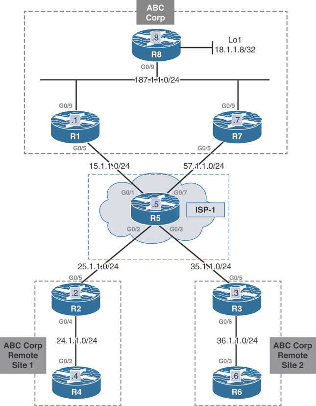
This lab should be conducted on the Enterprise Rack.
Lab Setup:
If you are using EVE-NG, and you have imported the EVE-NG topology from the EVE-NG-Topology folder, ignore the following and use Lab-3-Dual Hub Single Cloud in the DMVPN folder in EVE-NG.
To copy and paste the initial configurations, go to the Initial-config folder ➔ DMVPN folder ➔ Lab-3.
The base topology of the main site has changed to include two VPN routers, R1 and R7. R8, which was originally functioning as a host, has been enabled with IP routing to avoid a common problem with such VPN designs regarding asymmetric routing.
Asymmetric routing is when packets take a different return path from the original path taken to reach the destination. In the example above, R8 sits behind R1 and R7. When R8 receives a packet from R1, it could decide to return that traffic to R7 instead of to R1 again.
Asymmetric routing carries some important consequences. The path through R7 may use a separate set of policies—such as firewall rules, SLAs, and QoS mechanisms—than the R1 path. These differences can cause intermittent or sustained connectivity problems in the network.
To mitigate these issues, R8 has been enabled with routing features, and the R1/R7/R8 LAN will run EIGRP in AS 100. R7 has been configured to advertise a default route to R8, and R1 advertises specific prefixes. This way, R8 will prefer the specific prefixes learned from R1 over the default route from R7. When R1 fails, the specific prefixes are removed, and R8 follows the default route through R7. Below is the configuration for the R1/R7/R8LAN.
On R1:
R1(config)#router eigrp 100 R1(config-router)#network 187.1.1.1 0.0.0.0
On R7:
R7(config)#router eigrp 100 R7(config-router)#network 187.1.1.7 0.0.0.0 R7(config)#interface g0/9 R7(config-if)#ip summary-address eigrp 100 0.0.0.0 0.0.0.0
You should see the following console message:
%DUAL-5-NBRCHANGE: EIGRP-IPv4 100: Neighbor 187.1.1.1
(GigabitEthernet0/9) is up: new adjacency
On R8:
R8(config)#router eigrp 100 R8(config-router)#network 187.1.1.8 0.0.0.0 R8(config-router)#network 18.1.1.8 0.0.0.0
You should see the following console message:
%DUAL-5-NBRCHANGE: EIGRP-IPv4 100: Neighbor 187.1.1.1 (GigabitEthernet0/9) is up: new adjacency %DUAL-5-NBRCHANGE: EIGRP-IPv4 100: Neighbor 187.1.1.7 (GigabitEthernet0/9) is up: new adjacency
On completing the above, the show ip route eigrp 100 command is issued on R8. As seen below, R8 learns an EIGRP default route from R7. Since the rest of the DMVPN has not yet been configured, there are no specific prefixes from R1 at this point:
To verify the configuration:
R8#show ip route eigrp 100 | begin Gate Gateway of last resort is 187.1.1.7 to network 0.0.0.0 D* 0.0.0.0/0 [90/3072] via 187.1.1.7, 00:10:48, GigabitEthernet0/9
This DMVPN design scenario will only discuss Phase 3, since that is the recommended approach to a Dual Hub, Single Cloud design.
Implement Phase 3
Design Goal
ABC Corp has grown into ABC Enterprise, with multiple remote sites in addition to the main site. The corporation has outsourced network design and configuration to a network engineering firm. The firm has been tasked with delivering a design proof of concept for connecting the remote sites to the main site without the added expense of a private WAN circuit. The design should allow remote sites to directly communicate with each other with minimal routing overhead. In addition, a failure of a main site device should not prevent the VPN from functioning. Traffic should flow through R1 primarily and use R7 as backup.
DMVPN Tunnel Configuration
To summarize the design goal stated above, the WAN connectivity design should meet the following criteria:
The VPN solution should use the existing Internet connection to avoid provisioning expensive private WAN circuits.
Remote sites should be able to communicate directly with each other with the least possible routing information overhead.
Failure of a main site device should not prevent the VPN from functioning.
Traffic should be preferred through R1. R7 is used as backup.
These four requirements can be fulfilled using a dual-hub, single-cloud DMVPN configuration. This type of solution obtains high availability, as failure of any one hub device does not impede the functionality of the DMVPN network. In order to allow remote sites to communicate with minimal routing information, DMVPN Phase 3 should be implemented. Phase 3 allows summarization from the hub to the spokes, relying on NHRP redirect messages from the hub to trigger spoke-to-spoke tunnels.
The following configuration is the basic outline configuration for the DMVPN tunnel interfaces for both hubs, R1 and R7, and spokes R2 and R3. Note that each spoke is configured with both hubs as the NHRP NHS, and a single tunnel interface is configured on each device:
On Hub R1:
R1(config)#interface tunnel 100 R1(config-if)#ip address 100.1.1.1 255.255.255.0 R1(config-if)#tunnel source 15.1.1.1 R1(config-if)#tunnel mode gre multipoint R1(config-if)#ip nhrp network-id 100 R1(config-if)#ip nhrp map multicast dynamic R1(config-if)#ip nhrp redirect
On Hub R7:
R7(config)#interface tunnel 100 R7(config-if)#ip address 100.1.1.7 255.255.255.0 R7(config-if)#tunnel source 57.1.1.7 R7(config-if)#tunnel mode gre multipoint R7(config-if)#ip nhrp network-id 100 R7(config-if)#ip nhrp map multicast dynamic R7(config-if)#ip nhrp redirect
On R2:
R2(config)#interface tunnel 100 R2(config-if)#ip address 100.1.1.2 255.255.255.0 R2(config-if)#tunnel source 25.1.1.2 R2(config-if)#tunnel mode gre multipoint R2(config-if)#ip nhrp network-id 100 R2(config-if)#ip nhrp nhs 100.1.1.1 nbma 15.1.1.1 multicast R2(config-if)#ip nhrp nhs 100.1.1.7 nbma 57.1.1.7 multicast R2(config-if)#ip nhrp shortcut
On R3:
R3(config)#interface tunnel 100 R3(config-if)#ip address 100.1.1.3 255.255.255.0 R3(config-if)#tunnel source 35.1.1.3 R3(config-if)#tunnel mode gre multipoint R3(config-if)#ip nhrp network-id 100 R3(config-if)#ip nhrp nhs 100.1.1.1 nbma 15.1.1.1 multicast R3(config-if)#ip nhrp nhs 100.1.1.7 nbma 57.1.1.7 multicast R3(config-if)#ip nhrp shortcut
This configuration enables NHRP redirect and shortcut switching enhancements on the tunnel interfaces for the hubs and spokes, respectively. In addition, on each spoke, the ip nhrp nhs 100.1.1.1 nbma 15.1.1.1 multicast command has been issued for hub R1, and ip nhrp nhs 200.1.1.1 nbma 57.1.1.7 multicast has been issued for hub R7. This allows the spokes to register with both hubs appropriately and use each of them for resolving overlay-to-NBMA mapping information when attempting to form a spoke-to-spoke tunnel.
The show dmvpn output on each router confirms the configuration. Notice in the output below, both spokes have successfully registered with Hub R1 and R7:
On R1:
R1#show dmvpn | begin Peer NBMA
# Ent Peer NBMA Addr Peer Tunnel Add State UpDn Tm Attrb
----- --------------- --------------- ----- -------- -----
1 25.1.1.2 100.1.1.2 UP 00:13:16 D
1 35.1.1.3 100.1.1.3 UP 00:10:01 D
R1#show ip nhrp multicast
I/F NBMA address
Tunnel100 25.1.1.2 Flags: dynamic (Enabled)
Tunnel100 35.1.1.3 Flags: dynamic (Enabled)
On R7:
R7#show dmvpn | begin Peer NBMA
# Ent Peer NBMA Addr Peer Tunnel Add State UpDn Tm Attrb
----- --------------- --------------- ----- -------- -----
1 25.1.1.2 100.1.1.2 UP 00:15:23 D
1 35.1.1.3 100.1.1.3 UP 00:10:16 D
R7#show ip nhrp multicast
I/F NBMA address
Tunnel100 25.1.1.2 Flags: dynamic (Enabled)
Tunnel100 35.1.1.3 Flags: dynamic (Enabled)
On R2:
R2#show dmvpn | begin Peer NBMA
# Ent Peer NBMA Addr Peer Tunnel Add State UpDn Tm Attrb
----- --------------- --------------- ----- -------- -----
1 15.1.1.1 100.1.1.1 UP 00:14:23 S
1 57.1.1.7 100.1.1.7 UP 00:15:59 S
R2#show ip nhrp multicast
I/F NBMA address
Tunnel100 57.1.1.7 Flags: nhs (Enabled)
Tunnel100 15.1.1.1 Flags: nhs (Enabled)
On R3:
R3#show dmvpn | begin Peer NBMA
# Ent Peer NBMA Addr Peer Tunnel Add State UpDn Tm Attrb
----- --------------- --------------- ----- -------- -----
1 15.1.1.1 100.1.1.1 UP 00:11:50 S
1 57.1.1.7 100.1.1.7 UP 00:11:33 S
R3#show ip nhrp multicast
I/F NBMA address
Tunnel100 57.1.1.7 Flags: nhs (Enabled)
Tunnel100 15.1.1.1 Flags: nhs (Enabled)
The output above verifies that the spokes have registered mapping information with both hubs dynamically, just as in the single-hub, single-cloud configuration. Now, whenever the spoke needs to resolve a spoke-to-spoke overlay-to-NBMA mapping, the spokes can use either R1 or R7 to facilitate the resolution process.
The following commands are used to verify reachability between the hub and spokes using a traceroute from R2 to the tunnel 100 address on R1, R7, and R3:
On R2:
R2#traceroute 100.1.1.1 probe 1
Type escape sequence to abort.
Tracing the route to 100.1.1.1
VRF info: (vrf in name/id, vrf out name/id)
1 100.1.1.1 26 msec
R2#traceroute 100.1.1.7 probe 1
Type escape sequence to abort.
Tracing the route to 100.1.1.7
VRF info: (vrf in name/id, vrf out name/id)
1 100.1.1.7 22 msec
R2#traceroute 100.1.1.3 probe 1
Type escape sequence to abort.
Tracing the route to 100.1.1.3
VRF info: (vrf in name/id, vrf out name/id)
1 100.1.1.1 12 msec
2 100.1.1.3 52 msec
R2#traceroute 100.1.1.3 probe 1
Type escape sequence to abort.
Tracing the route to 100.1.1.3
VRF info: (vrf in name/id, vrf out name/id)
1 100.1.1.3 4 msec
R2#show dmvpn | begin Peer NBMA
# Ent Peer NBMA Addr Peer Tunnel Add State UpDn Tm Attrb
----- --------------- --------------- ----- -------- -----
1 15.1.1.1 100.1.1.1 UP 00:23:36 S
1 35.1.1.3 100.1.1.3 UP 00:01:06 D
1 57.1.1.7 100.1.1.7 UP 00:25:12 S
The next sections detail routing protocol configuration for EIGRP and BGP for this design. OSPF is not demonstrated because it is unable to fully meet the requirement of minimal routing information. OSPF’s requirement that all routers in the same area must have all routes reachable within the area limits the ability to completely summarize routing information from the hub routers to the spokes.
Implement EIGRP
The EIGRP configuration here is very similar to the single-hub, single-cloud configuration. EIGRP is enabled on all tunnel interfaces in the network as well as the connected LAN interface of each router. R1 and R7 are configured to send a default route down to the spokes out their tunnel 100 interfaces as well. The following are the initial configurations for EIGRP as the DMVPN overlay:
On R1:
R1(config)#router eigrp 100 R1(config-router)#network 100.1.1.1 0.0.0.0 R1(config)#interface tunnel 100 R1(config-if)#ip summary-address eigrp 100 0.0.0.0 0.0.0.0
On R7:
R7(config)#router eigrp 100 R7(config-router)#network 100.1.1.7 0.0.0.0 R7(config)#interface tunnel 100 R7(config-if)#ip summary-address eigrp 100 0.0.0.0 0.0.0.0
Due to the lack of NHRP multicast mappings for each other, the hub routers R1 and R7 will not become EIGRP neighbors.
R7#show ip nhrp 100.1.1.1 R7#
On R2:
R2(config)#router eigrp 100 R2(config-router)#network 24.1.1.2 0.0.0.0 R2(config-router)#network 100.1.1.2 0.0.0.0 R2(config-router)#passive-interface g0/4
You should see the following console messages:
%DUAL-5-NBRCHANGE: EIGRP-IPv4 100: Neighbor 100.1.1.1 (Tunnel100) is up: new adjacency %DUAL-5-NBRCHANGE: EIGRP-IPv4 100: Neighbor 100.1.1.7 (Tunnel100) is up: new adjacency
On R3:
R3(config)#router eigrp 100 R3(config-router)#network 36.1.1.3 0.0.0.0 R3(config-router)#network 100.1.1.3 0.0.0.0 R3(config-router)#passive-interface g0/6
You should see the following console messages:
%DUAL-5-NBRCHANGE: EIGRP-IPv4 100: Neighbor 100.1.1.1 (Tunnel100) is up: new adjacency %DUAL-5-NBRCHANGE: EIGRP-IPv4 100: Neighbor 100.1.1.7 (Tunnel100) is up: new adjacency
With the console log messages above confirming the EIGRP neighborships between the spokes and hub routers, the show ip route eigrp 100 command is issued on R2 and R3. Both spokes are performing ECMP and have installed the default route advertised by both hubs:
On R2:
R2#show ip route eigrp 100 | begin Gate
Gateway of last resort is 100.1.1.7 to network 0.0.0.0
D* 0.0.0.0/0 [90/26880256] via 100.1.1.7, 00:03:45, Tunnel100
[90/26880256] via 100.1.1.1, 00:03:45, Tunnel100
On R3:
R3#show ip route eigrp 100 | begin Gate
Gateway of last resort is 100.1.1.7 to network 0.0.0.0
D* 0.0.0.0/0 [90/26880256] via 100.1.1.7, 00:02:11, Tunnel100
[90/26880256] via 100.1.1.1, 00:02:11, Tunnel100
R8’s routing table reveals the specific prefixes learned from R1 via EIGRP:
R8#show ip route eigrp | begin Gate
Gateway of last resort is 187.1.1.7 to network 0.0.0.0
D* 0.0.0.0/0 [90/3072] via 187.1.1.7, 00:09:59, GigabitEthernet0/9
24.0.0.0/24 is subnetted, 1 subnets
D 24.1.1.0 [90/26880512] via 187.1.1.1, 00:06:11,
GigabitEthernet0/9
36.0.0.0/24 is subnetted, 1 subnets
D 36.1.1.0 [90/26880512] via 187.1.1.1, 00:04:07,
GigabitEthernet0/9
100.0.0.0/24 is subnetted, 1 subnets
D 100.1.1.0 [90/26880256] via 187.1.1.1, 00:11:15,
GigabitEthernet0/9
As shown here, R8 retains a default route it received from R7 originally in addition to the specific prefixes from R1. R8 will always prefer the specific prefixes from R1 over the EIGRP default route from R7, preventing the asymmetric routing situation described in the base configuration section.
The design goals specify that R1 should be used as the primary path, and R7 should be backup. To configure the network to comply with this restriction, an offset list is configured in the EIGRP configuration of R7 that adds the delay setting 500 to all prefixes advertised out the tunnel 100 interface. As a result, R2 and R3 now install the default route received from R1 only:
On R7:
R7(config)#router eigrp 100 R7(config-router)#offset-list 0 out 500 tunnel100
To verify the configuration:
On R2:
R2#show ip route eigrp 100 | begin Gate Gateway of last resort is 100.1.1.1 to network 0.0.0.0 D* 0.0.0.0/0 [90/26880256] via 100.1.1.1, 00:01:09, Tunnel100
On R3:
R3#show ip route eigrp 100 | begin Gate Gateway of last resort is 100.1.1.1 to network 0.0.0.0 D* 0.0.0.0/0 [90/26880256] via 100.1.1.1, 00:01:39, Tunnel100
When this configuration is complete, the following traceroute outputs confirm that the network functions as described in the design goals section. A traceroute from R4 to 18.1.1.8 is shown traversing the hub R1. The first traceroute from R4 to R6 traverses the hub while the NHRP resolution process completes. The subsequent traceroute is shown taking the direct spoke-to-spoke tunnel between R2 and R3.
On R4:
R4#traceroute 18.1.1.8 probe 1 Type escape sequence to abort. Tracing the route to 18.1.1.8 VRF info: (vrf in name/id, vrf out name/id) 1 24.1.1.2 46 msec 2 100.1.1.1 8 msec 3 187.1.1.8 12 msec R4#traceroute 36.1.1.6 probe 1 Type escape sequence to abort. Tracing the route to 36.1.1.6 VRF info: (vrf in name/id, vrf out name/id) 1 24.1.1.2 3 msec 2 100.1.1.1 6 msec 3 100.1.1.3 66 msec 4 36.1.1.6 20 msec R4#traceroute 36.1.1.6 probe 1 Type escape sequence to abort. Tracing the route to 36.1.1.6 VRF info: (vrf in name/id, vrf out name/id) 1 24.1.1.2 2 msec 2 100.1.1.3 7 msec 3 36.1.1.6 9 msec
The next step is to verify that network redundancy functions as described in the design goals.
Since the DMVPN solution is configured in Phase 3, spoke-to-spoke tunnels that are formed before the hub fails will continue to function. In this case, failure of the hub prevents new spoke-to-spoke tunnels from being formed. To simulate this situation in the topology, the tunnel 100 interface on R1 is shut down. In addition, the clear ip nhrp command is issued on R2 and R3 to clear the dynamic NHRP entries from the NHRP mapping tables:
On R1:
R1(config)#interface tunnel 100
R1(config-if)#shut
On R2:
R2#show dmvpn | begin Peer NBMA
# Ent Peer NBMA Addr Peer Tunnel Add State UpDn Tm Attrb
----- --------------- --------------- ----- -------- -----
2 35.1.1.3 100.1.1.3 UP 00:03:14 DT1
100.1.1.3 UP 00:03:14 DT1
1 15.1.1.1 100.1.1.1 UP 03:40:42 S
1 57.1.1.7 100.1.1.7 UP 03:42:18 S
R2#clear ip nhrp
R2#show dmvpn | b Peer NBMA
# Ent Peer NBMA Addr Peer Tunnel Add State UpDn Tm Attrb
----- --------------- --------------- ----- -------- -----
1 15.1.1.1 100.1.1.1 UP 03:41:55 S
1 57.1.1.7 100.1.1.7 UP 03:43:31 S
On R3:
R3#clear ip nhrp
With the NHRP mappings cleared, R2 and R3 need to reestablish the spoke-to-spoke tunnel between them. In Phase 3, the spoke-to-spoke tunnel is triggered by the hub. After R1 fails, R2 and R3 install the default route from R7 in their routing tables. The first traceroute packet will now go to R7, which will initiate the NHRP redirect process and trigger the R2/R3 spoke-to-spoke tunnel formation:
On R2:
R2#show ip rou eigrp 100 | begin Gate Gateway of last resort is 100.1.1.7 to network 0.0.0.0 D* 0.0.0.0/0 [90/26880756] via 100.1.1.7, 00:02:29, Tunnel100 R3#show ip route eigrp 100 | begin Gate Gateway of last resort is 100.1.1.7 to network 0.0.0.0 D* 0.0.0.0/0 [90/26880756] via 100.1.1.7, 00:03:07, Tunnel100
On R4:
R4#traceroute 18.1.1.8 probe 1 Type escape sequence to abort. Tracing the route to 18.1.1.8 VRF info: (vrf in name/id, vrf out name/id) 1 24.1.1.2 16 msec 2 100.1.1.7 13 msec 3 187.1.1.8 15 msec R4#traceroute 36.1.1.6 probe 1 Type escape sequence to abort. Tracing the route to 36.1.1.6 VRF info: (vrf in name/id, vrf out name/id) 1 24.1.1.2 4 msec 2 100.1.1.7 8 msec 3 100.1.1.3 11 msec 4 36.1.1.6 13 msec R4#traceroute 36.1.1.6 probe 1 Type escape sequence to abort. Tracing the route to 36.1.1.6 VRF info: (vrf in name/id, vrf out name/id) 1 24.1.1.2 17 msec 2 100.1.1.3 9 msec 3 36.1.1.6 15 msec
After confirming the failover, the proof of concept prototype has been implemented successfully, using EIGRP as the overlay routing protocol.
Implement iBGP
The configuration for iBGP as the overlay routing protocol again mimics the single-hub, single-cloud configuration. The difference now is that both R1 and R7 will become route reflectors for the DMVPN spoke routers. Both R1 and R7 are also configured to send a default route down to the spokes through BGP.
The configuration below recreates the BGP peer group for dynamic peering on R1 and R7. It also includes modifications for the default BGP timers to facilitate faster neighbor down detection.
The spokes R2 and R3 are configured to peer with both R1 and R7. Their connected host networks are advertised into BGP with the network command. To implement path preference, the spokes are preloaded to apply a local preference of 150 to all paths learned from R1. Setting the local preference to 150 ensures the spokes will prefer R1’s path over R7’s as required by the design goals.
On R1:
R1(config)#no router eigrp 100
R1(config)#interface tunnel 100
R1(config-if)#no shut
R1(config)#ip prefix-list TST permit 0.0.0.0/0
R1(config)#route-map default permit 10
R1(config-route-map)#match ip addr prefix TST
R1(config)#router bgp 100
R1(config-router)#neighbor spokes peer-group
R1(config-router)#neighbor spokes remote-as 100
R1(config-router)#neighbor spokes timers 6 20
R1(config-router)#bgp listen range 100.1.1.0/24 peer-group spokes
R1(config-router)#address-family ipv4
R1(config-router-af)#neighbor spokes route-reflector-client
R1(config-router-af)#neighbor spokes default-originate
R1(config-router-af)#neighbor spokes route-map default out
On R7:
R7(config)#no router eigrp 100
R7(config)#ip prefix-list TST permit 0.0.0.0/0
R7(config)#route-map default permit 10
R7(config-route-map)#match ip address prefix-list TST
R7(config)#router bgp 100
R7(config-router)#neighbor spokes peer-group
R7(config-router)#neighbor spokes remote 100
R7(config-router)#neighbor spokes timers 6 20
R7(config-router)#bgp listen range 100.1.1.0/24 peer-group spokes
R7(config-router)#address-family ipv4
R7(config-router-af)#neighbor spokes route-reflector-client
R7(config-router-af)#neighbor spokes route-map default out
R7(config-router-af)#neighbor spokes default-originate
On R2:
R2(config)#no router eigrp 100
R2(config)#route-map local-pref permit 10
R2(config-route-map)#set local-preference 150
R2(config)#router bgp 100
R2(config-router)#neighbor 100.1.1.1 remote-as 100
R2(config-router)#neighbor 100.1.1.7 remote-as 100
R2(config-router)#address-family ipv4
R2(config-router-af)#network 24.1.1.0 mask 255.255.255.0
R2(config-router-af)#neighbor 100.1.1.1 route-map local-pref in
R2#clear ip bgp * in
You should see the following console messages:
%BGP-5-ADJCHANGE: neighbor 100.1.1.1 Up %BGP-5-ADJCHANGE: neighbor 100.1.1.7 Up
On R3:
R3(config)#no router eigrp 100
R3(config)#route-map local-pref permit 10
R3(config-route-map)#set local-preference 150
R3(config)#router bgp 100
R3(config-router)#neighbor 100.1.1.1 remote-as 100
R3(config-router)#neighbor 100.1.1.7 remote-as 100
R3(config-router)#address-family ipv4
R3(config-router-af)#neighbor 100.1.1.1 route-map local-pref in
R3(config-router-af)#network 36.1.1.0 mask 255.255.255.0
R3#clear ip bgp * in
You should see the following console messages:
%BGP-5-ADJCHANGE: neighbor 100.1.1.1 Up %BGP-5-ADJCHANGE: neighbor 100.1.1.7 Up
After the iBGP peerings are formed between the hub and spoke routers, R2 and R3’s BGP table shows the two default routes. The default route from R1 is selected as best because of the higher local preference value of 150 when compared to the default local preference value 100 from R7:
On R2:
R2#show ip bgp | begin Net
Network Next Hop Metric LocPrf Weight Path
* i 0.0.0.0 100.1.1.7 0 100 0 i
*>i 100.1.1.1 0 150 0 i
*> 24.1.1.0/24 0.0.0.0 0 32768 i
R2#show ip route bgp | begin Gate
Gateway of last resort is 100.1.1.1 to network 0.0.0.0
B* 0.0.0.0/0 [200/0] via 100.1.1.1, 00:09:04
On R3:
R3#show ip bgp | begin Net
Network Next Hop Metric LocPrf Weight Path
* i 0.0.0.0 100.1.1.7 0 100 0 i
*>i 100.1.1.1 0 150 0 i
*> 36.1.1.0/24 0.0.0.0 0 32768 i
R3#show ip route bgp | begin Gate
Gateway of last resort is 100.1.1.1 to network 0.0.0.0
B* 0.0.0.0/0 [200/0] via 100.1.1.1, 00:05:06
To provide proper connectivity to R8, R1 is also configured to redistribute BGP prefixes into EIGRP using the redistribute bgp command under the EIGRP configuration mode.
BGP must also be configured to allow iBGP prefixes to be redistributed into an IGP. This is done using the bgp redistribute-internal command configured on R1 under the BGP configuration mode. R7 will continue to provide reachability to R8 via the EIGRP default route:
On R1:
R1(config)#router bgp 100 R1(config-router)#address-family ipv4 R1(config-router-af)#bgp redistribute-internal R1(config)#router eigrp 100 R1(config-router)#network 187.1.1.1 0.0.0.0 R1(config-router)#redistribute bgp 100 metric 1 1 1 1 1
On R7:
R7(config)#router eigrp 100 R7(config-router)#network 187.1.1.7 0.0.0.0 R7(config-router)#interface g0/9 R7(config-if)#ip summary-address eigrp 100 0.0.0.0 0.0.0.0
On R8:
Following configuration from R8 has been retained from the earlier task:
R8(config)#router eigrp 100
R8(config-router)#network 187.1.1.8 0.0.0.0
R8(config-router)#network 18.1.1.8 0.0.0.0
R8#show ip route | begin Gate
Gateway of last resort is 187.1.1.7 to network 0.0.0.0
D* 0.0.0.0/0 [90/3072] via 187.1.1.7, 00:01:56, GigabitEthernet0/9
18.0.0.0/32 is subnetted, 1 subnets
C 18.1.1.8 is directly connected, Loopback1
24.0.0.0/24 is subnetted, 1 subnets
D EX 24.1.1.0 [170/2560000512] via 187.1.1.1, 00:00:22,
GigabitEthernet0/9
36.0.0.0/24 is subnetted, 1 subnets
D EX 36.1.1.0 [170/2560000512] via 187.1.1.1, 00:00:22,
GigabitEthernet0/9
187.1.0.0/16 is variably subnetted, 2 subnets, 2 masks
C 187.1.1.0/24 is directly connected, GigabitEthernet0/9
L 187.1.1.8/32 is directly connected, GigabitEthernet0/9
After this configuration, R8 again chooses the specific prefixes over the default route received from R7. Much as in the EIGRP section, redundancy is confirmed by shutting down the tunnel 100 interface on R1, resulting in the spokes using the default route from R7. The dynamic NHRP mapping entries are cleared on R2 and R3 with the clear ip nhrp command. Following this, traceroute from R4 to R6 confirms Hub R7 as the active hub in use:
On R1:
R1(config)#interface tunnel 100 R1(config-if)#shut
On R2:
R2#show ip bgp | begin Net
Network Next Hop Metric LocPrf Weight Path
*>i 0.0.0.0 100.1.1.7 0 100 0 i
*> 24.1.1.0/24 0.0.0.0 0 32768 i
On R2 and R3:
Rx#clear ip nhrp
On R3:
R3#show ip route bgp | begin Gate Gateway of last resort is 100.1.1.7 to network 0.0.0.0 B* 0.0.0.0/0 [200/0] via 100.1.1.7, 00:00:49
Traceroute from R4 to R8’s loopback address uses Hub R7. Traceroute to the remote spoke network from R4 first transits over Hub R7. Subsequent traceroute is shown to use the spoke-to-spoke tunnel between R2 and R3:
On R4:
R4#traceroute 18.1.1.8 probe 1 Type escape sequence to abort. Tracing the route to 18.1.1.8 VRF info: (vrf in name/id, vrf out name/id) 1 24.1.1.2 13 msec 2 100.1.1.7 8 msec 3 187.1.1.8 15 msec R4#traceroute 36.1.1.6 probe 1 Type escape sequence to abort. Tracing the route to 36.1.1.6 VRF info: (vrf in name/id, vrf out name/id) 1 24.1.1.2 14 msec 2 100.1.1.7 8 msec 3 100.1.1.3 19 msec 4 36.1.1.6 20 msec R4#traceroute 36.1.1.6 probe 1 Type escape sequence to abort. Tracing the route to 36.1.1.6 VRF info: (vrf in name/id, vrf out name/id) 1 24.1.1.2 3 msec 2 100.1.1.3 6 msec 3 36.1.1.6 13 msec
Implement eBGP
Finally, the eBGP configuration once again mimics the configuration in the single-hub, dual-cloud configuration. BGP can again be configured such that all spokes are configured to be in the same AS or different autonomous systems. Here we outline the configuration steps for both methods, where the path engineering steps are the same for the two methods.
Spokes in the Same AS
If the spokes are members of the same AS, the peer group configuration for the BGP listen range should set the remote AS to the spoke AS. Notice that there is no need to issue the allowas-in command on the spokes. The spokes will not receive each other’s prefixes through BGP because the hubs are sending a default route down to the spokes. When the spoke-to-spoke tunnel is formed, an NHRP route is installed that does not carry the AS path information. The following commands configure BGP on R1, R7, R2, and R3 for same AS DMVPN Phase 3 operation:
On R1:
R1(config-router)#interface tunnel 100 R1(config-if)#no shut R1(config)#router bgp 100 R1(config-router)#no neighbor spokes remote-as 100 R1(config-router)#no neighbor spokes route-reflector-client R1(config-router)#neighbor spokes remote-as 230
On R7:
R7(config)#router bgp 100 R7(config-router)#no neighbor spokes remote 100 R7(config-router)#no neighbor spokes route-reflector-client R7(config-router)#neighbor spokes remote-as 230
On R2:
R2(config)#no router bgp 100
The route-map local-pref from the previous section was not removed and is therefore used in this configuration:
R2(config)#router bgp 230 R2(config-router)#neighbor 100.1.1.1 remote 100 R2(config-router)#neighbor 100.1.1.7 remote 100 R2(config-router)#address-family ipv4 R2(config-router-af)#network 24.1.1.0 mask 255.255.255.0 R2(config-router-af)#neighbor 100.1.1.1 route-map local-pref in
On R3:
R3(config)#no router bgp 100
NOTE: The route-map local-pref from the previous section was not removed and is therefore used in this configuration:
R3(config)#router bgp 230 R3(config-router)#neighbor 100.1.1.1 remote-as 100 R3(config-router)#neighbor 100.1.1.7 remote-as 100 R3(config-router)#address-family ipv4 R3(config-router-af)#network 36.1.1.0 mask 255.255.255.0 R3(config-router-af)#neighbor 100.1.1.1 route-map local-pref in R3#clear ip bgp * in
Here, local preference is once again modified on the spoke side to prefer R1’s paths over R7’s. After the configurations have been entered and the peerings come up, R2’s and R3’s routing tables reflect the preferences. The resulting BGP tables on R2 and R3 are as follows:
On R2:
R2#show ip bgp | begin Net
Network Next Hop Metric LocPrf Weight Path
*> 0.0.0.0 100.1.1.1 150 0 100 i
* 100.1.1.7 0 100 i
*> 24.1.1.0/24 0.0.0.0 0 32768 i
On R3:
R3#show ip bgp | begin Net
Network Next Hop Metric LocPrf Weight Path
*> 0.0.0.0 100.1.1.1 150 0 100 i
* 100.1.1.7 0 100 i
*> 36.1.1.0/24 0.0.0.0 0 32768 i
Spokes in Different Autonomous Systems
With the spokes in different autonomous systems, the major configuration change that must be made is on the individual spokes and on the peer group configuration on the hub routers. First, the peer group needs to include the additional spoke ASNs via the alternate-as command. The spoke BGP processes need to be configured with the proper ASN as well.
After that configuration, the same path engineering mechanic—modifying the local preference on the spokes is implemented to drive path preference:
On R1:
R1(config)#router bgp 100
R1(config-router)#no neighbor spokes remote-as 230
R1(config-router)#neighbor spokes remote-as 200 alternate-as 300
On R7:
R7(config)#router bgp 100
R7(config-router)#no neighbor spokes remote-as 230
R7(config-router)#neighbor spokes remote 200 alternate-as 300
On R2:
R2(config)#no router bgp 230
R2(config)#router bgp 200
R2(config-router)#bgp log-neighbor-changes
R2(config-router)#neighbor 100.1.1.1 remote-as 100
R2(config-router)#neighbor 100.1.1.7 remote-as 100
R2(config-router)#address-family ipv4
R2(config-router-af)#network 24.1.1.0 mask 255.255.255.0
R2(config-router-af)#neighbor 100.1.1.1 route-map local-pref in
You should see the following console messages:
%BGP-5-ADJCHANGE: neighbor 100.1.1.7 Up %BGP-5-ADJCHANGE: neighbor 100.1.1.1 Up
On R3:
R3(config)#no router bgp 230
R3(config)#router bgp 300
R3(config-router)#neighbor 100.1.1.1 remote-as 100
R3(config-router)#neighbor 100.1.1.7 remote-as 100
R3(config-router)#address-family ipv4
R3(config-router-af)#network 36.1.1.0 mask 255.255.255.0
R3(config-router-af)#neighbor 100.1.1.1 route-map local-pref in
You should see the following console messages:
%BGP-5-ADJCHANGE: neighbor 100.1.1.7 Up %BGP-5-ADJCHANGE: neighbor 100.1.1.1 Up
After the configurations above are applied, the BGP tables on R2 and R3 reflect R1’s path for the default route as the chosen best path.
On R2:
R2#show ip bgp | begin Net
Network Next Hop Metric LocPrf Weight Path
*> 0.0.0.0 100.1.1.1 150 0 100 i
* 100.1.1.7 0 100 i
*> 24.1.1.0/24 0.0.0.0 0 32768 i
R2#show ip route bgp | begin Gate
Gateway of last resort is 100.1.1.1 to network 0.0.0.0
B* 0.0.0.0/0 [20/0] via 100.1.1.1, 00:07:01
On R3:
R3#show ip bgp | begin Net
Network Next Hop Metric LocPrf Weight Path
* 0.0.0.0 100.1.1.7 0 100 i
*> 100.1.1.1 150 0 100 i
*> 36.1.1.0/24 0.0.0.0 0 32768 i
R3#show ip route bgp | begin Gate
Gateway of last resort is 100.1.1.1 to network 0.0.0.0
B* 0.0.0.0/0 [20/0] via 100.1.1.1, 00:05:40
BGP should be redistributed into EIGRP 100 for reachability. This configuration has already been performed in an earlier task. Notice the output from R8 below. It has a EIGRP default route from R7 and specific BGP prefixes for the remote LAN networks from R1:
On R8:
R8#show ip route eigrp 100 | begin Gate
Gateway of last resort is 187.1.1.7 to network 0.0.0.0
D* 0.0.0.0/0 [90/3072] via 187.1.1.7, 01:24:20, GigabitEthernet0/9
24.0.0.0/24 is subnetted, 1 subnets
D EX 24.1.1.0 [170/2560000512] via 187.1.1.1, 00:12:15,
GigabitEthernet0/9
36.0.0.0/24 is subnetted, 1 subnets
D EX 36.1.1.0 [170/2560000512] via 187.1.1.1, 00:09:42,
GigabitEthernet0/9
When routing to the destination remote networks, R8 will always choose the specific path from R1 over the default route from R7.
The traceroute outputs below verifies connectivity between the remote networks. A traceroute to 18.1.1.8 from R4 is sent to R1. Traffic from R4 to the remote network on R6 first traverses the hub R1. Subsequent traceroutes show this traffic using the spoke-to-spoke tunnel between R2 and R3:
On R4:
R4#traceroute 18.1.1.8 probe 1 Type escape sequence to abort. Tracing the route to 18.1.1.8 VRF info: (vrf in name/id, vrf out name/id) 1 24.1.1.2 15 msec 2 100.1.1.1 7 msec 3 187.1.1.8 12 msec R4#traceroute 36.1.1.6 probe 1 Type escape sequence to abort. Tracing the route to 36.1.1.6 VRF info: (vrf in name/id, vrf out name/id) 1 24.1.1.2 3 msec 2 100.1.1.1 6 msec 3 100.1.1.3 18 msec 4 36.1.1.6 20 msec R4#traceroute 36.1.1.6 probe 1 Type escape sequence to abort. Tracing the route to 36.1.1.6 VRF info: (vrf in name/id, vrf out name/id) 1 24.1.1.2 5 msec 2 100.1.1.3 6 msec 3 36.1.1.6 10 msec
For both design cases (Spokes in the same AS or in different AS), redundancy is confirmed by shutting down the tunnel 100 interface on R1. A clear ip nhrp is issued on R2 and R3. Following this, traceroutes between remote networks verify the use of Hub R7:
On R1:
R1(config)#interface tunnel 100 R1(config-if)#shut
On R2 and R3:
Rx#clear ip nhrp
On R2:
R2#show ip bgp | begin Net
Network Next Hop Metric LocPrf Weight Path
*> 0.0.0.0 100.1.1.7 0 100 i
*> 24.1.1.0/24 0.0.0.0 0 32768 i
On R3:
R3#show ip bgp | begin Net
Network Next Hop Metric LocPrf Weight Path
*> 0.0.0.0 100.1.1.7 0 100 i
*> 36.1.1.0/24 0.0.0.0 0 32768 i
R4#traceroute 18.1.1.8 probe 1
Type escape sequence to abort.
Tracing the route to 18.1.1.8
VRF info: (vrf in name/id, vrf out name/id)
1 24.1.1.2 1 msec
2 100.1.1.7 2 msec
3 187.1.1.8 3 msec
R4#traceroute 36.1.1.6 probe 1
Type escape sequence to abort.
Tracing the route to 36.1.1.6
VRF info: (vrf in name/id, vrf out name/id)
1 24.1.1.2 1 msec
2 100.1.1.7 2 msec
3 100.1.1.3 3 msec
4 36.1.1.6 7 msec
R4#traceroute 36.1.1.6 probe 1
Type escape sequence to abort.
Tracing the route to 36.1.1.6
VRF info: (vrf in name/id, vrf out name/id)
1 24.1.1.2 1 msec
2 100.1.1.3 2 msec
3 36.1.1.6 3 msec
Lab 4: Dual Hub, Dual Cloud
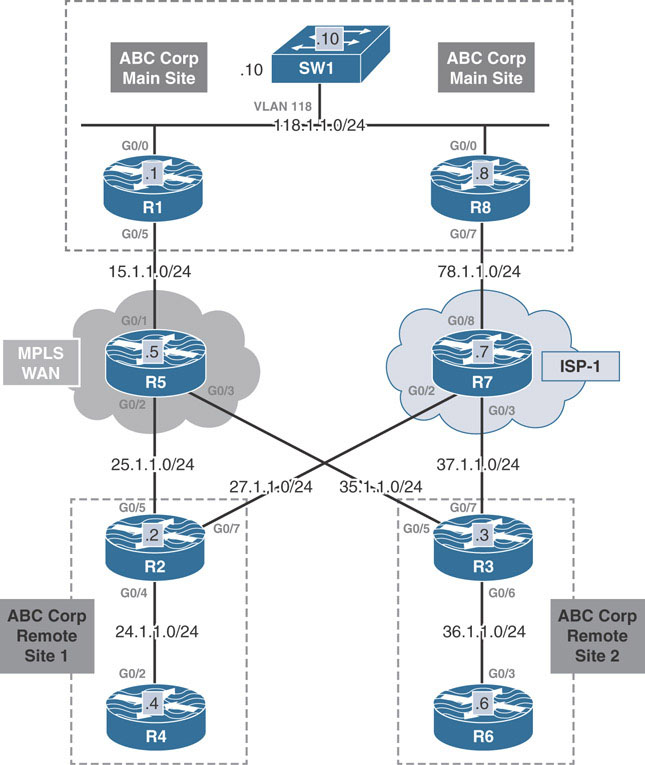
This lab should be conducted on the Enterprise Rack.
Lab Setup:
If you are using EVE-NG, and you have imported the EVE-NG topology from the EVE-NG-Topology folder, ignore the following and use Lab-4-Dual Hub Dual Cloud in the DMVPN folder in EVE-NG.
To copy and paste the initial configurations, go to the Initial-config folder → DMVPN folder → Lab-4.
As with the base configuration in the dual-hub, single-cloud section, the LAN at the main site now includes three devices (R1, R8, SW1) connected to the same LAN interface, as shown in the diagram above.
To prevent asymmetric routing issues that could interfere with efficient routing, EIGRP is once again run on the LAN. R1 advertises specific prefixes, using redistribution if necessary, and R8 advertises a default summary route. SW1 chooses the more specific route through R1 (the MPLS-WAN connection) if R1 is advertising the specific prefixes. If R1’s tunnel 100 fails, it withdraws its specific prefix, leaving the default route through R8.
The configuration below sets up this basic routing:
On R1:
R1(config)#router eigrp 100 R1(config-router)#network 118.1.1.1 0.0.0.0
On R8:
R8(config)#router eigrp 100 R8(config-router)#network 118.1.1.8 0.0.0.0
You should see the following console message:
%DUAL-5-NBRCHANGE: EIGRP-IPv4 100: Neighbor 118.1.1.1
(GigabitEthernet0/0) is up: new adjacency
R8(config)#interface g0/0
R8(config-if)#ip summary-address eigrp 100 0.0.0.0 0.0.0.0
On SW1:
SW1(config)#router eigrp 100 SW1(config-router)#network 118.1.1.10 0.0.0.0 SW1(config-router)#network 18.1.1.8 0.0.0.0
You should see the following console messages:
%DUAL-5-NBRCHANGE: EIGRP-IPv4 100: Neighbor 118.1.1.1 (Vlan118) is up: new adjacency %DUAL-5-NBRCHANGE: EIGRP-IPv4 100: Neighbor 118.1.1.8 (Vlan118) is up: new adjacency
The routing table from SW1 is shown below. Since routing hasn’t been established over DMVPN yet, the only EIGRP route SW1 learns is the default route from R8:
To verify the configuration:
SW1#show ip route eigrp 100 | begin Gate Gateway of last resort is 118.1.1.8 to network 0.0.0.0 D* 0.0.0.0/0 [90/3072] via 118.1.1.8, 00:02:44, Vlan118
Implement Phase 3
Design Goal
After reviewing the previous proposal, ABC Corp, based on its previous experience, questions the network design firm on the reliability of a single Internet connection for transport between the organization’s sites. ABC asks for an additional proof of concept for an MPLS WAN circuit as a primary path and the Internet connection as a backup path. The same requirements of site-to-site connectivity are also applied to this design.
DMVPN Tunnel Configuration
The design goal above expands on the previous design goal by adding an additional ISP transport to the design proposal from the dual-hub, single-cloud configuration. The requirements are the same except that now, each hub will represent a separate DMVPN cloud connected to a specific ISP connection—in order to provide both transport and hub redundancy.
All the other requirements of direct spoke-to-spoke communication and simplified routing tables apply to this design goal as well. DMVPN Phase 3 will be implemented using EIGRP and BGP. OSPF will not be used due to the limitation of summarization from the hub to the spokes.
Below is the proposed configuration for the DMVPN Phase 3. R1 connects solely to the MPLS WAN circuit, and R8 connects solely to ISP-1. R2 and R3 are dual connected, with a single interface toward each transport. Tunnel 100 is configured on R1, R2, and R3 using source IP addresses from the MPLS WAN circuit and network ID 100. Tunnel 200 is configured on R8, R2, and R3 using source IP addresses from ISP-1 and network ID 200.
On Hub R1:
R1(config)#interface tunnel 100 R1(config-if)#ip address 100.1.1.1 255.255.255.0 R1(config-if)#tunnel source 15.1.1.1 R1(config-if)#tunnel mode gre multipoint R1(config-if)#ip nhrp network-id 100 R1(config-if)#ip nhrp map multicast dynamic R1(config-if)#ip nhrp redirect
On Hub R8:
R8(config)#interface tunnel 200 R8(config-if)#ip address 200.1.1.8 255.255.255.0 R8(config-if)#tunnel source 78.1.1.8 R8(config-if)#tunnel mode gre multipoint R8(config-if)#ip nhrp network-id 200 R8(config-if)#ip nhrp map multicast dynamic R8(config-if)#ip nhrp redirect
On R2:
R2(config)#interface tunnel 100 R2(config-if)#ip address 100.1.1.2 255.255.255.0 R2(config-if)#tunnel source 25.1.1.2 R2(config-if)#tunnel mode gre multipoint R2(config-if)#ip nhrp network-id 100 R2(config-if)#ip nhrp nhs 100.1.1.1 nbma 15.1.1.1 multicast R2(config-if)#ip nhrp shortcut R2(config)#interface tunnel 200 R2(config-if)#ip address 200.1.1.2 255.255.255.0 R2(config-if)#tunnel source 27.1.1.2 R2(config-if)#tunnel mode gre multipoint R2(config-if)#ip nhrp network-id 200 R2(config-if)#ip nhrp nhs 200.1.1.8 nbma 78.1.1.8 multicast R2(config-if)#ip nhrp shortcut
On R3:
R3(config)#interface tunnel 100 R3(config-if)#ip address 100.1.1.3 255.255.255.0 R3(config-if)#tunnel source 35.1.1.3 R3(config-if)#tunnel mode gre multipoint R3(config-if)#ip nhrp network-id 100 R3(config-if)#ip nhrp nhs 100.1.1.1 nbma 15.1.1.1 multicast R3(config-if)#ip nhrp shortcut R3(config)#interface tunnel 200 R3(config-if)#ip address 200.1.1.3 255.255.255.0 R3(config-if)#tunnel source 37.1.1.3 R3(config-if)#tunnel mode gre multipoint R3(config-if)#ip nhrp network-id 200 R3(config-if)#ip nhrp nhs 200.1.1.8 nbma 78.1.1.8 multicast R3(config-if)#ip nhrp shortcut
To verify the configuration:
The following verifies the state of the tunnels on the hub routers. As seen below, both spokes have successfully registered with the hubs R1 and R8:
On R1:
R1#show dmvpn | begin Peer NBMA
# Ent Peer NBMA Addr Peer Tunnel Add State UpDn Tm Attrb
----- --------------- --------------- ----- -------- -----
1 25.1.1.2 100.1.1.2 UP 00:08:10 D
1 35.1.1.3 100.1.1.3 UP 00:03:21 D
On R8:
R8#show dmvpn | begin Peer NBMA
# Ent Peer NBMA Addr Peer Tunnel Add State UpDn Tm Attrb
----- --------------- --------------- ----- -------- -----
1 27.1.1.2 200.1.1.2 UP 00:06:28 D
1 37.1.1.3 200.1.1.3 UP 00:02:31 D
Implement EIGRP
At this point in the guided lab, the basic EIGRP configuration for Phase 3 DMVPN has been well established. The same configuration principles applied to the previous versions all apply to this design as well. EIGRP should be configured on all tunnel interfaces with the same EIGRP ASN. The hubs R1 and R8 should be configured to send a summary default route down to the spokes out their tunnel 100 and tunnel 200 interfaces. Host networks at the remote site are also advertised into EIGRP 100 with the network command. The LAN interfaces are declared as passive interfaces under the EIGRP configuration mode:
On R1:
R1(config)#router eigrp 100 R1(config-router)#network 100.1.1.1 0.0.0.0 R1(config)#interface tunnel 100 R1(config-if)#ip summary-address eigrp 100 0.0.0.0 0.0.0.0
On R8:
R8(config)#router eigrp 100 R8(config-router)#network 200.1.1.8 0.0.0.0 R8(config)#interface tunnel 200 R8(config-if)#ip summary-address eigrp 100 0.0.0.0 0.0.0.0
On R2:
R2(config)#router eigrp 100 R2(config-router)#network 24.1.1.2 0.0.0.0 R2(config-router)#network 100.1.1.2 0.0.0.0 R2(config-router)#network 200.1.1.2 0.0.0.0 R2(config-router)#passive-interface g0/4
You should see the following console messages:
%DUAL-5-NBRCHANGE: EIGRP-IPv4 100: Neighbor 100.1.1.1 (Tunnel100) is up: new adjacency %DUAL-5-NBRCHANGE: EIGRP-IPv4 100: Neighbor 200.1.1.8 (Tunnel200) is up: new adjacency
On R3:
R3(config)#router eigrp 100 R3(config-router)#network 36.1.1.3 0.0.0.0 R3(config-router)#network 100.1.1.3 0.0.0.0 R3(config-router)#network 200.1.1.3 0.0.0.0 R3(config-router)#passive-interface g0/6
You should see the following console messages:
%DUAL-5-NBRCHANGE: EIGRP-IPv4 100: Neighbor 100.1.1.1 (Tunnel100) is up: new adjacency %DUAL-5-NBRCHANGE: EIGRP-IPv4 100: Neighbor 200.1.1.8 (Tunnel200) is up: new adjacency
To verify the configuration:
On completing the above, spokes R2 and R3 each form EIGRP neighborships with both hubs. Their routing tables below show the two EIGRP default routes they learn from both R1 and R8:
R3#show ip route eigrp 100 | begin Gate
Gateway of last resort is 200.1.1.8 to network 0.0.0.0
D* 0.0.0.0/0 [90/26880256] via 200.1.1.8, 00:00:56, Tunnel200
[90/26880256] via 100.1.1.1, 00:00:56, Tunnel100
On R2:
R2#show ip route eigrp 100 | begin Gate
Gateway of last resort is 200.1.1.8 to network 0.0.0.0
D* 0.0.0.0/0 [90/26880256] via 200.1.1.8, 00:03:09, Tunnel200
[90/26880256] via 100.1.1.1, 00:03:09, Tunnel100
With EIGRP configured over the DMVPN, the show ip route command is issued on SW1. SW1 receives specific EIGRP prefixes from R1 for the remote host networks and an EIGRP default route from R8:
SW1#show ip route eigrp 100 | begin Gate
Gateway of last resort is 118.1.1.8 to network 0.0.0.0
D* 0.0.0.0/0 [90/3072] via 118.1.1.8, 00:58:44, Vlan118
24.0.0.0/24 is subnetted, 1 subnets
D 24.1.1.0 [90/26880512] via 118.1.1.1, 00:04:27, Vlan118
36.0.0.0/24 is subnetted, 1 subnets
D 36.1.1.0 [90/26880512] via 118.1.1.1, 00:02:48, Vlan118
100.0.0.0/24 is subnetted, 1 subnets
D 100.1.1.0 [90/26880256] via 118.1.1.1, 00:07:02, Vlan118
D 200.1.1.0/24 [90/28160256] via 118.1.1.1, 00:04:23, Vlan118
SW1 will always prefer the specific prefixes from R1 over the generic default route from R8 to remote host networks. This prevents the asymmetric routing situation described earlier.
As expected, R2 and R3 have decided to perform ECMP for the default summary route they are receiving from R1 and R8. In the previous section, an offset list was applied on the hub to give preference to R1’s routes. This topology will employ the same technique. An offset list is configured on R8 that adds 500 to the delay value of routes sent out the tunnel 200 interface to make it less preferrable:
On R8:
R8(config)#router eigrp 100 R8(config-router)#offset-list 0 out 500 tunnel 200
On R2:
R2#show ip route eigrp 100 | begin Gate Gateway of last resort is 100.1.1.1 to network 0.0.0.0 D* 0.0.0.0/0 [90/26880256] via 100.1.1.1, 00:02:24, Tunnel100
On R3:
R3#show ip route eigrp 100 | begin Gate Gateway of last resort is 100.1.1.1 to network 0.0.0.0 D* 0.0.0.0/0 [90/26880256] via 100.1.1.1, 00:03:08, Tunnel100
Traceroute from R4 to 18.1.1.8 traverses the primary hub R1. Traceroute from R4 to 36.1.1.6 also first traverses the primary hub R1. Subsequent traceroute is shown to use the direct spoke-to-spoke tunnel between R2 and R3:
On R4:
R4#traceroute 18.1.1.8 probe 1 Type escape sequence to abort. Tracing the route to 18.1.1.8 VRF info: (vrf in name/id, vrf out name/id) 1 24.1.1.2 40 msec 2 100.1.1.1 51 msec 3 118.1.1.10 11 msec R4#traceroute 36.1.1.6 probe 1 Type escape sequence to abort. Tracing the route to 36.1.1.6 VRF info: (vrf in name/id, vrf out name/id) 1 24.1.1.2 14 msec 2 100.1.1.1 10 msec 3 100.1.1.3 10 msec 4 36.1.1.6 25 msec R4#traceroute 36.1.1.6 probe 1 Type escape sequence to abort. Tracing the route to 36.1.1.6 VRF info: (vrf in name/id, vrf out name/id) 1 24.1.1.2 4 msec 2 100.1.1.3 8 msec 3 36.1.1.6 12 msec
To verify the redundancy, following the traceroute commands used above, the G0/5 interface is shut down on R1 to simulate a physical link failure. The NHRP table is again cleared on both R2 and R3 to simulate a new registration. Subsequent packets are registered through hub R8 instead of R1 and use the 200.1.1.0/24 DMVPN cloud:
On R1:
R1(config)#interface g0/5 R1(config-if)#shut
On R2:
R2#clear ip nhrp R2#show ip route eigrp 100 | begin Gate Gateway of last resort is 200.1.1.8 to network 0.0.0.0 D* 0.0.0.0/0 [90/26880756] via 200.1.1.8, 00:00:26, Tunnel200
On R4:
R4#traceroute 36.1.1.6 probe 1 Type escape sequence to abort. Tracing the route to 36.1.1.6 VRF info: (vrf in name/id, vrf out name/id) 1 24.1.1.2 9 msec 2 200.1.1.8 10 msec 3 200.1.1.3 12 msec 4 36.1.1.6 18 msec R4#traceroute 36.1.1.6 probe 1 Type escape sequence to abort. Tracing the route to 36.1.1.6 VRF info: (vrf in name/id, vrf out name/id) 1 24.1.1.2 3 msec 2 200.1.1.3 8 msec 3 36.1.1.6 13 msec
Implement iBGP
To establish basic iBGP connectivity, R1 will be a route reflector for R2 and R3 over the tunnel 100 interface and R8 will do the same for R2 and R3 over the tunnel 200 interface. R1 will listen for peers from the 100.1.1.0/24 network and R8 for the 200.1.1.0/24 network.
Like the earlier iBGP designs, R1 and R8 will be configured as route-reflectors for their peers over the tunnel 100 and tunnel 200 interfaces respectively. Both the hubs will be configured for dynamic iBGP peerings. The listen range for peers over tunnel 100 will be in the 100.1.1.0/24 network range and 200.1.1.0/24 over the tunnel 200. Additionally, similar to earlier sections, R1 and R8 will be configured to propagate a BGP default route to the spokes while suppressing the more specific prefixes. BGP timers are also modified to allow faster convergence during testing.
However, prior to configuring BGP, the G0/5 interface on R1 is brought back up again. Certain EIGRP related configuration is to be removed as seen below:
On R1:
R1(config)#interface g0/5 R1(config-if)#no shut R1(config-if)#interface tunnel 100 R1(config-if)#no ip summary-address eigrp 100 0.0.0.0 0.0.0.0 R1(config)#router eigrp 100 R1(config-router)#no network 100.1.1.1 0.0.0.0
On R8:
R8(config)#interface Tunnel200 R8(config-if)#no ip summary-address eigrp 100 0.0.0.0 0.0.0.0 R8(config-if)#router eigrp 100 R8(config-router)#no network 200.1.1.8 0.0.0.0 R8(config-router)#no offset-list 0 out 500 Tunnel200
On R2:
R2(config)#no router eigrp 100
On R3:
R3(config)#no router eigrp 100
BGP Configuration on R1:
R1(config)#ip prefix-list TST permit 0.0.0.0/0 R1(config)#route-map default permit 10 R1(config-route-map)#match ip address prefix-list TST R1(config)#router bgp 100 R1(config-router)#neighbor spokes peer-group R1(config-router)#neighbor spokes remote 100 R1(config-router)#neighbor spokes timers 6 20 R1(config-router)#bgp listen range 100.1.1.0/24 peer-group spokes R1(config-router)#address-family ipv4 R1(config-router-af)#neighbor spokes route-reflector-client R1(config-router-af)#neighbor spokes default-originate R1(config-router-af)#neighbor spokes route-map default out
BGP Configuration on R8:
R8(config)#ip prefix-list TST permit 0.0.0.0/0 R8(config)#route-map default permit 10 R8(config-route-map)#match ip address prefix-list TST R8(config)#router bgp 100 R8(config-router)#neighbor spokes peer-group R8(config-router)#neighbor spokes remote 100 R8(config-router)#neighbor spokes timers 6 20 R8(config-router)#bgp listen range 200.1.1.0/24 peer-group spokes R8(config-router)#address-family ipv4 R8(config-router-af)#neighbor spokes route-reflector-client R8(config-router-af)#neighbor spokes default-originate R8(config-router-af)#neighbor spokes route-map default out
On R2:
R2(config)#router bgp 100 R2(config-router)#neighbor 100.1.1.1 remote-as 100 R2(config-router)#neighbor 200.1.1.8 remote-as 100 R2(config-router)#network 24.1.1.0 mask 255.255.255.0
On R3:
R3(config)#router bgp 100 R3(config-router)#neighbor 100.1.1.1 remote-as 100 R3(config-router)#neighbor 200.1.1.8 remote-as 100 R3(config-router)#network 36.1.1.0 mask 255.255.255.0
As in the previous case, to provide proper connectivity to SW1, R1 is also configured to redistribute BGP prefixes into EIGRP using the redistribute bgp command in EIGRP configuration mode. In certain IOS versions, iBPG routes are not redistributed into an IGP by default. The bgp redistribute-internal command in BGP configuration mode can be used to instruct the router to redistribute iBGP prefixes as well:
On R1:
R1(config)#router eigrp 100 R1(config-router)#redistribute bgp 100 metric 1 1 1 1 1 R1(config)#router bgp 100 R1(config-router)#bgp redistribute-internal
SW1’s routing table now verifies the EIGRP routes it learns. It learns the specific remote host networks from R1 and the less specific default route from R8:
On SW1:
SW1#show ip route eigrp 100 | begin Gate
Gateway of last resort is 118.1.1.8 to network 0.0.0.0
D* 0.0.0.0/0 [90/3072] via 118.1.1.8, 01:36:03, Vlan118
24.0.0.0/24 is subnetted, 1 subnets
D 24.1.1.0 [90/26880512] via 118.1.1.1, 00:20:14, Vlan118
36.0.0.0/24 is subnetted, 1 subnets
D 36.1.1.0 [90/26880512] via 118.1.1.1, 00:20:22, Vlan118
100.0.0.0/24 is subnetted, 1 subnets
D 100.1.1.0 [90/26880256] via 118.1.1.1, 00:21:01, Vlan118
D 200.1.1.0/24 [90/28160256] via 118.1.1.1, 00:20:14, Vlan118
R2 and R3 BGP table shows default routes from R1 and R8.
On R2:
R2#show ip bgp | begin Neighbor
Network Next Hop Metric LocPrf Weight Path
* i 0.0.0.0 200.1.1.8 0 100 0 i
*>i 100.1.1.1 0 100 0 i
*> 24.1.1.0/24 0.0.0.0 0 32768 i
On R3:
R3#show ip bgp | begin Neighbor
Network Next Hop Metric LocPrf Weight Path
*>i 0.0.0.0 100.1.1.1 0 100 0 i
* i 200.1.1.8 0 100 0 i
*> 36.1.1.0/24 0.0.0.0 0 32768 i
Though the current path is through the primary hub R1, to achieve a more deterministic path selection, the local preference value is modified for the path learned from R1 to 150 on R2 and R3.
On R2:
R2(config)#route-map local-pref permit 10 R2(config-route-map)#set local-preference 150 R2(config)#router bgp 100 R2(config-router)#address-family ipv4 R2(config-router-af)#neighbor 100.1.1.1 route-map local-pref in R2#clear ip bgp * in
On R3:
R3(config)#route-map local-pref permit 10 R3(config-route-map)#set local-preference 150 R3(config)#router bgp 100 R3(config-router)#address-family ipv4 R3(config-router-af)#neighbor 100.1.1.1 route-map local-pref in R3#clear ip bgp * in
The outputs below verify the local preference value for path over the tunnel 100 is 150:
On R2:
R2#show ip bgp | begin Neighbor
Network Next Hop Metric LocPrf Weight Path
* i 0.0.0.0 200.1.1.8 0 100 0 i
*>i 100.1.1.1 0 150 0 i
*> 24.1.1.0/24 0.0.0.0 0 32768 i
On R3:
R3#show ip bgp | begin Neighbor
Network Next Hop Metric LocPrf Weight Path
*>i 0.0.0.0 100.1.1.1 0 150 0 i
* i 200.1.1.8 0 100 0 i
*> 36.1.1.0/24 0.0.0.0 0 32768 i
Traceroutes from R4 are issued to verify connectivity between remote sites. As seen below, a traceroute to 18.1.1.8 traverses the primary hub R1. The first traceroute to the remote host network 36.1.1.6 traverses the hub R1. Subsequent traceroute uses the spoke-to-spoke tunnel between R2 and R3:
On R4:
R4#traceroute 18.1.1.8 probe 1 Type escape sequence to abort. Tracing the route to 18.1.1.8 VRF info: (vrf in name/id, vrf out name/id) 1 24.1.1.2 12 msec 2 100.1.1.1 7 msec 3 118.1.1.10 6 msec R4#traceroute 36.1.1.6 probe 1 Type escape sequence to abort. Tracing the route to 36.1.1.6 VRF info: (vrf in name/id, vrf out name/id) 1 24.1.1.2 4 msec 2 100.1.1.1 8 msec 3 100.1.1.3 16 msec 4 36.1.1.6 22 msec R4#traceroute 36.1.1.6 probe 1 Type escape sequence to abort. Tracing the route to 36.1.1.6 VRF info: (vrf in name/id, vrf out name/id) 1 24.1.1.2 9 msec 2 100.1.1.3 22 msec 3 36.1.1.6 16 msec
Redundancy is verified by shutting down the G0/5 interface on R1. The traceroute below verifies tunnel 200 via the secondary hub R8 in use:
On R1:
R1(config)#interface g0/5 R1(config-if)#shut
On R2:
R2#show ip bgp | begin Net
Network Next Hop Metric LocPrf Weight Path
r>i 0.0.0.0 200.1.1.8 0 100 0 i
*> 24.1.1.0/24 0.0.0.0 0 32768 i
On R3:
R3#show ip bgp | begin Net
Network Next Hop Metric LocPrf Weight Path
r>i 0.0.0.0 200.1.1.8 0 100 0 i
*> 36.1.1.0/24 0.0.0.0 0 32768 i
On R4:
R4#traceroute 18.1.1.8 probe 1 Type escape sequence to abort. Tracing the route to 18.1.1.8 VRF info: (vrf in name/id, vrf out name/id) 1 24.1.1.2 20 msec 2 200.1.1.8 13 msec 3 118.1.1.10 12 msec R4#traceroute 36.1.1.6 probe 1 Type escape sequence to abort. Tracing the route to 36.1.1.6 VRF info: (vrf in name/id, vrf out name/id) 1 24.1.1.2 4 msec 2 200.1.1.8 10 msec 3 200.1.1.3 24 msec 4 36.1.1.6 17 msec R4#traceroute 36.1.1.6 probe 1 Type escape sequence to abort. Tracing the route to 36.1.1.6 VRF info: (vrf in name/id, vrf out name/id) 1 24.1.1.2 3 msec 2 200.1.1.3 7 msec 3 36.1.1.6 12 msec
Implement eBGP
Spokes in the Same AS
eBGP configuration using the spokes in the same AS follows the iBGP configuration almost exactly. The notable differences are that R1 and R8 are not route reflectors for the spokes. The same local preference modification can be performed on R2 and R3 to prefer R1’s paths over R8’s. Below is the complete eBGP same-AS configuration for the DMVPN.
NOTE:
As mentioned previously, because the hub routers are sending a default route only, there is no need to use the allowas-in command on the spokes. NHRP will install specific or override prefixes in the routing table for those specific prefixes when resolving spoke-to-spoke tunnels.
On R1:
The route map for the default route is still applied.
R1(config)#interface g0/5 R1(config-if)#no shut R1(config)#router bgp 100 R1(config-router)#no neighbor spokes remote-as 100 R1(config-router)#neighbor spokes remote-as 230 R1(config-router)#address-family ipv4 R1(config-router)#no bgp redistribute-internal R1(config-router-af)#no neighbor spokes route-reflector-client
On R8:
R8(config)#router bgp 100 R8(config-router)#no neighbor spokes remote-as 100 R8(config-router)#neighbor spokes remote-as 230 R8(config-router)#address-family ipv4 R8(config-router-af)#no neighbor spokes route-reflector-client
On R2:
R2(config)#no router bgp 100
The route map for the local preference is still applied.
R2(config)#router bgp 230 R2(config-router)#neighbor 100.1.1.1 remote-as 100 R2(config-router)#neighbor 200.1.1.8 remote-as 100 R2(config-router)#address-family ipv4 R2(config-router-af)#network 24.1.1.0 mask 255.255.255.0 R2(config-router-af)#neighbor 100.1.1.1 route-map local-pref in
You should see the following console messages:
%BGP-5-ADJCHANGE: neighbor 100.1.1.1 Up %BGP-5-ADJCHANGE: neighbor 200.1.1.8 Up
On R3:
R3(config)#no router bgp 100
R3(config)#router bgp 230
R3(config-router)#neighbor 100.1.1.1 remote-as 100
R3(config-router)#neighbor 200.1.1.8 remote-as 100
R3(config-router)#address-family ipv4
R3(config-router-af)#network 36.1.1.0 mask 255.255.255.0
R3(config-router-af)#neighbor 100.1.1.1 route-map local-pref in
You should see the following console messages:
%BGP-5-ADJCHANGE: neighbor 100.1.1.1 Up %BGP-5-ADJCHANGE: neighbor 200.1.1.8 Up
As in the previous case, to provide proper connectivity to SW1, R1 is still configured to redistribute BGP prefixes into EIGRP using the redistribute bgp command in EIGRP configuration mode. The routing table from SW1 below shows the more specific prefixes from R1 and a default route from R8:
On SW1:
SW1#show ip route eigrp 100 | begin Gate
Gateway of last resort is 118.1.1.8 to network 0.0.0.0
D* 0.0.0.0/0 [90/3072] via 118.1.1.8, 02:31:36, Vlan118
24.0.0.0/24 is subnetted, 1 subnets
D EX 24.1.1.0 [170/2560000512] via 118.1.1.1, 00:03:19, Vlan118
36.0.0.0/24 is subnetted, 1 subnets
D EX 36.1.1.0 [170/2560000512] via 118.1.1.1, 00:03:27, Vlan118
100.0.0.0/24 is subnetted, 1 subnets
D 100.1.1.0 [90/26880256] via 118.1.1.1, 00:03:34, Vlan118
D 200.1.1.0/24 [90/28160256] via 118.1.1.1, 00:03:19, Vlan118
The BGP table on the spoke routers confirms the path via R1 has been chosen as best:
On R2:
R2#show ip bgp | begin Net
Network Next Hop Metric LocPrf Weight Path
*> 0.0.0.0 100.1.1.1 150 0 100 i
* 200.1.1.8 0 100 i
*> 24.1.1.0/24 0.0.0.0 0 32768 i
On R3:
R3#show ip bgp | begin Net
Network Next Hop Metric LocPrf Weight Path
*> 0.0.0.0 100.1.1.1 150 0 100 i
* 200.1.1.8 0 100 i
*> 36.1.1.0/24 0.0.0.0 0 32768 i
Spokes in Different Autonomous Systems
The configuration for eBGP with the spokes in a different AS utilizes the same base configuration from earlier sections. The difference being the inclusion of the alternate-as command to specify the other ASNs with each spoke is configured. The same BGP local preference and default route advertising methods are utilized in this example as well.
On R1:
The route map for the default route is still applied.
R1(config)#router bgp 100
R1(config-router)#no neighbor spokes remote-as 230
R1(config-router)#neighbor spokes remote 200 alternate-as 300
On R8:
R8(config)#router bgp 100
R8(config-router)#no neighbor spokes remote-as 230
R8(config-router)#neighbor spokes remote 200 alternate-as 300
On R2:
R2(config)#no router bgp 230
R2(config)#router bgp 200
R2(config-router)#neighbor 100.1.1.1 remote-as 100
R2(config-router)#neighbor 200.1.1.8 remote-as 100
R2(config-router)# address-family ipv4
R2(config-router-af)#network 24.1.1.0 mask 255.255.255.0
R2(config-router-af)#neighbor 100.1.1.1 route-map local-pref in
You should see the following console messages:
%BGP-5-ADJCHANGE: neighbor 100.1.1.1 Up %BGP-5-ADJCHANGE: neighbor 200.1.1.8 Up
On R3:
R3(config)#no router bgp 230
R3(config)#router bgp 300
R3(config-router)#neighbor 100.1.1.1 remote-as 100
R3(config-router)#neighbor 200.1.1.8 remote-as 100
R3(config-router)#address-family ipv4
R3(config-router-af)#network 36.1.1.0 mask 255.255.255.0
R3(config-router-af)#neighbor 100.1.1.1 route-map local-pref in
You should see the following console messages:
%BGP-5-ADJCHANGE: neighbor 100.1.1.1 Up %BGP-5-ADJCHANGE: neighbor 200.1.1.8 Up
The show ip bgp output confirms the configuration, showing R2 and R3 preferring the path with the higher local preference value of 150 from R1.
On R2:
R2#show ip bgp | begin Net
Network Next Hop Metric LocPrf Weight Path
*> 0.0.0.0 100.1.1.1 150 0 100 i
* 200.1.1.8 0 100 i
*> 24.1.1.0/24 0.0.0.0 0 32768 i
On R3:
R3#show ip bgp | begin Net
Network Next Hop Metric LocPrf Weight Path
*> 0.0.0.0 100.1.1.1 150 0 100 i
* 200.1.1.8 0 100 i
*> 36.1.1.0/24 0.0.0.0 0 32768 i
Traceroutes confirm that the pathing is working as described in the design goals:
On R4:
R4#traceroute 18.1.1.8 probe 1 Type escape sequence to abort. Tracing the route to 18.1.1.8 VRF info: (vrf in name/id, vrf out name/id) 1 24.1.1.2 19 msec 2 100.1.1.1 11 msec 3 118.1.1.10 14 msec R4#traceroute 36.1.1.6 probe 1 Type escape sequence to abort. Tracing the route to 36.1.1.6 VRF info: (vrf in name/id, vrf out name/id) 1 24.1.1.2 4 msec 2 100.1.1.1 7 msec 3 100.1.1.3 17 msec 4 36.1.1.6 31 msec R4#traceroute 36.1.1.6 probe 1 Type escape sequence to abort. Tracing the route to 36.1.1.6 VRF info: (vrf in name/id, vrf out name/id) 1 24.1.1.2 7 msec 2 100.1.1.3 10 msec 3 36.1.1.6 10 msec
Same procedure as before is once again used to verify the hub redundancy between the two DMVPN clouds. On shutting down the G0/5 interface on R1, the spokes switch over to using the default route from R8:
On R1:
R1(config)#interface g0/5 R1(config-if)#shut
On R2:
R2#show ip bgp | begin Net
Network Next Hop Metric LocPrf Weight Path
*> 0.0.0.0 200.1.1.8 0 100 i
*> 24.1.1.0/24 0.0.0.0 0 32768 i
On R3:
R3#show ip bgp | begin Net
Network Next Hop Metric LocPrf Weight Path
*> 0.0.0.0 200.1.1.8 0 100 i
*> 36.1.1.0/24 0.0.0.0 0 32768 i
On R4:
Traceroutes below verify R8 as the hub in transit and the spoke to spoke tunnel between R2 and R3:
R4#traceroute 18.1.1.8 probe 1 Type escape sequence to abort. Tracing the route to 18.1.1.8 VRF info: (vrf in name/id, vrf out name/id) 1 24.1.1.2 15 msec 2 200.1.1.8 11 msec 3 118.1.1.10 11 msec R4#traceroute 36.1.1.6 probe 1 Type escape sequence to abort. Tracing the route to 36.1.1.6 VRF info: (vrf in name/id, vrf out name/id) 1 24.1.1.2 3 msec 2 200.1.1.8 8 msec 3 200.1.1.3 16 msec 4 36.1.1.6 24 msec R4#traceroute 36.1.1.6 probe 1 Type escape sequence to abort. Tracing the route to 36.1.1.6 VRF info: (vrf in name/id, vrf out name/id) 1 24.1.1.2 32 msec 2 200.1.1.3 16 msec 3 36.1.1.6 23 msec
Lab 5: DMVPN NHS Clustering
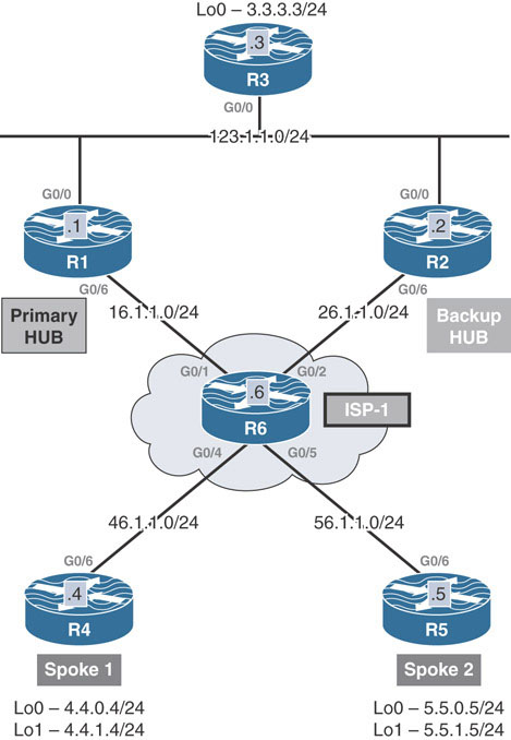
This lab introduces advanced ways a functional DMVPN can be engineered to control how traffic is forwarded in the DMVPN network outside of editing routing protocol metrics. This section introduces concepts of NHS Clustering and DMVPN with DHCP. The first topic will be DMVPN NHS Clustering.
This lab should be conducted on the Enterprise Rack.
Lab Setup:
If you are using EVE-NG, and you have imported the EVE-NG topology from the EVE-NG-Topology folder, ignore the following and use Lab-5-DMVPN NHS Clustering in the DMVPN folder in EVE-NG.
To copy and paste the initial configurations, go to the Initial-config folder → DMVPN folder → Lab-5.
Task 1
Configure DMVPN Phase 3 on R1, R2, R4, and R5:
R1 and R2 should be configured as NHRP NHSs.
R4 and R5 should be configured as spokes.
This task uses a single-cloud, dual-hub Phase 3 DMVPN design, with R1 and R2 serving as the hubs. These hubs are connected to a shared LAN segment with R3, which is also attached to another subnet, 3.3.3.0/24. Remote sites at R4 and R5 should have connectivity to the 3.3.3.0/24 subnet.
To complete the task and configure the hub and spoke routers, the following configurations should be applied on the hubs R1 and R2:
On R1:
R1(config)#interface tunnel 100 R1(config-if)#ip address 100.1.1.1 255.255.255.0 R1(config-if)#tunnel source 16.1.1.1 R1(config-if)#tunnel mode gre multipoint R1(config-if)#ip nhrp network-id 100 R1(config-if)#ip nhrp map multicast 46.1.1.4 R1(config-if)#ip nhrp map multicast 56.1.1.5 R1(config-if)#ip nhrp redirect
On R2:
R2(config)#interface tunnel 100 R2(config-if)#ip address 100.1.1.2 255.255.255.0 R2(config-if)#tunnel source 26.1.1.2 R2(config-if)#tunnel mode gre multipoint R2(config-if)#ip nhrp network-id 100 R2(config-if)#ip nhrp map multicast 46.1.1.4 R2(config-if)#ip nhrp map multicast 56.1.1.5 R2(config-if)#ip nhrp redirect
These configurations lay the ground for DMVPN communication. Next, spokes R4 and R5 are configured to register with the hubs R1 and R2 and dynamically join the DMVPN:
On R4:
R4(config)#interface tunnel 100 R4(config-if)#ip address 100.1.1.4 255.255.255.0 R4(config-if)#tunnel source 46.1.1.4 R4(config-if)#tunnel mode gre multipoint R4(config-if)#ip nhrp network-id 100 R4(config-if)#ip nhrp nhs 100.1.1.1 nbma 16.1.1.1 multicast R4(config-if)#ip nhrp nhs 100.1.1.2 nbma 26.1.1.2 multicast R4(config-if)#ip nhrp shortcut
On R5:
R5(config)#interface tunnel 100 R5(config-if)#ip address 100.1.1.5 255.255.255.0 R5(config-if)#tunnel source 56.1.1.5 R5(config-if)#tunnel mode gre multipoint R5(config-if)#ip nhrp network-id 100 R5(config-if)#ip nhrp nhs 100.1.1.1 nbma 16.1.1.1 multicast R5(config-if)#ip nhrp nhs 100.1.1.2 nbma 26.1.1.2 multicast R5(config-if)#ip nhrp shortcut
To verify the configuration:
On completing the above configurations, outputs below from R1 and R2 confirm the spokes have successfully registered with both hubs:
On R1:
R1#show ip nhrp
100.1.1.4/32 via 100.1.1.4
Tunnel100 created 00:02:57, expire 00:07:02
Type: dynamic, Flags: registered nhop
NBMA address: 46.1.1.4
100.1.1.5/32 via 100.1.1.5
Tunnel100 created 00:00:59, expire 00:09:00
Type: dynamic, Flags: registered nhop
NBMA address: 56.1.1.5
R1#show ip nhrp multicast
I/F NBMA address
Tunnel100 56.1.1.5 Flags: static (Enabled)
Tunnel100 46.1.1.4 Flags: static (Enabled)
On R2:
R2#show dmvpn | begin Peer NBMA
# Ent Peer NBMA Addr Peer Tunnel Add State UpDn Tm Attrb
----- --------------- --------------- ----- -------- -----
1 46.1.1.4 100.1.1.4 UP 00:03:29 D
1 56.1.1.5 100.1.1.5 UP 00:01:40 D
R2#show ip nhrp multicast
I/F NBMA address
Tunnel100 46.1.1.4 Flags: dynamic (Enabled)
Tunnel100 56.1.1.5 Flags: dynamic (Enabled)
Task 2
Configure EIGRP AS 1 based on the following policy:
R1 and R2: G0/0 and tunnel interfaces
R3: G0/0 and Lo0
R4 and R5: Tunnel 100 interfaces and Lo0 and Lo1
As specified in the task, the following configures EIGRP as the overlay routing protocol on R1, R2, R3, R4, and R5. EIGRP is enabled on the tunnel interfaces and the loopback interfaces specified in the task with the network statement:
On R1:
R1(config)#router eigrp 1 R1(config-router)#network 100.1.1.1 0.0.0.0 R1(config-router)#network 123.1.1.1 0.0.0.0
On R2:
R2(config)#router eigrp 1 R2(config-router)#network 100.1.1.2 0.0.0.0 R2(config-router)#network 123.1.1.2 0.0.0.0
You should see the following console message:
%DUAL-5-NBRCHANGE: EIGRP-IPv4 1: Neighbor 123.1.1.1
(GigabitEthernet0/0) is up: new adjacency
On R4:
R4(config)#router eigrp 1 R4(config-router)#network 100.1.1.4 0.0.0.0 R4(config-router)#network 4.4.0.4 0.0.0.0 R4(config-router)#network 4.4.1.4 0.0.0.0
You should see the following console messages:
%DUAL-5-NBRCHANGE: EIGRP-IPv4 1: Neighbor 100.1.1.2 (Tunnel100) is up: new adjacency %DUAL-5-NBRCHANGE: EIGRP-IPv4 1: Neighbor 100.1.1.1 (Tunnel100) is up: new adjacency
On R5:
R5(config)#router eigrp 1 R5(config-router)#network 100.1.1.5 0.0.0.0 R5(config-router)#network 5.5.0.5 0.0.0.0 R5(config-router)#network 5.5.1.5 0.0.0.0
You should see the following console messages:
%DUAL-5-NBRCHANGE: EIGRP-IPv4 1: Neighbor 100.1.1.2 (Tunnel100) is up: new adjacency %DUAL-5-NBRCHANGE: EIGRP-IPv4 1: Neighbor 100.1.1.1 (Tunnel100) is up: new adjacency
On R3:
R3(config)#router eigrp 1 R3(config-router)#network 123.1.1.3 0.0.0.0 R3(config-router)#network 3.3.3.3 0.0.0.0
You should see the following console messages:
%DUAL-5-NBRCHANGE: EIGRP-IPv4 1: Neighbor 123.1.1.2 (GigabitEthernet0/10) is up: new adjacency %DUAL-5-NBRCHANGE: EIGRP-IPv4 1: Neighbor 123.1.1.1 (GigabitEthernet0/10) is up: new adjacency
To verify the configuration:
The show ip route eigrp command output below verifies the EIGRP routes learned over the DMVPN network:
On R4:
R4#show ip route eigrp 1 | begin Gate
Gateway of last resort is not set
3.0.0.0/24 is subnetted, 1 subnets
D 3.3.3.0 [90/27008256] via 100.1.1.2, 00:03:32, Tunnel100
[90/27008256] via 100.1.1.1, 00:03:32, Tunnel100
123.0.0.0/24 is subnetted, 1 subnets
D 123.1.1.0 [90/26880256] via 100.1.1.2, 00:09:59, Tunnel100
[90/26880256] via 100.1.1.1, 00:09:59, Tunnel100
On R5:
R5#show ip route eigrp 1 | begin Gate
Gateway of last resort is not set
3.0.0.0/24 is subnetted, 1 subnets
D 3.3.3.0 [90/27008256] via 100.1.1.2, 00:03:57, Tunnel100
[90/27008256] via 100.1.1.1, 00:03:57, Tunnel100
123.0.0.0/24 is subnetted, 1 subnets
D 123.1.1.0 [90/26880256] via 100.1.1.2, 00:08:31, Tunnel100
[90/26880256] via 100.1.1.1, 00:08:31, Tunnel100
On R1:
R1#show ip route eigrp 1 | begin Gate
Gateway of last resort is not set
3.0.0.0/24 is subnetted, 1 subnets
D 3.3.3.0 [90/130816] via 123.1.1.3, 00:04:44,
GigabitEthernet0/10
4.0.0.0/24 is subnetted, 2 subnets
D 4.4.0.0 [90/27008000] via 100.1.1.4, 00:11:05, Tunnel100
D 4.4.1.0 [90/27008000] via 100.1.1.4, 00:11:01, Tunnel100
5.0.0.0/24 is subnetted, 2 subnets
D 5.5.0.0 [90/27008000] via 100.1.1.5, 00:09:12, Tunnel100
D 5.5.1.0 [90/27008000] via 100.1.1.5, 00:09:08, Tunnel100
On R2:
R2#show ip route eigrp 1 | begin Gate
Gateway of last resort is not set
3.0.0.0/24 is subnetted, 1 subnets
D 3.3.3.0 [90/130816] via 123.1.1.3, 00:05:12,
GigabitEthernet0/10
4.0.0.0/24 is subnetted, 2 subnets
D 4.4.0.0 [90/27008000] via 100.1.1.4, 00:11:33, Tunnel100
D 4.4.1.0 [90/27008000] via 100.1.1.4, 00:11:29, Tunnel100
5.0.0.0/24 is subnetted, 2 subnets
D 5.5.0.0 [90/27008000] via 100.1.1.5, 00:09:41, Tunnel100
D 5.5.1.0 [90/27008000] via 100.1.1.5, 00:09:36, Tunnel100
Notice that R4 and R5 do not contain the specific prefixes for each other’s networks. This is because, by default, split horizon is enabled under the tunnel interfaces. To remedy this issue, use the no ip split-horizon eigrp 1 command in the tunnel 100 interface on R1 and R2:
On R1 and R2:
Rx(config)#interface tunnel 100
Rx(config-if)#no ip split-horizon eigrp 1
With split horizon disabled, R4 and R5 now learn the remaining specific routes from the hubs.
To verify the configuration:
On R4:
R4#show ip route eigrp 1 | begin Gate
Gateway of last resort is not set
3.0.0.0/24 is subnetted, 1 subnets
D 3.3.3.0 [90/27008256] via 100.1.1.2, 00:05:01, Tunnel100
[90/27008256] via 100.1.1.1, 00:05:01, Tunnel100
5.0.0.0/24 is subnetted, 2 subnets
D 5.5.0.0 [90/28288000] via 100.1.1.2, 00:01:10, Tunnel100
[90/28288000] via 100.1.1.1, 00:01:10, Tunnel100
D 5.5.1.0 [90/28288000] via 100.1.1.2, 00:01:10, Tunnel100
[90/28288000] via 100.1.1.1, 00:01:10, Tunnel100
123.0.0.0/24 is subnetted, 1 subnets
D 123.1.1.0 [90/26880256] via 100.1.1.2, 00:05:01, Tunnel100
[90/26880256] via 100.1.1.1, 00:05:01, Tunnel100
On R5:
R5#show ip route eigrp 1 | begin Gate
Gateway of last resort is not set
3.0.0.0/24 is subnetted, 1 subnets
D 3.3.3.0 [90/27008256] via 100.1.1.2, 00:04:20, Tunnel100
[90/27008256] via 100.1.1.1, 00:04:20, Tunnel100
4.0.0.0/24 is subnetted, 2 subnets
D 4.4.0.0 [90/28288000] via 100.1.1.2, 00:01:43, Tunnel100
[90/28288000] via 100.1.1.1, 00:01:43, Tunnel100
D 4.4.1.0 [90/28288000] via 100.1.1.2, 00:01:43, Tunnel100
[90/28288000] via 100.1.1.1, 00:01:43, Tunnel100
123.0.0.0/24 is subnetted, 1 subnets
D 123.1.1.0 [90/26880256] via 100.1.1.2, 00:04:20, Tunnel100
[90/26880256] via 100.1.1.1, 00:04:20, Tunnel100
Task 3
Configure R1 to be the primary hub and R2 to be the backup. You must use NHRP clustering to accomplish this task.
This task involves traffic engineering using clustering instead of manipulating routing protocol metrics. The routing table on R4 has two equal-cost paths to reach all the networks over the DMVPN tunnel:
R4#show ip route eigrp 1 | begin Gate
Gateway of last resort is not set
3.0.0.0/24 is subnetted, 1 subnets
D 3.3.3.0 [90/27008256] via 100.1.1.2, 00:17:46, Tunnel100
[90/27008256] via 100.1.1.1, 00:17:46, Tunnel100
5.0.0.0/24 is subnetted, 2 subnets
D 5.5.0.0 [90/28288000] via 100.1.1.2, 00:00:06, Tunnel100
[90/28288000] via 100.1.1.1, 00:00:06, Tunnel100
D 5.5.1.0 [90/28288000] via 100.1.1.2, 00:00:06, Tunnel100
[90/28288000] via 100.1.1.1, 00:00:06, Tunnel100
123.0.0.0/24 is subnetted, 1 subnets
D 123.1.1.0 [90/26880256] via 100.1.1.2, 00:17:46, Tunnel100
[90/26880256] via 100.1.1.1, 00:17:46, Tunnel100
R1 and R2 are advertising equal-cost paths to R4 across the DMVPN network. According to the task, R4 should prefer to use R1’s route over R2’s unless it loses the route to R1 due to a failure. In the current configuration, R4 will load share traffic between the two destinations. Typically, as in the earlier tasks of this lab, this problem was solved by engineering routing protocol metrics. This task, however, requires the use of NHRP NHS clustering, a feature introduced in IOS 15.1.2T.
With NHRP NHS clustering, NHSs serving the same DMVPN cloud are placed into groups designated by a cluster ID. Under normal operating circumstances, spokes register with all hubs in the cluster. Failover redundancy is implemented by limiting the number of NHSs in a given cluster to which the spokes can build connections to only connect with a subset of all NHSs at a time. Within each NHS cluster, the member NHSs are given priority values between 1 and 255. Priority value 1 is the highest preference, and value 255 is the lowest preference. The spoke will attempt a connection with the highest-priority NHSs within each cluster up to the defined maximum connection limit. These will be the NHSs with the numerically lowest priority values.
This configuration is all accomplished on the spoke interfaces. Therefore, the NHRP NHS clustering configuration is only locally significant to the spoke on which it is configured. Different spokes can group available NHSs to different clusters and priority values, depending on the desired policies.
An NHS is assigned to a cluster using the interface configuration command ip nhrp nhs ip-address-of-nhs priority priority-value cluster cluster-id on the spoke tunnel interface. To limit the number of NHSs to which a spoke will open connections, use the ip nhrp nhs cluster cluster-id max-connections number-of-connections command. The following configures this feature on spokes R4 and R5:
On R4 and R5:
Rx(config)#interface tunnel 100 Rx(config-if)#ip nhrp nhs 100.1.1.1 priority 1 cluster 1 Rx(config-if)#ip nhrp nhs 100.1.1.2 priority 2 cluster 1
After entering the above on the spokes, the original ip nhrp nhs x.x.x.x nbma x.x.x.x multicast command is replaced with the above command. Only one version of this command can be entered in the tunnel interface. This results in the mapping statements from the tunnel interfaces being automatically removed by IOS. You need to reconfigure mapping statements on the spokes with the legacy NHRP mapping statements.
The following reconfigures the static NHRP mapping for hubs R1 and R2 along with multicast mappings on both spokes:
Rx(config-if)#ip nhrp map multicast 16.1.1.1 Rx(config-if)#ip nhrp map multicast 26.1.1.2 Rx(config-if)#ip nhrp map 100.1.1.1 16.1.1.1 Rx(config-if)#ip nhrp map 100.1.1.2 26.1.1.2
The following configuration limits the spokes to only connect with a single NHS in cluster 1 and configures a registration timeout limit:
Rx(config-if)#ip nhrp nhs cluster 1 max-connections 1 Rx(config-if)#ip nhrp registration timeout 5
After making the above configuration changes, R4 and R5 are configured with NHRP NHS cluster 1. They are also configured to only create a connection with a single NHS from cluster 1 due to the ip nhrp nhs cluster x max-connections 1 command. As a result, R4 and R5 will attempt to register with the highest-priority cluster in NHS cluster 1 first. If there is no response after 5 seconds (the configured timeout value), it will move to the next-lowest-priority NHS. In this case, R4 and R5 will attempt a connection with R1 first. If the connection is completed, the routers will not connect with R2. This prevents R2 from advertising a second set of routes to the spokes and makes R1 the preferred next hop for all DMVPN traffic, as shown below:
On R4:
R4#show ip route eigrp 1 | begin Gate
Gateway of last resort is not set
3.0.0.0/24 is subnetted, 1 subnets
D 3.3.3.0 [90/27008256] via 100.1.1.1, 00:18:52, Tunnel100
5.0.0.0/24 is subnetted, 2 subnets
D 5.5.0.0 [90/28288000] via 100.1.1.1, 00:18:52, Tunnel100
D 5.5.1.0 [90/28288000] via 100.1.1.1, 00:18:52, Tunnel100
123.0.0.0/24 is subnetted, 1 subnets
D 123.1.1.0 [90/26880256] via 100.1.1.1, 00:18:52, Tunnel100
On R5:
R5#show ip route eigrp 1 | begin Gate
Gateway of last resort is not set
3.0.0.0/24 is subnetted, 1 subnets
D 3.3.3.0 [90/27008256] via 100.1.1.1, 00:19:08, Tunnel100
4.0.0.0/24 is subnetted, 2 subnets
D 4.4.0.0 [90/28288000] via 100.1.1.1, 00:19:52, Tunnel100
D 4.4.1.0 [90/28288000] via 100.1.1.1, 00:19:52, Tunnel100
123.0.0.0/24 is subnetted, 1 subnets
D 123.1.1.0 [90/26880256] via 100.1.1.1, 00:19:08, Tunnel100
The advantage of this setup is that, if R1 fails, the spokes will automatically bring up the connection with the backup hub, R2, and reestablish IGP connectivity. To demonstrate, a ping is issued from R4’s Lo0 interface to the Lo0 interface on R3 with a high repeat count. While the ping is executed, the G0/1 interface on R6 is shut down:
On R4:
R4#ping 3.3.3.3 source lo0 repeat 100000 Type escape sequence to abort. Sending 100000, 100-byte ICMP Echos to 3.3.3.3, timeout is 2 seconds: Packet sent with a source address of 4.4.0.4 !!!!!!!!!!!!!!!!!!!!!!!!!!!!!!!!!!!!!!!!!!!!!!!!!!!!!!!!!!!!!!!!!!!!!! !!!!!!!!!!!!!!!!!!!!!!!!!!!!!!!!!!!!!!!!!!!!!!!!!!!!!!!!!!!!!!!!!!!!!!
On R6:
R6(config)#interface g0/1 R6(config-if)#shut
On R4:
!!!!!!!!!!!!!!!!!!!!!!!!!!!!!!!!!!!!!!!!!!!!!!!!!!!!!!!!!!!!!!!!!!!!!!
!!!!!!!!!!!!!!!!!!!!!!!!!!!!!!!!!!!!!!!!!!!!!!!!!!!!!!!!!!!!!!!!!!!!!!
!!!!!!!!!!!!!!!!!!!!!!!!!!!!!!!!!!!!!!!!!!!!!!!!!!!!!!!.......!!!!!!!!
!!!!!!!!!!!!!!!!!!!!!!!!!!!!!!!!!!!!!!!!!!!!!!!!!!!!!!!!!!!!!!!!!!!!!!
!!!!!!!!!!!!!!!!!!!!!!!!!!!!!!!!!!!!!!!!!!!!!!!!!!!!!!!!!!!!!!
In the above, the highlighted missed pings indicate the time it took for R4 to switch over to using R2 as its hub. With the ping timeout of 2 seconds, this equates to about 14 seconds of downtime. The show ip route eigrp 1 | begin Gate and traceroute output verifies that R4 has switched to using R2 as its next hop for the EIGRP routes:
To verify the configuration:
On R4:
R4#show ip route eigrp 1 | begin Gate
Gateway of last resort is not set
3.0.0.0/24 is subnetted, 1 subnets
D 3.3.3.0 [90/27008256] via 100.1.1.2, 00:06:48, Tunnel100
5.0.0.0/24 is subnetted, 2 subnets
D 5.5.0.0 [90/28288000] via 100.1.1.2, 00:06:46, Tunnel100
D 5.5.1.0 [90/28288000] via 100.1.1.2, 00:06:46, Tunnel100
123.0.0.0/24 is subnetted, 1 subnets
D 123.1.1.0 [90/26880256] via 100.1.1.2, 00:06:48, Tunnel100
R4#traceroute 3.3.3.3 source lo0 probe 1
Type escape sequence to abort.
Tracing the route to 3.3.3.3
VRF info: (vrf in name/id, vrf out name/id)
1 100.1.1.2 65 msec
2 123.1.1.3 10 msec
The ip nhrp nhs fallback command controls how long the router will take to switch back over to the original NHS whenever it is recovered. To test this, the ip nhrp nhs fallback 5 command is issued on R4 and R5. This means the routers will wait 5 seconds before using R1 as the higher-priority NHS when connectivity to R1 is restored. The same ping test is repeated, this time with the G0/1 interface on R6 being no shut to simulate the connection being restored:
On R4 and R5:
Rx(config)#interface tunnel 100 Rx(config-if)#ip nhrp nhs fallback 5
This configuration is tested by repeating the same ping and bringing R6’s G0/1 interface back up:
On R4:
R4#ping 3.3.3.3 source lo0 rep 100000 Type escape sequence to abort. Sending 100000, 100-byte ICMP Echos to 3.3.3.3, timeout is 2 seconds: Packet sent with a source address of 4.4.0.4 !!!!!!!!!!!!!!!!!!!!!!!!!!!!!!!!!!!!!!!!!!!!!!!!!!!!!!!!!!!!!!!!!!!!!! !!!!!!!!!!!!!!!!!!!!!!!!!!!!!!!!!!!!!!!!!!!!!!!!!!!!!!!!!!!!!!!!!!!!!! !!!!!!!!!!!!!!!!!!!!!!!!!!!!!!!!!!!!!!!!!!!!!!!!!!!!!!!!!!!!!!!!!!!!!!
On R6:
R6(config)#interface g0/1
R6(config-if)#no shut
Notice in the above that no pings were missed. The show ip route eigrp 1 | begin Gate and accompanying traceroute command on R4 verify that R1 has indeed come back up.
On R4:
R4#show ip route eigrp 1 | begin Gate
Gateway of last resort is not set
3.0.0.0/24 is subnetted, 1 subnets
D 3.3.3.0 [90/27008256] via 100.1.1.1, 00:00:04, Tunnel100
5.0.0.0/24 is subnetted, 2 subnets
D 5.5.0.0 [90/28288000] via 100.1.1.1, 00:00:07, Tunnel100
D 5.5.1.0 [90/28288000] via 100.1.1.1, 00:00:07, Tunnel100
123.0.0.0/24 is subnetted, 1 subnets
D 123.1.1.0 [90/26880256] via 100.1.1.1, 00:00:04, Tunnel100
R4#traceroute 3.3.3.3 source lo0 probe 1
Type escape sequence to abort.
Tracing the route to 3.3.3.3
VRF info: (vrf in name/id, vrf out name/id)
1 100.1.1.1 5 msec
2 123.1.1.3 7 msec
The pings weren’t missed because there was no connection failure during fallback; it was a connection restoration. Because R2 is up during the entire process, R4 can continue to forward traffic through R2 while the EIGRP neighbor relationship comes up between itself and R1. R1 comes up and establishes an adjacency with R4. R4 adds the new routing information for the prefixes transparently during fallback.
The key to making all of this work is the ip nhrp nhs cluster 1 max-connections 1 command issued on the spoke tunnel interfaces. This is what limits the connection to only a single NHS at a time. Without this command, the spokes would connect to both NHSs at the same time, and the traffic engineering goals would not be met.
The show ip nhrp nhs redundancy command can be issued on the spokes to reveal the status of every NHS configured. Following is example output from R4:
R4#show ip nhrp nhs redundancy Legend: E=Expecting replies, R=Responding, W=Waiting No. Interface Cluster NHS Priority Cur-State Cur-Queue Prev-State Prev-Queue 1 Tunnel100 1 100.1.1.1 1 RE Running E Running 2 Tunnel100 1 100.1.1.2 2 W Waiting RE Running No. Interface Cluster Status Max-Con Total-NHS Registering/UP Expecting Waiting Fallback 1 Tunnel100 1 Enable 1 2 1 0 1 0
The output above shows that R4 has a connection to 100.1.1.1 (R1) over its tunnel 100 interface. This NHS is in cluster 1 with priority 1. The Curr-State field contains the RE flag, meaning the NHS is responding to probes, and the local spoke is expecting replies. The Cur-Queue status is Running because it is the active NHS. It also lists similar information for NHS 100.1.1.2 (R2); however, in this case, the priority is 2, and the state is W, which means it is waiting for connections.
The bottom part of the output provides details on the configured clusters. Notice that the Max-Con field is set to 1 for cluster 1. This is verification that only one NHS from that cluster will be used for communication.
Task 4
Erase the startup configuration of the routers and reload them before proceeding to the next lab.
Lab 6: DMVPN and DHCP
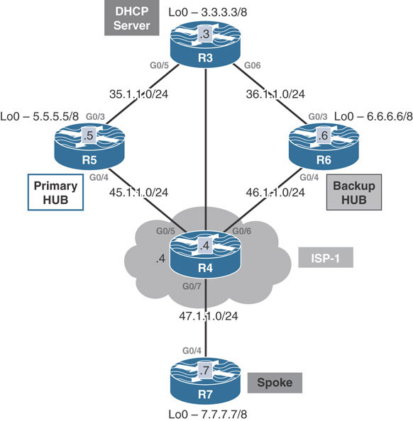
This lab should be conducted on the Enterprise Rack.
Lab Setup:
If you are using EVE-NG, and you have imported the EVE-NG topology from the EVE-NG-Topology folder, ignore the following and use Lab-6-DMVPN and DHCP in the DMVPN folder in EVE-NG.
To copy and paste the initial configurations, go to the Initial-config folder → DMVPN folder → Lab-6.
This lab introduces concepts that can be used for situations in which the spokes of the DMVPN network do not have statically assigned tunnel IP addresses. In this case, the spokes are configured to receive their IP addressing information from a DHCP server located at a central main site location. The hub is then configured to act as a DHCP relay agent to pass the DHCP DISCOVER packets from the spokes to the DHCP server. The DMVPN network shown below will be configured to demonstrate this functionality:
Task 1
Configure DMVPN Phase 3 such that R5 is the primary hub, R6 is the backup hub, and R7 is configured as the spoke. You should use EIGRP AS 1 to provide reachability to the NBMA IP addresses and EIGRP AS 100 for the tunnel and the loopback interfaces.
In this task, Phase 3 DMVPN is configured between R5, R6, and R7. R5 and R6 are the hubs, R7 is the spoke, and R4 represents the cloud. This task requires R5 to be the primary hub and R6 to be the backup hub. However, prior to any DMVPN-related configuration, IP reachability needs to be established for underlying NBMA addresses on R5, R6, and R7. This reachability is advertised over the underlay using EIGRP AS 1, as shown below:
On R5:
R5(config)#router eigrp 1 R5(config-router)#network 45.1.1.5 0.0.0.0
On R6:
R6(config)#router eigrp 1 R6(config-router)#network 46.1.1.6 0.0.0.0
On R7:
R7(config)#router eigrp 1 R7(config-router)#network 47.1.1.7 0.0.0.0
On R4:
R4(config)#router eigrp 1 R4(config-router)#network 0.0.0.0 0.0.0.0
You should see the following console messages:
%DUAL-5-NBRCHANGE: EIGRP-IPv4 1: Neighbor 45.1.1.5 (GigabitEthernet0/5) is up: new adjacency %DUAL-5-NBRCHANGE: EIGRP-IPv4 1: Neighbor 46.1.1.6 (GigabitEthernet0/6) is up: new adjacency %DUAL-5-NBRCHANGE: EIGRP-IPv4 1: Neighbor 47.1.1.7 (GigabitEthernet0/7) is up: new adjacency
The next step is to complete the DMVPN Phase 3 configuration on the hubs R5 and R6. The following configuration commands set up these routers as hubs for DMVPN Phase 3:
On R5:
R5(config)#interface tunnel 100 R5(config-if)#ip address 100.1.1.5 255.255.255.0 R5(config-if)#tunnel source g0/4 R5(config-if)#tunnel mode gre multipoint R5(config-if)#ip nhrp network 100 R5(config-if)#ip nhrp map multicast dynamic R5(config-if)#ip nhrp redirect
On R6:
R6(config)#interface tunnel 100 R6(config-if)#ip address 100.1.1.6 255.255.255.0 R6(config-if)#tunnel source g0/4 R6(config-if)#tunnel mode gre multipoint R6(config-if)#ip nhrp network 111 R6(config-if)#ip nhrp map multicast dynamic R6(config-if)#ip nhrp redirect
The hub configuration is pretty straightforward. One peculiarity is the ip nhrp network-id setting used on the two hubs. R5 uses the ID 100, while R6 uses the ID 111. The NHRP IDs are locally significant to the routers and have no effect on the function of the DMVPN network. The network ID is used by the local router to distinguish between multiple NHRP databases when configured with multiple tunnels.
The configuration on R7, the spoke, deserves some explanation. To implement the requirement that R5 should be the primary hub and R6 should be the secondary hub, R7 is configured with NHRP clustering. R5 and R6 are both configured as potential DMVPN NHS hubs in R7’s configuration. The two hubs are given separate priority values in the same cluster, with R5 being preferred over R6. Then R7 is limited to only a single NHS connection for the same cluster, using the ip nhrp nhs cluster 1 max-connections 1 command:
On R7:
R7(config)#interface tunnel 100 R7(config-if)#ip address 100.1.1.7 255.255.255.0 R7(config-if)#tunnel source g0/4 R7(config-if)#tunnel mode gre multipoint R7(config-if)#ip nhrp network 100 R7(config-if)#ip nhrp map multicast 45.1.1.5 R7(config-if)#ip nhrp map multicast 46.1.1.6 R7(config-if)#ip nhrp map 100.1.1.5 45.1.1.5 R7(config-if)#ip nhrp map 100.1.1.6 46.1.1.6 R7(config-if)#ip nhrp nhs 100.1.1.5 priority 1 cluster 1 R7(config-if)#ip nhrp nhs 100.1.1.6 priority 2 cluster 1 R7(config-if)#ip nhrp shortcut R7(config-if)#ip nhrp nhs cluster 1 max-connections 1
To verify the configuration:
On R5:
R5#show ip nhrp 100.1.1.7/32 via 100.1.1.7 Tunnel100 created 00:01:56, expire 00:09:58 Type: dynamic, Flags: registered nhop NBMA address: 47.1.1.7 R5#show ip nhrp multicast I/F NBMA address Tunnel100 47.1.1.7 Flags: dynamic (Enabled)
On R6:
Since R6 is the backup NHS, the spoke R7 will not send a NHRP registration to it unless the primary hub R5 fails. As a result, the show ip nhrp output on R6 does not produce any output:
R6#show ip nhrp R6#
On R7:
R7#show ip nhrp
100.1.1.5/32 via 100.1.1.5
Tunnel100 created 00:03:04, never expire
Type: static, Flags:
NBMA address: 45.1.1.5
100.1.1.6/32 via 100.1.1.6
Tunnel100 created 00:02:53, never expire
Type: static, Flags:
NBMA address: 46.1.1.6
(no-socket)
Here, R6 does not have an entry for R7’s mapping information because R7 is only configured to send a registration request to the highest-priority hub in NHRP cluster 1, R5. As such, R7’s show ip nhrp output lists R6 as a static mapping but with the no-socket status because R7 is using it as a backup and hasn’t yet initiated a session directly with R6.
Next, in keeping with the task requirements, EIGRP 100 is used as the overlay routing protocol to advertise the Loopback0 interfaces across the DMVPN network. This should be configured on R3, R5, R6, and R7:
On R3:
R3(config)#router eigrp 100 R3(config-router)#network 3.3.3.3 0.0.0.0 R3(config-router)#network 35.1.1.3 0.0.0.0 R3(config-router)#network 36.1.1.3 0.0.0.0
On R5:
R1(config)#router eigrp 100 R5(config-router)#network 5.5.5.5 0.0.0.0 R5(config-router)#network 100.1.1.5 0.0.0.0 R5(config-router)#network 35.1.1.5 0.0.0.0
You should see the following console message:
%DUAL-5-NBRCHANGE: EIGRP-IPv4 100: Neighbor 35.1.1.3
(GigabitEthernet0/3) is up: new adjacency
On R6:
R6(config)#router eigrp 100 R6(config-router)#network 6.6.6.6 0.0.0.0 R6(config-router)#network 36.1.1.6 0.0.0.0 R6(config-router)#network 100.1.1.6 0.0.0.0
You should see the following console message:
%DUAL-5-NBRCHANGE: EIGRP-IPv4 100: Neighbor 36.1.1.3 (GigabitEthernet0/3)is up: new adjacency
On R7:
R7(config)#router eigrp 100 R7(config-router)#network 7.7.7.7 0.0.0.0 R7(config-router)#network 100.1.1.7 0.0.0.0
You should see the following console message:
%DUAL-5-NBRCHANGE: EIGRP-IPv4 100: Neighbor 100.1.1.5 (Tunnel100) is
up: new adjacency
To verify the configuration:
R7#show ip route eigrp 100 | begin Gate
Gateway of last resort is not set
D 3.0.0.0/8 [90/27008256] via 100.1.1.5, 00:00:53, Tunnel100
D 5.0.0.0/8 [90/27008000] via 100.1.1.5, 00:00:53, Tunnel100
D 6.0.0.0/8 [90/27008512] via 100.1.1.5, 00:00:53, Tunnel100
35.0.0.0/24 is subnetted, 1 subnets
D 35.1.1.0 [90/26880256] via 100.1.1.5, 00:00:53, Tunnel100
36.0.0.0/24 is subnetted, 1 subnets
D 36.1.1.0 [90/26880512] via 100.1.1.5, 00:00:53, Tunnel100
Task 2
Configure R3 as a DHCP server. R7 should be reconfigured as a DHCP client. In the event that R5 is down, R7 should go through R6 to acquire an IP address.
Typically, in DMVPN setups, both the spokes and the hubs are configured with specific static IP addresses. Manually configuring the IP address for each DMVPN spoke is difficult because the spoke configurations will vary based on the IP address configuration. In order to make the spoke configurations easier and require less interaction, the spokes can obtain their IP addresses automatically, through DHCP. This task is designed to demonstrate how a spoke can be configured to obtain an IP address from a DHCP server before participating in a DMVPN using the DHCP tunnel feature.
Pulling off this configuration requires modifications to the typical DMVPN registration process. In a normal DMVPN network, where the spokes are configured with static IP addresses, when the GRE tunnel interface comes up, the spoke immediately begins sending NHRP registration messages to the hub. The hub builds a dynamic NHRP mapping for the spoke that registered with it, and the tunnel between the hub and spoke comes up. When the spoke is configured to obtain an IP address through DHCP, the spoke needs to obtain an IP address before bringing its tunnel interface up and beginning the NHRP registration process.
If this discussion were about normal DHCP operation, the spoke would broadcast a DHCPDISCOVER message onto the LAN. This broadcast would be picked up by a DHCP server, which would send a DHCPOFFER message. The spoke would confirm that it accepted the offer by sending a DHCPREQUEST packet back to the DHCP server. The DHCP server would then reply with a DHCPACK packet. This process is known as the DHCP DORA (discover, offer, request, acknowledge) process.
The problem with this process when applied to a DMVPN network is that DMVPN networks are NBMA networks, which means broadcasts cannot be forwarded across them. When a spoke needs to send its DHCPDISCOVER packet out, the spoke cannot send it as a native broadcast. Instead, the spoke must convert the DHCPDISCOVER packet into a unicast packet that can be tunneled over the underlay network. In addition to having to forward as unicast over the DMVPN network to obtain an IP address, the spoke needs to know the NBMA address of the device to which it should send the unicasted broadcast DHCP packet in order to successfully tunnel it over the underlay network.
The only device spoke router that is typically preloaded with NBMA mapping information is the hub router. A basic spoke configuration includes the tunnel-to-NBMA IP address mapping information. This indicates the default location to which the spoke will send its DHCPDISCOVER packet.
When the spoke tunnel interface is enabled, it first realizes it is supposed to receive an IP address through DHCP. Having no IP address, the spoke cannot send NHRP register packets to the hub, so it suppresses the NHRP registration process. During this suppression time, it sends its DHCPDISCOVER packet to the NBMA address of the hub router. It is now up to the hub to take action.
At this point in the process, the spoke has sent a DHCPDISCOVER packet to the hub, in the hopes that the hub can do one of two things:
Provide the spoke with IP address configuration information
Forward the DHCPDISCOVER packet to another device that can provide IP address configuration information
To perform the first function, the DMVPN hub itself needs to be functioning as a DHCP server. Depending on the IOS version in use, the hub may not be able to be both the DMVPN hub and the DHCP server; some documentation explicitly states that such a configuration is not possible, while other documentation allows this type of configuration.
To perform the second function, the DMVPN hub acts as a DHCP relay agent. A DHCP relay agent is a device that is preconfigured with the unicast IP address of a functioning DHCP server that exists somewhere on the network. The DHCP relay agent has full unicast reachability to these devices and acts as a proxy between DHCP clients and DHCP servers. The job of the DHCP relay agent is to connect DHCP clients with DHCP servers that are in other subnets. The DHCP relay agent does so by converting the broadcast DHCPDISCOVER packet into a unicast DHCPDISCOVER packet sent directly to one of its preconfigured DCHP servers.
The hub’s actions after receiving the DHCPDISCOVER from a spoke depend on how it’s configured. If the hub is a DHCP server, then it will process the DHCPDISCOVER packet by taking an IP address from its configured pool of addresses. It will create a temporary NBMA-to-tunnel IP address mapping for the spoke and forward the DHCPOFFER packet to the client. The client, if it accepts the IP address, responds with a DHCPREQUEST formally requesting the IP address in the offer. The hub responds with a DHCPACK.
If the hub is configured as a DHCP relay agent, it needs another way of keeping track of the exchange between the spoke and the DHCP server. If multiple spokes are sending DHCPDISCOVER packets at the same time, the hub needs to be sure to return the right DHCPOFFER packets to the right spokes. To do this, on newer IOS versions, the hub adds the NBMA address of the spoke that sent the DHCPDISCOVER to the relay information option 82 field of the DHCP packet it sends to the DHCP server. This way, the information persists when the DHCP server sends a DHCPOFFER packet in response to the DHCPDISCOVER. The hub can send the DHCPOFFER to the spoke by reading the encoded NBMA address of the spoke in the option 82 relay information field. The DHCP DORA process completes, and the spoke obtains its IP addressing information.
After receiving its IP addressing information, the spoke can finally officially bring up its GRE tunnel interface. Once this occurs, the spoke stops suppressing the NHRP registration process and registers its newly acquired tunnel IP address with the hub, as normal.
You have just seen a basic outline of how a spoke obtains an IP address for its DMVPN tunnel interface through DHCP. Because some IOS versions do not support DHCP servers on the hub, this lab uses a model in which the hub is a DHCP relay agent. The DHCP server is located on another subnet that is reachable for the DMVPN hub. The configuration to enable the DHCP tunnel feature involves three steps:
Configure the hub to send unicast DHCP messages.
Configure the hub as a relay agent with the ip helper-address command.
Configure the spokes to clear the broadcast flag in DHCPDISCOVER messages.
The DHCP tunnel feature does not work with broadcast communication. Because of this, any hub that is to act as a relay agent must be configured to send unicast DHCP replies to the appropriate spoke. This is accomplished with the ip dhcp support tunnel unicast command in global configuration mode.
Second, after the hub has been configured to send unicast DHCP replies, it is configured with the ip helper-address command to enable its relay agent features.
Finally, the spoke itself may interfere with the DHCP reply process. By default, DHCP clients set a flag in the DHCPOFFER packet that forces DHCP communication to use broadcast instead of unicast. This needs to be disabled on the spoke routers with the ip dhcp client broadcast-flag clear command in interface configuration mode for the DMVPN tunnel interface.
These steps will be demonstrated below. R3, the DHCP server, is configured first with a DHCP pool using the ip dhcp pool command. The network command is used to specify the subnet network number and mask of the address pool. ip dhcp excluded-address ensures that the hub’s IP address is not allocated to any spokes:
To configure the DHCP server:
On R3:
R3(config)#ip dhcp pool TST R3(dhcp-config)#network 100.1.1.0 255.255.255.0
Exclude the IP addresses assigned to the hub’s tunnel interfaces:
R3(config)#ip dhcp excluded-address 100.1.1.1 100.1.1.6
The DHCP configuration can be verified using the show ip dhcp pool TST command:
R3#show ip dhcp pool TST Pool TST : Utilization mark (high/low) : 100 / 0 Subnet size (first/next) : 0 / 0 Total addresses : 254 Leased addresses : 0 Pending event : none 1 subnet is currently in the pool : Current index IP address range Leased addresses 100.1.1.1 100.1.1.1 - 100.1.1.254 0
Before leaving R3, another thing needs to be sorted. With the current configuration, there are two paths R3 can use to reach the 100.1.1.0/24 network—through R5 or through R6—as shown below:
R3#show ip route eigrp 100 | begin Gate
Gateway of last resort is not set
D 5.0.0.0/8 [90/130816] via 35.1.1.5, 02:21:46, GigabitEthernet0/5
D 6.0.0.0/8 [90/130816] via 36.1.1.6, 02:21:28, GigabitEthernet0/6
D 7.0.0.0/8 [90/27008256] via 35.1.1.5, 02:18:08,
GigabitEthernet0/5
100.0.0.0/24 is subnetted, 1 subnets
D 100.1.1.0 [90/26880256] via 36.1.1.6, 02:21:25,
GigabitEthernet0/6
[90/26880256] via 35.1.1.5, 02:21:25,
GigabitEthernet0/5
With two paths, R3 may decide to send DHCP reply packets through the backup hub instead of through R5, breaking the DHCP exchange. To remedy this, EIGRP delay is modified on the path via R6 to be artificially higher than the path via R5:
Before:
R3#show interface g0/6 | include DLY
MTU 1500 bytes, BW 1000000 Kbit/sec, DLY 10 usec,
R3(config)#interface g0/6
R3(config-if)#delay 100
After:
R3#show interface g0/6 | include DLY MTU 1500 bytes, BW 1000000 Kbit/sec, DLY 1000 usec, R3#show ip route eigrp 100 | begin Gate Gateway of last resort is not set D 5.0.0.0/8 [90/130816] via 35.1.1.5, 00:01:07, GigabitEthernet0/5 D 6.0.0.0/8 [90/156160] via 36.1.1.6, 00:00:44, GigabitEthernet0/6 D 7.0.0.0/8 [90/27008256] via 35.1.1.5, 00:01:07, GigabitEthernet0/5 100.0.0.0/24 is subnetted, 1 subnets D 100.1.1.0 [90/26880256] via 35.1.1.5, 00:00:44, GigabitEthernet0/5
The result of the EIGRP delay modification can be seen in the show ip route eigrp 100 output above, where only a single path now exists for the 100.1.1.0/24 network. As long as the primary hub is up and running, DHCP reply packets will now be routed to R5 only.
Now that R3 is configured, the two hubs R5 and R6 are configured to allow DHCP. First, the ip dhcp support tunnel unicast command is used to enable unicast DHCP messaging for the tunnel interfaces. Then the relay agent is configured for the tunnel 100 DMVPN tunnel interface with the ip helper-address 3.3.3.3 command (where 3.3.3.3 is the address of the DHCP server at R3):
On R5:
R5(config)#ip dhcp support tunnel unicast
The following command configures R5 to function as a relay agent:
R5(config)#interface tunnel 100 R5(config-if)#ip helper-address 3.3.3.3
On R6:
R6(config)#ip dhcp support tunnel unicast R6(config)#interface tunnel 100 R6(config-if)#ip helper-address 3.3.3.3
The final step is configuration of the DHCP client R7. To begin, tunnel 100 is shut down on R7. Next, some housekeeping is performed. The original EIGRP network statement for the overlay referenced R7’s specific IP address 100.1.1.7/32. Once configured for DHCP, R7 will not know what address its tunnel interface will receive. So, in order to make sure EIGRP is enabled on the tunnel interface, R7’s network command for EIGRP AS 100 needs to be changed to match the entire 100.1.1.0/24 subnet.
The tunnel is first shut down for stability:
On R7:
R7(config)#interface tunnel 100 R7(config-if)#shut
The network eigrp command is modified to include the entire 100.1.1.0/8 subnet:
R7(config)#router eigrp 100
R7(config-router)#no network 100.1.1.7 0.0.0.0
R7(config-router)#network 100.1.1.0 0.0.0.255
The last step is to use the ip dhcp client broadcast-flag clear command to configure R7 to clear the broadcast flag in the DHCPOFFER message and then use the ip address dhcp command to acquire an IP address through DHCP:
R7(config)#interface tun100 R7(config-if)#ip dhcp client broadcast-flag clear R7(config-if)#ip address dhcp
Now, R7’s tunnel 100 interface is brought back up. Notice the log message below, which indicates that it has been assigned the IP address 100.1.1.100 by the DHCP server:
R7(config)#interface tunnel 100
R7(config-if)#no shut
You should see the following console messages:
%LINEPROTO-5-UPDOWN: Line protocol on Interface Tunnel100, changed state to up %LINK-3-UPDOWN: Interface Tunnel100, changed state to up %DUAL-5-NBRCHANGE: EIGRP-IPv4 100: Neighbor 100.1.1.5 (Tunnel100) is up: new adjacency %DHCP-6-ADDRESS_ASSIGN: Interface Tunnel100 assigned DHCP address 100.1.1.100, mask 255.255.255.0, hostname R7
Task 3
Erase the startup configuration of the routers and reload them before proceeding to the next lab.