Chapter 5
Cabling Solutions and Issues
This chapter covers the following official Network+ objectives:
 Summarize the types of cables and connectors and explain which is the appropriate type for a solution.
- Given a scenario, troubleshoot common cable connectivity issues and select the appropriate tools.
This chapter covers CompTIA Network+ objectives 1.3 and 5.2. For more information on the official Network+ exam topics, see the “About the Network+ Exam” section in the Introduction.
When working with an existing network or implementing a new one, you need to identify the characteristics of network media and their associated cabling. This chapter focuses on the media and connectors used in today’s networks and how they fit into wiring closets and beyond.
General Media Considerations
 Summarize the types of cables and connectors and explain which is the appropriate type for a solution.
In addition to identifying the characteristics of network media and their associated cabling, the Network+ exam requires knowledge of some general terms and concepts that are associated with network media. Before you look at the individual media types, it is a good idea to first have an understanding of some general media considerations.
ExamAlert
Remember that this objective begins with “Summarize the types of cables and connectors.” This means that you will need to be able to explain which is the appropriate cable or connector type for a solution.
Broadband Versus Baseband Transmissions
Networks employ two types of signaling methods/modulation techniques:
- Baseband transmissions: Baseband transmissions use digital signaling over a single wire. Communication on baseband transmissions is bidirectional, enabling signals to be sent and received, but not at the same time. To send multiple signals on a single cable, baseband uses something called time-division multiplexing (TDM). TDM divides a single channel into time slots. The key thing about TDM is that it does not change how baseband transmission works—only how data is placed on the cable.
ExamAlert
Most networks use baseband transmissions. (Notice the word base.) Examples are 1000BASE-T and 10GBASE-T.
- Broadband transmissions: In terms of LAN network standards, broadband transmissions use analog transmissions. For broadband transmissions to be sent and received, the medium must be split into two channels. (Alternatively, two cables can be used: one to send and one to receive transmissions.) Multiple channels are created using frequency-division multiplexing (FDM). FDM enables broadband media to accommodate traffic going in different directions on a single medium at the same time.
Simplex, Half-Duplex, and Full-Duplex Modes
Simplex, half-duplex, and full-duplex modes are referred to as dialog modes, and they determine the direction in which data can flow through the network media:
- Simplex mode enables one-way communication of data through the network, with the full bandwidth of the cable used for the transmitting signal. One-way communication is of little use on LANs, making it unusual at best for network implementations.
- Far more common is half-duplex mode, which accommodates transmitting and receiving on the network, but not at the same time. Many networks are configured for half-duplex communication.
- The preferred dialog mode for network communication is full-duplex mode. To use full-duplex, both the network card and the hub or switch must support full duplexing. Devices configured for full duplexing can simultaneously transmit and receive. This means that 100 Mbps network cards theoretically can transmit at 200 Mbps using full-duplex mode.
Data Transmission Rates
One of the more important media considerations is the supported data transmission rate or speed. Different media types are rated to certain maximum speeds, but whether they are used to this maximum depends on the networking standard used and the network devices connected to the network.
Note
The transmission rate of media is sometimes incorrectly called the bandwidth. But the term bandwidth refers to the width of the range of electrical frequencies or the number of channels that the medium can support.
Transmission rates normally are measured by the number of data bits that can traverse the medium in a single second. In the early days of data communications, this measurement was expressed in bits per second (bps), but today’s networks are measured in megabits per second (Mbps) and gigabits per second (Gbps).
The different network media vary greatly in the transmission speeds they support. Many of today’s application-intensive networks require more than the 10 Mbps or 100 Mbps offered by the older networking standards. In some cases, even 1 Gbps, which is found in many modern LANs, is not enough to meet current network needs. For this reason, many organizations now deploy 10 Gbps implementations.
Types of Network Media
Whatever type of network is used, some type of network medium is needed to carry signals between computers. Two types of media are used in networks: cable-based media, such as twisted-pair, and the media types associated with wireless networking, such as radio waves.
In networks using cable-based media, there are two basic choices:
- Copper
- Fiber-optic
Copper wire is used with both twisted-pair and coaxial cables to conduct the signals electronically; fiber-optic cable uses a glass or plastic conductor and transmits the signals as light.
For many years, coaxial was the cable of choice for most LANs. Today, twisted-pair has proven to be the cable medium of choice, thus retiring coaxial to the confines of storage closets. Fiber-optic cable has seen a rise in popularity, but cost slowed its adoption to the home (although it is common today). It is widely used as a network backbone where segment length and higher speeds are needed and is common in server room environments as a server-to-switch connection method and in building-to-building connections in metropolitan-area networks (MANs).
The following sections summarize the characteristics of each of these cable types.
Twisted-Pair Cabling (Copper)
Twisted-pair cabling has been around for a long time. It was originally created for voice transmissions and has been widely used for telephone communication. Today, in addition to telephone communication, twisted-pair is the most widely used medium for networking.
The popularity of twisted-pair can be attributed to the fact that it is lighter, more flexible, and easier to install than coaxial or fiber-optic cable. It is also cheaper than other media alternatives and can achieve greater speeds than its coaxial competition. These factors make twisted-pair the ideal solution for most network environments.
Two main types of twisted-pair cabling are in use today: unshielded twisted-pair (UTP) and shielded twisted-pair (STP). UTP is significantly more common than STP and is used for most networks. Shielded twisted-pair is used in environments in which greater resistance to EMI and attenuation is required. The greater resistance comes at a price, however. The additional shielding, plus the need to ground that shield (which requires special connectors), can significantly add to the cost of a cable installation of STP.
STP provides the extra shielding by using an insulating material that is wrapped around the wires within the cable. This extra protection increases the distances that data signals can travel over STP but also increases the cost of the cabling. Figure 5.1 shows UTP and STP cabling.

FIGURE 5.1 UTP and STP cabling
There are several categories of twisted-pair cabling. The early categories are most commonly associated with voice transmissions. The categories are specified by the Electronic Industries Association/Telecommunications Industry Association (EIA/TIA). EIA/TIA is an organization that focuses on developing standards for electronic components, electronic information, telecommunications, and Internet security. These standards are important to ensure uniformity of components and devices.
Note
When learning about cabling, you need to understand the distinction between hertz and bits per second in relation to bandwidth. When you talk about bandwidth and a bits-per-second rating, you refer to a rate of data transfer.
EIA/TIA has specified a number of categories of twisted-pair cable, some of which are now obsolete. Those still in use today include the following:
- Category 5: This data-grade cable typically was used with Fast Ethernet operating at 100 Mbps with a transmission range of 100 meters. Although Category 5 was a popular media type, this cable is an outdated standard. Newer implementations use the 5e or greater standards. Category 5 provides a minimum of 100 MHz of bandwidth. Category 5, despite being used primarily for 10/100 Ethernet networking, can go faster. The IEEE 802.11ae standard specifies 1000 Mbps over Category 5 cable.
- Category 5e: This data-grade cable is used on networks that run at 10/100 Mbps and even up to 1000 Mbps. Category 5e cabling can be used up to 100 meters, depending on the implementation and standard used. Category 5e cable provides a minimum of 100 MHz of bandwidth.
- Category 6: This high-performance UTP cable can transmit data up to 10 Gbps. Category 6 has a minimum of 250 MHz of bandwidth and specifies cable lengths up to 100 meters with 10/100/1000 Mbps transfer, along with 10 Gbps over shorter distances. Category 6 cable typically is made up of four twisted pairs of copper wire, but its capabilities far exceed those of other cable types. Category 6 twisted-pair uses a longitudinal separator, which separates each of the four pairs of wires from each other. This extra construction significantly reduces the amount of crosstalk in the cable and makes the faster transfer rates possible.
- Category 6a: Also called augmented 6, this cable offers improvements over Category 6 by offering a minimum of 500 MHz of bandwidth. It specifies transmission distances up to 100 meters with 10 Gbps networking speeds.
- Category 7: The big advantage to this cable is that shielding has been added to individual pairs and to the cable as a whole to greatly reduce crosstalk. It is rated for transmission of 600 MHz and is backward compatible with Category 5 and Category 6. Category 7 differs from the other cables in this group in that it is not recognized by the EIA/TIA and that it is shielded twisted pair, whereas all others listed as exam objectives are unshielded.
- Category 8: This standard was created for use where distances are short (such as between switches and servers in a datacenter). While it was not specifically intended for general office use (primarily due to cost), it will work great if used in a SOHO network because it can obtain speeds up to 40 Gbps at 2000 MHz and only for distances up to 30 meters (approximately 98 feet).
ExamAlert
On the exam, you might see these as Cat 5, Cat 5e, Cat 6, Cat 6a, Cat 7, and Cat 8. Remember their characteristics, such as cable length, speed, and bandwidth.
Tip
If you work on a network that is a few years old, you might need to determine which category of cable it uses. The easiest way to do this is to read the cable. The category number should be clearly printed on it.
Table 5.1 summarizes the categories and the speeds they support in common network implementations.
TABLE 5.1 Twisted-Pair Cable Categories
Category |
Common Application |
|---|---|
5 |
100 Mbps |
5e |
1000 Mbps (1 Gbps) |
6 |
10/100/1000 Mbps plus 10 Gbps |
6a |
10 Gbps and beyond networking |
7 |
10 Gbps and beyond networking |
8 |
Up to 40 Gbps |
Note
The numbers shown in Table 5.1 refer to speeds these cables are commonly used to support. Ratified standards for these cabling categories might actually specify lower speeds than those listed, but cable and network component manufacturers are always pushing the performance envelope in the quest for greater speeds. The ratified standards define minimum specifications. For more information on cabling standards, visit the TIA website at www.tiaonline.org/.
Coaxial Cables
Coaxial cable, or coax as it is commonly called, has been around for a long time. Coax found success in both TV signal transmission and network implementations. As shown in Figure 5.2, coax is constructed with a copper core at the center (the main wire) that carries the signal, insulation (made of plastic), ground (braided metal shielding), and insulation on the outside (an outer plastic covering).

FIGURE 5.2 Coaxial cabling
Coaxial cable is constructed in this way to add resistance to attenuation (the loss of signal strength as the signal travels over distance), crosstalk (the degradation of a signal caused by signals from other cables running close to it), and EMI. Two types of coax are used in networking: thin coax, also known as thinnet or 10BASE2, and thick coax, also known as thicknet. Neither is particularly popular anymore, but you are most likely to encounter thin coax. Thick coax was used primarily for backbone cable. It could be run through plenum spaces because it offered significant resistance to EMI and crosstalk and could run in lengths up to 500 meters. Thick coax offers speeds up to 10 Mbps, far too slow for today’s network environments.
Thin coax is much more likely to be seen than thick coax in today’s networks, but it isn’t common. Thin coax is only 0.25 inch in diameter, making it fairly easy to install. Unfortunately, one of the disadvantages of all thin coax types is that they are prone to cable breaks, which increase the difficulty when installing and troubleshooting coaxial-based networks.
Several types of thin coax cable exist, each of which has a specific use. Table 5.2 summarizes these categories.
ExamAlert
For the exam, you should focus on RG-6 and know the difference between it and RG-59.
TABLE 5.2 Thin Coax Categories
Cable Type |
Description |
|---|---|
RG-59 |
Used to generate low-power video connections. The RG-59 cable cannot be used over long distances because of its high-frequency power losses. In such cases, RG-6 cables are used instead. |
RG-6 |
Often used for cable TV and cable modems. |
Twinaxial Cables
Twinaxial cable, or twinax, is like coaxial but with two inner conductors instead of one. As shown in Figure 5.3, twinax is constructed with two wires at the center, insulation, ground (braided metal shielding), and insulation on the outside (an outer plastic covering). These cables are commonly used for short distances (7 meters or less) and are popular with SFP (Small Form Factor Pluggable) use with transceivers (discussed a bit later).

FIGURE 5.3 Twinaxial cabling
Fiber-Optic Cables
In many ways, fiber-optic media addresses the shortcomings of copper-based media. Because fiber-based media use light transmissions instead of electronic pulses, threats such as EMI, crosstalk, and attenuation become nonissues. Fiber is well suited for the transfer of data, video, and voice transmissions. In addition, fiber-optic is the most secure of all cable media. Anyone trying to access data signals on a fiber-optic cable must physically tap into the medium. Given the composition of the cable, this is a particularly difficult task.
Unfortunately, despite the advantages of fiber-based media over copper, it still does not enjoy the popularity of twisted-pair cabling. The moderately difficult installation and maintenance procedures of fiber often require skilled technicians with specialized tools. Furthermore, the cost of a fiber-based solution limits the number of organizations that can afford to implement it. Another sometimes hidden drawback of implementing a fiber solution is the cost of retrofitting existing network equipment. Fiber is incompatible with most electronic network equipment. This means you have to purchase fiber-compatible network hardware.
ExamAlert
Fiber-optic cable, although still more expensive than other types of cable, is well suited for high-speed data communications. It eliminates the problems associated with copper-based media, such as near-end crosstalk, EMI, and signal tampering.
As shown in Figure 5.4, fiber-optic cable is composed of a core (glass fiber) that is surrounded by cladding (silica). A silicone coating is next, followed by a buffer jacket. There are strength members next, and then a protective sheath (polyurethane outer jacket) surrounds everything.

FIGURE 5.4 Fiber-optic cabling
Two types of fiber-optic cable are available:
- Multimode fiber: Many beams of light travel through the cable, bouncing off the cable walls. This strategy actually weakens the signal, reducing the length and speed at which the data signal can travel.
- Single-mode fiber: This type uses a single direct beam of light, thus allowing for greater distances and increased transfer speeds.
Some common types of fiber-optic cable include the following:
- 62.5-micron core/125-micron cladding multimode
- 50-micron core/125-micron cladding multimode
- 8.3-micron core/125-micron cladding single mode
In the ever-increasing search for bandwidth that can keep pace with the demands of modern applications, fiber-optic cables are sure to continue to play a key role.
ExamAlert
Understanding the types of fiber optics available focusing on single-mode and multimode, as well as their advantages and limitations, is important for real-world applications as well as the Network+ exam.
Plenum Versus PVC Cables
A plenum is the mysterious space that resides between the false, or drop, ceiling and the true ceiling. This space typically is used for air conditioning and heating ducts. It might also hold a myriad of cables, including telephone, electrical, and networking. The cables that occupy this space must be plenum-rated rather than the standard PVC cables. Plenum cables are coated with a nonflammable material, often Teflon or Kynar, and they do not give off toxic fumes if they catch fire. As you might imagine, plenum-rated cables cost more than regular (PVC-based) cables, but they are mandatory when cables are not run through a conduit. As a bonus, plenum-rated cables suffer from less attenuation than nonplenum cables.
ExamAlert
Cables run through the plenum areas must have two important characteristics: They must be fire resistant, and they must not produce toxic fumes if exposed to intense heat.
Types of Media Connectors
Various connectors are used with the associated network media. Media connectors attach to the transmission media and allow the physical connection into the computing device. For the Network+ exam, you need to identify the connectors associated with a specific medium. The following sections describe the connectors and associated media.
BNC Connectors
BNC connectors are associated with coaxial media and 10BASE2 networks. BNC connectors are not as common as they previously were, but they still are used on some networks, older network cards, and older hubs. Common BNC connectors include a barrel connector, T-connector, and terminators. Figure 5.5 shows two terminators (top and bottom) and two T-connectors (left and right).

FIGURE 5.5 BNC connectors
ExamAlert
Connectors are sometimes referred to as couplers. For exam purposes, consider the two words to be synonyms.
RJ-11 Connectors
RJ-11 (Registered Jack) connectors are small plastic connectors used on telephone cables. They have capacity for six small pins. However, in many cases, not all the pins are used. For example, a standard telephone connection uses only two pins, and a cable used for a digital subscriber line (DSL) modem connection uses four.
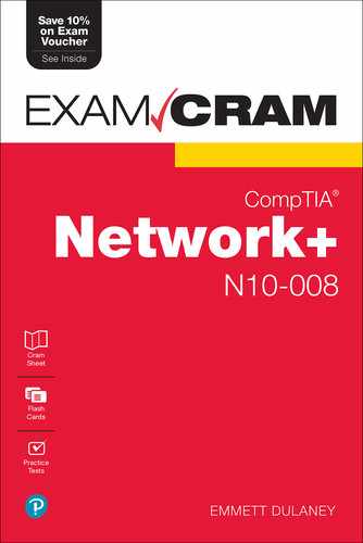
RJ-11 connectors are somewhat similar to RJ-45 connectors, which are discussed next, although they are a little smaller. Both RJ-11 and RJ-45 connectors have a small plastic flange on top of the connector to ensure a secure connection. Figure 5.6 shows two views of an RJ-11 connector.
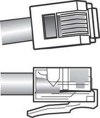
FIGURE 5.6 RJ-11 connectors
RJ-45 Connectors
RJ-45 connectors, as shown in Figure 5.7, are the ones you are most likely to encounter in your network travels. RJ-45 connectors are used with twisted-pair cabling, the most prevalent network cable in use today. RJ-45 connectors resemble the aforementioned RJ-11 phone jacks, but they support up to eight wires instead of the six supported by RJ-11 connectors. RJ-45 connectors are also larger than RJ-11 connectors.

FIGURE 5.7 RJ-45 connectors
F-Type Connectors and RG-59 and RG-6 Cables
F-type connectors, as shown in Figure 5.8, are screw-on connections used to attach coaxial cable to devices. This includes RG-59 and RG-6 cables. In the world of modern networking, F-type connectors are most commonly associated with connecting Internet modems to equipment from a cable or satellite Internet service provider (ISP). However, F-type connectors are also used to connect to some proprietary peripherals.

FIGURE 5.8 F-type connector
F-type connectors have a “nut” on the connection that provides something to grip as the connection is tightened by hand. If necessary, this nut can also be lightly gripped with pliers to aid disconnection.
ExamAlert
For the Network+ exam, you will be expected to identify the connectors discussed in this chapter by their appearance.
Fiber Connectors
A variety of connectors are associated with fiber cabling, and there are several ways of connecting them. They include bayonet, snap-lock, and push-pull connectors. Figure 5.9 shows the fiber connectors identified in the Network+ objectives.
ExamAlert
As with the other connectors discussed in this section, be prepared to identify fiber connectors by their appearance and by how they are physically connected.
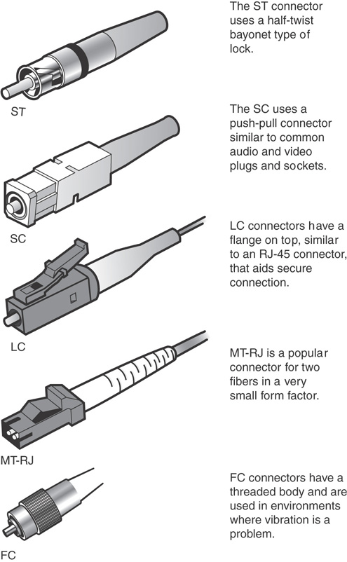
FIGURE 5.9 Fiber connectors
Within the various types of connectors (ST, SC, LC, MT-RJ, and so on), you can choose to purchase ones that are either angled physical contact (APC) or ultra-physical contact (UPC). The biggest difference between these two is the “angle” present in APC. UPC connectors have an endface polished at a zero-degree angle (flat), whereas APC is eight degrees. As a general rule, the more polished (UPC) gives less insertion loss.
MT-RJ (standing for either Mechanical Transfer Registered Jack or Media Termination Recommended Jack) is popular for duplex multimode connections. It is often written with the dash between the letters, but CompTIA prefers to use MTRJ in their objectives and on the exam.
Transceivers
On routers, small form-factor pluggable (SFP) modules and gigabit interface converter (GBIC) modules are often used to link a gigabit Ethernet port with a fiber network (often 1000BASE-X). Both SFPs and GBICs exist for technologies other than fiber (Ethernet and SONET/SDH are usual), but connecting to fiber has become the most common use.
Note
SFP+ is an enhanced small form-factor pluggable module; it is a newer version of SFP that supports data rates up to 16 Gbps. Quad Small Form-factor Pluggable (QSFP) is a different transceiver that is both compact and hot-pluggable; it has been jointly developed by many networking vendors. Similarly, Enhanced QSFP+ is an evolution of QSFP that supports four channels.
Fiber transceivers are bidirectional and capable of operating in duplex mode. With either an SFP or GBIC, there is a receiver port (RX) and transmitter port (TX). These devices are static-sensitive as well as dust-sensitive, and dirty connectors can cause intermittent problems. Care should be taken to not remove them more often than absolutely necessary to keep from shortening their life. After a module goes bad, they can be swapped for a new one to resolve the problem.
Note
Cisco has a great post on the care and maintenance of SFPs at www.cisco.com/en/US/products/hw/modules/ps4999/products_tech_note09186a00807a30d6.shtml.
Signal loss can occur not only from unclean connectors, but also from connector mismatch. Improper alignment and differences in core diameters contribute to signal loss.
When troubleshooting an SFP or GBIC, you should make sure that you do not have a cable mismatch or a bad cable/transceiver. As simple as it may sound, it is important to verify that you are using a single-mode fiber with a single-mode interface and a multimode fiber cable for a multimode interface. Such a fiber type mismatch can cause the physical link to go completely down but does not always do so, thus making troubleshooting it difficult.
Media Couplers/Converters
When you have two dissimilar types of network media, a media converter is used to allow them to connect. They are sometimes referred to as couplers. Depending on the conversion being done, the converter can be a small device barely larger than the connectors themselves or a large device within a sizable chassis.
Reasons for not using the same media throughout the network, and thus reasons for needing a converter, can range from cost (gradually moving from coax to fiber), disparate segments (connecting the office to the factory), or needing to run a particular media in a setting (the need for fiber to reduce EMI problems in a small part of the building).
Figure 5.10 shows an example of a media converter. The one shown converts between 10/100/1000TX and SFP.

FIGURE 5.10 A common media converter
The following converters are commonly implemented and ones that CompTIA includes on the Network+ exam.
ExamAlert
Make sure you know that the possibilities listed here exist.
 Single mode fiber to Ethernet
- Single mode to multimode fiber
- Multimode fiber to Ethernet
- Fiber to coaxial
TIA/EIA 568A and 568B Wiring Standards
568A and 568B are telecommunications standards from TIA and EIA. These 568 standards specify the pin arrangements for the RJ-45 connectors on UTP or STP cables. The number 568 refers to the order in which the wires within the cable are terminated and attached to the connector.
The TIA/EIA 568A and 568B standards (often referred to as T568A and T568B for termination standard) are similar; the difference is the order in which the pins are terminated. The signal is the same for both. Both are used for patch cords in an Ethernet network.
ExamAlert
The only notable difference between T568A and T568B is that pairs 2 and 3 (orange and green) are swapped.
Network media might not always come with connectors attached, or you might need to make custom length cables. This is when you need to know something about how these standards actually work. Before you can crimp on the connectors, you need to know in which order the individual wires will be attached to the connector. Figure 5.11 shows the pin number assignments for the T568A and T568B standards.
FIGURE 5.11 Pin assignments for the T568A and T568B standards
Straight-Through Versus Crossover Cables
Two types of cables are used to connect devices to hubs and switches: crossover cables and straight-through cables. The difference between the two types is that in a crossover cable, two of the wires are crossed; in a straight-through cable, all the wires run straight through.
Specifically, in a crossover cable, wires 1 and 3 and wires 2 and 6 are crossed. Wire 1 at one end becomes wire 3 at the other end, wire 2 at one end becomes wire 6 at the other end, and vice versa in both cases. You can see the differences between the two cables in Figures 5.12 and 5.13. Figure 5.12 shows the pinouts for a straight-through cable, and Figure 5.13 shows the pinouts for a crossover cable.
ExamAlert
The crossover cable can be used to directly network two PCs without using a hub or switch. This is done because the cable performs the function of the switch.

FIGURE 5.12 Pinouts for a straight-through twisted-pair cable
Note
Auto MDI-X ports on newer interfaces detect whether the connection requires a crossover and automatically choose the MDI or MDI-X configuration to match the other end of the link.
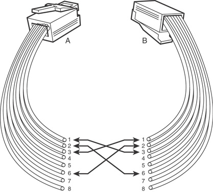
FIGURE 5.13 Pinouts for a crossover twisted-pair cable
To make a crossover Ethernet cable, you need to use both the 568A and 568B standards. One end of the cable can be wired according to the 568A standard and the other with the 568B standard.
A T1 crossover cable, the pinouts of which are shown in Figure 5.14, is used to connect two T1 CSU/DSU devices in a back-to-back configuration. RJ-45 connectors are used on both ends.

FIGURE 5.14 Pinouts for a T1 crossover cable
Rollover and Loopback Cables
The rollover cable is a Cisco proprietary cable used to connect a computer system to a router or switch console port. The rollover cable resembles an Ethernet UTP cable; however, it is not possible to use it on anything but Cisco equipment. Like UTP cable, the rollover cable has eight wires inside and an RJ-45 connector on each end that connects to the router and the computer port.
As far as pinouts are concerned, pin 1 on one end of the rollover cable connects to pin 8 at the other end of the cable. Similarly, pin 2 connects to pin 7, and so on. The ends are simply reversed. As soon as one end of the rollover cable is connected to the PC and the other to the Cisco terminal, the Cisco equipment can be accessed from the computer system using a program such as PuTTY.
ExamAlert
Remember that the rollover cable is a proprietary cable used to connect a PC to a Cisco router.
A loopback cable, also known as a plug, is used to test and isolate network problems. If made correctly, the loopback plug causes the link light on a device such as a network interface card (NIC) to come on. This is a quick and cheap way to test simple network cabling problems. The loopback plug redirects outgoing data signals to the system. The system then believes that it is both sending and receiving data.
The loopback cable is basically a troubleshooting tool used to test the device to see if it is sending and receiving properly. It uses UTP cable and RJ-45 connectors.
ExamAlert
Know that a loopback cable is a basic troubleshooting tool.
Components of Wiring Distribution
So far, this chapter has examined various types of media and the associated connectors. This section looks at wiring in the closet, the place in networks where you connect the cables and networking devices. These rooms have many names, including the wiring closet, the telecommunications room, and the network operations center (NOC). These telecommunications rooms contain the key network devices, such as the hubs, routers, switches, and servers. These rooms also contain the network media, such as patch cables that connect network devices to horizontal cables and the rest of the network.
Network Cross-Connects
The cable that runs throughout a network can be divided into two distinct sections:
- Horizontal cabling: Connects client systems to the network
- Vertical (backbone) cabling: Runs between floors to connect different locations on the network
Both of these cable types have to be consolidated and distributed from a location—a wiring closet.
Following are three types of cable distribution:
- Vertical or main cross-connect: The location where outside cables enter the building for distribution. This can include Internet and phone cabling.
- Horizontal cross-connect: The location where the vertical and horizontal connections meet.
- Intermediate cross-connect: A type typically used in larger networks. It provides an intermediate cross-connect between the main and horizontal cross-connects.
The term cross-connect refers to the point where the cables running throughout the network meet and are connected.
Horizontal Cabling
Within the telecommunications room, horizontal cabling connects the telecommunications room to the end user, as shown in Figure 5.15. Specifically, the horizontal cabling extends from the telecommunications outlet, or a network outlet with RJ-45 connectors, at the client end. It includes all cable from that outlet to the telecommunications room to the horizontal cross-connect—the distribution point for the horizontal cable. The horizontal cross-connect includes all connecting hardware, such as patch panels and patch cords. The horizontal cross-connect is the termination point for all network horizontal cables.

FIGURE 5.15 Horizontal cabling
Horizontal cabling runs within walls and ceilings and therefore is called permanent cable or structure cable. The length of cable running from the horizontal connects and the telecommunication outlet on the client side should not exceed 90 meters. Patch cables used typically should not exceed 5 meters because of the 100-meter distance limitation of most UTP cable.
Note
Horizontal wiring includes all cabling run from the wall plate or network connection to the telecommunications closet. The outlets, cable, and cross-connects in the closet are all part of the horizontal wiring, which gets its name because the cable typically runs horizontally above ceilings or along the floor.
Vertical Cables
Vertical cable, or backbone cable, refers to the media used to connect telecommunications rooms, server rooms, and remote locations and offices. Vertical cable may be used to connect locations outside the local LAN that require high-speed connections. Therefore, vertical cable is often fiber-optic cable or high-speed UTP cable. Figure 5.16 shows the relationship between horizontal cable and vertical cable.

FIGURE 5.16 Vertical and horizontal cabling
Patch Panels
If you have ever looked in a telecommunications room, you have probably seen a distribution block, more commonly called a patch panel. A patch panel is a freestanding or wall-mounted unit with a number of RJ-45 port connections on the front. In a way, it looks like a wall-mounted hub without the light-emitting diodes (LEDs). The patch panel provides a connection point between network equipment, such as hubs and switches, and the ports to which PCs are connected, which normally are distributed throughout a building.
Note
Not all environments use patch panels. In some environments, cables run directly between systems and a hub or switch. This is an acceptable method of connectivity, but it is not as easy to make tidy as a structured cabling system that uses a patch panel system and wall or floor sockets.
Also found in a wiring closet is the punchdown block. The wires from a telephony or UTP cable are attached to the punchdown block using a punchdown tool. To use the punchdown tool, you place the wires in the tip of the tool and push it into the connectors attached to the punchdown block. The wire insulation is stripped, and the wires are firmly embedded into the metal connector. Because the connector strips the insulation on the wire, it is known rather grandiosely as an insulation displacement connector (IDC). Figure 5.17 shows a punchdown tool used for placing wires into a patch panel.

FIGURE 5.17 Punchdown tool
Using a punchdown tool is much faster than using wire strippers to prepare each individual wire and then twisting the wire around a connection pole or tightening a screw to hold the wire in place. In many environments, cable tasks are left to a specialized cable contractor. In others, the administrator is the one who must connect wires to a patch panel.
ExamAlert
Punchdown tools are used to attach twisted-pair network cable to connectors within a patch panel. Specifically, they connect twisted-pair wires to the IDC.
Fiber Distribution Panels
Just as a patch panel is used to provide a connection point between network equipment, so too is a fiber distribution panel (FDP). The difference between the two is that the FDP is a cabinet intended to provide space for termination, storage, and splicing of fiber connections.
ExamAlert
As you study for the exam, make sure you can identify the following exam objectives discussed here and the following: termination points, 66 block, 110 block, patch panel, and fiber distribution panel.
66 and 110 Blocks (T568A, T568B)
Two main types of punchdown blocks are used: type 66 and type 110. Type 66 is an older design used to connect wiring for telephone systems and other low-speed network systems and is not as widely used as type 110. The 66 block has 50 rows of IDC contacts to accommodate 25-pair twisted-pair cable. Block 66 was used primarily for voice communication. Although it was approved for Category 5 and greater, it is not really suitable for anything greater than 10BASE-T due to crosstalk problems. However, specialized certified blocks are available that do meet Cat 5e or Cat T6 termination standards.
In the network wiring closet, the 110 block is used to connect network cable to patch panels. The 110 connections can also be used at the other end of the network cable at the RJ-45 wall jack. The 110 blocks are preferred over the older 66 blocks because the 110 block improves on the 66 block by supporting higher frequencies and less crosstalk. Therefore, it supports higher-speed networks and higher-grade twisted-pair cable. The termination will be T568A or T568B, depending on which wiring standard is used.
In addition to 66 and 110 blocks, Krone and Bix blocks also exist. These two require different blades in the punchdown tools (Krone, for example, requires a separate scissor-like mechanism for trimming the wire) to work with them. Bix (Building Industry Cross-connect) is certified for Cat 5e and Cat 6. Bix is popular in older implementations and Krone is more popular internationally.
MDF and IDF Wiring Closets
The preceding section looked at wiring closets. Two types of wiring closets are main distribution frame (MDF) and intermediate distribution frame (IDF). The main wiring closet for a network typically holds the majority of the network gear, including routers, switches, wiring, servers, and more. This is also typically the wiring closet where outside lines run into the network. This main wiring closet is known as the MDF. One of the key components in the MDF is a primary patch panel. The network connector jacks attached to this patch panel lead out to the building for network connections.
In some networks, multiple wiring closets are used. When this is the case, the MDF connects to these secondary wiring closets, or IDFs, using a backbone cable. This backbone cable may be UTP, fiber, or even coaxial. In today’s high-speed networks, UTP Gigabit Ethernet or high-speed fiber are the media of choice. Figure 5.18 shows the relationship between the MDF and the IDF.
ExamAlert
Be prepared to identify the difference between an IDF and an MDF. They are addressed in objective 3.2 and covered in Chapter 8, “Network Operations.”

FIGURE 5.18 The relationship between MDFs and IDFs
Ethernet Copper and Fiber Standards
A number of IEEE standards relate to networking and cover everything from implementation to security. The 802.3 standards relate to Ethernet deployment, and many of the early ones have become outdated. Make sure that you are familiar with the information that follows for the most popular standards presently before you take the Network+ exam.
10BASE-T
The 10BASE-T standard specifies an Ethernet network that commonly uses unshielded twisted-pair cable. In some implementations that require a greater resistance to interference and attenuation, STP can be used because it has extra shielding and is more able to combat interference.
ExamAlert
Hyphens have no meaning when it comes to wiring standards; 10BASE-T is the same as 10BaseT. Because CompTIA uses the hyphen in this round of objectives, this book does as well. Know that both notations mean the same thing.
The 10BASE-T standard uses broadband transmission and has a maximum physical segment length of 100 meters. Repeaters are sometimes used to extend the maximum segment length, although the repeating capability is now often built into networking devices used in twisted-pair networks. 10BASE-T specifies transmission speeds of 10 Mbps and can use several categories of UTP cable with RJ-45 connectors. The maximum number of computers supported on a 10BASE-T network is 1,024.
100BASE-TX
At one time, 10 Mbps networks were considered fast enough, but those days are long gone. Today, companies and home users alike demand more bandwidth than that, and 100BASE-TX transmits network data at speeds up to 100 Mbps. 100BASE-TX is most often implemented with UTP cable, but it can use STP; therefore, it suffers from the same 100-meter distance limitations as other UTP-based networks. 100BASE-TX uses Category 5, or higher, UTP cable, and it uses independent transmit and receive paths and therefore can support full-duplex operation. 100BASE-TX is the most common implementation of the Fast Ethernet (802.3u) standard.
Tip
Repeaters are sometimes needed when you connect segments that use 100BASE-TX or 100BASE-FX.
A counterpart to 100BASE-TX is 100BASE-FX, which is the IEEE standard for running Fast Ethernet over fiber-optic cable. Due to the expense of fiber implementations, 100BASE-FX is largely limited to use as a network backbone. 100BASE-FX can use two-strand multimode fiber or single-mode fiber media. The maximum segment length for half-duplex multimode fiber is 412 meters, but this maximum increases to an impressive 10,000 meters for full-duplex single-mode fiber. 100BASE-FX often uses SC or ST fiber connectors. Table 5.3 summarizes the characteristics of the 802.3u Fast Ethernet specifications.
TABLE 5.3 Summary of 802.3u Fast Ethernet Characteristics
Characteristic |
100BASE-TX |
100BASE-FX |
|---|---|---|
Transmission method |
Baseband |
Baseband |
Speed |
100 Mbps |
100 Mbps |
Distance |
100 meters |
412 meters (multimode half duplex); 10,000 meters (single-mode full duplex) |
Cable type |
Category UTP, STP |
Fiber-optic |
Connector type |
RJ-45 |
SC, ST |
An additional fiber option, 100BASE-SX, is considered a lower-cost alternative to 100BASE-FX. It uses LEDs instead of lasers and can be used for shorter distances (up to 300 meters).
1000BASE-T
The Gigabit Ethernet standard 1000BASE-T, or 1000BASE-TX, is given the IEEE 802.3ab designation. The 802.3ab standard specifies Gigabit Ethernet over Category 5 or better UTP cable. The standard allows for full-duplex transmission using the four pairs of twisted cable. To reach speeds of 1000 Mbps over copper, a data transmission speed of 250 Mbps is achieved over each pair of twisted-pair cable. Table 5.4 summarizes the characteristics of 1000BASE-T.
TABLE 5.4 Summary of 1000BASE-T Characteristics
Characteristic |
Description |
|---|---|
Transmission method |
Baseband |
Speed |
1000 Mbps |
Total distance/segment |
75 meters |
Cable type |
Category 5 or better |
Connector type |
RJ-45 |
10GBASE-T
The 802.3an standard brings 10-gigabit speed to regular copper cabling. Although transmission distances may not be that of fiber, it allows a potential upgrade from 1000 Mbps networking to 10 Gbps networking using the current wiring infrastructure.
The 10GBASE-T standard specifies 10 Gbps transmissions over UTP or STP twisted-pair cables. The standard calls for a cable specification of Category 6 or Category 6a. With Category 6, the maximum transmission range is 55 meters; with the augmented Category 6a cable, transmission range increases to 100 meters. Category 6 and 6a cables are specifically designed to reduce attenuation and crosstalk, making 10 Gbps speeds possible. The 802.3an standard specifies regular RJ-45 networking connectors. Table 5.5 outlines the characteristics of this standard.
TABLE 5.5 Summary of 802.3an Characteristics
Characteristic |
Descriptions |
|---|---|
Transmission method |
Baseband |
Speed |
10 Gbps |
Total distance/segment |
100 meters Category 6a cable; 55 meters Category 6 cable |
Cable type |
Category 6, 6a UTP or STP |
Connector |
RJ-45 |
40GBASE-T
The 40GBASE-T standard provides for 4-pair balanced (40 Gbps on 4-twisted pairs cable) twisted-pair Category 8 copper cabling up to 30 meters. It is defined in the IEEE 802.3bq standard it is expected to be used primarily within datacenters.
Table 5.6 outlines the characteristics of the 802.3bq standard.
TABLE 5.6 Summary of 802.3bq Characteristics
Characteristic |
Descriptions |
|---|---|
Transmission method |
Baseband |
Speed |
40 Gbps |
Total distance/segment |
30 meters Category 8 cable |
Cable type |
Category 8 |
Connector |
RJ-45 |
1000BASE-LX and 1000BASE-SX
Both 1000BASE-LX and 1000BASE-SX are Gigabit Ethernet standards for fiber.
As a fiber standard for Gigabit Ethernet, 1000BASE-LX utilizes single-mode fiber. It can also run over multimode fiber with a maximum segment length of 550m.
The 1000BASE-SX standard is intended for use with multimode fiber and has a maximum length of 220 meters for default installations (550 meters is possible with the right optics and terminations). This standard is popular for intrabuilding links in office buildings.
10GBASE-LR and 10GBASE-SR
The 10GBASE-LR standard is easy to remember in that the LR stands for long range: the maximum fiber length is 10 kilometers, but it varies greatly depending on the type of single-mode fiber used. 10GBASE-SR is a multimode fiber intended for the short range (up to 400 meters): it is considered the lowest cost, lowest power, and smallest form factor optical option available at this speed.
Multiplexing Options
Virtual circuits establish a bidirectional communication link between devices and use it for their communication links. Multiplexing was discussed earlier in the “Broadband Versus Baseband Transmissions” section, but you should know that bidirectional wavelength division multiplexing (WDM) is the transmission of optical channels on a fiber propagating simultaneously in both directions.
Several types of WDM multiplexing can be employed during these links. One form of multiplexing optical signals is dense wavelength-division multiplexing (DWDM). This method replaces SONET/SDH regenerators and can amplify the signal and enable it to travel a greater distance. The main components of a DWDM system include the following:
- Terminal multiplexer
- Line repeaters
- Terminal demultiplexer
ExamAlert
Make sure that you understand that DWDM works with SONET/SDH.
An alternative to DWDM is coarse wavelength-division multiplexing (CWDM). This method is commonly used with television cable networks. The main thing to know about it is that it has relaxed stabilization requirements; thus, you can have vastly different speeds for download than upload.
ExamAlert
Make sure that you associate CWDM with television cabling.
Cram Quiz
1. Which of following connectors is commonly used with fiber cabling?
![]() A. RJ-45
A. RJ-45
![]() B. BNC
B. BNC
![]() C. SC
C. SC
![]() D. RJ-11
D. RJ-11
2. What kind of cable would you associate with an F-type connector?
![]() A. Fiber-optic
A. Fiber-optic
![]() B. UTP
B. UTP
![]() C. Coaxial
C. Coaxial
![]() D. STP
D. STP
3. Which of the following is not a type of fiber-optic connector used in network implementations?
![]() A. MTRJ
A. MTRJ
![]() B. SC
B. SC
![]() C. BNC
C. BNC
![]() D. LC
D. LC
4. Which of the following fiber connectors uses a twist-type connection method?
![]() A. ST
A. ST
![]() B. SC
B. SC
![]() C. BNC
C. BNC
![]() D. SA
D. SA
5. Which of the following is a fiber standard for Gigabit Ethernet that utilizes single-mode fiber?
![]() A. 1000BASE-SX
A. 1000BASE-SX
![]() B. TIA/EIA 568a
B. TIA/EIA 568a
![]() C. RG-6
C. RG-6
![]() D. 1000BASE-LX
D. 1000BASE-LX
6. In a crossover cable, which wire is wire 1 crossed with?
![]() A. 2
A. 2
![]() B. 3
B. 3
![]() C. 4
C. 4
![]() D. 5
D. 5
7. What are the main types of punchdown blocks? (Choose two.)
![]() A. 110
A. 110
![]() B. 220
B. 220
![]() C. 66
C. 66
![]() D. 12
D. 12
8. Which of the following are cables that are specifically coated with a nonflammable material and do not give off toxic fumes if they catch fire?
![]() A. SFP and GBIC
A. SFP and GBIC
![]() B. Cat 5e, Cat 6, Cat 6a
B. Cat 5e, Cat 6, Cat 6a
![]() C. FDP
C. FDP
![]() D. Plenum-rated
D. Plenum-rated
Cram Quiz Answers
1. C. SC connectors are used with fiber-optic cable. RJ-45 connectors are used with UTP cable, BNC is used for thin coax cable, and RJ-11 is used for regular phone connectors.
2. C. F-type connectors are used with coaxial cables. They are not used with fiber-optic, unshielded twisted-pair (UTP), or shielded twisted-pair (STP) cabling.
3. C. BNC is a connector type used with coaxial cabling. It is not used as a connector for fiber-optic cabling. MTRJ, SC, and LC are all recognized types of fiber-optic connectors.
4. A. ST fiber connectors use a twist-type connection method. SC connectors use a push-type connection method. The other choices are not valid fiber connectors.
5. D. The 1000BASE-LX fiber standard for Gigabit Ethernet utilizes single-mode fiber. 1000BASE-SX is intended for use with multimode fiber and has a maximum length of 220 meters for default installations. TIA/EIA 568A (and 568B) are telecommunications standards that specify the pin arrangements for the RJ-45 connectors on UTP or STP cables. RG-6 is a common type of coaxial cable often used for cable TV and cable modems.
6. B. In a crossover cable, wires 1 and 3 and wires 2 and 6 are crossed.
7. A, C. The two main types of punchdown blocks are type 66 and type 110. Type 66 is an older design used to connect wiring for telephone systems and other low-speed network systems and is not as widely used as type 110.
8. D. Plenum-rated cables are coated with a nonflammable material, often Teflon or Kynar, and they do not give off toxic fumes if they catch fire. On routers, SFP modules and GBIC modules are often used to link a gigabit Ethernet port with a fiber network. Cat 5, Cat 5e, Cat 6, Cat 6a, and also Cat 7 and Cat 8 are general categories of twisted-pair cabling. FDP is an acronym for fiber distribution panel, which is a cabinet intended to provide space for termination, storage, and splicing of fiber connections.
Troubleshooting Common Cable Connectivity Issues
- Given a scenario, troubleshoot common cable connectivity issues and select the appropriate tools.
ExamAlert
Remember that this objective begins with “Given a scenario.” This means that you may receive a drag and drop, matching, or “live OS” scenario where you have to click through to complete a specific objective-based task.
When administering a wired network, you should be aware of a number of performance issues and common connectivity problems. Some of the topics lumped within this objective are more knowledge/definitions than actionable items, but make sure you are familiar with them all the same. We first look at some limitations, considerations, and issues. Following that, we discuss some of the common tools used by network technicians.
Limitations, Considerations, and Issues
Specifications and issues abound when trying to optimize a network and keep it up and running. It is very rare for resource demands to lessen over time, and they only seem to grow. Keeping up with that growth requires taking a lot into consideration and knowing the limitations of each technology. In the sections that follow, we look at some of the specifications/limitations and common issues associated with them.
Throughput, Speed, and Distance
There must be enough bandwidth to serve all users, and you need to be alert for bandwidth hogs. You want to look for top talkers (those that transmit the most) and top listeners (those that receive the most) and figure out why they are so popular.
In the networking world, throughput refers to the rate of data delivery over a communication channel. In this case, throughput testers test the rate of data delivery over a network. Throughput is measured in bits per second (bps). Testing throughput is important for administrators to make them aware of exactly what the network is doing. With throughput testing, you can tell whether a high-speed network is functioning close to its expected throughput.
A throughput tester is designed to quickly gather information about network functionality—specifically, the average overall network throughput. Many software-based throughput testers are available online—some for free and some for a fee.
As you can see, throughput testers do not need to be complicated to be effective. A throughput tester tells you how long it takes to send data to a destination point and receive an acknowledgment that the data was received. To use the tester, enter the beginning point and then the destination point. The tester sends a predetermined number of data packets to the destination and then reports on the throughput level. The results typically display in kilobits per second (Kbps), megabits per second (Mbps), or gigabits per second (Gbps). Table 5.7 shows the various data rate units.
TABLE 5.7 Data Rate Units
Data Transfer |
Abbreviation |
Speed |
|---|---|---|
Kilobits per second |
Kbps or Kbit/s |
1,000 bits per second |
Megabits per second |
Mbps or Mbit/s |
1,000,000 bits per second |
Gigabits per second |
Gbps or Gbit/s |
1,000,000,000 bits per second |
Kilobytes per second |
KBps |
1,000 bytes per second, or 8 kilobits per second |
Megabytes per second |
MBps |
1,000,000 bytes per second, or 8 megabits per second |
Gigabytes per second |
GBps |
1,000,000,000 bytes per second, or 8 gigabits per second |
Administrators and techs can periodically conduct throughput tests and keep them on file to create a picture of network performance. If you suspect a problem with the network functioning, you can run a test to compare with past performance to see exactly what is happening.
One thing worth mentioning is the difference between throughput and bandwidth. These terms are often used interchangeably, but they have different meanings. When talking about measuring throughput, you measure the amount of data flow under real-world conditions—measuring with possible electromagnetic interference (EMI) influences, heavy traffic loads, improper wiring, and even network collisions. Take all this into account, take a measurement, and you have the network throughput. Bandwidth, in contrast, refers to the maximum amount of information that can be sent through a particular medium under ideal conditions.
Note
Be sure that you know the difference between throughput and bandwidth/speed.
Cabling Specifications/Limitations
Earlier in this chapter, we discussed the cabling types (Cat 7, Cat 8, etc.) that are available. Each of those categories of cables comes with its own limitations for throughput, speed, and distance—the three variables that a network administrator must so often juggle and balance.
Two types of websites that can be invaluable when it comes to networking are speed test sites and looking-glass sites. Speed test sites, as the name implies, are bandwidth speed testers that report the speed of the connection that you have to them and can be helpful in determining if you are getting the rate your ISP has promised.
Looking-glass sites are servers running looking-glass (LG) software that enables you to see routing information. The servers act as a read-only portal giving information about the backbone connection. Most of these servers will show ping information, trace (tracert/traceroute) information, and Border Gateway Protocol (BGP) information.
Cabling Considerations
When you’re considering what cabling option to go with, money is almost always a factor. While the best option is always to use the best cabling and best devices, financial officers often insist that everything be done with in budgetary constraints that prohibit always using the best. This means that you often have to work with what you have and try to keep it up and running cost-efficiently when things go wrong.
Damaged or bad wiring could be a patch cable (easy to replace) or the in-wall wiring (more difficult to replace). If you suspect wiring to be the faulty component, you can diagnose rather quickly by taking the device that is having trouble connecting to another location and/or bringing a working machine to this environment. You can use a multifunction cable tester to troubleshoot most wiring problems. You must check for cable continuity, as well as for shorts.
Note
Never assume that the cable you use is good until you test it and confirm that it is good. Sometimes cables break, and bad media can cause network problems.
Bent pins on a network cable or socket can result in very little or no contact being made on those connections. If the problem is with the cable, you can replace the cable. If the problem is with the client machine, it can be difficult to fix because most Ethernet ports are soldered directly to the motherboard. Often, the solution is to abandon that port and use a USB/Ethernet adapter to allow the client to continue to connect to the network.
Cabling Applications
Cabling can be used for many different scenarios; three common ones are as a crossover cable (used to connect any two devices of the same type), a rollover cable (used to connect a computer terminal to a router’s console port), and a Power over Ethernet (PoE) cable (described in Chapter 3, “Addressing, Routing, and Switching”).
An incorrect cable type—using a crossover cable instead of a standard cable, for instance—will keep the host from being able to communicate on the network. A cable tester can be used to diagnose individual cabling issues, and the solution is to swap the incorrect cable with one suited for the purpose you are intending to use it for.
Attenuation and dB Loss
Attenuation refers to the weakening of data signals as they travel through a medium. Network media vary in their resistance to attenuation. Coaxial cable generally is more resistant than unshielded twisted-pair (UTP); shielded twisted-pair (STP) is slightly more resistant than UTP; and fiber-optic cable does not suffer from attenuation. That’s not to say that a signal does not weaken as it travels over fiber-optic cable, but the correct term for this weakening is chromatic dispersion rather than attenuation.
You must understand attenuation or chromatic dispersion and the maximum distances specified for network media. Exceeding a medium’s distance without using repeaters can cause hard-to-troubleshoot network problems. A repeater is a network device that amplifies data signals as they pass, enabling them to travel farther. Most attenuation-related or chromatic dispersion-related difficulties on a network require using a network analyzer to detect them.
All media have recommended lengths at which the cable can be run. The reason is that data signals weaken as they travel farther from the point of origin. If the signal travels far enough, it can weaken so much that it becomes unusable. The weakening of data signals as they traverse the medium is called attenuation. The measurement of it is done in decibels; thus, attenuation is also known as dB loss.
All copper-based cabling is particularity susceptible to attenuation. When cable lengths have to be run farther than the recommended lengths, signal repeaters can be used to boost the signal as it travels. If you work on a network with intermittent problems, and you notice that cable lengths are run too far, attenuation may be the problem.
ExamAlert
For the Network+ objective referencing cable problems associated with distance, think of attenuation.
Interference
Depending on where network cabling (commonly called media) is installed, interference can be a major consideration. Two types of media interference can adversely affect data transmissions over network media: electromagnetic interference (EMI) and crosstalk (discussed earlier).
EMI is a problem when cables are installed near electrical devices, such as air conditioners or fluorescent light fixtures. If a network medium is placed close enough to such a device, the signal within the cable might become corrupt. Network media vary in their resistance to the effects of EMI. Standard unshielded twisted-pair (UTP) cable is susceptible to EMI, whereas fiber cable, with its light transmissions, is resistant to EMI. When deciding on a particular medium, consider where it will run and the impact EMI can have on the installation.
EMI can reduce or corrupt signal strength. This can happen when cables are run too close to everyday office fixtures, such as computer monitors, fluorescent lights, elevators, microwaves, and anything else that creates an electromagnetic field. Again, the solution is to carefully run cables away from such devices. If they have to be run through EMI areas, shielded cabling or fiber cabling is needed.
Incorrect Pinout
Most splits in a cable are intentional—enabling you to run the wiring in multiple directions with the use of a splitter. Depending on the type of cabling in question, it is not uncommon for each split to reduce the strength of the signal. It is also not uncommon for splitters to go bad. You should split the cable as few times as possible and check the splitter if a problem in a run that was normally working suddenly occurs.
If the split is unintentional, you are often dealing with an open/short, which is discussed later.
Bad Ports
On the router, the port configuration dictates what traffic is allowed to flow through. The router can be configured to enable individual port traffic in, out, or both and is referred to as port forwarding. If a port is blocked (such as 80 for HTTP or 21 for FTP), the data will not be allowed through, and users will be affected.
ExamAlert
Think of port configuration and port forwarding as the same when it comes to the router.
A condition known as a black hole can occur when a router does not send back an expected message that the data has been received. It is known as a black hole from the view that data is being sent, but is essentially being lost.
This condition occurs when the packet the router receives is larger than the configured size of the maximum transmission unit (MTU) and the Don’t Fragment flag is configured on that packet. When this condition occurs, the router is supposed to send a “Destination Unreachable” message back to the host. If the packet is not received, the host does not know that the packet did not go through.
Although there are several solutions to this problem, the best is to verify whether a mismatch has occurred between the maximum size packet that clients can send and that the router can handle. You can use ping to check that packets of a particular size can move through the router by using the -l parameter to set a packet size and the -f parameter to set the Do Not Fragment bit.
Open/Short
In addition to the common issue of miswiring, other problems that can occur with cables (and that can be checked with a multifunction cable tester) include open/short faults. An open fault means that the cables are not making a full circuit; this can be due to a cut in the cable (across all or some of the wires). A short fault means that the data attempts to travel on wires other than those for which it is intended; this can be caused by miswiring or a twist in the cabling at a cut allowing the bare wires to touch.
ExamAlert
You should expect questions asking you what tool can be used to identify an open/short fault.
LED Status Indicators
Hubs and switches provide light-emitting diodes (LEDs) that provide information on the port status. For instance, by using the LEDs, you can determine whether there is a jabbering network card, whether there is a proper connection to the network device, and whether there are too many collisions on the network.
Incorrect Transceivers
When troubleshooting an SFP or GBIC, you should make sure that you do not have a bad, or mismatched, transceiver. As simple as this advice may sound, it is important to verify that you are using a single-mode fiber with a single-mode interface and a multimode fiber cable for a multimode interface. Such a fiber type mismatch can cause the physical link to go completely down but does not always do so, thus making troubleshooting it difficult.
Duplexing Issues
When configuring a client for the network, you must be aware of two settings: port speed and duplex settings. They are adjusted in Windows in the Network Properties area. Speed and duplex mismatches can slow data rates to a crawl and prevent high-bandwidth applications (such as voice or streaming video) from being possible.
You have several choices for port speed and duplex settings as Figure 5.19 illustrates. You can choose Auto Negotiation to detect the setting that the network uses. You also can choose one of the other settings to match the network configuration, such as 100 Mbps Half Duplex. If you work with a client system that is unable to log on to a network, you might need to ensure that the duplex setting and port speeds are correctly set for the network.

FIGURE 5.19 Configuring speed and duplex options
TX/RX Reversed
Two primary types of cables can be used in an Ethernet network: a straight-through cable (as the name implies, all wires run straight through and are the same on both ends) and a crossover cable. In a crossover cable, two pairs of the wires are reversed; these are the TX and RX pairs (transmit and receive).
A crossover cable is intended to be used in specific applications only (such as to directly network two PCs without using a hub or switch) and will cause problems when used where a straight-through cable is called for (as a general rule, in all fixed wiring).
Dirty Optical Cables
Dirty fiber cables—or, more commonly, connector—can cause a slowdown in traffic due to the need to be able to clearly transmit light. The “dirty” can be caused by exposure to liquids, dust, or other contaminants. Isopropyl alcohol can be used if wet cleaning is necessary (where it is not possible to simply blow away the dust).
Common Tools
A large part of network administration involves having the right tools for the job and knowing when and how to use them. Selecting the correct tool for a networking job sounds like an easy task, but network administrators can choose from a mind-boggling number of tools and utilities.
Given the diverse range of tools and utilities available, it is unlikely that you will encounter all the tools available—or even all those discussed in this chapter. For the Network+ exam, you are required to have general knowledge of the tools available and what they are designed to do.
Until networks become completely wireless, network administrators can expect to spend some of their time using a variety of media-related troubleshooting and installation tools. Some of these tools (such as the tone generator and locator) may be used to troubleshoot media connections, and others (such as wire crimpers and punchdown tools) are used to create network cables and connections.
Cable Crimpers, Strippers, and Snips/Cutters
Wire crimpers, also known as cable crimpers, are tools you might regularly use. Like many things, making your own cables can be fun at first, but the novelty soon wears off. Basically, a wire crimper is a tool that you use to attach media connectors to the ends of cables. For instance, you use one type of wire crimper to attach RJ-45 connectors on unshielded twisted-pair (UTP) cable. You use a different type of wire crimper to attach British Naval Connectors/Bayonet Neill-Concelman (BNCs) to coaxial cabling.
Tip
When making cables, always order more connectors than you need; a few mishaps will probably occur along the way.
In a sense, you can think of a wire crimper as a pair of special pliers. You insert the cable and connector separately into the crimper, making sure that the wires in the cable align with the appropriate connectors. Then, by squeezing the crimper’s handles, you force metal connectors through the cable’s wires, making the connection between the wire and the connector.
When you crimp your own cables, you need to be sure to test them before putting them on the network. It takes only a momentary lapse to make a mistake when creating a cable, and you can waste time later trying to isolate a problem in a faulty cable.
Two other commonly used wiring tools are strippers and snips/cutters. Wire strippers come in a variety of shapes and sizes. Some are specifically designed to strip the outer sheathing from coaxial cable, and others are designed to work best with UTP cable. All strippers are designed to cleanly remove the sheathing from wire to make sure a clean contact can be made.
Many administrators do not have specialized wire strippers unless they do a lot of work with copper-based wiring. However, standard wire strippers are good things to have on hand.
Wire snips, also known as wire cutters, are tools designed to cleanly cut the cable. Sometimes network administrators buy cable in bulk and use wire snips to cut the cable into desired lengths. The wire strippers are then used to prepare the cable for the attachment of the connectors.
Punchdown Tools
As discussed in the section titled “Patch Panels” earlier in this chapter, punchdown tools are used to attach twisted-pair network cable to connectors within a patch panel. Specifically, they connect twisted-pair wires to the insulation displacement connector (IDC).
Tone Generator
A toner probe is a device that can save a network installer many hours of frustration. This device has two parts: the tone generator, or toner, and the tone locator, or probe. The toner sends the tone, and at the other end of the cable, the probe receives the toner’s signal. This tool makes it easier to find the beginning and end of a cable. You might hear the tone generator and tone locator referred to as the fox and hound.
As you might expect, the purpose of the tone probe is to generate a signal that is transmitted on the wire you are attempting to locate. At the other end, you press the probe against individual wires. When it makes contact with the wire that has the signal on it, the locator emits an audible signal or tone.
The tone locator probe is a useful device, but it does have some drawbacks. First, it often takes two people to operate: one at each end of the cable. Of course, one person could just keep running back and forth, but if the cable is run over great distances, this can be a problem. Second, using the toner probe is time consuming because it must be attached to each cable independently.
Note
Many problems that can be discovered with a tone generator are easy to prevent by taking the time to properly label cables. If the cables are labeled at both ends, you will not need to use such a tool to locate them.
Note
Toner probes are specifically used to locate cables hidden in floors, ceilings, or walls and to track cables from the patch panels to their destinations.
Loopback Adapter
A number of items fall under the loopback umbrella, and all of them serve the same purpose: they allow you to test a device/configuration/connectivity component using a dummy. The most popular loopback is the address used with ping (discussed later in this chapter), but Windows also includes a loopback adapter, which is a dummy network card (no hardware) used for testing a virtual network environment.
Various loopback adapters—actual hardware—can be purchased and used to test Ethernet jacks, fiber jacks, and so on.
OTDR
A time-domain reflectometer (TDR) is a device used to send a signal through a particular medium to check the cable’s continuity. Good-quality TDRs can locate many types of cabling faults, such as a severed sheath, damaged conductors, faulty crimps, shorts, loose connectors, and more. Although network administrators will not need to use a tool such as this every day, it could significantly help in the troubleshooting process. TDRs help ensure that data sent across the network is not interrupted by poor cabling that may cause faults in data delivery.
Note
TDRs work at the physical layer of the OSI model, sending a signal through a length of cable, looking for cable faults.
Because the majority of network cabling is copper based, most tools designed to test cabling are designed for copper-based cabling. However, when you test fiber-optic cable, you need an optical tester.
An optical cable tester performs the same basic function as a wire media tester, but on optical media. The most common problem with an optical cable is a break in the cable that prevents the signal from reaching the other end. Due to the extended distances that can be covered with fiber-optic cables, degradation is rarely an issue in a fiber-optic LAN environment.
Ascertaining whether a signal reaches the other end of a fiber-optic cable is relatively easy, but when you determine that there is a break, the problem becomes locating the break. That’s when you need a tool called an optical time-domain reflectometer (OTDR). By using an OTDR, you can locate how far along in the cable the break occurs. The connection on the other end of the cable might be the source of the problem, or perhaps there is a break halfway along the cable. Either way, an OTDR can pinpoint the problem.
Unless you work extensively with fiber-optic cable, you are unlikely to have an OTDR or even a fiber-optic cable tester in your toolbox. Specialized cabling contractors will have them, though, so knowing they exist is important.
You can use a light meter to certify and troubleshoot fiber. A light source is placed on one end, and the light meter is used at the opposite end to measure loss.
Multimeter
One of the simplest cable-testing devices is a multimeter. By using the continuity setting, you can test for shorts in a length of coaxial cable. Or if you know the correct cable pinouts and have needlepoint probes, you can test twisted-pair cable.
A basic multimeter combines several electrical meters into a single unit that can measure voltage, current, and resistance. Advanced models can also measure temperature.
A multimeter has a display, terminals, probes, and a dial to select various measurement ranges. A digital multimeter has a numeric digital display, and an analog has a dial display. Inside a multimeter, the terminals are connected to different resistors, depending on the range selected.
Network multimeters can do much more than test electrical current:
- Ping specific network devices: A multimeter can ping and test response times of key networking equipment, such as routers, DNS servers, DHCP servers, and more.
- Verify network cabling: You can use a network multimeter to isolate cable shorts, split pairs, and other faults.
- Locate and identify cable: Quality network multimeters enable administrators to locate cables at patch panels and wall jacks using digital tones.
- Documentation ability: Multimeter results can be downloaded to a PC for inspection. Most network multimeters provide a means such as USB ports to link to a PC.
Cable Tester
A media tester, also called a cable tester, defines a range of tools designed to test whether a cable properly works. Any tool that facilitates the testing of a cable can be deemed a cable tester. However, a specific tool called a media tester enables administrators to test a segment of cable, looking for shorts, improperly attached connectors, or other cable faults. All media testers tell you whether the cable works correctly and where the problem in the cable might be.
Generically, the phrase line tester can be used for any device that tests a media line. Although products are available that are Ethernet line testers, fiber line testers, and so on, most often a “line tester” is used to check telephone wiring and usually includes RJ-11 plugs as well as alligator clips.
A cable certifier is a type of tester that enables you to certify cabling by testing it for speed and performance to see that the implementation will live up to the ratings. Most stress and test the system based on noise and error testing. You need to know that the gigabit cable you think you have run is actually providing that speed to the network.
Wire Map
A wire map (sometimes called a wiremap, without the space between the words) is a test (when run, called wire mapping) to see that all Ethernet wiring is correct and there are no opens, shorts, or wires reversed on one end.
Tap
A tap is used to connect drop cables to a distribution cable much like a splitter. The difference between a tap and a splitter is that the splitter sends the incoming signal out to all paths equally, whereas a tap can apply a different amount of loss to each output path individually. This way, if you have one short path and one long path coming off the tap, the strength of the signal received by the host at the end of each path can be close to the same.
Fusion Splicer
A fusion splicer is an expensive tool used to join two optical cables. The splicing is typically done by an electric arc but could also be a laser or a flame. It is important that the splice be as undetectable as possible in order to keep from scattering or reflecting light as it passes through the splice and reducing the quality of the transmission.
Spectrum Analyzer
A spectrum analyzer measures the magnitude of an input signal versus frequency within the full frequency range of the instrument and can be used for a wide range of signals. Today, they are commonly used with Wi-Fi to reveal Wi-Fi hotspots and detect wireless network access with LED visual feedback. Such devices can be configured to scan specific frequencies. When working with 802.11b/g/n/ac/ax networks, you will most certainly require scanning for 2.4 GHz or 5 GHz RF signals.
Such devices can be used in the troubleshooting process to see where and how powerful RF signals are. Given the increase in wireless technologies, RF detectors are sure to continue to increase in popularity.
Fiber Light Meter
A fiber light meter measures the light moving through an optical fiber to look for problems with a cable. To use the meter, you connect one end of the fiber to a light source and put the meter on the other end. The meter reads the light it receives and determines the amount of signal loss, if any.
Cram Quiz
1. Which of the following describes the loss of signal strength as a signal travels through a particular medium?
![]() A. Attenuation
A. Attenuation
![]() B. Crosstalk
B. Crosstalk
![]() C. EMI
C. EMI
![]() D. Chatter
D. Chatter
2. A user calls to report that he is experiencing periodic problems connecting to the network. Upon investigation, you find that the cable connecting the user’s PC to the switch is close to a fluorescent light fixture. What condition is most likely causing the problem?
![]() A. Crosstalk
A. Crosstalk
![]() B. EMI
B. EMI
![]() C. Attenuation
C. Attenuation
![]() D. Faulty cable
D. Faulty cable
3. Which of the following is similar to latency but differs in that the length of the delay between received packets differs?
![]() A. Slack
A. Slack
![]() B. Jitter
B. Jitter
![]() C. Stretch
C. Stretch
![]() D. Lax
D. Lax
4. With a crossover cable, which two pairs are reversed?
![]() A. RX and SX
A. RX and SX
![]() B. TX and RX
B. TX and RX
![]() C. SX and TX
C. SX and TX
![]() D. SX and CX
D. SX and CX
5. While you were away, an air conditioning unit malfunctioned in a server room, and some equipment overheated. Which of the following would have alerted you to the problem?
![]() A. Multimeter
A. Multimeter
![]() B. Environmental monitor
B. Environmental monitor
![]() C. TDR
C. TDR
![]() D. OTDR
D. OTDR
6. What tool would you use when working with an IDC?
![]() A. Wire crimper
A. Wire crimper
![]() B. Media tester
B. Media tester
![]() C. OTDR
C. OTDR
![]() D. Punchdown tool
D. Punchdown tool
7. As a network administrator, you work in a wiring closet where none of the cables have been labeled. Which of the following tools are you most likely to use to locate the physical ends of the cable?
![]() A. Toner probe
A. Toner probe
![]() B. Wire crimper
B. Wire crimper
![]() C. Punchdown tool
C. Punchdown tool
![]() D. ping
D. ping
8. You are installing a new system into an existing star network, and you need a cable that is 45 feet long. Your local vendor does not stock cables of this length, so you are forced to make your own. Which of the following tools do you need to complete the task?
![]() A. Optical tester
A. Optical tester
![]() B. Punchdown tool
B. Punchdown tool
![]() C. Crimper
C. Crimper
![]() D. UTP splicer
D. UTP splicer
Cram Quiz Answers
1. A. The term used to describe the loss of signal strength for media is attenuation. Crosstalk refers to the interference between two cables, EMI is electromagnetic interference, and chatter is not a valid media interference concern.
2. B. EMI is a type of interference that is often seen when cables run too close to electrical devices. Crosstalk is when two cables interfere with each other. Attenuation is a loss of signal strength. Answer D is incorrect also. It may be that a faulty cable is causing the problem. However, the question asked for the most likely cause. Because the cable is running near fluorescent lights, the problem is more likely associated with EMI.
3. B. Jitter is when the length of the delay between received packets differs.
4. B. In a crossover cable, two pairs of the wires are reversed; these are the TX and RX pairs (transmit and receive).
5. B. Environmental monitors are used in server and network equipment rooms to ensure that the temperature does not fluctuate too greatly. In the case of a failed air conditioner, the administrator is alerted to the drastic changes in temperature. Multimeters, TDRs, and OTDRs are used to work with copper-based media.
6. D. You use a punchdown tool when working with an IDC. All the other tools are associated with making and troubleshooting cables; they are not associated with IDCs.
7. A. The toner probe tool, along with the tone locator, can be used to trace cables. Crimpers and punchdown tools are not used to locate a cable. The ping utility would be of no help in this situation.
8. C. When you’re attaching RJ-45 connectors to UTP cables, the wire crimper is the tool you use. None of the other tools listed are used in the construction of UTP cable.
What’s Next?
This chapter focused on wiring solutions. Chapter 6, “Wireless Solutions and Issues,” looks at wireless solutions. Client systems communicate with a wireless access point using wireless LAN adapters. Such adapters are built into or can be added to laptops, handhelds, desktop computers, and even IoT devices. Wireless LAN adapters provide the communication point between the client system and the airwaves via an antenna.