
BUILD TECHNIQUES
Now it is time to talk about how to build a sound system. Modern sound systems are incredibly complex and often have thousands of pieces of equipment. It is not something you simply slap together. It takes lots of planning and preparation. It takes lots of drawings and research. It takes knowledge of how to build a system so you can visualize the system and order all of the parts and pieces. It takes an attention to details and a flexibility to know that everything will change. It takes patience, and if it is done correctly then you will have nothing to do at the shop other than slap labels on equipment and plug it together.
The absolute most important part of the build is the paperwork. There are some standards in the business, but not everyone’s paperwork is the same. The importance of the paperwork is not in its sameness but in its completeness. Kai Harada, sound designer of Million Dollar Quartet and associate sound designer for Wicked, describes paperwork like this: “My personal opinion is that so long as the drawings are coherent, the data concise, and the lists clear, it really does not matter much what system one uses. As with the actual sound system, maybe it is not as big a deal what kind of loudspeakers one uses, provided they are used in the proper way.” When you walk in the door at the shop, the first thing anyone cares about is the paperwork and you will be bombarded with questions about the paperwork. More than likely the shop has requested paperwork weeks before you reached the shop, and if you were able to give it to them then you will be ahead of the game.
The shop is going to want several things. They will want rack drawings so the show key can look over the system. A good show key is constantly checking your paperwork to make sure there are no problems. The shop will want your cable order and your bundle sheets, which we will talk about soon. The shop will want your perishables order. More than likely you will walk into your zone and it will be pretty empty. You will need to order gaff tape and colored electrical tape and other build supplies that you put on your perishables order. The shop will also want to go over hardware with you. They will want a list of speaker yokes and video monitor yokes. They will want to discuss speaker towers. All of this is crucial to get the build started, because you have a limited time of two to four weeks to build the system and if the shop does not order the equipment and start building the hardware, then you will not leave the shop with a complete system. If you walk in with completed paperwork you will be in good shape, but if you walk in with more questions than answers about the system and not much paperwork then you are going to be in a deep hole and it won’t take long for the shop to get very frustrated with you.
So what makes up good paperwork? It starts with drawings. There are two types of drawings that are important to building a system: rack drawings and signal flow drawings. Rack drawings are simple drawings that show what goes in each rack and gives some important information about the equipment and sometimes the patching of the rack. Rack drawings should include a front and back drawing of the rack. Rack drawings are sometimes done in Excel, but are usually done using a drafting program like Vectorworks or AutoCad or Stardraw. Rack drawings are usually drawn to be printed on an 8½ × " 11" regular sheet of paper. Signal flow drawings are detailed drawings about how devices flow through the system. These drawings are overviews of the system. Usually signal flow drawings are broken up into different sections of the sound system. There could be a signal flow drawing for the inputs, outputs, video, intercom, midi, and network systems. Sometimes signal flow drawings are printed on large paper, such as 24" × 36" sheets. My personal preference is to break it up to fit on 8½" × 11" sheets of paper.
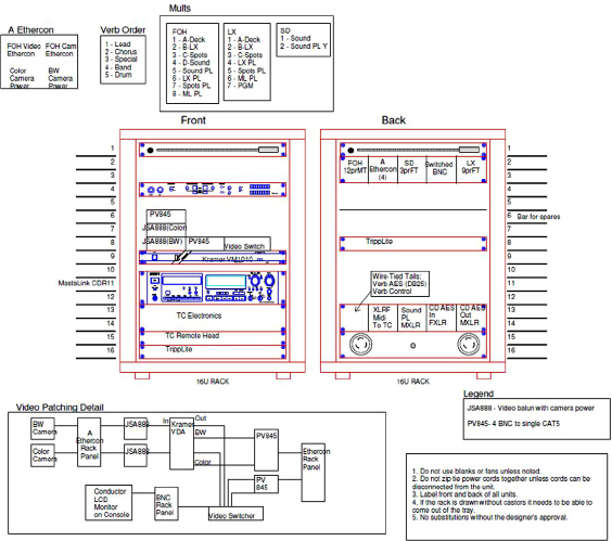
In Figure 9.1 we see a rack that is designed to go front of house at the mix position. This drawing shows the equipment that needs to live in this rack and where the design team wants the equipment to live in the rack. There are many times when you are building a show from a drawing where things need to shift once you start actually building the rack, but it is important to stay as accurate to the drawing as possible. As soon as you move something, you find out there was a specific reason that wasn’t clear to you about why it had been drawn that way. This drawing also includes the mult tails that need to go in the rack. We will discuss mults later in this chapter. It also gives a breakdown of the mult tails and of the patching scheme for the video components in the rack. Rarely do drawings include every answer to every question, but the rack drawings should offer enough answers that your build crew can put the rack together and patch it as needed.
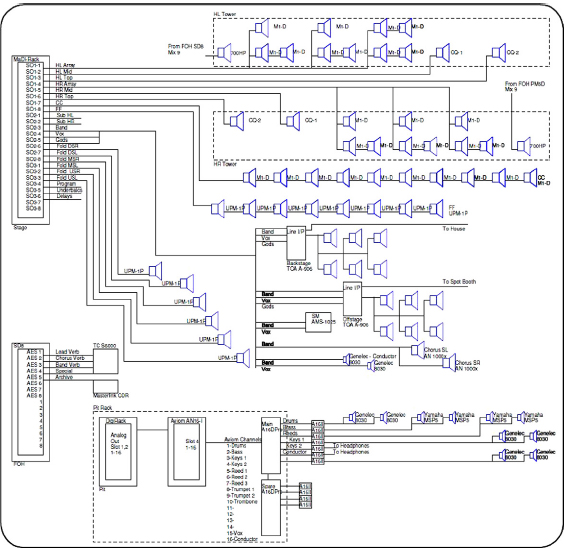
Figure 9.2. An output signal flow drawing.
Figure 9.2 is a typical signal flow drawing. This drawing focuses on the output section of the sound system. It gives you an overview of the speakers and amps in the system as well as any processing. It is a quick way to understand how A gets to B. It is not meant to answer every question about the sound system. If you try to add too much information on the signal flow drawings you will find the drawing growing out of control and hard to maintain. When working on a system it is important to know where to look for information and for that information to be provided in bite-size pieces. If you add too much information to your drawings, you can actually confuse people. For example, if you put the mult line number on your rack drawing for the House Left speaker and you put that on your signal flow and you create a label for it, then you run the risk of it changing and not updating it in all three places. That can confuse people trying to build the system. It is better to understand what people are looking for when they look at different pieces of paperwork. When looking at a signal flow drawing, people want a general overview. They want to quickly understand the components of the system and how they flow.
Figure 9.3 is a signal flow drawing for the midi. The midi flow can be fairly complex on a sound system. We use midi to trigger all kinds of devices. It is important to show how the midi system works, and this is a good place to show the midi channels that different devices are transmitting to or receiving from. Figure 9.4 is a signal flow drawing for the inputs. It very simply shows what is plugged into the different consoles on the show. It shows the name of the device and the model of the device.
It is very common for designers to do a signal flow drawing of the inputs and outputs and hand that drawing off to their assistant or associate or A1 and the rest of the drawings and paperwork are done by those people. It takes a lot of knowledge of the final product needed in order to take a signal flow drawing like that and transform it into a full-blown well-documented sound system, but once you know what you are doing, it is a good way to work. The first step in this process is to start doing rack drawings based on the flow drawings. You start putting the gear into racks and then you start to see the need for other equipment. Before you know it, you are trying to figure out how to cable the system.
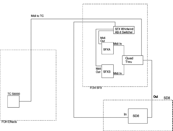
Figure 9.3. A midi signal flow drawing.
More than likely the designer did an equipment order that was given to the shop that was based on the signal flow and that is what the shop based their bid on. As you work on the rest of the paperwork you will start to make a list of the other equipment needed for the system. This includes cable and adaptors and racks and boxes. As you build this paperwork you will build a list of supplemental equipment that will need to be given to the shop. Once you arrive at the shop one of the first things you will want to do is get a list from the shop of what equipment they have put in their system for your order. You will want to compare that list with your list and make sure they match. This is a very important step because if their list doesn’t match then you could get to the end of the build and be missing some important piece of gear that is now back-ordered and not available. You also want to make sure the lists match so that as things change in the shop, you can give the shop an accurate list of changes to your order.
One reason why paperwork is so important is that the systems are so large that there are times when you need to be able to trace problems in the paperwork to figure out how to fix the problem. Another reason is because this may not be the last time you build the system. If you are lucky your show will be a big hit and it will go on tour and you will need to build it again for the tour. If the paperwork is accurate this is an easy process. If it isn’t then you end up making the same mistakes and digging yourself out of the same holes that you already worked your way out of the first time.
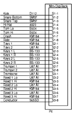
Figure 9.4. An input signal flow drawing.
In the shop, several pieces of paperwork are important. First is the order from the shop, which is the full list of everything you need to build the show. The order should be available for anyone to look at. Second are the checklists. It helps to have checklists that the build crew can use to keep track of what has been done. Figure 9.5 shows a typical checklist. The checklist shows you the name of the device and the model and it also shows you the location or box of the device and the color if it is to be color-coded. There is a box to mark when the item is done. Some checklists will also have a box for “Pulled” and “Labeled” so the item can be marked off as those things are completed.
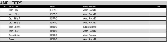
Figure 9.5. A typical checklist.
When I build a show I purchase file jackets, which are just like file folders except they are closed on the sides so it is more like a big envelope. I label the file jackets for the different parts of the system build such as “Microphones,” “Speakers,” and “Bundles.” I place the checklist and labels for each part in its respective file jacket. That way when the microphones are brought into our zone I can hand someone the “Microphones” file jacket and that person can go off and label all the mics and let me know if we received everything we were supposed to receive.
When I do my paperwork for a show I define which box or rack every device in the system goes in, and by doing that I can print a checklist and the appropriate labels for each box. I then create a file jacket for each rack and when I assign a person to build a rack I give him the file jacket. Once he has the file jacket he has the rack drawing and the checklist and the labels for the rack.
Labels are important. They are crucial. They are demanded. I have worked for a couple of designers who will look around the system after it has been loaded in and if they find a cable that isn’t labeled, they will unplug it. It is a good lesson to learn. The point is that your equipment should be labeled in such a way that you do not need any paperwork when you have your head buried in your doghouse, which is the term used for a box built around the back of a console to hide all the ugly connections. You should be able to pick up any cable and read what it is and where to plug it in. Without labels there would be chaos.
The labels for the system are usually done before you get to the shop and they are printed out in the first day of the build. For labels we typically use Avery labels sizes 8167 or 5167, and 8160 or 5160. The difference between the 81 and 51 is LaserJet versus InkJet. The 8160 label is called the mailing address label. The 8167 is called the return address label. Sometimes we use 8165, which are a full 8-1/2" × 11" size label. There are also generic versions of these labels that are identical.
Basically, with labels we are labeling two distinct things. We are labeling devices and connections. The word device was established for use in a sound system by the Sound Commission at USITT. A device is any item in your sound system. A microphone is a device and so are a speaker and a rack and an XLR barrel. We want to label every device in the system so that anyone looking at a device can read what it is. That means that we want a device label on the front and back of every piece of equipment, so that once you rack the gear, you will be able to see a label when you have your head in a rack looking at the back of a bunch of amps. When I print my device labels, I typically print three identical labels for each device so we have one label for the front, one for the back, and one for when you make a mistake. Device labels can be either large (8160) or small (8167) depending on the item. It is important for a device label to have the show name, the model number, and box or location of the device.
Figure 9.6a. A device label.

Figure 9.6b. A version of a cable label done by Kai Harada.
Figure 9.7. A connection label.
The other kind of label is for connections. Connection labels are always small 8167 size. Basically a sound system is made up of devices with connection points and we want to label them all. A connection label is similar to a device label but holds more information. As seen in Figure 9.7, in the upper left corner of the connection label we see the name of the connection’s parent device. In the upper right corner we see the name of the connection. This can be thought of as the signal for that connection. To the right of the label in the space in between the labels, we see the model number of the parent device. In the yellow section of the label below the name we see the patch information. This tells you exactly what the connection plugs into.
There are some rules that need to be followed when applying labels. These labels are paper labels with a gummy backing. The first thing we need to do is apply a piece of colored electrical tape or PVC tape to the device. Then the label is placed on top of the electrical tape. This makes it much easier for the shop to remove your labels when the gear is returned. If you put a paper label directly on a device then it will leave glue residue when you try to remove the label. It is important not to stretch the PVC tape as you apply it to the device. If the tape is stretched it will slowly recoil and pull itself off the device. The paper label is delicate and not made to last forever. The next thing we need to do is protect the label. We use transparent tape to completely cover the label and electrical tape. This gives the appearance of a laminated label. Be careful not to buy invisible tape. The name is deceiving because it is not invisible, it is cloudy. Transparent tape is completely see-through, but is more expensive.
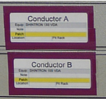
Figure 9.8. A device label properly attached to a piece of equipment.
Not all labels in your sound system will be printed paper labels like the ones above. Another important tool in the arsenal of the Broadway sound person is the Brother P-Touch. There are lots of times when you will need to P-Touch labels for devices and connections. The process is exactly the same as with the paper labels. Most commonly we use TZ-Tape for the P-Touch. The most common sizes are ½", ¾". There are times when you will need ¼" or 1" as well. Finally, the last line of defense in the battle to label your system is white gaff tape and a Sharpie. A few years ago Sharpie started making Twin-tip Sharpies, which gives you a normal Sharpie on one end and a fine-point Sharpie on the other end. These are the bomb.
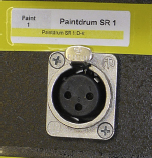
Figure 9.9. A connection label properly attached to a piece of equipment.
I have mentioned color coding a few times and I want to take a minute to expand on it. Every show on Broadway has a color coding scheme for the sound system. You color code things by using different colored electrical tape under the labels. You can also use different colored gaff tape when color coding large items such as cable crates and racks. The reason for color coding is to give some instant visual understanding to your sound system. The most important things to color code are your snakes and mults and XLRs. There are several different theories on color coding and it is usually up to the mixer to create a color code.
The most common system, and the one I use, is to give each snake a unique color for the box it is going to live in. An example is in the doghouse of my console. Let’s say I have three input snakes. I color code them patriotically as red, white, and blue. All the XLRs of snake A will be red. All the XLRs of snake B will be white. All the XLRs of snake C will be blue. This makes it easy for me to look in the doghouse and pick out the XLRs for a specific snake. Personally I have found this to be the best use of color in a sound system. There is also a system that all inputs are one color, all outputs are another color, and all intercom lines are a different color. I have also seen a system where interconnect cables out front are one color and stage runs are another color and pit runs are another color. It is a good idea to use color to help you. Whatever system you decide to use is fine, but just choose one and understand the goal and how easy it will be to color code your equipment using your system. I have seen some people try to color code different types of signal, which becomes a nightmare to build because you could have a snake with four different colors. That type of system will be very time consuming and complex for the people building your show.
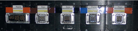
Figure 9.10. A rack color coded for multiple mults.
I have mentioned mults several times and now it is finally time to explain what a mult is. A common item in sound is a snake. A snake is a cable built with multiple conductors. One end of the cable usually has a breakout to several XLR tails and the other end has a breakout to an XLR box. Basically a mult is a snake that has a detachable box on one end and a detachable fan-out of XLR tails on the other end. The multicore cable that runs between the box and the tails is called a trunk. Mults come in a variety of sizes or pairs. Wireworks makes multichannel audio cables that are the standard for Broadway and these multichannel audio cables are usually called mults.
Walk backstage in any Broadway house and you will find MultiBoxes and MultiTails in almost every rack, and MultiTrunks will be no doubt dangling from above and plugged into the racks. The same holds true for most theatrical tours. Wireworks multicable or multicore is so integral to Broadway that Wireworks even created the Broadway Latching System, or BLS, to address the needs of the community. So how did it all start? How did this cable come about and how did it become an industry standard?
Gerald “Jerry” Krulewicz, president, and Larry Williams, chief operations officer, started Wireworks in 1974 because they saw a need for multicable. Jerry explains, “Our original markets were live theatre and broadcast. At the time there was no such thing as multicable. People used mic cable and taped it together with friction tape. It was a ridiculous situation. So we started a company. The cable was actually borrowed from the computer industry, which used shielded cable. We started with a stage box hard-wired to a fan-out on the other end. Back in the XLR days people would use small numbers of mics, but once multicabling came along, people wanted to put mics everywhere.”
When asked how Wireworks multicable was initially received he explains, “It was a product that was released at the right time to the right market. So it was like a miracle. It was a whole revelation. It made load-ins in New York quicker and helped immensely with touring. Some of the original designers started to name the different trunk cables and some of those standards have stuck. Between Otts (Munderloh) and Tony (Meola) they came up with a naming system which has gone on to become a standard. The industry not only adopted the multicabling idea, but the whole concept. This worked very well for the rental shops as well. It eliminated their need to have custom panels for every tour.”
“We first used homemade multicable or snakes on the West Coast in the late 60s. The remote recording trucks of the time, I believe, introduced snakes to the live sound world. I also remember bundling mic cables together to make our own sort of snake, but just for microphones. With multi-pin connectors and fan-outs, it became much simpler to build processing racks and it certainly became easier to run cable in mults wherever needed. Wireworks has been in the forefront of multicable design and fabrication and has been most helpful in assisting designers with new products that can serve many applications,” says Abe Jacob, sound designer of Jesus Christ Superstar and the original A Chorus Line among many others.
Tony Meola, sound designer of Wicked and Steel Pier among others, explains how he started using Wireworks multicable: “The first show I remember using multicable on was I Remember Mama designed by Otts Munderloh. I remember when I walked into Masque and there were six three pair mults on the order. They said you’ll get three XLRs taped together buddy and you’ll like it. Otts really pushed for multicable. When I told him they won’t give it to you, he said we’ll tell them they have to. Before multicable we bundled cables together. Back then the only multicable was more of a snake without breakouts. It was a box or tails at one end and tails at the other. It wasn’t easy to tour. And it was either 15 or 19 pairs. It was so long ago. I remember with Wireworks we would say can you make us a custom panel? And for every show we had custom panels. Eventually to keep the cost down I said we don’t need custom panels every time, we just need three, six, and nine pairs standard.”
Otts Munderloh, sound designer of Barnum and Dream Girls to name a couple, talks of his beginning with Wireworks multicable: “Multicable made it easier on the road. New York is an anomaly. You load in and everything changes. But it made it much easier on the road. I would have to say the tour of A Chorus Line was the first show to use multicable. In New York it was not multi. And that tour was ‘76–‘77. Jerry and Larry approached me to do my cables for A Chorus Line. I knew of Jerry. Jerry was the electrician on the bus and truck of Promises Promises the same year I was out on the bus and truck on I Do! I Do! and that was in ‘74. So I approached Abe and said do you want to use this? I was the mixer on A Chorus Line and I was mixing for Abe. That was in 1975. The shops were extremely resistant to buying multicable. One of the shops said to me, ‘If we buy this stuff then no one is ever going to use it again so we are going to charge the show for the price of the cable.’ And when I did my next show I said, ‘Where are my multicables?’ and they said they were all rented out. And that is how it started.”
For our purposes, we use mults to connect the sound system together. We use mults to send 19 XLRs from the RF Rack to the console. It is important for you to know the basic terminology for mults and the number of pairs available. Mults come in 3, 6, 9, 12, 15, or 19 pairs. A pair is actually the three wires needed for an XLR. Of course the mult tails could also be terminated for connectors other than XLRs. Mults have clips and ears that are used to plug the trunk into the tails. Mults can have a tail fan-out or the connectors could be built into a box that can be safely placed somewhere, or into a panel that can be built into a rack. MultTails can either be Stecked or Inline. Stecked means to attach the MultTail to a plate that allows you to mount the tailset in a rack using Steck Rails, such as a Middle Atlantic FK-2.
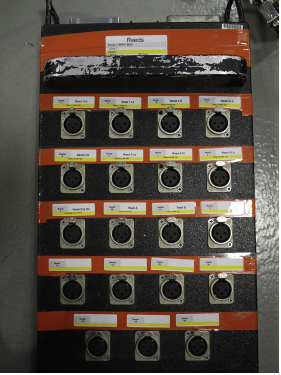
Figure 9.11. A MultBox that has been color-coded and labeled.
There are rules for labeling mults correctly and neatness counts. Figure 9.14 shows a 19pr that has been labeled correctly. To label a MultTail correctly it may be necessary to remove the clips so you can wrap the PVC tape completely around the connector. You also want to wrap the clear tape completely around. If you don’t get a full wrap with the clear tape, then the clear tape will peel off and the label will be destroyed. By looking at the label we can see that it is a Bundle label and the bundle is “Pit A,” which is printed vertically on the right. The box this bundle lives in is the “Pit Bundles” box, which is printed vertically on the left. The trunk name is “P.B” and the model is a “19pr 150”. The “From” line is highlighted and tells us which end of the cable we are looking at. The “To” line tells us where the other end of the cable is. A trunk has a male and a female end, but sometimes we write “M-(Pins)” and “F-(Holes)” so there is no confusion about what end is the male and the female.
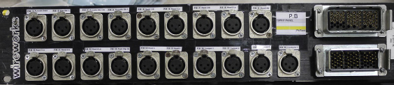
Figure 9.12. A MultPanel that has been color-coded and labeled.
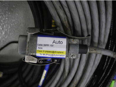
Figure 9.13. A 6-pair MultTrunk that has been color-coded and labeled.
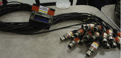
Figure 9.14. A 19-pair MultTail that has been color-coded and labeled.
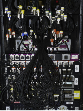
Figure 9.15. A typical Distro Rack filled with MultTails and MultPanels.
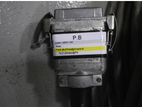
Figure 9.16. A labeled bundled trunk connector.
Figure 9.17 shows a labeled XLR. When labeling a connector it is a good idea to label it without restricting the ability to open the connector. If you find a problem with a connection you will want to open it to check the wiring. If the label has been done incorrectly you will need to remove the label in order to check the wiring.
Figure 9.18 shows a labeled MultBox. A common use for MultBoxes is as subsnakes in the pit. It is common to put a rack in a pit that has some 19pr panels that carry the mics to the console and from the pit rack you run mults to the different sections in the pit. This picture shows the MultBox that is a sub-snake for the Conductor. When labeling anything, you should think about how someone will hold the device to read it. You want the labels to be right-side up and read from left to right even when plugged in. It is also a good idea to make a decision on whether the labels on MultBoxes will be above the connection or below. Being inconsistent with that can get really confusing.
Figure 9.19 shows a labeled MultPanel. There is not a lot of room on MultPanels for labels so you do the best you can. MultPanels are also not always the same. Sometimes a 19pr panel is a 2-space panel with two rows of XLRs, and sometimes a 19pr panel is a 3-space panel with three rows of XLRs.
Figure 9.20 shows a labeled MultTrunk. This trunk was done incorrectly. There are several problems with the way this cable was labeled. Take a look at it and see if you can find the problems.
So here are the things done wrong with that label. The first thing you should notice is it is just messy. The person who did this label did not take the clips off the connector so the tape could be wrapped around. The PVC tape is hanging past where the connector seats, so there is no way this trunk will be able to be plugged in. The clear tape is not attached to anything on the right side. This label will pull off before you get it out of the box at load-in or it would pull off as you run the cable in the theatre and it gets pulled through some hole in the wall.
The way most shop preps begin is by labeling mults. This process can take a couple of days. Basically everyone sits around a table with colored electrical tape and clear tape and razor blades and screw drivers and sheets of labels and a checklist. We will use a 3-space metal blank and layout the colored electrical tape and cut the tape into small pieces with the razor blades. This process always starts a little slow as people get a system going, and then it ramps up. It is a good idea to take the time to do this part correctly and it is to be expected that someone will label an entire 19pr female tails before realizing he needed a 19pr male tails. That is where the spare labels come in handy. The challenge for the person who does the labels is that on day one all the labels need to be done for the connections in the show, which means basically that everything has already been thought out.
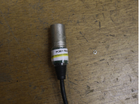
Figure 9.17. A labeled XLR connector.
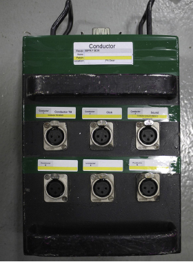
Figure 9.18. A labeled MultBox.
Another important term in building your show is bundles. A bundle is several cables that will be taped together using friction tape so they act as a single run (Figure 9.21). You bundle cables together that will run the same path. A bundle cuts down on the number of runs you have to pull at the load-in. For example, you will bundle three 19prs for the pit so you can save time at the load-in and only have one run to the pit for the 57 mic lines in the pit instead of three individual runs. There are places outside of New York that call a bundle a loom. While this may be an acceptable term where you come from, it is important to learn and use the terminology that is used in New York. If you persist in walking around the shop talking about your “looms,” you will probably have a hard time getting your bundles built.
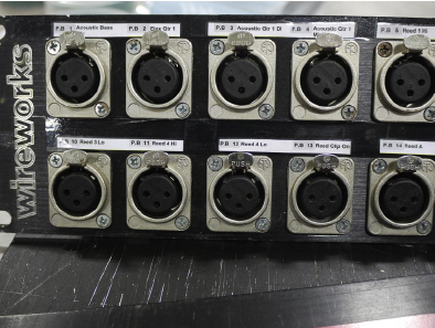
Figure 9.19. A labeled MultPanel.
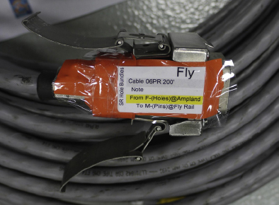
Figure 9.20. An incorrectly labeled MultTrunk.
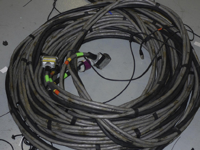
Figure 9.21. A bundle.
Before you arrived at the shop, hopefully you sent the shop your bundle information. That usually includes bundle sheets, a bundle summary, and possibly a list of the cables needed to build all the bundles. Figure 9.22 shows part of a bundle summary. A bundle summary shows all of the information about the bundles for the show. A bundle sheet is the exact same information as the bundle summary but it only has one bundle per page. The bundle information on the summary and sheet shows the cables that will be bundled together, the color e-tape for each cable, and where each cable is going from and to. A bundle summary is used as an overview to keep track of what has been done. The bundle sheets will stay with the cable. The normal order of a show build is to label mults first and while you are labeling mults, the shop pulls the bundled cable. Once you are done with the mult labels you move on to the bundles. It is a good idea to get the mults and bundles done first, because it takes a long time to get this stuff labeled and bundled.
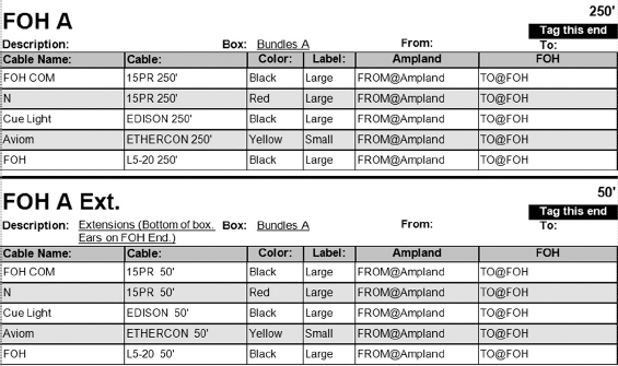
Figure 9.22a. A bundle summary.
Figure 9.22b. A bundle sheet done by Kai Harada.
The shop pulls the cable for your bundles. Sometimes the shop guys will lay the bundles out on the floor in a stack for each bundle. The bundle sheet will be placed on top of each stack. Then your build crew will label the bundles. As with everything, there are rules on how to label bundled cable. The rules on how to label a mult apply to bundled cables, but there are a couple of additional rules. A bundled cable has a different label for each end of the cable. If you look back at Figure 9.16 you will see how the “From” line is highlighted. That means this label is meant to go on the male end of the cable. The female end will look the same except the “To” row will be highlighted. When you label these cables it is necessary to tag one end of each cable to show which ends are to be on one end of the bundle. You are tagging one end so the guys in the shop can easily tell which ends group together.
Typically we tag the end with an obnoxiously colored gaff tape, such as green, pink, or orange. We use these colors because they are very obvious. It is also common to tag the “To” end. The “To” end is the end of the cable that will be pulled to a location. For example, if you are doing a pit bundle and the cable is going to run from the Pit to FOH (Front of House) and the box at load-in is going to be in the pit, then you would want the “To” end to be the FOH end because you are pulling the cable to FOH. If you tag these cables in a way so the gaff tape is permanent, then this tag can have a second use. When you open a box and see a bundle and you see the bright green tape on the ends, then you know that end pulls out of the box and to its destination. If you do not see the tape, then you know that the bundle was put in upside down and must be flipped over.
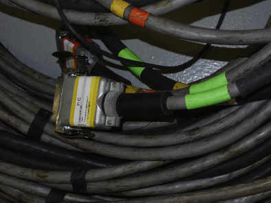
Figure 9.23. A bundle with the cables tagged for the “To” end.
When we talk about communications we are talking about Walkie-Talkies, intercom, and wireless intercom. We are talking about voodoo and the bane of our existence as sound people. We are talking about the most important and least important thing we have to do. It is the most important because without communications, or com, there can be no show, but it is also the least important because it has no effect on the quality of the sound of our show. Be that as it may, we are responsible for com and we have to learn everything we can about it and make sure it works flawlessly.
On Broadway we use many channels of com to keep conversations private when needed and public when necessary. The typical com system utilizes eight channels of com. The normal breakdown is Deck, Lighting, Spots, Sound, Lighting Private, Spots Private, Moving Lights Private, Sound Private. The stage manager gets the four “public” channels, which are Deck, Lighting, Spots, and Sound. This allows the stage manager to have communication with all the departments involved in running the show. The Deck channel consists of carpenters, flymen, props crew, and other stage managers. The Deck channel is also connected to the wireless com system. There are times when the wireless com system has two channels. In this case the people on wireless can have a private channel.
The conductor normally gets a single channel, which would be on the Sound channel. The sound crew has a public channel and a private channel. The sound crew may have several different places onstage for com. It is common for there to be several places for the sound crew to listen to the wireless mics and it is common to place a com beltpack at each of these positions. Mixers have different needs. Some mixers only want the Sound channel and the Sound Private channel, but others want all of the public channels at the mix position.
The lighting department is the most demanding when it comes to com. Usually each member of the lighting team gets a four-channel remote station with the com channels laid out like this: A-Lighting Public, B-Lighting Private, C-Spots Private, D-Moving Lights Private. Often the lighting people will call the Lighting Public channel the SM (or stage manager) channel. To them, the only reason they talk on that channel is to talk to the stage manager. The spot operators normally get a two-channel beltpack with the Spot Public and the Spot Private channels. There are times when one of the spot ops will call all of the spot cues. It is possible that only one spot op gets a two-channel beltpack and the other spot ops get a single-channel with just the Spot Public channel.
The reason the lighting channels are broken up this way is because different people need to have private conversations with different people at the same time. The lighting designer will mostly be talking to the moving light programmer and will occasionally talk to the stage manager. One of the assistant LDs will spend all of his/her time talking privately to the spots to explain what their cues are. Another assistant may be spending most of his/her time talking privately to the stage manager to make sure the cues are where they are supposed to be.
Recently projection design has become very popular in theatre. With the rise in the popularity of projection comes a need for more com channels. It may be necessary to add a Public and a Private channel for the projection team. Often the projection team will want the Lighting Private and Lighting Public channels as well. Lighting and projection have to work closely together so they are constantly talking with each other.
When planning a com system you will need to reach out to the other design teams to find out their needs. You also have to remember that your com system is temporary. It must be easy to set up in the house and easy to dismantle. It also needs to be easy to expand. You will be asked to add beltpacks for spot op subs to learn the show and for training stage managers and light board ops to learn the show. You will also be asked at some point to create a calling recording of the show, which is a recording of the show on the left channel and a recording of the stage manager calling the show on the right. In order to make this recording you can use a Clearcom DC Blocker, which is an inline XLR barrel, to strip the 38 volts off the com line and plug it into your recording device on the right channel. We are not allowed to make recordings of the show unless requested for training purposes.
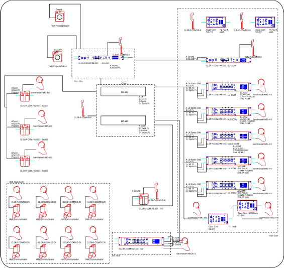
Figure 9.24. A Signal Flow ICOM drawing that represents a standard Broadway com system.
We are also responsible for the CCTV, or closed circuit TV, for the show. This video is not artistic and is not meant for the audience. This is video that is crucial to the running of the show. The most common camera needs are Conductor camera, FOH Black and White Low-light camera, FOH Color Camera. The Conductor camera is a shot of the conductor and is distributed to anyone who needs to follow the conductor. This shot will go to the mix position and the stage manager, as well as to a couple of video monitors on the balcony rail. The video monitors on the balcony rail will need to get their power from lighting and go through a blackout generator, which will allow lighting to cue these monitors on and off instantly. The conductor shot will also go to any location for offstage singing. The conductor shot may also be distributed throughout the pit. It is common to put a 5.6" LCD, or Delvcam, on top of most if not all music stands in the pit. The drummer and percussionist may require several conductor shots in their area.
The FOH Black and White Low-light camera allows the stage manager to see the stage with the lights up or down. We hang IR, or infrared, emitters that allow the cameras to see in the dark. This helps the stage manager call the show better, because he or she can see when things are placed in the dark. We also have an FOH Color camera because sometimes the black and white just isn’t high enough quality for the stage manager to call the show. These two cameras are normally hung on the balcony rail. Most of the cameras we use are typical CCTV cameras that are used in the security industry, but recently the FOH Color cameras being spec’ed are professional HD video cameras. The conductor camera is usually a small bullet or lipstick camera.
It is also possible for the show to need several other cameras. These are specialty cameras needed for stage management and automation to call the show. It is common to have an overhead camera on one of the electrics. It is also common to hang a camera that is able to be controlled remotely. Either the stage manager or the automation person will run the remote. These specialty shots can’t always be predicted. It is a good idea to leave room for expansion in your video system.
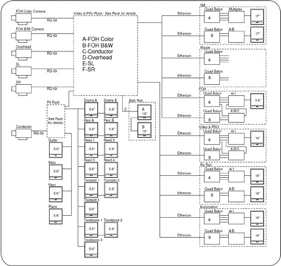
Figure 9.25. A signal flow video drawing that represents a standard Broadway video system.
Before we leave the shop, we put the entire sound system together and test it. This is a crucial part of having a smooth tech. I worked on one Broadway production that was an absolute mess. Not a single person on the design team had ever worked on Broadway and they had done very little planning for the build, and unfortunately the planning they had done was mostly wrong. Building that show was like pulling teeth. No one had an answer to any question. There were no bundle sheets. There were very few labels. The drawings were wrong. It took us three weeks in the shop to build the show and on the last day in the shop, we were still building bundles and labeling mult tails. The build was so messed up that nothing was tested in the shop. The result was a load-in that was painful. We would run a bundle out and find that one cable was backwards in the bundle. We would go to run in a speaker cable and find that cable was never ordered for that speaker. This had a snowball effect and led to a miserable tech. We were constantly behind. There was always something that didn’t work or wasn’t planned for. Even though this happens occasionally, it is not the norm and it is not the goal.
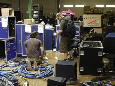
Figure 9.26. S cott Armstrong and Justin Stasiw setting up for testing.
As things progress with the system build, you will want to start planning for the testing period. You will want to plot out a space for the FOH and the Ampland. It is a good idea to have a drawing of what these areas will look like. Then you place the racks exactly the way they will be in the theatre. Then all the bundles and cables are patched in, and the system comes to life. It is the most exciting time in the shop. After weeks of planning and labeling you finally get to see what works and what doesn’t.
When we test the system we patch the entire system together before we start. This can make for a messy build zone because it takes so much cable to patch a system together. Usually we will start testing on either the video system or the com system. To test the video system we set up the cameras and hang a piece of paper in front of the camera that has the name of the camera shot written on it. That allows us to go to all the monitors in the system and verify the camera shots are correct. Next we test the com. This involves moving from com station to com station and making sure all channels work. The signal flow drawings come in very handy when testing the com and video systems. Those drawings make it easy to see if you have tested everything. When testing com, it is a good idea to first test the call light of each channel, then test the sound of each channel. There is nothing worse than hearing feedback from an unterminated clearcom channel. To avoid that, you can start with the call light. If the call light is not responding normally, then there is a problem and the channel will probably squeal if you turn it on.
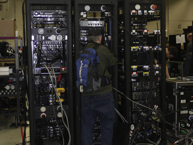
Figure 9.27. S cott Armstrong patching some backstage racks.
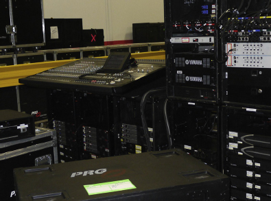
Figure 9.28. Ampland and the monitor desk setup for testing.
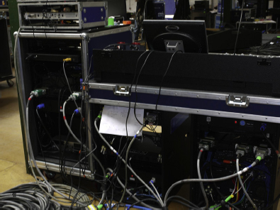
Figure 9.29. FOH setup for testing.
After we check the com and video we usually move on to testing the paging system. Testing the paging system includes testing the God mics, which are the mics used by the director and choreographer and the stage manager. Once this has been tested we are usually in a good place to dismantle parts of the system to be packed up. While that happens we test the inputs and outputs of the system. Part of testing the outputs includes listening to the speakers. The speakers we use are rental speakers, which means they could be at different places in their lifecycle. It is a good idea to listen to your speakers to make sure the components sound the same. Sometimes the shop will even test the speakers for you using Smaart or some other acoustical measuring program. Also we will test the speakers for polarity using a Cricket or a Minilyzer, to make sure the amps and speakers are wired correctly. To do this we send a popping sound to the speaker using one end of the Cricket and we use the microphone on the other end of the Cricket to make sure the popping coming out of the speaker is polarity correct. If you don’t test for polarity, you could end up in the theatre with speakers cancelling each other out and a very unhappy designer.
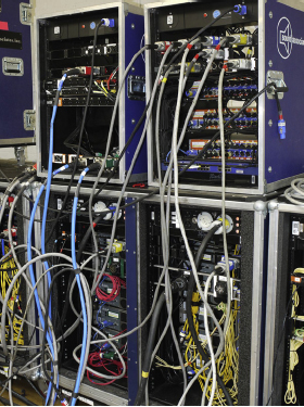
Figure 9.30. Racks patched for testing.
Once all of the testing is done, the only thing left to do is to pack up the system. All of the equipment needs to be safely packed so it can travel on a truck to the theatre. The process of packing a system can take days, which is why we start packing the video and com system as soon as possible. Before the testing is done, a lot of things can be packed up. The pit mics and stands can all be packed. The speaker yokes and spares can all be packed. Hopefully, a lot will be packed up before the testing is done.
When we pack a system, we tend to organize the system so it can be easily be found. We will pack all of the FOH (Front Of House) bundles in one or two boxes and label the boxes something like “Main Runs.” We try not to put “FOH” on a box unless the box itself is meant to be placed front of house, so in labeling the FOH runs we avoid the term “FOH.” We will box all of the pit runs in a couple of boxes and label them. We will pack things up that go to the same location in the theatre and we will label the box with the location the box needs to go at load-in. We also pack similar speakers together. Intercom will be its own box. Video monitors will take up several boxes.
We will pack a workbox with adaptors and video cameras and fragile equipment. We also pack similar cables together. There will usually be a box of NL4 and a box of power cables and a box of XLR. This doesn’t always work out perfectly. I did a load-in recently in which the pack was done in a strange way and it was challenging to find what you needed. In the end it was my fault for not watching how things were being packed more carefully. If that happens, you do the best you can to re-organize at the theatre.
Packing is important for several reasons. One is that this gear is rented and if it is damaged the production will have to pay for the damage, so when we pack we wrap delicate items in bubble-wrap and use foam to protect items from banging around. Part of packing involves understanding how things travel. Packing your system on a truck is like a living horizontal game of Tetris. One big difference is that if you get your pack wrong and have to redo it, you are going to endure a slew of ridicule from the Teamsters and stagehands who are loading the truck. When you pack a truck you need to know how wide your truck is and how many boxes will fit in to create a solid wall. You need to know what can stack and what can be flipped “wheels to the sky.” You need to know where to put load bars, which are solid bars that hook to the sides of the truck to create a stopping point so the gear can’t move. You also need to know where to put ratchet straps, which are like load bars but are thick straps instead of solid bars. The people loading the truck will take care of most of this, but it is a good idea to have a decent clue before you get near a truck.