
Low-Temperature, Hot Water Heating Systems
Expansion Facilities in Heating Systems
High-Temperature, Pressurised Hot Water Systems
Thermostatic Control of Heating Systems
Timed Control of Heating Systems
Radiators and convectors are the principal means of heat emission in most buildings. Less popular alternatives include exposed pipes and radiant panels for use in warehousing, workshops and factories, where appearance is not important. Embedded panels of pipework in the floor screed can also be used to create ‘invisible’ heating, but these have a slow thermal response as heat energy is absorbed by the floor structure.
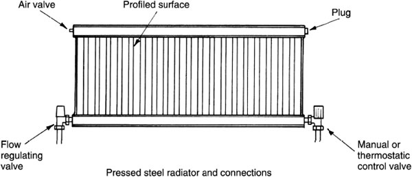
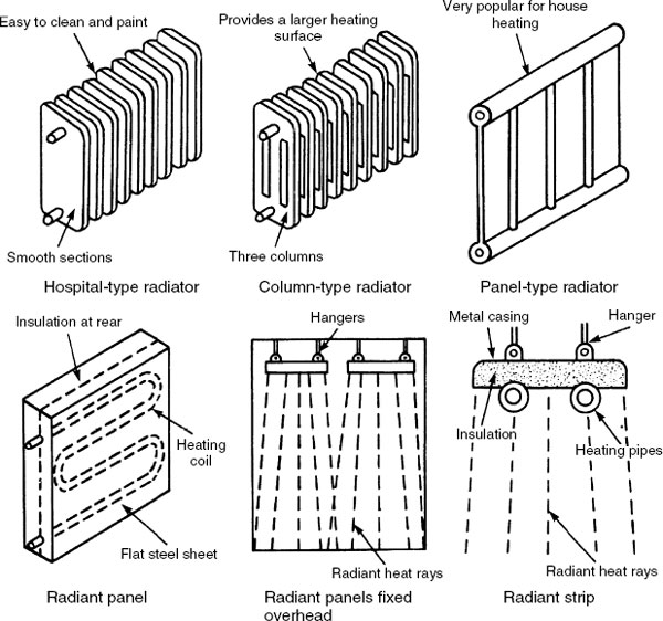
Despite the name, radiator, no more than 40% of the heat transferred is by radiation. The remainder is convected, with a small amount conducted through the radiator brackets into the wall. Originally, radiators were made from cast iron in three forms: hospital, column and panel. Hospital radiators were so called because of their smooth, easy-to-clean surface, an important specification in a hygienic environment. Column radiators vary in the number of columns. The greater the number, the greater the heat-emitting surface. Cast iron radiators are still produced to special order, but replicas in cast aluminium can be obtained. Cast iron panels have been superseded by pressed profiled steel-welded panels. These are much slimmer and easier to accommodate than cast iron in the modern house. In addition to the corrugated profile, finned backing will also increase the heating surface and contribute to a higher convected output. Pressed steel radiators are made in single, double and triple panels.
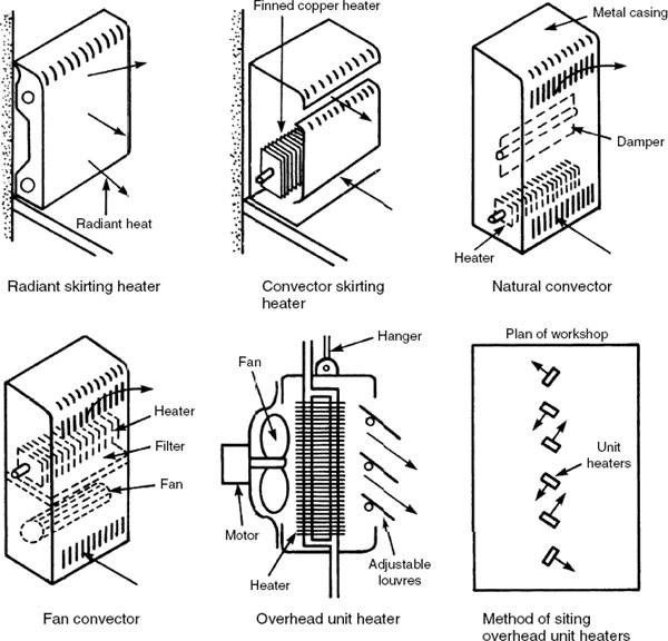
Convectors have a steel casing containing a finned heat exchanger. About 90% of the heat emission is convected and this may be enhanced if a thermostatically controlled fan is also located in the casing. They are more effective than radiators for heating large rooms, and in this situation their extra bulk can be accommodated.
In temperate and cold climates where there is insufficient warmth from the sun during parts of the year, heat losses from the human body must be balanced. These amount to the following approximate proportions: radiation 45%, convection 30% and evaporation 25%. Internal heat gains from machinery, lighting and people can contribute significantly, but heat emitters will provide the main contribution in most buildings.
Enhancement of radiator performance can be achieved by placing a sheet of reflective foil on the wall between the fixing brackets. Emitter location is traditionally below window openings, as in older buildings the draughts were warmed as they infiltrated the ill-fitting sashes. With quality double-glazed units this is no longer so important and in the absence of a window, locating a shelf above the radiator will prevent pattern staining of the wall due to convective currents. Radiant panels and strips suspend from the ceiling in industrial premises and other situations where wall space is unavailable.
Radiant and convector skirting heaters are unobtrusive at skirting level and provide uniform heat distribution throughout a room. Natural convectors have a heating element at a low level within the casing. This ensures that a contained column of warm air gains velocity before discharging to displace the cooler air in the room. Fan convectors may have the heater at high level with a variable speed fan located below. In summer, the fan may also be used to create air circulation. Overhead unit heaters are used in workshops to free the wall space for benches, machinery, etc. A variation may be used as a warm air curtain across doorways and shop entrances. Individual unit heaters may have a thermostatically controlled inlet valve, or a bank of several units may be controlled with zoning and diverter valves to regulate output in variable occupancy situations.
Low-temperature, Hot Water Heating Systems
In low-temperature, hot water heating systems the boiler water temperature is thermostatically controlled to about 80°C. Systems may be ‘open’ with a small feed and expansion cistern or mains fed ‘sealed’ with an expansion vessel.
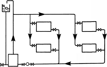
The type of system and pipe layout will depend on the building purpose and space available for pipework. A ring or loop circuit is used for single-storey buildings. Drop and ladder systems are used for buildings of several storeys. The drop system has the advantage of being self-venting and the radiators will not become airlocked. Traditional solid fuelled systems operate by convection or gravity circulation (otherwise known as thermo-siphonage). Contemporary practice is to install a pump for faster circulation and a more rapid and effective thermal response. This will also complement modern fuel controls on the boiler and allow for smaller pipe sizes. The additional running costs are minimal.
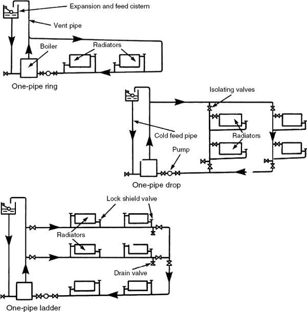
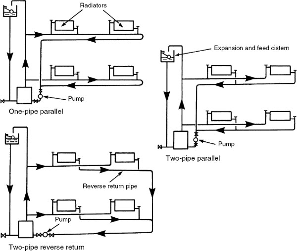
The one- and two-pipe parallel systems are useful where pipework can be accommodated within a floor structure, a raised floor or a suspended ceiling. The disadvantage with all one-pipe systems is the difficulty of supplying hot water to the radiators furthest from the boiler. As the heat is emitted from each radiator, cooling water returns to mix with the hot water supplying subsequent radiators, gradually lowering the temperature around the circuit. Eventually the last or ‘index’ radiator receives lukewarm water at best, necessitating a very large radiator to provide any effect. Pumped circulation may help, but it will require a relatively large-diameter pipe to retain sufficient hot water to reach the ‘index’ radiators. Two-pipe systems are less affected, as the cool water from each radiator returns directly to the boiler for reheating. However, radiators will need flow balancing or regulating to ensure an even distribution of hot water. The reverse-return or equal travel system requires the least regulating, as the length of pipework to and from each radiator at each floor level is equal. In all systems the circulating pump is normally fitted as close to the boiler as possible, either on the heating flow or return. Most pump manufacturers recommend location on the higher temperature flow.
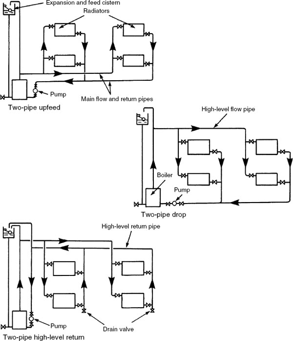
The two-pipe upfeed system is used when it is impractical to locate pipes horizontally at high level. The main heating distribution pipes can be placed in a floor duct or within a raised floor. The two-pipe drop is used where a high-level horizontal flow pipe can be positioned in a roof space or in a suspended ceiling, and a low-level return within a ground floor or basement ceiling. This system has the advantage of self-venting. The two-pipe high-level return system is particularly appropriate for installation in refurbishments to existing buildings with solid ground floors. In this situation it is usually too time consuming, impractical and possibly structurally damaging to cut a trough or duct in the concrete.
Low-temperature, Small Bore Hot Water Heating System
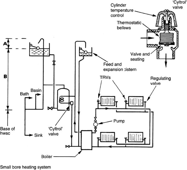
Pumped small bore heating systems have 28 or 22mm outside diameter copper tube for the main heating flow and return pipework, with 15mm o.d. branches to each radiator. This compares favourably with the old gravity/convection circulation systems which sometimes required pipes of over 50 mm diameter to effect circulation. If cylinder and boiler are separated vertically by floor levels, there will be sufficient pressure for hot water to circulate by convection through the primary flow and return pipes. However, most modern systems combine a pumped primary and heating flow with circulation regulated by thermostats and motorised valves. Variations in one- and two-pipe systems are shown on pages 141–143. Two-pipe systems are always preferred for more effective hot water distribution.
Notes:
- ‘Cyltrol’ valve to be as close as possible to hwsc, to sense hot water return temperature and maintain stored water at 60°C minimum. Where used with a solid fuel boiler, an unvalved radiator or towel rail is connected across the primary pipes to dissipate excess heat when the ‘cyltrol’ closes.
- Min. height of expansion pipe above cistern water level (A) = 1 B) in metres × 40mm + 150mm. E.g. if (B), cistern water level to base of hwsc is 2·5m, then (A) is 2·5 × 40mm + 150mm = 250mm.
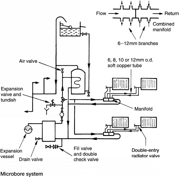
Low-temperature Microbore Hot Water Heating System
The microbore system also has pumped circulation through 28 or 22mm o.d. copper tube main flow and return pipes to radiators. The diameter depends on the number and rating of emitters connected. The difference between this system and conventional small bore is the application of a centrally located manifold between boiler and emitters. Manifolds are produced with standard tube connections for the flow and return and several branches of 6, 8, 10 or 12mm outside diameter. A combined manifold is also available. This is more compact, having a blank in the middle to separate flow from return. Manifolds are generally allocated at one per floor. Systems may be open vented or fitted with an expansion vessel. The advantage of microbore is ease and speed of installation, as long lengths of small-diameter soft copper tubing are produced in coils. It is also unobtrusive where exposed, very easily concealed and is less damaging to the structure when holes are required. Water circulation noise may be noticeable as velocity is greater than in small bore systems. Pumped circulation is essential due to the high resistance to water flow in the small diameter pipes.
Double-pump Heating and Hot Water Control
This is an alternative method for distributing hot water. It can be effected by using two separate pumps from the boiler flow: one to supply the hot water storage cylinder and the other the heating circuit. Grundfos Pumps Ltd have developed a purpose-made dual pump for this purpose, which is integrated into one body. This system conveniently replaces the conventional single pump and associated two- or three-port motorised distribution valves. Each pump is dedicated to hot water or heating and individually controlled by cylinder or room thermostat. The correct flow and pressure can be regulated to the characteristics of the specific circuit.

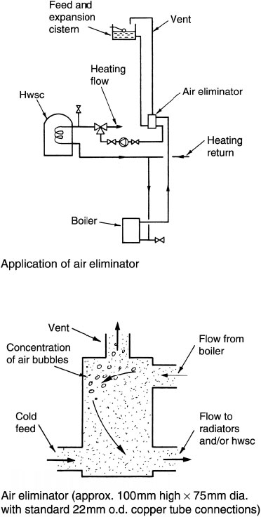
Air Elimination in Hot Water and Heating Systems
In conventional low-pressure systems, air and other gases produced by heating water should escape through the vent and expansion pipe. Air must be removed to prevent the possibility of airlocks, corrosion and noise. To assist air removal, a purpose-made device resembling a small canister may be used to concentrate the gases. This simple fitting is located on the boiler flow and vent pipe to contain the water velocity and ensure efficient concentration and release of air into the vent.
The system consists of 15mm or 22mm o.d. annealed copper pipes embedded in the floor, ceiling or walls. This has the benefit of avoiding unsightly pipes and radiators. Heat distribution is uniform, providing a high standard of thermal comfort as heat is emitted from the building fabric. However, thermal response is slow as the fabric takes time to heat up and to lose its heat. Thermostatic control is used to maintain the following surface temperatures:
Floors − 27°C
Ceilings − 49°C
Walls − 43°C
Joints on copper pipes must be made by capillary soldered fittings or by bronze welding. Unjointed purpose-made plastic pipes can also be used. Before embedding the pipes they should be hydraulically tested, as described on page 202.
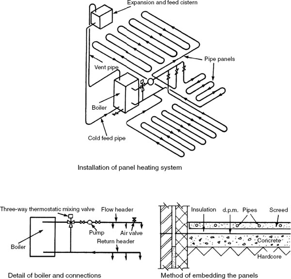
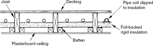
Current practice is to use jointless plastic piping in continuous coils. Pipes can be embedded in a 70mm cement and sand screed (50mm minimum cover to tube). In suspended timber floors the pipe may be elevated by clipping tracks or brackets with metallic reflective support trays, prior to fixing the chipboard decking. Materials include:
PEX: Cross-linked polyethylene.
PP: Co-polymer of polypropylene.
PB: Polybutylene.
These pipes are oxygen permeable; therefore, when specified for underfloor heating, they should include a diffusion barrier.
Alternative:
PEX/AL/PEX: Multi-layer pipe comprising cross-linked polyethylene with an aluminium core. Oxygen impermeable.
Boiler flow temperature for underfloor heating is about 50°C, while that for hot water storage and radiators is about 80°C. Therefore, where the same boiler supplies both hot water storage cylinder and/ or radiators and underfloor heating, a motorised thermostatic mixing valve is required to blend the boiler flow and underfloor heating return water to obtain the optimum flow temperature.
Extract from performance tables for a design room temperature of 21°C with a blended flow temperature of 50°C:
Solid floor – Pipe dia. (mm) |
Pipe spacing (mm) |
Output (W/m2) |
|---|---|---|
15 |
100 |
82 |
15 |
200 |
67 |
18 |
300* |
55 |
Suspended floor – 15 |
300* |
47 |
* Assumes two pipe runs between floor joists spaced at 600mm centres.
For a room with a solid floor area of 13·5m2 requiring a heating input of 779 watts (see page 189), the output required from the underfloor piping is:
![]()
Therefore, 15mm diameter pipe at 200mm spacing (67W/m2) is more than adequate, while 18mm diameter pipe at 300mm spacing (55W/m2) is just below.
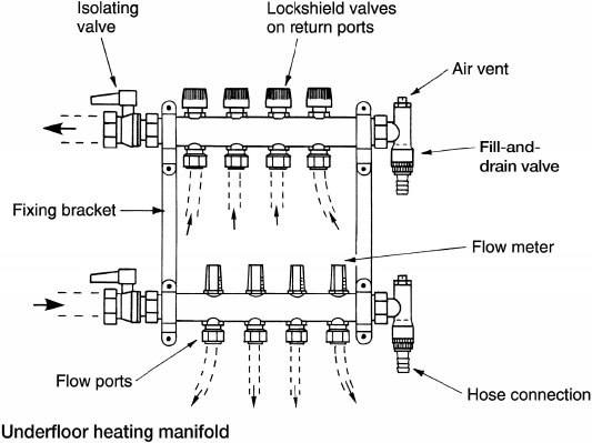
Manifold or header – manifolds are discretely located on a wall or within a boxed unit. Manifolds comprise:
Flow ports (2–12).
Return ports (2–12).
Drain valve and hose connection (may be used for filling).
Air ventilation valve.
Isolating valve to each bank of ports.
Visual flow meters to each flow port.
Lockshield balancing valve on each return port.
Installation notes –
One circulator per manifold.
Combined radiator and panel systems, one circulator for each system.
Screeded floor to have insulation turned up at edge to provide for expansion. Max. 40m2 or 8 m linear, without expansion joint.
Timber floor to have 6† 8 mm expansion gap around periphery.
Refs. BS 5955–8: Plastics pipework (thermoplastics materials).
BS 7291–1, 2 and 3: Thermoplastic pipes.
BS EN 1264–4: Water-based surface embedded heating and cooling systems. Installation.
Suspended timber floor – 1
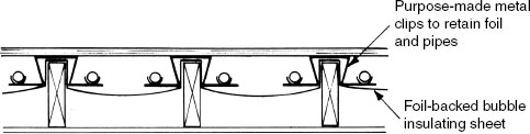
Suspended timber floor – 2
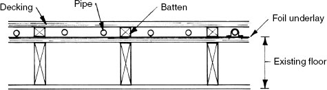
Suspended timber floor – 3 (existing floor structure not disturbed)
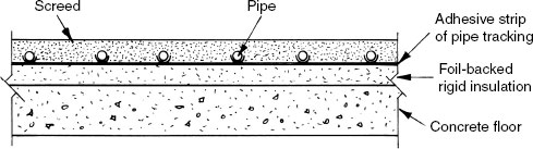
Solid floor – 1
Solid floor – 2
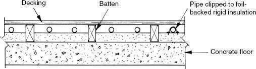
Note: In suspended timber floors 1 and 3, and solid floor 2, the void above and around the pipes can be filled with dry sand.
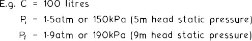
Schematic diagram of a solar energy panel in combination with a supplementary conventional boiler supply for hot water and underfloor heating –
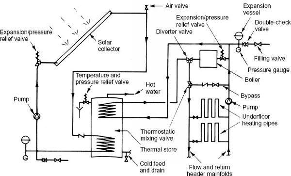
The storage cylinder has two primary heat exchange coils. The solar part of the system is connected to the lower coil and the boiler, and the heating circuit is connected to the upper coil.
For underfloor heating purposes, the thermostatic mixing valve maintains water at a constant delivery temperature by varying the proportions of hot flow water with cooler water returning via the bypass. A process known as modulating control.
Underfloor Heating – Heating Curve
The cost-effectiveness and efficiency of underfloor heating can be considerably improved when operating under steady-state modulated conditions regulated with a weather compensated circuit design (see pages 183 and 184). The system installation requires a motorised mixing valve and bypass, as shown on the previous page and on page 184. By computation of sensor-supplied data based on external temperature and the system heating curve, the control compensator regulates the flow temperature through the mixing valve.
Heating curve – a measure for comparing different system types, their
design and application. Criteria used are based on the relationship between water flow temperature, room temperature and external design temperature. For underfloor heating it is usual to select a flow temperature between 45°C and 55°C, with a return temperature of 35°C to 40°C. Typical heating curve values range between 0.85
and 1.50 for underfloor systems. Higher water temperature radiator systems have a value of about 2.50.
Formula –
![]()
Examples using an underfloor design flow temperature of 50°C compared with a radiator design flow of 80°C, both applied to an internal design temperature of 21°C and an external design temperature of –1°C:
Underfloor –
![]()
Radiators –
![]()
Expansion Facilities in Heating Systems
In any water-heating system, provision must be made for the expansion of water. A combined expansion and feed cistern is the traditional means. This will have normal expansion space under usual boiler-firing conditions of about 4% of the total volume of water in the system, plus a further third as additional expansion space for high boiler firing. Although the expansion can be accommodated up to the overflow level, there should be at least 25mm between overflow and the fully expanded water level.
Contemporary sealed systems have an expansion vessel connected close to the boiler. It contains a diaphragm and a volume of air or nitrogen to absorb the expansion. To conserve wear on the diaphragm, location is preferred on the cooler return pipe and on the negative side of the pump. System installation is simpler and quicker than with an expansion cistern. The air or nitrogen is pressurised to produce a minimum water pressure at the highest point on the heating system of 10kPa (approx. 1m head of water). In normal use, a pressure gauge with the expansion vessel will indicate about 1 bar (10 m head or 100 kPa).
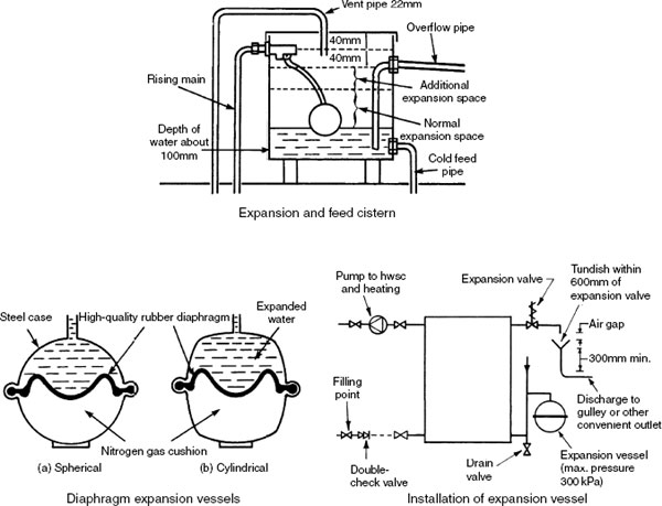
Expansion vessels are produced to BS 6144. They must be correctly sized to accommodate the expansion of heated water without the system safety/pressure relief valve operating. The capacity of an expansion vessel will depend on the static pressure (metres head from the top of the system to the expansion vessel), the system maximum working pressure (same setting as p.r.v.) obtained from the manufacturer’s details and the volume of water in the system (approx. 15 litres per kW of boiler power).
Capacity can be calculated from the following formula:
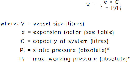
* absolute pressure is 1 atmosphere (atm) of approx. 100kPa, plus system pressure.
Water temp. = 80°C
Temp.°C |
Exp. factor |
|---|---|
50 |
0·0121 |
60 |
0·0171 |
70 |
0·0227 |
80 |
0·0290 |
90 |
0·0359 |
![]()
Ref. BS 6144, Specification for expansion vessels using an internal diaphragm, for unvented hot water supply systems.
Solar space heating must be complemented with a very high standard of thermal insulation to the building fabric. The solar panel shown on page 117 for hot water provision will need a much larger area, typically 40m2 for a three- to four- bedroom detached estate house. A solar tank heat exchanger of about 40m3 water capacity is located in the ground. It is fitted with a pre-set safety-type valve which opens to discharge water to waste if it should overheat. The solar panel and associated pipework are mains filled and supplemented with a glycol or antifreeze additive.
With diminishing fossil fuel resources and inevitable rising fuel prices, solar heating is encouraged as a supplement or even an alternative to conventionally fuelled systems. For use as the sole energy for a heating system there is still considerable scope for research and development. Technological developments are improving, particularly with the ‘heat bank’ or storage facility shown. In time it may become viable even with the UK’s limited solar energy in winter months.
See also page 121, Properties of Heat – Hot Water. The following additional data has particular application to the design of hot water heating systems and components.
CHANGE OF STATE. Water has three basic characteristic states: solid (ice), liquid (fluid) or gas (steam). Water changes state at the specific temperatures of 0°C and 100°C.
LATENT HEAT is the heat energy absorbed or released at the point of change from ice to water and from water to steam, i.e. where there is no change in temperature. This is measured as specific latent heat, in units of joules per kilogram (J/kg).
Specific latent heat of ice = 335kJ/kg
Specific latent heat of water = 2260kJ/kg
SENSIBLE HEAT is the heat energy absorbed or released during change in temperature.
E.g. to convert 1kg of ice at 0°C to steam at 100°C:
Ice at 0°C to water at 0°C = 1 kg × 335kJ/kg = 335kJ
Water at 0°C to water at 100°C = 1 kg × Shc of water (approx. 4.2kJ/kg K) ×100K = 420kJ
Water at 100°C to steam at 100°C = 1kg × 2260kJ/kg = 2260kJ
The total heat energy will be 335 + 420 + 2260 = 3015kJ
Note: Total heat is also known as enthalpy.
HEAT ENERGY TRANSFER can be by:
Conduction – heat travelling along or through a material without appreciable change in position of the material particles.
Convection – heat travelling by movement of particles as they expand or contract.
Radiation – heat transfer by electromagnetic waves through space from one material body to another.

High-temperature, Pressurised Hot Water Heating Systems
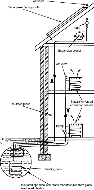
Pressurisation allows water to be heated up to 200°C without the water changing state and converting to steam. This permits the use of relatively small diameter pipes and heat emitters, but for safety reasons these systems are only suitable in commercial and industrial situations. Even then, convectors are the preferred emitter as there is less direct contact with the heating surface. Alternatively, radiators must be encased or provision made for overhead unit heaters and suspended radiant panels. All pipes and emitters must be specified to the highest standard.
Water can be pressurised by steam or nitrogen. Pressurised steam is contained in the upper part of the boiler. To prevent the possibility of the pressurised water from ‘flashing’ into steam, a mixing pipe is required between the heating flow and return. Nitrogen gas is contained in a pressure vessel separate from the boiler. It is more popular than steam as a pressurising medium, being easier to control, clean, less corrosive and less compatible with water. Air could be an alternative, but this is more corrosive than nitrogen and water soluble.
When pressurising with nitrogen it is important that the pressure increases in line with temperature. If it is allowed to deviate the water may ‘flash’ i.e. convert to steam, causing system malfunction and possible damage to equipment.
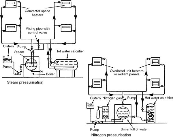
To commission the system:
Water is pumped from the feed and spill cistern.
Air is bled from high levels and emitters.
Air is bled from the pressure vessel until the water level is at one-third capacity.
Nitrogen is charged into the pressure vessel at half-design working pressure.
Boiler-fired and expansion of hot water causes the water volume and nitrogen pressure in the vessel to double.
Note: Pressure vessel must be carefully designed to accommodate expanded water – approximately 4% of its original volume.
Safety features include a pressure control relay. This opens a motorised valve which lets excess water spill into the feed cistern if the boiler malfunctions and overheats. It also detects low pressure, possibly from system leakage, and engages the feed pump to replenish the water and pressure.
Steam was the energy source of the Victorian era. At this time electricity and associated equipment that we now take for granted were in the early stages of development. Steam was generated in solid fuel boilers to power engines, drive machines and for a variety of other applications, not least as a medium for heat emitters. In this latter capacity it functioned well, travelling over long distances at high velocity (24–36m/s) without the need for a pump.
By contemporary standards it is uneconomic to produce steam solely for heating purposes. However, it can be used for heating where steam is available from other processes. These include laundering, sterilising, kitchen work, manufacturing and electricity generation. Most of these applications require very high pressure; therefore pressure-reducing valves will be installed to regulate supply to heating circuits.
Steam systems maximise the latent heat properties of water when evaporating. This is approximately 2260kJ/kg at boiling point, considerably more than the sensible heat property of water at this temperature of approximately 420kJ/kg. Because of this high heat property, the size of heat emitters and associated pipework can be considerably less than that used for hot water systems.
Steam terminology:
Absolute pressure − gauge pressure + atmospheric pressure (101.325kN/m2 or kPa).
Latent heat – heat which produces a change of state without a change in temperature, i.e. heat which converts water to steam.
Sensible heat – heat which increases the temperature of a substance without changing its state.
Enthalpy – total heat of steam expressed as the sum of latent heat and sensible heat.
Dry steam – steam which has been completely evaporated, contains no droplets of liquid water.
Wet steam – steam with water droplets in suspension, present in the steam space, typically in pipes and emitters.
Flash steam – condensate re-evaporating into steam after passing through steam traps.
Saturated steam – steam associated with or in contact with the water in the boiler or steam drum over the boiler.
Superheated steam – steam which is reheated or has further heat added after it leaves the boiler.
– |
low pressure, 35kPa-1 70kPa (108–1 30°C). medium pressure, 170kPa-550kPa (130–1 60°C). high pressure, over 550kPa (160°C and above). Note: Gauge pressures shown. |
Systems can be categorised as gravity or mechanical. In both, the steam flows naturally from boiler to emitters without the need for a pump. In the mechanical system a positive displacement pump is used to lift condensed steam (condensate) into the boiler. Steam pressure should be as low as possible as this will increase the latent heat capacity. A steam trap prevents energy loss at each emitter. These are fitted with a strainer or filter to contain debris and will require regular cleaning. A sight glass after each trap gives visual indication that the trap is functioning correctly, i.e. only condensate is passing. On long pipe runs a ‘drip relay’ containing steam valve, strainer, trap, sight glass and a gate valve will be required to control condensing steam. This is represented by the strainer and trap in the mechanical system shown below. Expansion loops or bellows will also be required on long pipe runs to absorb thermal movement. All pipework and accessories must be insulated to a very high standard.
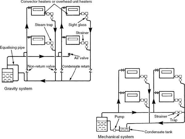
The purpose of a steam trap is to separate steam from condensate, retaining the energy-efficient steam in distribution pipework and emitters. Traps are produced in various forms and sizes to suit all situations, some of which are shown below. The thermostatic and bi-metallic types are for relatively small applications such as radiators and unit heaters. The bucket and ball-float types are more suited to separating larger volumes of condensate and steam at the end of long pipe runs and in calorifiers.
Thermostatic – bellows expand or contract in response to steam or condensate respectively. Lower temperature condensate passes through.
Bi-metallic – condensate flows through the trap until higher temperature steam bends the strip to close the valve.
Bucket – condensate sinks the bucket. This opens the valve, allowing steam pressure to force water out until the valve closes.
Ball-float – the copper ball rises in the presence of condensate opening the valve to discharge water until steam pressure closes the valve.

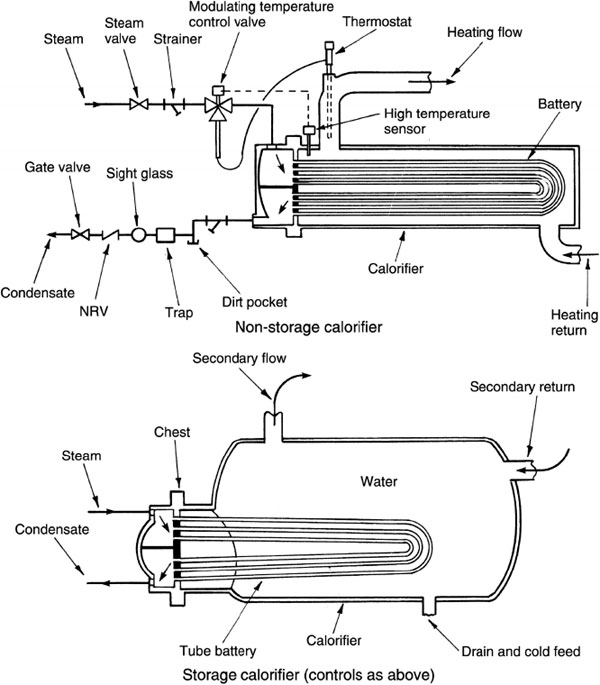
Non-storage type – used for providing instantaneous hot water for space heating. The steam tube bundle or battery occupies a relatively large area compared to the surrounding amount of water. To avoid temperature override and to control the steam flow, a thermostat and modulating valve must be fitted.
Storage type – used to store hot water for manufacturing processes and/or washing demands. Unlike non-storage calorifiers, these have a low steam-to-water ratio, i.e. a relatively small battery of steam pipes surrounded by a large volume of water.
High-level fan-assisted unit heaters are often the preferred means of heat emission for use with steam heating systems. Unless housed, radiators and convectors can be dangerously hot to touch, and they take up useful floor space in industrial production and warehouse premises. A typical installation is shown below with a non-return type of check valve to control the flow of condensate.

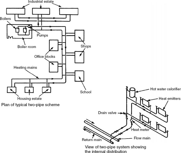
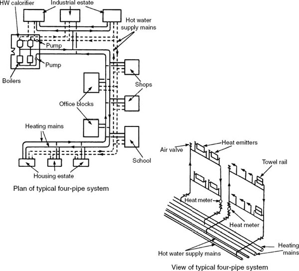
A district heating system is in principle an enlarged system of heating one building, extended to heat several buildings. It can be sufficiently large to heat a whole community or even a small town from one centralised boiler plant. Centralising plant and controls saves space in individual buildings. An effective plant management service will ensure the equipment is functioning to peak efficiency. Each building owner is required to pay a standing charge for the maintenance of plant and to subscribe for heat consumed through an energy metered supply, similar to other utilities. An energy meter differs from a capacity or volume meter by monitoring the heat energy in the water flow, as this will vary in temperature depending on the location of buildings. The boiler and associated plant should be located in close proximity to buildings requiring a high heat load, e.g. an industrial estate. Long runs of heating pipes are required and these must be well insulated. They are normally located below ground but may be elevated around factories. Systems can incorporate industrial waste incinerators operating in parallel with conventional boilers and may also use surplus hot water from turbine cooling processes in power-stations or electricity generators. This is known as Combined Heat and Power.
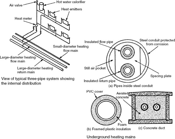
The three-pipe system is similar to the two-pipe system except for an additional small-diameter flow pipe connected to the boilers. This is laid alongside the larger diameter flow pipe and has a separate circulation pump. This smaller flow pipe is used during the summer months when space heating is not required, although in the intermediate seasons it could supply both with limited application to heating. It should have enough capacity to supply the heating coils in the hot water storage cylinders plus a small reserve. It can be seen as an economy measure to reduce hot water heating volume, energy loss from the larger diameter pipe and pump running costs. A common large-diameter return pipe can be used.
Pipes must be at least 450mm below the surface as protection from vehicle loads. They must also be well insulated against heat loss and frost damage if water is not circulating. Insulation must be waterproof and the pipes protected from corrosion. Inevitably there will be some heat losses from the mains pipework. This will approximate to 15% of the system heating load.
The four-pipe system supplies both hot water and space heating as two separate systems. Individual hot water storage cylinders are not required, as large-capacity calorifiers are located in the boiler plant room and possibly at strategic locations around the district being served. This considerably simplifies the plumbing in each building as cold water storage cisterns are also unnecessary, provided all cold water outlets can be supplied direct from the main. However, the boiler plant room will be considerably larger to accommodate the additional components and controls. Excavation and installation costs will also be relatively expensive, but system flexibility and closure of the heating mains and associated boilers during the summer months should provide economies in use.
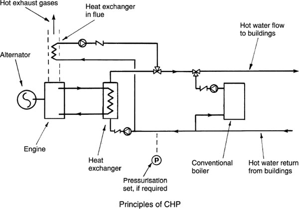
Potential for more economic use of electricity-generating plant can be appreciated by observing the energy waste in the large plumes of condensing water above power-station cooling towers. Most powerstations are only about 50% efficient, leaving a considerable margin for reprocessing the surplus hot water.
Combining electricity generation with a supply of hot water (cogeneration) has become viable since the deregulation and privatisation of electricity supply. Prior to this, examples were limited to large factory complexes and remote buildings (e.g. prisons), which were independent of national power generation by special licence. Until recently, CHP has only been practical for large buildings or expansive collections of buildings such as university campuses and hospitals.
Development of gas-fuelled micro-CHP for use in domestic situations is now viable, using units that are essentially a condensing boiler with an electricity generator. See page 677.
Surplus energy from oil- or gas-fired engine-driven alternators occurs in hot water from the engine cooling system and the hot exhaust gases. In a CHP system the rate of heat energy produced is directly related to the amount of electricity generated. There will be times when available hot water is insufficient. Therefore a supplementary energy source from a conventional boiler will be required.
All pipe materials expand and contract when subject to temperature change. This linear change must be accommodated to prevent fatigue in the pipework, movement noise, dislocation of supports and damage to the adjacent structure.
Expansion devices:
Natural changes in direction.
Axial expansion bellows.
Expansion loops.
Bellows and loops are not normally associated with domestic installations.
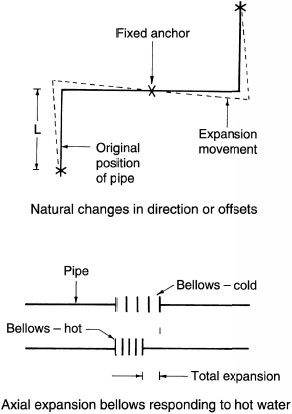
Bellows are factory-made fittings normally installed ‘cold-drawn)’ to the total calculated expansion for hot water and steam services. The bellows can then absorb all anticipated movement by contraction. Where the pipe content is cold or refrigerated fluids, the bellows are compressed during installation.

Coefficients of linear expansion for common pipework materials:
Material |
Coeff. of expansion (m/mK × 10–6) |
|---|---|
Cast iron |
10·22 |
Copper |
16·92 |
Mild steel |
11·34 |
PVC (normal impact) |
55·10 |
PVC (high impact) |
75·10 |
Polyethylene (low density) |
225·00 |
Polyethylene (high density) |
140·20 |
ABS (acrylonitrile butadiene styrene) |
110·20 |
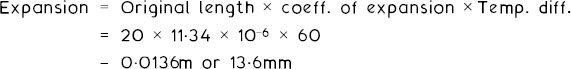
E.g. An 80mm-diameter steel pipe of 20m fixed length is subject to a temperature increase from 20°C to 80°C (60K).
Formula:
Single offset:
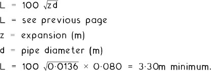
Loops:
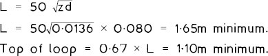
Top of loop = 0·67 × L = 1·10m minimum.
Notes:
Provide access troughs or ducts for pipes in screeds (Part 15).
Sleeve pipework through holes in walls, floors and ceilings (see page 434 for fire sealing).
Pipework support between fixed anchors to permit movement, i.e. loose fit brackets and rollers.
Place felt or similar pads between pipework and notched joists.
Branches to fixtures to be sufficient length and unconstrained to prevent dislocation of connections.
Allow adequate space between pipework and structure.
Thermostatic Control of Heating Systems
Thermostatic control of heating and hot water systems reduces consumers’ fuel bills, regulates the thermal comfort of building occupants and improves the efficiency of heat-producing appliances.
Approved Document L to the Building Regulations effects these provisions. This has the additional objective of limiting noxious fuel gases in the atmosphere and conserving finite natural fuel resources.
A room thermostat should be sited away from draughts, direct sunlight and heat emitters, at between 1·2 and 1·5m above floor level. Thermostatic radiator valves may also be fitted to each emitter to provide independent control in each room. A less expensive means of controlling the temperature in different areas is by use of thermostatically activated zone valves to regulate the temperature of individual circuits.
Three-port thermostatic valves may be either mixing or diverting. The mixing valve has two inlets and one outlet. The diverting valve has one inlet and two outlets. Selection will depend on the design criteria, as shown in the illustrations.
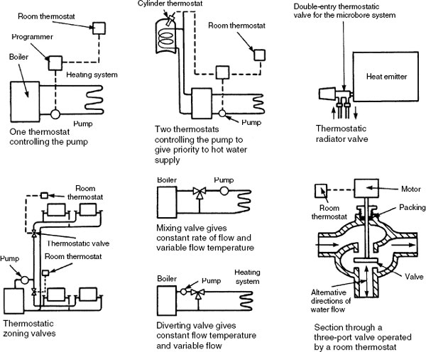
Thermostatic and Timed Control of Heating Systems
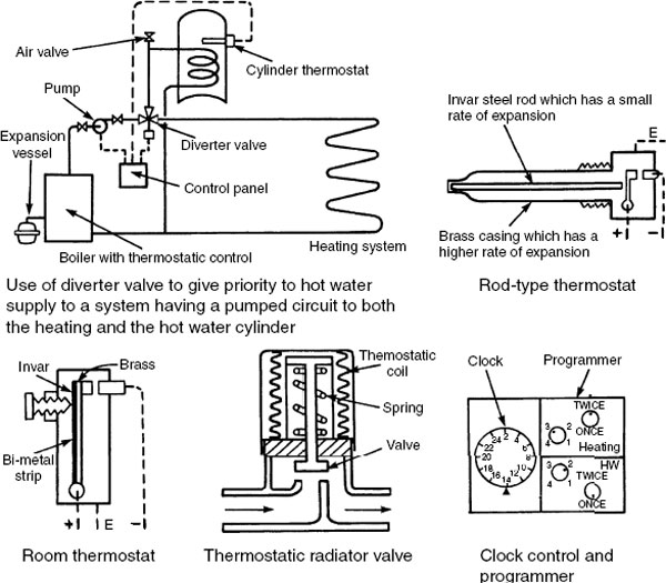
The diverter valve may be used to close the heating circuit to direct hot water from the boiler to the hot water cylinder. The reverse is also possible, depending on whether hot water or heating is considered a priority. With either, when the thermostat on the priority circuit is satisfied it effects a change in the motorised diverter valve to direct hot water to the other circuit.
A rod-type thermostat may be fitted into the hot water storage cylinder, or a surface contact thermostat applied below the insulation. At the pre-set temperature (about 600C) a brass and invar steel strip expands to break contact with the electricity supply. A room thermostat also operates on the principle of differential expansion of brass and invar steel. Thermostatic radiator valves have a sensitive element which expands in response to a rise in air temperature to close the valve at a pre-set temperature, normally in range settings 5–27°C. Sensors are either a thermostatic coil, or a wax or liquid charged compartment which is insulated from the valve body.
A clock controller sets the time at which the heating and hot water supply will operate. Programmers are generally more sophisticated, possibly incorporating seven- or 28-day settings, bypass facilities and numerous on/off functions throughout the days.
Heating Systems, Further Regulations and Controls
Ref. Building Regulations, Approved Document L1: Conservation of fuel and power in dwellings –
From 2002 it has been mandatory in the UK to provide a higher standard of controls for hot water and heating installations. This is to limit consumption of finite fuel resources and to reduce the emission of atmospheric pollutants. All new installations and existing systems undergoing replacement components are affected.
Requirements for ‘wet’ systems –
Only boilers of a minimum efficiency can be installed. See SEDBUK values on page 129 and 131.
Hot water storage cylinders must be to a minimum acceptable standard, i.e. BSs 1566 and 3198: Copper indirect cylinders and hot water storage combination units for domestic purposes, respectively for vented systems. BS EN 12897: Water supply. Specification for indirectly heated unvented (closed) storage water heaters. Vessels for unvented systems may also be approved by the BBA, the WRC or other accredited European standards authority. See pages 688 and 689.
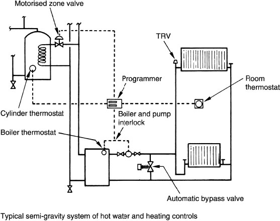
New and replacement systems to be fully pumped. If it is impractical to convert an existing gravity (convection) hot water circulation system, the heating system must still be pumped, i.e. it becomes a semi-gravity system (see pages 171 and 175). Where a new boiler is installed, a fully pumped system is required. Existing system controls to be upgraded to include a cylinder thermostat and zone (motorised) valve to control the hot water circuit temperature and to provide a boiler interlock. Other controls are a programmer or clock controller, a room thermostat and thermostatic radiator valves (TRVs to BS EN 215) on all radiators except in rooms with a thermostat and in bathrooms.
Note: The boiler is said to be ‘interlocked’ when switched on or off by the room or cylinder thermostat (or boiler energy management system). The wiring circuit to and within the boiler and to the pump must ensure that both are switched off when there is no demand from the hot water or heating system, i.e. the boiler must not fire unnecessarily even though its working thermostat detects the water content temperature to be below its setting.
Independent/separate time controls for hot water and space heating. The exceptions are:
combination boilers which produce instantaneous hot water, and
solid fuel systems.
Boiler interlock to be included to prevent the boiler from firing when no demand for hot water or heating exists.
Automatic bypass valve to be fitted where the boiler manufacturer specifies a bypass circuit.
Note: A circuit bypass and automatic control valve is specified by some boiler manufacturers to ensure a minimum flow rate while the boiler is firing. This is particularly useful where TRVs are used, as when these begin to close, a bypass valve opens to maintain a steady flow of water through the boiler. An uncontrolled open bypass or manually set bypass valve is not acceptable as this would allow the boiler to operate at a higher temperature, with less efficient use of fuel.
Independent temperature control in living and sleeping areas (TRVs could be used for bedroom radiators).
Installations to be inspected and commissioned to ensure efficient use by the local authority Building Control Department or self-certified by a ‘competent person’ i.e. Gas Safe Registered, OFTEC or HETAS approved (see page 130).
System owners/users to be provided with equipment operating guides and maintenance instructions. This ‘log-book’ must be completed by a ‘competent person’.
Dwellings with less than 150m2 living space/floor area to have two space heating zones with independent temperature control, one dedicated to the general living area.
Dwellings with over 150m2 living space/floor area to have the heating circuits divided into at least two zones. Each to have independent time and temperature control and to be included in the boiler interlock arrangement. A separate control system is also required for the hot water.
Requiremets for ‘dry’ systems –
Warm air or dry systems (see page 186) should also benefit fully from central heating controls. Although gas-fired air heaters are not covered by SEDBUK requirements, these units should satisfy the following standards:
BS EN 778: Domestic gas-fired forced convection air heaters for space heating not exceeding a net heat input of 70kW, without a fan to assist transportation of combustion air and/or combustion products, or
BS EN 1319: Domestic gas-fired forced convection air heaters for space heating, with fan-assisted burners not exceeding a net heat input of 70kW.
Replacement warm air heat exchanger units can only be fitted by a ‘competent person’. All newly installed ducting should be fully insulated.
Note: Boiler and pump interlock is the wiring configuration as explained on the previous two pages.
Schematic of control systems –
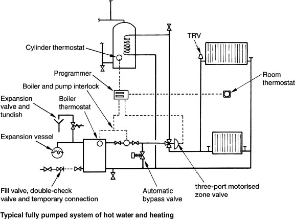
Note: Boiler and pump interlock is the wiring configuration as explained on pages 173 and 174.
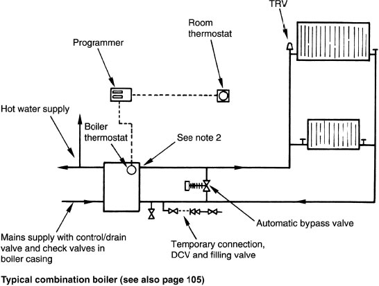
Notes: 1. Hot water draw-off taps supplied direct from mains, through instantaneous water heater. 2. Heating water is sealed. Additional components include heating pump and expansion vessel in boiler casing, with expansion valve and tundish (see upper diagram).
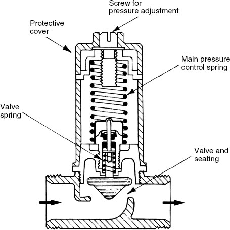
Modern boilers and heating systems are low water content to provide fuel efficiency and a rapid response. Therefore, to maintain a minimum flow through the boiler and to accommodate pump overrun, most boiler manufacturers will specify that a system bypass be used with their products.
An open bypass or bypass with a valve set in a fixed open position will satisfy the basic objectives, but with the boiler flow pipe feeding the return pipe at all operating times, the boiler will need to function at a higher temperature than necessary to fulfil system requirements. In addition, the heat energy transferred into the system will be limited, as a proportion of boiler flow water will be continually diverted through the bypass pipe.
Thermostatically controlled radiator valves and motorised zone and circuit valves are now standard installation. With these controls parts of the system may be closed, leaving only a limited demand for heat. Selective demands will cause varying pump pressures, unless a bypass valve is in place to automatically adjust, regulate and respond to pressure changes from the pump. Some applications are shown on the previous two pages.
Typical automatic bypass valve –
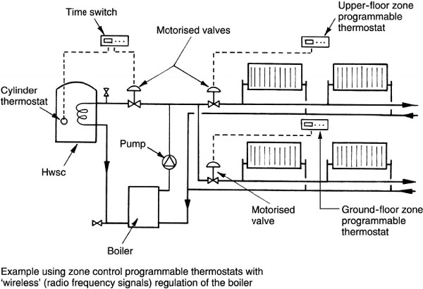
Programmable Thermostatic Zone Control
In addition to high-efficiency boilers, optimiser controls, thermostatic radiator valves and other fuel-saving measures considered elsewhere in this chapter, further economies and user comforts can be achieved by installing programmable thermostats with motorised valves dedicated to heat only a specific part or zone within a building.
Zone control or zoning provides fuel saving and user convenience by regulating heat/energy distribution to particular locations in response to occupancy. This prevents wasteful distribution of heat in a building that is not fully utilised.
Examples where zoning has greatest benefit:
Unused upper-floor rooms, i.e. bedrooms, during daytime.
Supplementary accommodation, bedsit or granny flat.
Conservatories or other rooms with heating characteristics which are weather and seasonally variable.
Office in the home, occupied while the remainder of the house is not.
People with irregular working patterns (e.g. shift workers) may require heating downstairs when others will not.
Insomniacs and people who get up regularly in the night (the elderly?) may require heating in a specific room at unusual times.
Note: See page 154 for boiler feed/fill and expansion facilities.
Time Proportional and Integral Programmable Control
Time proportional and integral (TPI) control matches boiler firing to system load demand. Boiler output is regulated proportionally with the temperature difference between varying room air temperature and the required set design temperature.
Standard room thermostats are effectively temperature-controlled switches, whereas TPIs incorporate programmable software. This provides accurate temperature control with minimal boiler firing, thereby maximising fuel use efficiency.
Graphical comparison between traditional on-off thermostat system operation with TPI programmable control –
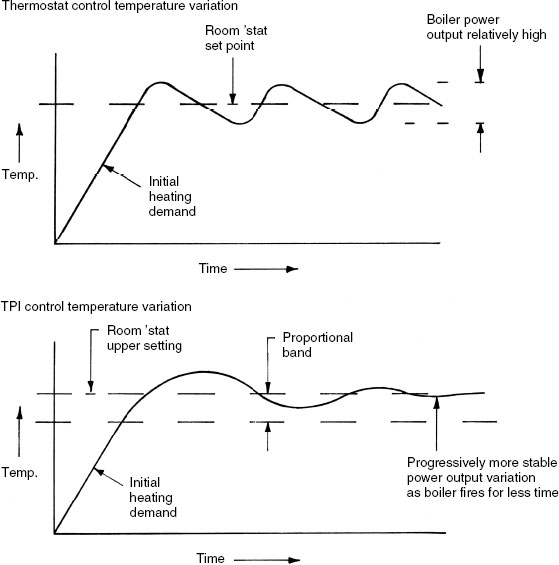
TPI operating principle – when room air temperature reaches the lower part of the proportional band, the TPI thermostat reduces the boiler firing time relative to heating demand (e.g. a proportional band set between 20°C and 22°C). When room temperature is at 21°C (i.e. half-way across the band), the boiler fires proportionally for half of the cycle period. Likewise, as room temperature increases above 21°C the boiler will fire proportionally less. Control temperature will be smooth as shown in the graph, varying little relative to system performance with a traditional on-off thermostat. TPI complements boiler interlock requirements (see pages 173–174), optimising boiler firing time.
Piped water systems in modern, highly insulated buildings are unlikely to be affected by modest subzero external temperatures. Nevertheless, an automatic 24-hour frost damage fail-safe facility may be specified as a client requirement or to satisfy an insurer’s standards. This is particularly appropriate for buildings located in very exposed parts of the country, and for buildings that are periodically unoccupied.
Frost thermostat – similar in appearance to a normal room thermostat but with a lower temperature range. Installed internally or externally on a north-facing wall and set to about 5°C.
Pipe thermostat – strapped to an exposed section of pipe to detect the temperature of the contents.
Both types of thermostat can be used independently or wired in series to the same installation as shown below. Whether used in combination or individually, they are installed to bypass the time control.

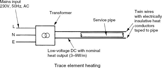
Trace element frost protection – a low-voltage electric heating element taped to the pipe surface. Used mainly for external piped services.
Wireless or radio frequency (RF) band communications are in common use (e.g. remote keyless entries, TV controls, portable telephones, burglar alarm systems, garage doors, estate gates and computer links). For heating system controls, this form of communications technology offers many benefits to both installer and property owner/end user. Not least a saving in installation time, as hard-wiring between thermostatic controls, boiler controls, motorised valves and programmer is not required. There is also considerably less disruption to the structure and making good the superficial damage from channelling walls, lifting floorboards, drilling walls and holing joists. This is particularly beneficial where work is applied to existing buildings and refurbishment projects.
In principle, a battery cell power source is used to transmit a secure, unique radio signal from the hot water storage cylinder thermostat and each of the room thermostats. This signal is recognised by a receiver which is hard-wired to switching units placed next to the boiler, pump and motorised valves. Installation cabling is therefore reduced to an absolute minimum at localised receivers only. The appearance and location of thermostats is similar to conventional hard-wired units. The capital cost of components is significantly more, but the savings in installation time will justify this expenditure.
The use of radio frequencies for communications systems in modern society is strictly controlled and regulated by operator licensing regulations to prevent interference and cross-communications. For wireless domestic heating controls this is not a problem as the unique low power signals function at around 430MHz at a short range, typically up to 30 metres. At this specification, an operating licence is not required as it satisfies the recommendations of the European Telecommunications Standards Institute, European Standard EN 300–220 for equipment in the 25 to 1000Mhz frequency band at power levels up to 500mW.
To commission RF controls, each thermostat is digitally coded and programmed to the associated signal receiver. Therefore, the controls in one building will not interfere with similar controls in adjacent buildings, and vice versa. Siting of controls will require some care as large metal objects can inhibit the signalling function. Locations of the boiler and hot water storage cylinder are obvious examples that will need consideration.
Wiring for Central Heating Systems
There are a variety of wiring schemes depending on the degree of sophistication required and the extent of controls, i.e. thermostats, motorised valves, etc. Boiler and control equipment manufacturers provide installation manuals to complement their products. From these the installer can select a control system and wiring diagram to suit their client’s requirements.
The schematic diagrams shown relate to a gravity or convected primary flow and return and pumped heating system (see page 144) and a fully pumped hot water and heating system using a three-way motorised valve (see page 172).
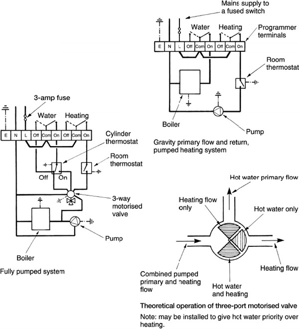
Note: may be installed to give hot water priority over heating.
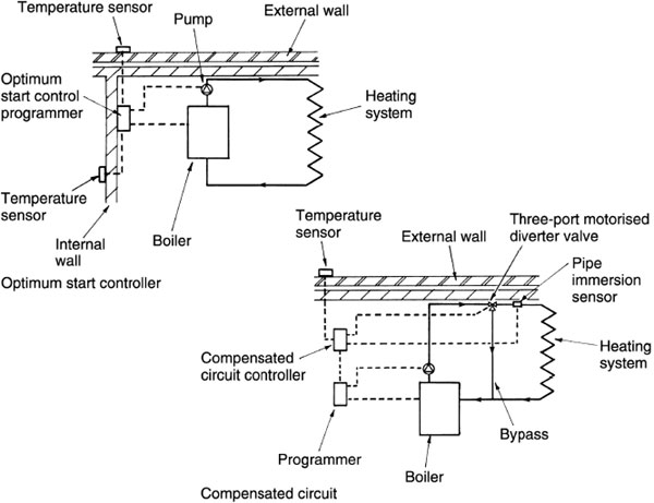
Optimum Start Controls – these have a control centre which computes the building internal temperature and the external air temperature. This is used to programme the most fuel-efficient time for the boiler and associated plant to commence each morning and bring the building up to temperature ready for occupation. The system may also have the additional function of optimising the system shutdown time.
Compensated Circuit – this system also has a control centre to compute data. Information is processed from an external thermostat/sensor and a heating pipework immersion sensor. The principle is that the boiler water delivery temperature is varied relative to outside air temperature. The warmer the external air, the cooler the system water and vice versa.
The capital cost of equipment for these systems can only be justified by substantial fuel savings. For large commercial and industrial buildings of variable occupancy the expenditure is worthwhile, particularly in the intermediate seasons of autumn and spring, when temperatures can vary considerably from day to day.
Weather compensated circuit – accurate control of indoor temperature depends on monitoring and modulating system heat input with the heat losses from a building. This differs considerably from the traditional heating system controlled solely by a thermostat. A thermostat functions relative to internal air temperature, switching on the boiler to supply water at a pre-set temperature.
Optimum comfort and economy are achieved if the heating system water is constantly circulated with temperature varied to suit occupancy needs. A balance is achieved by incorporating into the heating programme the external air temperature and internal heat gains from people, machinery, solar sources, etc. At the centre of the installation is a compensator-controlled three- or four-port motorised valve to blend the required amount of cool system return water with hot water supplied from the boiler. This ensures a continuous supply of water at the required temperature to satisfy ambient conditions. The motorised valve setting varies depending on the boiler water temperature, the system supply water temperature, internal air temperature and outdoor air temperature. The latter is measured by a thermostatic sensor fitted to a north-facing wall. Data from all four sources is computed in the compensator for positioning the motorised valve, activating the system circulator and to regulate the boiler functions.
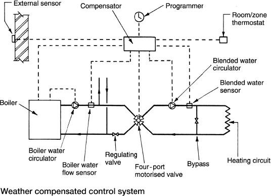
Note: Variable water temperature systems are particularly suited to underfloor heating. The heating demand is more evenly controlled through the ‘thermal’ floor than by on-off thermostatic switching.
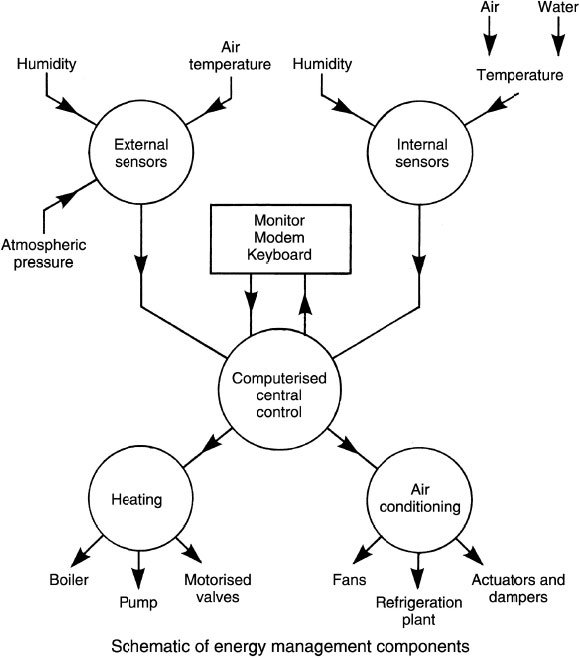
Energy management systems can vary considerably in complexity and degree of sophistication. The simplest timing mechanism to switch systems on and off at predetermined intervals on a routine basis could be considered as an energy management system. This progresses to include additional features such as programmers, thermostatic controls, motorised valves, zoning, optimum start controllers and compensated circuits. The most complex of energy management systems have a computerised central controller linked to numerous sensors and information sources. These could include the basic internal and external range shown schematically below, along with further processed data to include: the time, the day of the week, time of year, percentage occupancy of a building, meteorological data, system state feedback factors for plant efficiency at any one time and energy gain data from the sun, lighting, machinery and people.
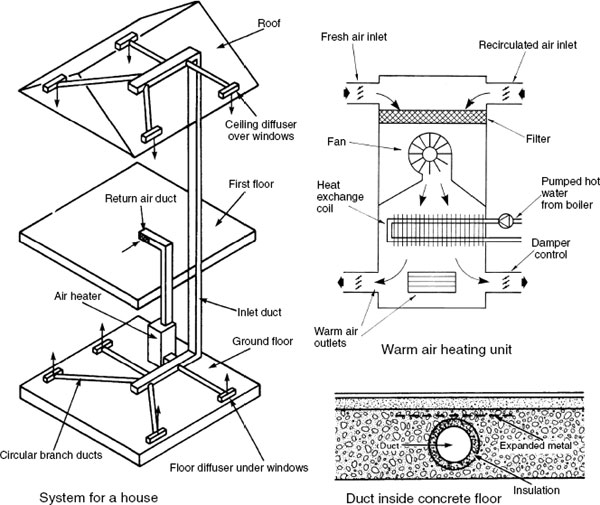
If there is sufficient space within floors and ceilings to accommodate ducting, warm air can be used as an alternative to hot water in pipes. There are no obtrusive emitters such as radiators. Air diffusers or grilles with adjustable louvres finish flush with the ceiling or floor. The heat source may be from a gas, oil or solid fuel boiler with a pumped supply of hot water to a heat exchanger within the air distribution unit. The same boiler can also be used for the domestic hot water supply. Alternatively, the unit may burn fuel directly, with air delivered around the burner casing. Control is simple, using a room thermostat to regulate heat exchanger and fan. The risk of water leakage or freezing is minimal, but air ducts should be well insulated to reduce heat losses. Positioning grilles in doors is an inexpensive means for returning air to the heater, but a return duct is preferred. Fresh air can be supplied to rooms through openable windows or trickle ventilators in the window frames. If rooms are completely sealed, fresh air should be drawn into the heating unit. The minimum ratio of fresh to recirculated air is 1:3.
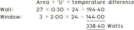
The thermal transmittance rate from the inside to the outside of a building, through the intermediate elements of construction, is known as the ‘U’ value. It is defined as the energy in watts per square metre of construction for each degree Kelvin temperature difference between the inside and outside of the building, i.e. W/m2 K. ‘U’ values can vary depending on building type and construction method and with other criteria in the SAP calculations. Guidance is provided in Approved Documents L1 and L2 to the Building Regulations.
‘U’ values for dwellings:
Limiting area weighted average |
Target or objective |
|
|---|---|---|
External walls |
0.30 |
0.20 |
Roof |
0.20 |
0.13 |
External floor |
0.25 |
0.20 |
Windows, doors |
2.00 |
1.50 |
Party wall |
0.20 |
0.20 |
Air permeability |
10.0 |
5.0 |
Window, door and roof-light areas are limited as a proportion of the overall floor area for extensions to existing dwellings to reduce the amount of heat losses. These areas are not defined for new dwellings due to considerable improvements in glazing and sealing techniques. Nevertheless, provision of glazing should be with regard to adequate daylighting and the effect of solar heat gains in summer.
E.g. A room in a dwelling house constructed with limiting ‘U’ values has an external wall area of 30m2 to include 3m2 of double-glazed window. Given internal and external design temperatures of 22°C and −2°C respectively, the heat loss through this wall will be:
Notes: Area weighted average allows for interruption in the construction, e.g. meter cupboard voids.
Limiting refers to the worst acceptable.
Target/objective, no worse than the limiting values.
Air permeability is the test reference pressure differential measured in m3 per hour per m2 of external envelope at 50 Pa.
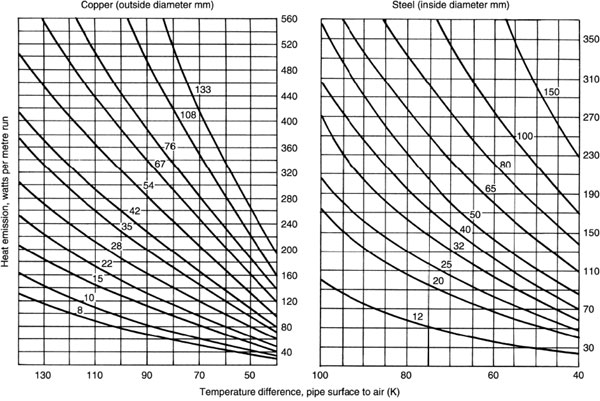
Heating Design, Heat Loss Calculations
A heat emitter should be capable of providing sufficient warmth to maintain a room at a comfortable temperature. It would be uneconomical to specify radiators for the rare occasions when external temperatures are extremely low, therefore an acceptable design external temperature for most of the UK is −1°C. Regional variations will occur, with a figure as low as −4°C in the north. The following internal design temperatures and air infiltration rates are generally acceptable:
Room |
Temperature 0°C |
Air changes per hour |
|---|---|---|
Living |
21 |
1·5 |
Dining |
21 |
1·5 |
Bed/sitting |
21 |
1·5 |
Bedroom |
18 |
1·0 |
Hall/landing |
18 |
1·5 |
Bathroom |
22 |
2·0 |
Toilet |
18 |
2·0 |
Kitchen |
18 |
2·0 |
The study in the part plan shown below can be used to illustrate the procedure for determining heat losses from a room.
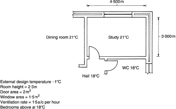
To determine the total heat loss or heating requirement for a room, it is necessary to obtain the thermal insulation properties of construction. For the room shown on the previous page, the ‘U’ values can be taken as:
External wall |
0·35W/m2 K |
Window |
2·00 |
Internal wall |
2·00 |
Door |
4·00 |
Floor |
0·25 |
Ceiling |
2·50 |
Heat is also lost by air infiltration or ventilation. This can be calculated and added to the heat loss through the structure, to obtain an estimate of the total heating requirement.
Heat loss by ventilation may be calculated using the following formula:
![]()
Note: The lower denomination, 3, is derived from density of air (1·2kg/m3) × s.h.c. of air (1000J/kg K) divided by 3600 seconds.
For the study shown on the previous page:
![]()
Heat loss through the structure is obtained by summating the elemental losses:
Total heat loss from the study = 341–55 + 436–88 = 778–43, i.e. 779 watts
Heating Design – Radiator Sizing
Radiators are specified by length and height, number of sections, output in watts and number of panels. Sections refer to the number of columns or verticals in cast iron radiators and the number of corrugations in steel panel radiators. Panels can be single, double or triple. Design of radiators and corresponding output will vary between manufacturers. Their catalogues should be consulted to determine exact requirements. The following extract shows that a suitable singlepanel radiator for the previous example of 779 watts, could be:
![]()
Selection will depend on space available. Overrating is usual to allow for decrease in efficiency with age and effects of painting.

Note: Radiators are also manufactured in 300 and 700mm standard heights.
Heating Design – Radiator Output
The tabulated heat output data in radiator manufacturers’ catalogues should be read with regard to the stated mean water to air temperature difference. This is often referred to as Delta T or ΔT. Mean water temperature can be taken as the mid-point between system flow and return temperatures. Allowing for heat losses this will be about 70°C. ΔT room design air temperature is 20°C, ΔT will be 50K, the testing criteria as defined in BS EN 442. Typical heat outputs from radiators at 50K are shown on the preceding page. These figures are about 20% lower than outputs specified at 60K.
The BS EN testing process is based on pipe connections to the top and bottom, same ends (TBSE). Other conventions are the traditional gravity circulation connections at top and bottom, opposite ends (TBOE) and the UK standard for pumped circulation to domestic radiators of bottom, opposite ends (BOE).
Radiator connections –

Ref. BS EN 442–1, 2 and 3: Specification for radiators and convectors.
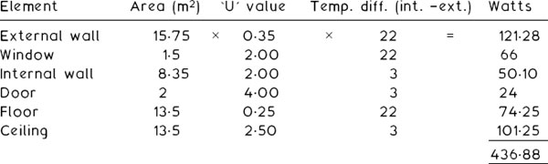
Heating Design – Approximate Heat Emission From Exposed Pipes
Note: Emission figures will vary slightly, depending on pipe quality and extent of painting.
Heating Design – Boiler Rating
To determine the overall boiler rating, the requirement for hot water (see Part 3) is added to that necessary for heating. Heating requirements are established by summating the radiator specifications for each of the rooms. To this figure can be added a nominal percentage for pipework heat losses, the amount depending on the extent of insulation.
E.g. if the total radiator output in a house is 18kW and an additional 5% is added for pipework losses, the total heating requirement is:
![]()
Given the manufacturer’s data of 80% boiler efficiency, the boiler gross heat input will be:
![]()
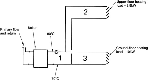
Pipes 1 – Heating flow and return at boiler
Pipes 2 – to upper floor
Pipes 3 – to ground floor
Schematic illustration, assuming a heating load of 8·9kW on the upper floor and 10kW on the ground floor, i.e. 18·9kW total.
The size of pipework can be calculated for each sub-circuit and for the branches to each emitter. Unless emitters are very large, 15mm o.d. copper tube or the equivalent is standard for connections to radiators in small bore installations. To illustrate the procedure, the drawing on the previous page allows for calculation of heating flow and return pipes at the boiler, and the supply pipes to each area of a house.
Pipes 1 supply the total heating requirement, 18·9kW.
Pipes 2 supply the upper-floor heating requirement, 8·9kW.
Pipes 3 supply the lower-floor heating requirement, 10kW.
For each pair of pipes (flow and return) the mass flow rate is calculated from:
![]()
Specific heat capacity (s.h.c.) can be taken as 4·2kJ/kg K. The temperature differential between pumped heating flow and return will be about 10K, i.e. 80°C-70°C.
Therefore, the mass flow rate for:
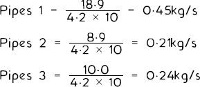
Selecting a pumped water velocity of 0·8m/s (see page 125) and copper tube, the design chart on page 196 indicates:
Pipes 1 = 35mm o.d.
Pipes 2 = 22mm o.d.
Pipes 3 = 22mm o.d.
The specification for a pump is very much dependent on the total length of pipework, summated for each section within a system. In existing buildings this can be established by taking site measurements. For new buildings at design stage, estimates can be taken from the architects’ working drawings. Actual pipe lengths plus an allowance for resistance due to bends, tees and other fittings (see page 71) provides an effective length of pipework for calculation purposes.
Using the previous example, given that pipes 1, 2 and 3 are 6m, 10m and 12m effective lengths respectively, the design chart shown on page 196 can be used to determine resistance to water flow in each of the three sections shown:
Pressure drop in pipes 1 = 200N/m2 per metre (or pascals per metre).
Pressure drop in pipes 2 and 3 = 360N/m2 per metre (Pa per m).
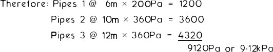
From this calculation, the pump specification is 0.45kg/s at 9.12kPa.
However, a higher figure for pump pressure will be necessary as the resistances in branch pipes to individual emitters will also need to be included. Pump selection is from manufacturers’ pump performance charts similar to that shown on page 127.
Note: The smaller the pipe diameter, the greater the pressure drop or resistance to flow.
Water Flow Resistance Through Copper Tube
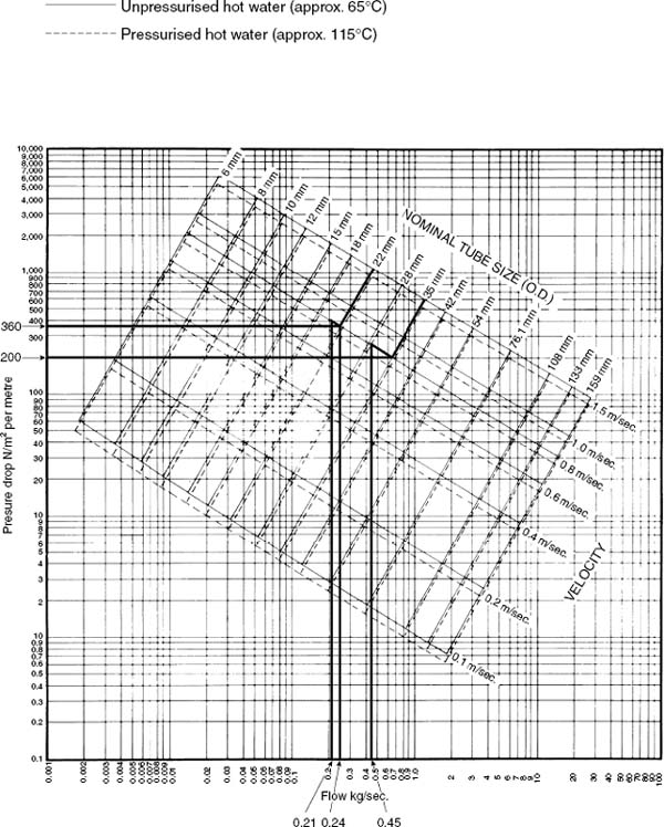
Reproduced with the kind permission of the Copper Development Association.
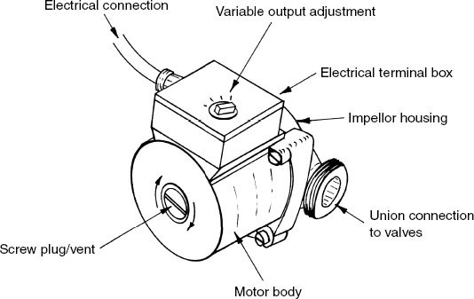
Domestic Heating Circulator/Pump
The name circulator as a component in domestic hot water and central heating systems is more realistic than pump, as the latter implies pressure of some intensity. For modest-sized installations designed for most dwellings, hot water is moved or circulated at a relatively low pressure. Nevertheless, the convenience and simplicity of the word pump has established it as preferred terminology.
Pumps are manufactured with at least three variable settings. This permits some flexibility for adjustment to individual installations and adaptability for future system alterations or extensions. It also provides a ‘one-fits-all’ application, as one model will be suitable for a wide range of different situations. Modulating pumps are also made to automatically adapt output to varying system demands. This is typical of modern installations with thermostatic radiator valves and zone valves that can isolate parts of a heating circuit (see next page).
As indicated on pages 127 and 195, pump performance is specified by pressure output in kilo-Pascals (kPa or kN/m2) or metres head (m) with a mass flow rate expressed in kilograms per second (kg/s) or litres per second (l/s).
Typical power rating, 60 to 90 watts.
Modulating pump – similar in appearance to a standard pump shown on the previous page. Internal rotation is from a glandless permanent magnet motor that has less potential to wear and relatively low energy consumption. Operation is demand controlled with a self-regulating output facility. This responds automatically to the varying load requirements of modern heating systems that incorporate numerous flow controls such as thermostats, motorised zone valves and thermostatic radiator valves. Motor speed is regulated to supply delivery pressure and flow rate in response to a heating demand that will change seasonally, daily and at different times of the day. A standard pump with a setting fixed to satisfy maximum demand is overrated for much of its running time, during which it consumes an excess of energy.
Energy label – In 2009 a European Directive introduced the following energy classification for pumps:
Class* |
Energy efficiency index (EEI) |
|
|---|---|---|
A |
< 0.4 |
Fixed speed pumps |
B |
0.4 – 0.6 |
are typically Class |
C |
0.6 – 0.8 |
D or E. Glandless |
D |
0.8 – 1.0 |
permanent magnet |
E |
1.0 – 1.2 |
motor modulating |
F |
1.2 – 1.4 |
pumps Class A. |
G |
≤ 1.4 |
|
* Classes A to G correspond with the coloured energy efficiency labels commonly displayed on domestic appliances.
EU Directive – from 2013 new and replacement pump installations are required to have an EEI ≤ 0.27 and from 2015 ≤ 0.23. Most pump manufacturers are working to an EEI of 0.20, a standard likely to be implemented when the EU Directive is reviewed in 2017.
Energy saving – Power rating is typically 10 to 20 watts, achieving a significant reduction in individual consumers’ electricity bills. On a wider scale this represents a substantial reduction in CO2 emissions.
Refs. European Ecodesign Directives for energy using appliances: 2005/32/EC and 2009/125/EC.
Note: Compatibility with boiler must be determined, particularly where used as a replacement in an existing system.
Domestic Heating Circulator/Pump – Location
Pump location is important, particularly with open-vent systems. The pump, cold feed and expansion/vent pipe positions should ensure that there is no positive or negative pump pressure where the cold feed connects to the circulatory system. This connection is known as the system-neutral point, where the only pressure is the head of water (h) from the feed cistern. If there is a significant imbalance at this point, water can pump over the expansion pipe and circulate through the feed cistern. Air may also be drawn into the system. The preferred relationship is illustrated below.
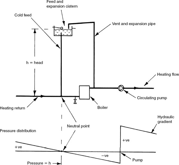
Some systems, notably older installations with higher water content heat exchangers, have the pump located on the return pipe. This should not present any problems with low circulating pressures and an adequate head of water from the feed cistern. An imbalance may occur if the system is partially closed by manual or automatic control, as pump pressure will increase in response to resistance.
Domestic Heating Circulator/Pump – Further Considerations
Water flow rates – the data on page 124 provides general guidance. For a more considerate design that has regard for noise that may be generated by water flowing, the following maximum velocities are recommended:
Pipe diameter (mm) |
Water velocity/flow rate (m/s) |
|---|---|
1 0 |
0·50 |
1 5 |
0·55 |
22 |
0·70 |
28 |
0·75 |
35 |
0·80 |
42 |
0·90 |
54 |
1·00 |
Note: Pipe diameter is expressed as copper outside diameter. For other materials the nearest equivalent size is acceptable.
Pump position and installation –
Low parts of a circuit are to be avoided as any sediment could accumulate in the pump body and contribute to wear.
Accessible for maintenance, i.e. not secreted under floor-boards or behind cupboards.
Away from a wall or floor as pump vibration may generate noise through the structure.
Isolating valves provided each side of the pump to avoid draining the whole system should the pump need to be removed.
Preferably in a vertical pipe to ensure that the circulator shaft is horizontal. This reduces the load on the shaft bearings and allows air to purge itself from the rotor and impellor housing.
Note: Sometimes due to system restrictions it may only be possible to place the pump in horizontal pipework. In these situations the circulator shaft should not be less than horizontal. Just a few degrees higher at the vent plug end is better than allowing the shaft to suspend and possibly wear the shaft and bearing prematurely. If the motor is above the pump its whole weight bears on the impellor and this too will cause premature wear. Also, any system air could become trapped at the top of the pump body.
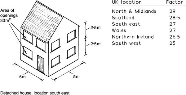
Boiler Rating – Approximate Guide for Domestic Premises
A simple and reasonably accurate estimate for determining boiler size. Procedure:
Establish dwelling dimensions and factor for location –
UK location
Factor
North & Midlands
29
Scotland
28·5
South east
27
Wales
27
Northern Ireland
26·5
South west
25
Approximate heat losses:
Openings area (30m2) ×Openings ‘U’ value (2.00 ave.)* = 60 (A).
Gross wall area (100m2) – Openings area (30m2) ×Wall ‘U’ value (0.35)* = 24.5 (B).
Roof length (5m) × Roof width (5m) × Roof’ U 1 value (0.25)* = 6.25 (C).
Floor length (5m) × Floor width (5m) × Standard correction factor (0.7) = 1 7.5 (D).
(For ceiling and floors in a mid-position flat, use zero where not exposed.)
Summate fabric losses: A + B + C + D = 108.25.
Multiply by location factor: 108.25 × 27 = 2922.75 watts.
Calculate ventilation losses:
Floor area (25m2) × Room height (2.5m) × No. of floors (2) = Volume (125m3) × Standard ventilation correction factor (0.25) × Location factor (27) = 843.75 watts.
Boiler input (net) rating = 2922.75 + 843.75 + 2000 (watts for hot water) + calcs. for any extension to building = 5766.50 watts or 5.77 kW.
* See page 187 for current ‘U’ values.
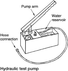
Pressure Testing Installations
Testing medium – water is preferred to air, as water is virtually incompressible. In addition, about 200 times more energy would be stored in compressed air at the same pressure and volume as for water. This could have a damaging effect on personnel and property if a component leaked or failed.
Where premises are particularly sensitive to water leakage, a low-pressure air test can be undertaken before applying a hydraulic test.
Procedure
Disconnect ancillary equipment that may not be designed to withstand test pressures, e.g. shower, boiler, etc. Manufacturer’s data should be consulted.
Check all system high points for location of air vents.
Blank or plug any open ends including float valves. Close valves where subsections only are being tested.
Open all valves in the enclosed section under test.
Attach test pump to a convenient point.
Start filling the system by pump priming and replenishing the pump water reservoir.
Ventilate air from high points until water shows.
When the system is full, raise the pressure as required.
If pressure falls, check joints, valves, etc. for leakage.
When the test is satisfied, ensure the appropriate documentation is signed.
Test requirements
Rigid pipes – provide an internal water pressure at the lowest point in the system at 50% above normal operating pressure. This should hold for one hour. For example, 1 bar (10m or 100kPa) operating pressure requires a 1.5 bar (15m or 150kPa) test pressure.
Plastic pipes – elastic by nature, will expand to some extent under pressure. Therefore the test procedure for rigid pipes is inappropriate. Either of the following tests, A or B, is acceptable:
Test A – test pressure as for rigid pipes is applied and maintained for 30 minutes. After this time, pressure is reduced by one-third. For another 90 minutes the test is satisfied if there is no further reduction in pressure. Test B – required test pressure is applied and maintained for 30 minutes. Test is satisfied if:
pressure drops <0·6 bar (60kPa) after a further 30 minutes, and
pressure drops <0·2 bar (20kPa) after a further 120 minutes, and
there is no visible leakage.
Application – underground and above-ground systems of water pipework.
Ref. Water Supply (Water Fittings) Regulations, Schedule 2, Paragraph 12.
Corrosion in Central Heating Systems
Boilers with a cast iron heat exchanger used with an indirect sealed system are unlikely to corrode. However, some electrolytic reaction between copper pipes and steel heat exchangers in boilers and pressed steel radiators is possible. In addition, some corrosion of steel can occur where minute amounts of air enter the system. This may occur:
through undetected leakage at pipe joints;
from air present in solution;
from air dissolving into water contained in the feed and expansion cistern.
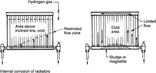
The initial indication of internal corrosion is one or more radiators failing to get hot and a need for frequent ‘bleeding’ through the air valve. Corrosion produces hydrogen gas. This may be detected by holding a lighted taper to the draught escaping at the air valve. Caution should be observed when effecting this test and, if the taper is seen to burn with a blue flame, hydrogen is present. Air will not burn.
Another characteristic of corrosion is black sludge accumulating in the bottom of radiators. This is known as magnetite and it may also obstruct circulating pipes. Magnetite is the metallic breakdown of steel radiator walls. In addition to blockage and corrosion, magnetite is drawn to the magnetic field of the circulating pump where its abrasive presence may cause the impellor to fail.
Corrosion in heating systems can be prevented or at least considerably reduced, by introducing a proprietary inhibitor to the feed and expansion cistern as the system is filled. With sealed systems the inhibitor can be introduced with a funnel and hose temporarily connected to a high-level radiator (see page 135).
Ref. BS 7593: Code of practice for treatment of water in domestic hot water central heating systems.