

Direct System of Hot Water Supply
Indirect System of Hot Water Supply
Unvented Hot Water Storage System
Expansion and Temperature Relief Valves
Primatic Hot Water Storage Cylinder
Medium-and High-Rise Building Supply Systems
Sealed Indirect Hot Water System for a High Rise Building
Electric and Gas Water Heaters
Legionnaires Disease in Hot Water Systems
Water expands with changes in temperature. At 4°C water is at its most dense. At temperatures below 4°C down to zero or freezing, water expands about 9% (approximately 1/10) by volume. This is why underground supplies require adequate ground cover and externally exposed water pipes require insulation to prevent damage. At temperatures between 4°C and 100°C or boiling, water expands by about 4% (approximately 1/25) by volume and is significantly less dense – see table below. This degree of expansion and reduction in density is the principle of convective water circulation in elementary hot water systems.
Temperature (°C) |
Density (kg/m3) |
|---|---|
0 |
999·80 |
4 |
1000·00 |
10 |
999·70 |
20 |
998·20 |
30 |
995·00 |
40 |
992·20 |
50 |
987·50 |
60 |
983·20 |
70 |
977·50 |
80 |
971·80 |
90 |
965·60 |
100 |
958·00 |
The following formula can be used to calculate the amount that water expands in a hot water system:
Example: A hot water system containing 15m3 of water, initially at 10°C to be heated to 80°C.
![]()
Hot water and heating systems must incorporate a means for accommodating expansion. A fail-safe mechanism must also be provided should the initial provision malfunction.
Heated wholesome water (defined on page 26) must be available at:
Sanitary appliances for washing, i.e. bath, basin, bidet and shower.
Any sink used for the preparation of food.
Systems of hot water supply must be provided with controls to regulate water temperature in normal use. In the event of controls malfunctioning, temperature and pressure safety devices are required. Installations must be able to withstand the effects of higher than normal operating temperature and pressure.
Vented system – operates at atmospheric pressure with an open vent and hot water expansion pipe above the feed cistern. This pipe contains the excess of hot water on heating. A water temperature control thermostat is fitted to the hot water storage cylinder (set at 60–65°C). The boiler is fitted with a thermostatic control (manually set at about 80°C) to prevent the water from boiling. The boiler pipework has a pressure relief valve (see page 85 and accompanying note).
Unvented systems – these are sealed systems that have gained in popularity since the 1980s. Hot water expansion is accommodated by a cushion of air in a spherical vessel (see page 154). In addition to a water temperature control thermostat, the hot water storage cylinder must have a temperature and pressure relief valve. These may combine as one valve that satisfies both functions and it should discharge through a tundish and safely into the atmosphere. Further safety features are the boiler control thermostat and a non self-resetting over-temperature energy cut-out to disconnect the supply of heat to the storage vessel.
Note: Hot water cylinders specifically for unvented systems are available factory supplied with all relevant safety accessories, whereas traditional vented systems rely on the competence of the installer for the correct fitting of safety devices.
Direct System of Hot Water Supply
The hot water from the boiler mixes directly with the water in the cylinder. If used in a ‘soft’ water area the boiler must be rust-proofed. This system is not suited to ‘hard’ waters, typical of those extracted from boreholes into chalk or limestone strata. When heated the calcium precipitates to line the boiler and primary pipework, eventually ‘furring up’ the system to render it ineffective and dangerous. The storage cylinder and associated pipework should be well insulated to reduce energy losses. If a towel rail is fitted, this may be supplied from the primary flow and return pipes.

Note: All pipe sizes shown are for copper outside diameter.
Indirect System of Hot Water Supply
This system is used in ‘hard’ water areas to prevent scaling or ‘furring’ of the boiler and primary pipework. Unlike the direct system, water in the boiler and primary circuit is not drawn off through the taps. The same water circulates continuously throughout the boiler, primary circuit and heat exchange coil inside the storage cylinder. Fresh water cannot gain access to the higher temperature areas where precipitation of calcium would occur. The system is also used in combination with central heating, with flow and return pipes to radiators connected to the boiler. Boiler water temperature may be set by thermostat at about 80°C.
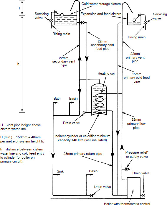
*In the unlikely occurrence of the primary flow and vent becoming obstructed, water expansion could also be accommodated up the cold feed pipe.
Unvented Hot Water Storage System
The Building Regulations, Approved Document G3, permit the installation of packaged unit unvented hot water storage systems which have been accredited by the British Board of Agrément (BBA) or other European Organisation for Technical Approvals (EOTA) member bodies. Components should satisfy BS EN 12897: Water supply. Specification for indirectly heated unvented (closed) storage water heaters. A system of individual approved components is also acceptable. Safety features must include:
Stored hot water temperature control between 60 and 65°C.
Non self-resetting over temperature cut-out to close off the fuel supply if the boiler thermostat fails.
Expansion and temperature relief valves to operate at 95°C.
Check valves on water main connections.
Note: A supplementary 950°C boiler limit thermostatic control may be fitted by the manufacturer.
The system is less space consuming than conventional systems and saves installation costs as there are no cold water storage and expansion cisterns. In addition to satisfying the Building Regulations, the local water authority should be consulted for approval and to ensure that there is adequate mains pressure.

UHWSS – Further Details > 15 Litres Storage
Installation – by suitably qualified person in possession of a registered operative identity card/certificate, issued by a recognised assessment body such as the Chartered Institute of Plumbing and Heating Engineering or the Construction Industry Training Board.
Notice of installation – given to the local authority Building Control Department. Building Regulation G3 – Hot Water Supply and Systems, requires a competent installer, precautions to prevent water temperature from exceeding 100°C and any hot water discharge from safety devices to be conveyed safely and visibly.
Water supply – direct feed from water main, therefore no atmospheric vent pipe and no cold water storage cistern.
Water expansion – accommodated by suitably sized expansion vessel. Some units operate with an internal air gap (see next page).
Systems – direct heated by immersion heater, or indirect from a central heating boiler.
Storage cylinder materials – stainless steel, glass/vitreous enamel-coated steel or heavy-gauge copper.

Controls –
Temperature and pressure-relief valve.
Expansion/pressure-relief valve.
Cylinder temperature regulating thermostat manually set to operate the zone valve at 60–65°C.
Over-temperature cut-out thermostat, pre-set to operate the zone valve at 85°C.
For all hot water systems, especially those exceeding 15 litres storage capacity, a purpose-made hot water storage cylinder designed with provision for an ‘air gap’ or ‘bubble top’ is an effective alternative to installing a separate expansion vessel.
Typical installation –

As the water expands on heating, the volume of trapped air is compressed to provide adequate delivery pressure and flow. After some time, the air may become depleted due to turbulence by water movement through the hot water storage cylinder. This will be noticed by the pressure-relief valve discharging. The ‘air gap’ is recharged by draining the system and refilling. Some manufacturers fit a floating baffle between the water and the air, to reduce the effect of turbulence.
Expansion and Temperature-relief Valves
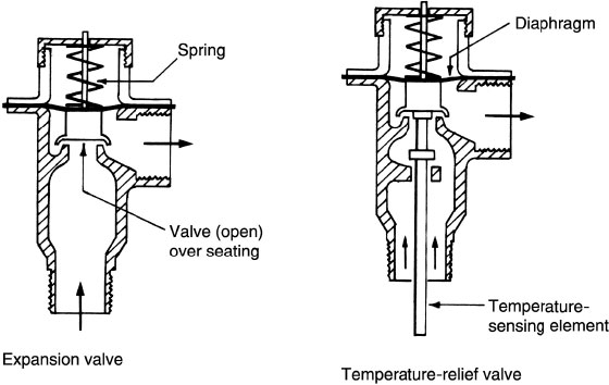
Expansion devices in hot water systems are designed as a safe means for discharging water when system operating parameters are exceeded, i.e. in conditions of excess pressure and/or temperature.
Expansion valve – Care should be taken when selecting expansion or pressure-relief valves. They should be capable of withstanding 1·5 times the maximum pressure to which they are subjected, with due regard for water mains pressure increasing overnight as demand decreases.
Temperature relief valve – These should be fitted to all unvented hot water storage vessels exceeding 15 litres capacity. They are normally manufactured as a combined temperature and pressure-relief valve. In addition to the facility for excess pressure to unseat the valve, a temperature-sensing element is immersed in the water to respond at a pre-set temperature of 95°C.
Discharge from these devices should be safely controlled and visible, preferably over a tundish, as shown on page 154.
Ref. BS 6283-2: Safety and control devices for use in hot water systems. Specifications for temperature-relief valves for pressures from 1 bar to 10 bar.
Pressure-reducing valves are otherwise known as pressure regulators. PRVs can be applied to many different piped services including gas, compressed air, water and steam. These applications may range from relatively simple installations such as mains water-supplied domestic unvented hot water storage systems, to larger scale industrial steam and district heating schemes.
High pressure is needed to overcome the resistances of long lengths of pipe distribution, changes in direction, valves, etc. For local distribution, the pressure must be reduced to:
Prevent undue wear and damage to the lighter gauge fittings and fixtures at the end use.
Provide a maximum safe working pressure to prevent injury to end users.
Regulate supplies at a constant value or desirable secondary pressure, irrespective of inlet pressure variations and changes in demand.
Function and installation

Outlet reduced pressure acts on the underside of the diaphragm.
Control spring opposes the reduced pressure.
Reduced pressure and control spring setting effect the position of the valve and flow condition.
A strainer is used to filter out and trap fluid-suspended debris, pipe scale and carbonate deposits from hard water. This facility is essential to prevent component wear by erosion and abrasion, and interference with the efficient operation of pipe system controls. Strainers are a standard installation on processing plant and other industrial applications. There has been little need for strainers in domestic systems, until the use of items such as thermostatic mixing valves, shower mixers, check valves and pressure-reducing valves have become standard. To protect the sensitivity of these units, most manufacturers integrate a means of filtering within the casting. Otherwise, an independent pipeline strainer of the type shown can be installed upstream of the unit.
Typical pipeline strainers

BS 1566-1: Copper indirect cylinders for domestic purposes. Open-vented copper cylinders. Requirements and test methods.
BS 1566-2: Copper indirect cylinders for domestic purposes. Specification for single-feed indirect cylinders.
BS 417-2: Specification for galvanised low carbon steel cisterns, cistern lids, tanks and cylinders.

Direct cylinders have no coil or annular heat exchangers. They can be identified with female pipe threads for the primary flow and return connections. For domestic use: copper – 74 to 450 litres capacity, galvanised steel – 73 to 441 litres capacity. Direct and indirect cylinders for industrial and commercial applications are manufactured in copper and galvanised steel in capacities up to 4500 litres.
Notes:
Copper and galvanised (zinc-plated) steel pipes and components should not be used in the same installation. In addition to electrolytic action between the dissimilar metals, pitting corrosion caused by tiny particles of dissolved copper settling on the galvanising will produce local cells which dissolve the zinc and expose the steel to rusting.
Copper and galvanised steel cylinders normally incorporate an aluminium and a magnesium sacrificial anode, respectively. These are designed to deteriorate over sufficient time to allow a protective coating of lime scale to build up on the exposed surfaces.
Primatic Hot Water Storage Cylinders
BS 1566-2: Specification for single feed indirect cylinders.
An indirect hot water system may be installed using a ‘primatic’ or single-feed indirect cylinder. Conventional expansion and feed cistern, primary cold feed and primary vent pipes are not required, therefore by comparison, installation costs are much reduced. Only one feed cistern is required to supply water to be heated indirectly, by water circulating in an integral primary heater. Feed water to the primary circuit and boiler is obtained from within the cylinder, through the primary heater. The heat exchanger inside the cylinder has three airlocks which prevent mixing of the primary and secondary waters. No corrosion inhibitors or system additives should be used where these cylinders are installed.

Indirect Hot Water System for a Three-storey Building
For larger buildings a secondary circuit will be required to reduce ‘dead-legs’ and to maintain an effective supply of hot water at all outlets. Convection or thermo-siphonage may provide circulation, but for a more efficient service a circulatory pump will be necessary. In buildings which are occupied for only part of the day (e.g. schools, offices, etc.), a time control or programmer can be used to regulate use of the pump. In addition, one of the valves near the pump should be motorised and automatically shut off with the pump and boiler when hot water is not required. All secondary circuits should be well insulated to reduce heat loss through the pipework. A heating installation can operate in conjunction with this system, but may require duplication of boilers or separate boilers for each function.

Indirect Supplementary Hot Water System
Hot water provision in moderately large buildings such as spacious houses, small hotels, hostels and other situations where demand is periodically high, can be from a large storage cylinder or cylinders installed in duplicate. Alternatively or additionally, depending on requirements, a supplementary storage vessel may be strategically located at high level. This vessel is relatively small, containing no more than 20% of the total design capacity.
Advantages over a single storage facility:
Smaller secondary flow and return distribution pipes.
Less concentrated dead load on the structure.
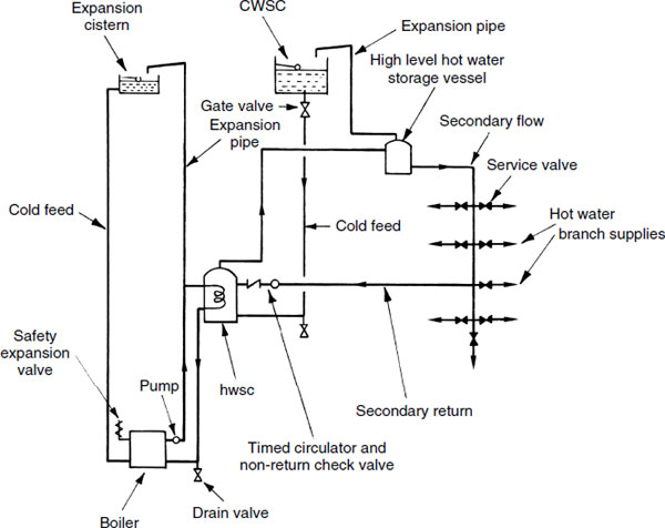
Sealed Indirect Hot Water System for a High-rise Building
For convenience and to reduce wear on fittings, the maximum head of water above taps and other outlets is 30m. This is achieved by using intermediate or break-pressure cisterns for each sub-circuit. Head tanks are provided to ensure sufficient volume of stored hot water and adequate delivery to the upper floors. Compared with conventional installations a considerable amount of pipework and fitting time can be saved by using an expansion vessel to absorb expansion of water in the primary circuit. However, the boiler and calorifiers must be specified to a high-quality standard to withstand the water pressure. All pipework and equipment must be well insulated.

Primary Thermal Store Water Heaters
Principle – cold water passes through a heat exchanger (pipe coil) heated by hot water surrounding the coil.
Types:
Natural convection –

Pumped circulation (internal) –

Pumped circulation (external) [see also page 232] –
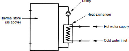
Principle for providing hot water only –
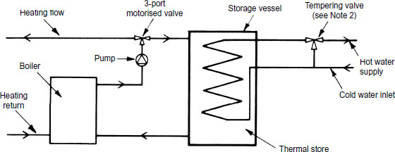
Principle for hot water supply and central heating functions –
Note 1: Examples of boiler circuit filling, expansion and safely facilities omitted, but are shown elsewhere in Part 2 and Part 3.
Note 2: Some thermal store systems, notably those connected to solar heat collectors and to solid fuel boilers may produce stored hot water above 80°C. Therefore, as control of the heat source may not be that reliable, the hot water outlet should be fitted with a tempering valve (see page 404) to maintain the hot water supply at less than 60°C.
Ref. Building Regulations Part G, Approved Document G3.
Primary Thermal Store Water Heating
Thermal store – sometimes referred to as an inertia or a buffer vessel. A hot water storage facility located between primary energy/heat source(s) and secondary heat load, i.e. hot water supply to taps and other fittings and possibly for space heating circuit.
Energy source – conventional fossil fuelled boiler as shown on the preceding two pages. These installations are more energy efficient where supplemented with a low or zero carbon alternative energy source, such as a heat pump or solar panels. Alternative energy can be the sole source if it is sufficiently effective.
Installation principle combining a conventional fossil-fuelled boiler with a solar energy source –

See Notes 1 and 2 on previous page.
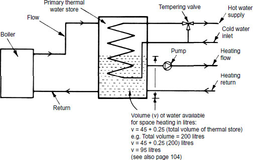
Primary Thermal Storage for Hot Water and Heating
Schematic principle of combining high and low temperature heat sources of energy for hot water thermal storage. Provides a domestic hot water supply to taps and other fittings through a heat exchanger within the thermal store. A separate circuit connected directly to the thermal store is for space heating –

Typical buffer storage capacity of hot water for heating (litres) –

Note: ![]() T in this context refers to the temperature difference between heating flow and return. With pumped circuit temperatures typically 80°C and 70°C respectively,
T in this context refers to the temperature difference between heating flow and return. With pumped circuit temperatures typically 80°C and 70°C respectively, ![]() T = 10K.
T = 10K.
Cast iron sectional – made up of a series of hollow sections, joined together with left- and right-hand threaded nipples to provide the heat capacity required. When installed, the hollow sections contain water which is heated by energy transfer through the cast iron from the combusted fuel. Applications: domestic to large industrial boilers.
Steel shell, fire or flame tube – hot combusted fuel and gases discharge through multiple steel tubes to the extract flue. Heat energy from the burnt fuel transfers through the tube walls into cylindrical waterways. Tubes may be of annular construction with water surrounding a fire tube core. Uses: commercial and industrial buildings.
Copper or steel water tube – these reverse the principle of fire tubes. Water circulates in a series of finned tubes while the combusted fuel effects an external heat transfer. These are typical of the heat exchangers in domestic boilers.
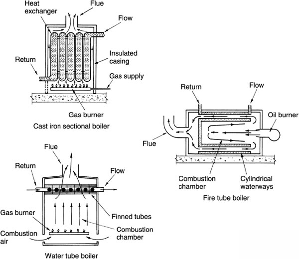
All these boiler types may be fired by solid fuel, gas or oil.
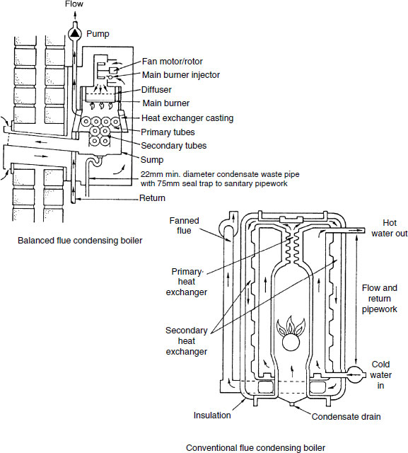
Condensing boilers have a greater area of heat transfer surface than conventional boilers. In addition to direct transfer of heat energy from the burning fuel, heat from the flue gases is used as secondary heating to the water jacket. Instead of the high-temperature (200–250°C) flue gases and water vapour discharging to the atmosphere, they are recirculated around the water jacket by a fan. This fan must be fitted with a sensor to prevent the boiler from firing in the event of failure. Condensation of vapour in the flue gases is drained to a suitable outlet. The overall efficiency is about 90%, which compares well with the 75% expected of conventional boilers. However, purchase costs are higher, but fuel savings should justify this within a few years.
Refs. BS 6798: Specification for installation and maintenance of gas-fired boilers of rated input not exceeding 70kW net.
Building Regulations. Approved Document H1: Foul Water Drainage, Section 1 – Sanitary pipework.
Otherwise known as high-efficiency boilers.
Originally developed in the 1930s. Lack of technological advances and less concern about the effect of consuming fuel limited interest until the fuel crises of the 1970s.
Introduced to the domestic market in the early 1980s. Slow to establish due to relatively higher purchase cost. From 2005, virtually compulsory for new installations, to satisfy SEDBUK efficiency bands A and B. From 2010, band A only is acceptable.
Extracts heat from flue gases to gain from the secondary heating effect.
Heat exchanger must be corrosion resistant, i.e. stainless steel or aluminium to resist the acidity of condensate. Cast iron and copper are only suitable in non-condensing boilers with high flue gas temperatures which are unaffected by condensation.
Non-corrosive plastic condensate waste-pipe required. Waste usually connected to a siphon which discharges condensate in one go from a 150ml sump. This reduces the possibility of a drip discharge freezing.
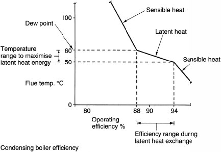
Least efficient condensing boiler has about the same efficiency as the most efficient non-condensing boiler.
Condensing boilers are at their most efficient with low return water temperatures. This effects most condensation. Therefore, they are best used with modulating controls as described on page 184.
About 80% energy exchange occurs as combusted gas at temperatures above 200°C effect the primary heat exchange. The secondary heat exchange adds about another 5% as the fanned flue gases reduce to about 55°C as they pre-warm the returning system cool water. With this temperature reduction the flue gases condense and dew point occurs (steam turns to water), adding about another 5% in latent energy transfer.
The gas burner has to impart less energy to raise the temperature at the primary heat exchange, hence fuel savings and less CO2 and NOx emissions from the flue.
Controls –
Non-condensing boilers are efficiently controlled with thermostatic valves, thermostats and an interlock facility. The boiler is switched on and off relative to internal air temperature. High-temperature water is delivered to emitters.
Condensing boilers are at their most efficient when enabled to run for sustained periods with a moderate flow water temperature and low return water temperature. They are ideally suited to modulating, weather-compensated control systems.
Flue discharge has a distinct plume or cloud of moisture droplets. May be a problem with neighbouring properties.
Flue slopes back slightly towards the boiler to discharge any condensation from the flue duct into the condensate drain.
Typical SEDBUK factors:
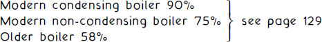
A non-condensing boiler loses at least 20% of heat energy produced into the flue. Therefore these boilers are 80% efficient at best. Approximately half the heat energy that would be otherwise lost in the flue is recovered by a condensing boiler. Therefore these boilers are approximately 90% efficient.
Approximate number of households in UK with a gas boiler = 14 million.
Typical annual household production of CO2 with a non-condensing boiler = 5 tonnes.
Total potential CO2 emissions = 70 million tonnes.
Typical annual household production of CO2 with a condensing boiler = 3 tonnes.
Total potential CO2 emissions = 42 million tonnes.
Therefore, in addition to fuel savings, condensing boilers represent a potential for an annual reduction in polluting or greenhouse gases of 28 million tonnes.
Note: Oil-fired condensing boilers are also marketed with specifications to satisfy current energy use requirements.
This system saves considerably in installation time and space, as there is no need for cisterns in the roof space, no hot water storage cylinder and associated pipework. The ‘combi’ gas boiler functions as an instantaneous water heater only heating water as required, thereby effecting fuel savings by not maintaining water at a controlled temperature in a cylinder. Water supply is from the mains, providing a balanced pressure at both hot and cold water outlets. This is ideal for shower installations. Boiler location may be in the airing cupboard, leaving more space in the kitchen. The system is sealed and has an expansion vessel which is normally included in the manufacturer’s pre-plumbed, pre-wired package for simple installation. Further control details are shown on page 176.
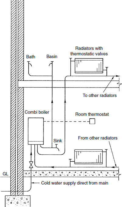
Note: The boiler incorporates a pump, expansion vessel and electronic controls. Cold water supply to bath, basin and sink has been omitted for clarity.
To prevent user inconvenience waiting for the cold water ‘dead-leg’ to run off and to prevent water wastage, long lengths of hot water distribution pipework must be avoided. Where cylinder to tap distances are excessive, a pumped secondary flow and return circuit may be installed with minimal ‘dead-legs’ branching to each tap. The pipework must be fully insulated and the circulation pump timed to run throughout the working day, e.g. an office system could be programmed with the boiler controls, typically 8.00 am to 6.00 pm, five days a week. A non-return valve prevents reverse circulation when the pump is not in use.
Nominal inside pipe dia. (mm) |
Equivalent copper tube outside dia. (mm) |
Max. length of secondary flow without a return (m) |
|---|---|---|
10 |
12 |
20 |
>10 to 19 |
>12 to 22 |
12 |
>19 to 25 |
>22 to 28 |
8 |
>25 |
>28 |
3 |

Dual installations or duplication of plant and equipment is required in buildings where operating efficiency is of paramount concern. With this provision, the supply of hot water in hotels, commercial buildings, offices, etc. is ensured at all times, as it is most unlikely that all items of plant will malfunction simultaneously. It may also be necessary to divide the design capacity of plant to reduce the concentration of structural loads. Each boiler and calorifier may be isolated for repair or renewal without disturbing the function of the others. Therefore when designing the system it is usual to oversize plant by up to one-third, to ensure the remaining plant has reasonable capacity to cope with demand. There is also the facility to economise by purposely isolating one boiler and calorifier during periods when a building is only part occupied.

An electric immersion heater may be used within a conventional hot water storage cylinder. Alternatively, individual or self-contained open outlet heaters may be located over basins, baths or sinks. Combined cistern-type heaters can be used to supply hot water to several sanitary appliances. Energy conservation is achieved with an integral thermostat set between 60 and 65°C. This temperature is also sufficient to kill any bacteria. The immersion heater must have a circuit protective conductor to earth and the cable supplying the heating element must be adequate for the power load. A cable specification of 2·5mm2 is normally adequate with a 20 amp double pole control switch supplied direct from the consumer’s unit or fuse box. Overload protection at the consumers unit is a 16 amp fuse or circuit breaker for a 3kW element and 20amp for a 4kW element.
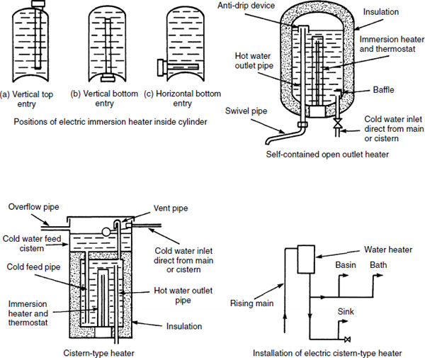
Ref. BS 3198: Specification for copper hot water storage combination units for domestic purposes.
The cistern-type heater should be located with the water level at least 1·5m above the water draw-off taps. If there is insufficient space to accommodate this combination unit, a smaller pressure-type water heater may be fitted. These are small enough to locate under the sink or elsewhere in the kitchen. They have two immersion heaters. The upper element of 500 watts rating is for general use supplying hot water to the basin, sink and other small appliances. The lower element of 2500 watts may be on a timed control to provide sufficient hot water for baths. The pressure heater is supplied with cold water from a high-level cistern.

Immersion heaters – safety cut-out. Since 2004, immersion heater manufacturers are required to incorporate an additional integral safety device, independent of the main thermostat. This brings immersion heaters for vented water heating into line with the requirements for unvented water heaters.
Function – if the main thermostat fails, water will boil, with considerable damage potential to personnel, the installation and premises. The manufacturer’s pre-set safety cut-out is designed to prevent water in a hot water storage vessel from exceeding 98°C. It must not reset automatically.
Methods – either:
A ‘one-shot’ thermal cut-out or thermostat. This is principally a fusible link which melts or ruptures at a predetermined temperature, or
A manually resettable cut-out or thermostat which responds to critical temperature change to break electrical contact.
Ref. BS EN 60335-2-73: Household and similar electrical appliances. Safety. Particular requirements for fixed immersion heaters.
Instantaneous water heaters are relatively compact non-storage units suitable for use with individual sinks, basins and showers. For user safety they are fitted with a pressure switch to disconnect the electricity if the water supply is interrupted and a thermal cut-out to prevent the water from overheating. Mains pressure to these units should be maintained below 400kPa (4 bar). In some high-pressure supply areas this will require a pressure-reducing valve to be installed on the service pipe. Some expansion of hot water will occur while the unit is in use. This can be contained if there are at least 3 metres of pipework before the unit and the closest cold water draw-off. If this is impractical, an expansion vessel may be used. For more details of electric shower installations see pages 392 and 393.

Electric Water Heating – Economy 7 and Economy 10
Industrial, commercial and domestic demand for electricity is considerably reduced overnight. Therefore during this time, the electricity supply companies can market their spare capacity as off-peak electricity by selling it at a reduced rate – approximately half the cost of the standard daytime tariff. Supplies are adapted to operate through a programmer or time control which diverts the electricity to a special off-peak or white meter, usually from midnight to 7 a.m. In order to maximise the benefit, slightly larger than standard capacity hot water storage cylinders of 162 or 190 litres are recommended. To conserve energy, these cylinders must be thoroughly insulated and the immersion heaters fitted with integral thermostatic control. If supplementary hot water is required during the day, this can be provided by a secondary immersion heater at standard supply tariff.

Economy 10 – some suppliers provide this as a discounted tariff variation to Economy 7. This operates for three hours in the afternoon, two hours in the evening and five hours overnight. See also page 533.
The secondary immersion heater or boost heater is close to the top of the cylinder to ensure that only a limited quantity of water is heated at standard tariff. To maximise economy, the off-peak thermostat is set at 65°C and the boost thermostat at 60°C.
When the hot water outlet is opened, cold water flows through a venturi fitting. The venturi contains a diaphragm which responds to the flow differential pressure and this opens the gas valve. A pilot flame ignites gas flowing through the burner which heats the water as it passes through the heat exchanger. Installation can be direct from the water main or from a cold water storage cistern. A multi-point system has the hot water outlet suppling several appliances.
A gas circulator can be used to heat water in a storage cylinder. They are usually fitted with an economy or three-way valve. This gives optional use of water circulation through a high or low return pipe for variable hot water storage volume. Domestic installations may be in the kitchen, with vertical flow and return pipes to a storage cylinder in the airing cupboard.
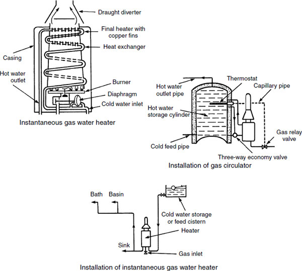
Ref. BS EN 26: Gas-fired instantaneous water heaters for the production of domestic hot water, fitted with atmospheric burners.
The storage type of gas water heater is a self-contained unit and is therefore simpler and quicker to install than a gas circulator. Capacities range from 75 to 285 litres. The smaller units are single-point heaters for supplying hot water to an individual sink or basin. Larger, higher rated storage heaters can be used to supply hot water to a bath, basin, sink and shower. These are called multi-point heaters. They may also be installed in flats up to three storeys, with cold water supplied from one cistern. A vent pipe on the cold feed will prevent siphonage. To prevent hot water from the heaters on the upper floors from flowing down to the heater on the ground floor, the branch connection on the cold feed pipe must be above the heaters.
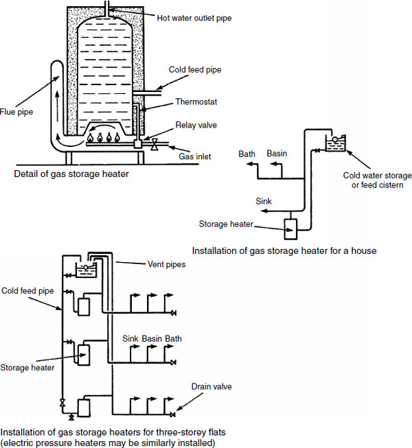
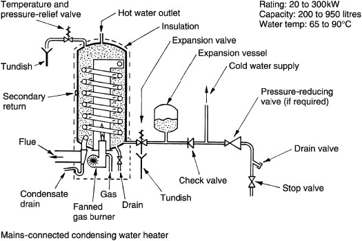
Condensing water heater – a variation on the multi-point-type heater. The condensing heater is a hot water storage vessel, capable of very rapid heat recovery.
Application – typical examples include small hotels, schools, residential homes, student halls of residence, camp sites and sports centres.
Function – a fanned gas burner discharges into a stainless steel combustion chamber within a cylindrical water storage vessel. From the combustion chamber the burnt gases descend into a stainless steel spiral to exit at low level through a flue. Condensate from the flue is trapped and discharged to a drain.
Controls –
Automatic electric ignition in response to a water temperature thermostat.
Limit thermostat.
Overheat safety thermostat and warning light.
Fan failure device and warning light.
Manual on/off switch.
Water supply – either:
- Cistern, gravity feed pipe and atmospheric vent and expansion pipe, or
- Direct connection to an unvented mains supply. Unvented supplies require backflow prevention (check valve), an expansion vessel and an expansion valve. A pressure and temperature relief valve must also be fitted to the hot water outlet to discharge safely into a tundish.
Solar energy systems reduce the environmental impact of buildings by providing a viable energy alternative to reliance on diminishing fossil fuel reserves. They also provide a fuel cost saving for the building user.
Energy from the sun can be used for heating swimming pools, preheating ventilation air and for space heating. The most common application in the UK is for heating water for domestic use. Many new homes feature solar systems as contributory to their energy performance criteria. However, a conventional back-up heat source from a boiler is still required to compensate when solar energy capture is limited.
Operating and installation principle –

Note: Safety and other over-temperature controls and filling accessories omitted to emphasise the main components. Further details are shown on pages 86, 87, 97, 98 and 117.
Solar collectors – there are many variations, most based on the following types:
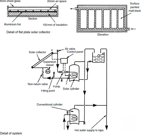
Flat plate – a relatively thin rectangular box with a glass or transluscent cover over a series of small diameter pipes positioned above a black painted absorber plate, insulated on the underside. Installed mainly on south-facing pitched roofs (see next page).
Batch or bread box – a black-painted storage vessel incorporating an insulated tank lined with glass. Located in any position exposed to the sun. Cold water entry is at the base and hot water is drawn from the top. In effect, the bread box functions as a collector, absorber and store of energy in hot water.
Transpired – a south-facing exposed external masonry wall used as an active thermal store. Its performance is enhanced by overlaying the wall with a dark-coloured sheet metal plate collector, perforated to draw in outdoor heated air. This air or the heat energy in the wall can be used to directly pre-heat air conditioning/ventilation air or indirectly across the evaporator of a heat pump (see pages 302–306).
Evacuated glass tube (detailed on page 118).
Overheating – A correctly sized expansion vessel will be adequate for all but extreme situations. However, the effect of the sun is variable and very high water temperatures and pressures can occur in solar collectors. This could result in excessively high domestic stored hot water and possibly system fractures. Some control can be achieved with automatic blinds, but more reliable self-venting controls are required. Building Regulations Part G, Approved Document G3 specifically mentions solar systems and defines safety back-up requirements. See pages 86 and 87 for safety facilities applied to sealed systems and page 98 for thermal stores.
Approximate sizing of solar collector area (see also pages 119 and 120):
Domestic hot water – 1.0 to 2.0m2 per person served.
Swimming pool – 0.05 to 0.10m2 per 1.0m2 pool surface.
Space heating – 15 to 20% of the heated floor area.
Solar Energy – Flat Plate Collector
Solar energy can contribute significantly to hot water requirements. In some countries it is the sole source of energy for hot water. In the UK its efficiency varies with the fickle nature of the weather, but fuel savings of about 40% are possible. For domestic application, the collector should be 4 to 6m2 in area, secured at an angle of 40° to the horizontal and facing south. The solar cylinder capacity of about 200 litres is heated to 60°C. The cylinder and associated pipework must be very well insulated and the solar part of the system should contain a blend of water and non-toxic antifreeze. The pump is switched on when the temperature of water at point X exceeds that at point Y by 2 to 3°C. The solar cylinder and the conventional cylinder may be fitted on the same level, or to save space a combined solar/conventional cylinder can be obtained from specialist suppliers.
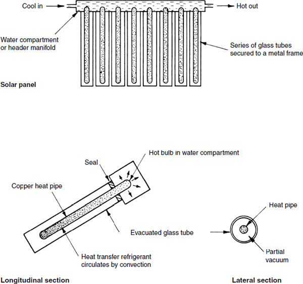
Solar Energy – Evacuated Glass Tube Collector
Although having the general appearance of a panel, the evacuated glass tube collector functions differently from a flat plate collector. The panel is made up of a series of refrigerant charged copper tube elements as heat exchangers or heat pipes contained concentrically within individual vacuum-sealed glass tubes. The advantage is that a refrigerant is more responsive than water, with better performance in low light conditions. The outer glass tubes provide for greater efficiency at high temperatures.
The refrigerant within the inner heat pipes evaporates in response to solar gain. This generates a convection cycle as the hot vapour gives off its heat energy into water circulating through a header pipe compartment or manifold. The cooling vapour condenses into a fluid, returning to the lower part of the heat pipe to continue the cycle.
Solar Energy – Collector Panel Size
The area of a solar collecting panel should not exceed the potential of the system it serves. A relatively large collector area does not necessarily provide greater effect or efficiency. Oversizing can cause an excess of hot water and possibly overheating (heat stagnation). Heating system components are not designed to withstand persistent and excessively high temperatures and pressures. If they are subjected to this, they may malfunction and create safety issues for the end user, particularly with regard to risk of scalding. See Note 2 relating to thermal stores and solar panels on page 98 and the reference to Building Regulation G3.
The basis for sizing a solar system is determined by the daily hot water demand. This can be calculated from data in BS 6700. The BS provides guidance on volumes of water used by appliances. Alternatively, figures can be used from floor area data in the UK government publication, Standard Assessment Procedure for Energy Ratings of Dwellings (SAP). Some other guidance is shown on page 122.

Ref. BS 6700: Design, installation, testing and maintenance of services supplying water for domestic use within buildings and their curtilages. Specification.
Solar Energy – Collector Panel Size
Guidance for sizing a solar panel for domestic hot water –
Estimate the quantity of energy required (Q) in kWh/day.
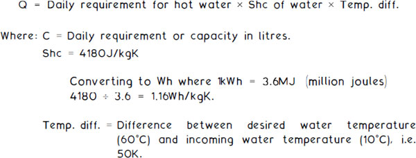
E.g. For a hot water storage facility of 200 litres daily use:

Estimate the size of solar collector panel area (A) in m2.

Where:
No. of days is 365 if the panel is in use all year.
Q is taken from the calculation above.
Solar fraction is the amount of energy provided and effectiveness of the collector relative to the total amount of energy that the installation requires. Zero is where there is no solar facility and 1 or 100% is for all energy from a solar source. 55% is a typical figure for the UK.
Annual solar irradiation – see map on previous page or take an annual estimate from the map on page 678.
Average system efficiency – related to that at the equator, up to 60% in the UK.
E.g. Using a figure of 2.6kWh/day (map on previous page):

Applied to the solar collector panel sizing formula:

Properties of Heat – Hot Water
The heat energy properties of water are fundamental for determining pipe sizes and component dimensions in hot water and heating systems. HEAT is a form of energy, otherwise known as thermal energy.
The standard unit of energy is the joule (J).
1 joule = amount of energy supplied by 1 watt (W) in 1 second (s).
Other units of energy found in older textbooks and product references include:
1 British thermal unit (1Btu) = 1·055kJ
1 calorie (1 cal) = 4·187J
1 kilowatt hour (1kWh) = 3·6MJ
1 therm (1 therm) = 105·5MJ
POWER is a measure of work rate.
Power (W) = heat energy (J) – time in seconds (s)
Thus, 1W = 1 joule/second
TEMPERATURE is measured on a scale between two fixed points. These points are chosen at normal atmospheric pressure to represent water at the melting point of ice as zero, and the boiling point at 100, hence the term centigrade. A point on this scale is known as degrees Celcius (°C). The thermodynamic or absolute scale of temperature is represented in degrees Kelvin (K). Temperature intervals are the same as Celcius, but Kelvin originates at −273·15°C, the point at which no more internal energy can be extracted from a body. Temperature change intervals of 1°C and 1K are the same, except that
thermodynamic temperature (K) = temperature in °C + 273·15:
e.g. 1: |
water at 30°C = 303·15K |
e.g. 2: |
a hot water system with primary flow and return temperatures of 80°C and 70°C respectively, has a temperature differential of 10K. |
SPECIFIC HEAT CAPACITY (Shc) is the amount of heat energy required to raise 1 kilogram (kg) of a substance by 1K.
Some approximate values of Shc (will vary slightly with temperature and pressure):

From the above, it can be seen that it would require over four times as much heat energy to raise 1kg of water 1K, than 1kg of air (4180 + 1010 = 4·14). Conversely, as the Shc of water is relatively high, it is a good medium for storing heat. This is also a reason why hot water plant occupies less space than warm air systems, i.e. pipes are much smaller than air ducts conveying the same amount of energy.
The capacity of hot water storage vessels must be adequate for the building purpose. Exact requirements are difficult to determine, but reasonable estimates are possible. These should include provision for rate of energy consumption (see table below) and the time taken to reheat the water to the required storage temperature (see boiler rating calculation – next page). Many buildings have variable use and inconsistent demands. This often creates an overdesign situation, unless care is taken to establish peak use periods and the system calculations adjusted accordingly. With these building types, non-storage instantaneous fittings may be preferred.
For most buildings the following table can be used as guidance:
Building purpose |
Storage capacity (litres/person) |
Energy consumption (kW/person) |
|---|---|---|
Dwellings: |
||
single bath |
30 |
0·75 |
multi-bath |
45 |
1·00 |
Factory/office |
5 |
0·10 |
Hotels |
35* |
1·00 |
Hostels |
30 |
0·70 |
Hospitals |
35* |
1·00 |
Schools/colleges: |
||
day |
5 |
0·10 |
boarding |
25 |
0·70 |
Sports pavilions |
35 |
1·00 |
* Average figures
E.g. A student hall of residence (hostel) to accommodate 50 persons. Capacity: 50 × 30 = 1500 litres
Energy consumption: 50 × 0·70 = 35kW
The nearest capacity storage vessel can be found in manufacturers catalogues or by reference to BS 1566. For convenience, two or three cylinders of equivalent capacity may be selected.
Boilers are rated in kilowatts, where 1 watt equates to 1 joule of energy per second, i.e. W = J/s. Many manufacturers still use the imperial measure of British thermal units per hour for their boilers. For comparison purposes 1kW equates to 3412Btu/h.
Rating can be expressed in terms of gross or net heat input into the appliance. Values can be calculated by multiplying the fuel flow rate (m3/s) by its calorific value (kJ/m3 or kJ/kg). Input may be gross if the latent heat due to condensation of water is included in the heat transfer from the fuel. Where both values are provided in the appliance manufacturer’s information, an approximate figure for boiler operating efficiency can be obtained, e.g. if a gas boiler has gross and net input values of 30 and 24kW respectively, the efficiency is 24/30 × 100/1 = 80%.
Oil and solid fuel appliances are normally rated by the maximum declared energy output (kW), whereas gas appliances are rated by net heat input rate (kW[net]).
Calculation of boiler power:
![]()
where: |
1 litre of water weighs 1kg |
Shc = specific heat capacity of water, 4·2kJ/kgK | |
K = degrees Kelvin temperature interval | |
Temp. rise = rise in temperature that the boiler will need to increase the existing mixed water temperature (say 30°C) to the required storage temperature (say 60°C). | |
Time in seconds = time the boiler takes to achieve the temperature rise: 1 to 2 hours is typical, use 1·5 hours in this example. |
From the example on the previous page, storage capacity is 1500 litres, i.e. 1500kg of water. Therefore:
![]()
Given that the boiler has an efficiency of 80%, it will be gross input rated:
![]()
Note: The boiler-operating efficiency is the relationship between a unit of fuel energy consumed to produce a unit of heat energy in the appliance hot water. It is not to be compared with the seasonal efficiency of a boiler (SEDBUK), see page 129.
Pipe Sizing – Primary Flow and Return
The water in primary flow and return pipework may circulate by convection. This produces a relatively slow rate of movement of about 0–2m/s, depending on pipe length and location of boiler and cylinder. Modern systems are more efficient, incorporating a circulation pump to create a water velocity of between 0–50 and 3-0m/s. This permits smaller pipe sizes and will provide a faster thermal response.
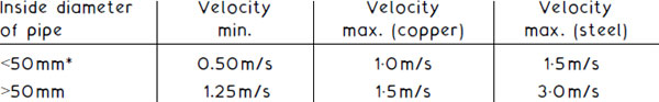
Exceeding these recommendations may lead to excessive system noise and possible pipe erosion.
E.g. using the Copper Development Association design chart shown on the next page, with the boiler rating from the previous example of 43.75kW gross heat input and 35kW net heat input.
![]()
Temperature difference between primary flow (pf) and primary return (pr) in pumped water circuits is usually about 10K, i.e. 80°C – 70°C. With convected circulation the return temperature will be about 60°C.
![]()
On the design chart, coordinating 0.83kg/s with a pumped flow rate of 1m/s indicates a 42 mm inside diameter copper tube (35 mm is just too small).
By comparison, using convected circulation of, say, 0.15m/s and a mass flow rate with a 20K temperature difference of 0·42kg/s, the pipe size would be 76mm.
Water Flow Resistance Through Copper Tube
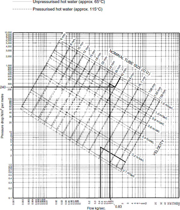
Reproduced with the kind permission of the Copper Development Association.
Circulating Pressures – Gravity Systems
Where gravity or convection circulation of hot water between boiler and emitter is used, guidance on the circulating pressure can be determined by applying standard gravity of 9·80665m/s2 (generally taken as 9·81) to the water density differential between boiler flow and return pipes. Reference to page 82 shows water density values between 0°C and boiling point.
Formula:
![]()
E.g.
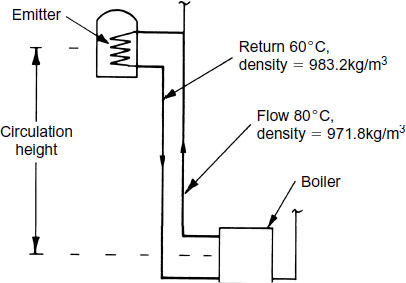
Water density differential = 983·2 – 971·8 = 11·4kg/m3
CP = 9·81m/s2 × 11·4kg/m3 = 111·8, i.e. 112N/m2 per m
If, for purposes of this example, the system output is rated at 8–4 kW, the mass flow rate will be:
![]()
With coordinates of 112N/m2 per metre and 0·1kg/s, the chart on the previous page indicates that a 22 mm outside diameter copper tube could be used for the flow and return pipes. However, this does not allow for the slow circulation velocity, frictional resistance due to fittings and the need for a reasonable heat response time. A more reliable guide compares circulation velocity typically about 0·15 m/s with the calculated 0·1kg/s. On the chart this indicates that a 35mm pipe would be more appropriate.
A less arbitrary determination of fluid flow criteria can be obtained from the reference data in Guide C produced by the CIBSE.
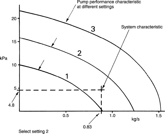
Circulatory pumps produce minimal pressure in the primary flow and return, but the flow rate is considerably enhanced. The pressure can be ascertained from design charts as a pressure drop in N/m2 per metre or pascals per metre. 1N/m2 equates to 1 pascal (Pa).
From the design chart, circulation in a 42mm copper tube at 1m/s produces a pressure drop of 240Pa per metre. An estimate of the primary flow and return effective pipe length (see page 71) is required to establish the total resistance that the pump must overcome. For example, if the effective pipe length is 20m:
![]()
Therefore the pump specification would be 0·83kg/s at 4·8kPa.
Manufacturers’ catalogues can be consulted to select a suitable pump. To provide for flexibility in installation, a degree of variable performance is incorporated into each model of pump. This range of characteristics can be applied by several different control settings, as shown in the following graphic.
Pump performance chart:
Legionnaires ’ Disease in Hot Water Systems
Bacterial growths which cause Legionnaires disease develop in warm, moist, natural conditions such as swamps. They have adapted to living in the built environment in the artificial atmosphere of air-conditioning and hot water systems. A large number of outbreaks of the disease have occurred, with some people suffering a prolonged illness similar to pneumonia. The elderly are particularly vulnerable and many have died, hence the name of the illness which was attributed to a group of retired legionnaires who were infected while attending a reunion in Philadelphia, USA in 1976. Numerous other outbreaks and subsequent deaths have led to strict maintenance and installation controls of services installations. This has been effected by the Health and Safety Executive under the Health and Safety at Work, etc. Act and the Workplace (Health, Safety and Welfare) Regulations. The following measures are recommended for use with hot water systems:
Stored hot water temperature 60 to 65°C throughout the storage vessel.
Routine maintenance involving heating the water to 70°C as a precaution.
Changing the design of cylinders and calorifiers with concave bases. These are suspect, as the lower recesses could provide areas of reduced water temperature with little or no movement.
Connections to storage vessels should encourage through movement of water.
Pipework ‘dead-legs’ to be minimal.
All pipework to be insulated to reduce water temperature losses.
Where secondary circulation is required, supplementary trace element heating tape should be applied to maintain a minimum water temperature of 50°C.
Showers with recessed/concave outlet roses to be avoided. Other designs to have a self-draining facility to avoid inhalation of contaminated moisture droplets.
Spray taps – similar provision to 8.
Note: Cold water should be kept below 20°C.
SEDBUK is the acronym for Seasonal Efficiency of Domestic Boilers in the United Kingdom. It has developed under the government’s Energy Efficiency Best Practice Programme to provide a manufacturers’ data base which represents the efficiency of gas- and oil-fired domestic boilers sold in the UK. See website: www.boilers.org.uk, or www.sedbuk.com. This voluntary site is updated monthly and contains over 75% of new and existing products.
SEDBUK must not be confused with the operating efficiencies which are sometimes quoted in manufacturers’ literature. These compare gross and net heat input values – see page 123. SEDBUK is the average annual in-use efficiency achieved in typical domestic conditions. The principal parameters included in the SEDBUK calculation are:
type of boiler
fuel ignition system
internal store size
type/grade of fuel
summer and winter seasonal efficiency
typical patterns of usage – daily, weekly, etc.
climatic variations.
Quoted SEDBUK figures are based on standard laboratory tests from manufacturers, certified by an independent Notified Body which is accredited for boiler testing to European Standards.
Efficiency bands:
Band |
SEDBUK range (%) |
|---|---|
A |
90–100 |
B |
86–90 |
C |
82–86 |
D |
78–82 |
E |
74–78 |
F |
70–74 |
G |
<70 |
See next page for acceptable band values for different fuels and installations.
Note: Efficiency bands are due to be withdrawn, to be replaced by an Energy-using Products Directive (EuP). The EuP will provide an energy efficiency label similar to that used on domestic appliances. For further guidance on this see page 198.
Building Regulations, Approved Document L1: Conservation of fuel and power in dwellings, requires reasonable boiler efficiency for wet heating installations in new dwellings and for replacement equipment in existing dwellings. The following values are acceptable:
Fuel system and boiler type |
Min. SEDBUK value (%) |
|---|---|
Gas |
90 |
Gas range cooker/boiler |
75 |
Oil |
90 |
Oil combination boiler |
86 |
Oil range cooker/boiler |
80 |
Solid fuel |
See HETAS certification |
The SEDBUK database is an essential reference when calculating part of the government’s Standard Assessment Procedure for Energy Rating of Dwellings (SAP rating). Additional factors to be considered are: ventilation, heat losses through the fabric (U values) and solar gains. To comply with the Building Regulations, builders are required to submit energy-rating calculations to the local building control authority. This data is also available for prospective house buyers and tenants for comparison purposes when assessing anticipated annual fuel costs for hot water and heating. SAP values vary from 1 to 100, with 80 considered the minimum expectation of new dwellings.
Recognised organisations for accrediting ‘competent persons’ as installers of domestic hot water and central heating systems:
Gas – Capita Group ‘Gas Safe Register’.
Oil – Oil Firing Technical Association for the Petroleum Industry (OFTEC).
Solid fuel – Heating Equipment Testing and Approval Scheme (HETAS).
Refs. Building Regulations, Approved Document L1: Conservation of fuel and power in dwellings, 2010.
The Government’s Standard Assessment Procedure for Energy Rating of Dwellings, 2009.
(Both published by The Stationery Office)
Domestic Building Services Compliance Guide. (NBS-RIBA Enterprises Ltd), 2010.
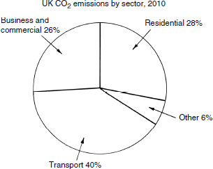
The progressive Building Regulations of 1990, 1995, 2002 and 2010 have made substantial improvements to standards of energy efficiency. Since 2002, several more initiatives have been applied to the installation and use of fuel-consuming appliances and attention to details of construction. Buildings have been specifically identified as the source of about 50% of all atmospheric carbon emissions. Half of this is attributed to emissions from domestic hot water and heating equipment.
The initial objectives are to:
Reduce the carbon dioxide (CO2) emissions from boilers by 80% relative to 1990 measures before 2050; 15% of energy generated from renewable sources by 2020.
Maintain the reliability of fuel energy supplies and resources.
Promote a competitive energy market in order to encourage sustainable economic growth and productivity.
Ensure that all homes are adequately and affordably heated.
Effects:
Domestic boilers – new and replacement appliances of SEDBUK rating A only, i.e. high-efficiency condensing boilers.
Insulation standards for new and refurbished buildings improved, e.g. replacement windows and reduced ‘U’ values.
Regular inspection and maintenance of air-conditioning systems.
Measures to prevent overheating by solar gain.
Installation of energy recovery systems, e.g. MVHR and heat pumps.
Restricted use of inefficient appliances, e.g. gas decorative-effect fires.
Insulation of hot and chilled water pipework and sealing of ductwork joints to prevent air leakage.
Use of high-efficacy electric lamps and power rating limitations on external lighting.
Calculation of carbon emission limits from dwellings, re. SAP ratings. For other buildings measures required to show improvements, such as renewable energy use, solar systems and CHP.
Reduced air leakage through the building envelope, max. 10m3/hour/m2 at 50Pa.
Ref. The Code for sustainable Homes. DCLG.
Galvanic or Electrolytic Action
Electrolysis – the corrosion or decomposition of different metals in the presence of water. Three criteria exist which will encourage corrosion:
Neutral or acidic water, pH value ≤7
Warm or hot water
Metals widely apart on the electrochemical or galvanic series.
Electrochemical series for metals used in plumbing and hot water services:
Protected end (cathode) |
Stainless steel |
Copper | |
Gunmetal and bronze | |
Tin | |
Lead | |
Steel | |
Cast iron | |
Aluminium | |
Zinc (galvanising) | |
Corroded end (anode) |
Magnesium |
Water functions as an electrolyte, i.e. a solution which conducts an electric current between a cathode and anode of dissimilar metals. Therefore, in water services systems materials must be compatible, otherwise decomposition of pipework and equipment will occur. For example, galvanised steel and copper pipes should never be used together, particularly in hot water installations.
Plumbo-solvency – term used to describe the breakdown of lead pipes conveying water with ‘soft’ characteristics. This should not be a problem, as for health reasons lead is no longer acceptable as a water services material. However, exposed lead flashings could be affected in areas of ‘soft’ rainwater.
Cupro-solvency – term used to describe the breakdown of copper pipes where soft water contains dissolved carbon dioxide. This type of water is generally associated with private wells and springs.
Dezincification – this affects brass pipe fittings and valves. Brass is an alloy of copper and zinc (50:50). Electrolytic reaction between the two metals, particularly in high chloride waters, causes corrosion of the zinc. This leaves the fitting unchanged in appearance, but with no strength and possibly porous. Installations in areas known to be prone to this problem should be specified with gunmetal fittings, an alloy of copper, tin and zinc (85:10:5).
Anodic protection – before the introduction of plastic storage cisterns it was common practice to fit a sacrificial anode of magnesium into galvanised cold water storage cisterns if copper pipes were used. As magnesium is below zinc in the electrochemical series, the magnesium dissolves away instead of the galvanising. Sacrificial anodes are fitted as a precautionary measure to the inside of copper hot water storage cylinders.
Water Treatment – System Flushing
As part of the commissioning and testing process (see page 202), new water services to include every length of pipe, cistern, hot water storage cylinder and all connected components should be flushed through with wholesome water. This process is not to be regarded as a substitute for care and cleanliness during installation.
Cisterns in particular should receive special attention. Any debris or deleterious matter must be removed before a cistern and associated system is filled. Failure to undertake this simple check may be the cause of system blockages, pipework corrosion, contamination of the supply, reduced system efficiency and reduced effectiveness of any water treatments. For installations larger than that required for single-family private dwellings, cisterns should be filled with chlorinated water at a dosage of 50 parts chlorine to 1 million parts water (50mg/litre). Terminal valves and taps are opened to ensure the presence of chlorine by smell, then closed and the system allowed to stand for at least one hour. After this time the chemical smell should again be present at opened terminals (at least 30ppm by measure). If not, the procedure is repeated. Thereafter, the system is flushed with wholesome water to remove any remaining chemical.
Fluxes used with soldered capillary joints on copper tube will in general dissolve in water, but large deposits can become water repellent and may attract a buildup of surface deposits. In practice there is no need for an excess of flux to be applied.
Filling and draining from the lowest point of an installation is insufficient to ensure complete cleansing. All terminal connections, particularly those at the end of long horizontal runs and ‘dead-legs’, should be opened and flushed through. Where work has been completed on a building or it is left unoccupied, pipe systems should not be charged with water that could become stagnant. To reduce the possibility of pipework corrosion and water quality issues, unused systems should be flushed regularly, i.e. at least twice during a week.
Ref. Water Supply (Water Fittings) Regulations, Schedule 2, Paragraph 13.
Water Treatment – System Disinfection
Disinfection – the process of sanitising water by deactivating any living bacterial and micro-organisms in hot or cold water systems. Adding approved chemicals to the system water is the most common method. After testing and flushing, all new installations should be disinfected. An exception is small works such as private dwellings occupied by only one single family. Disinfection also applies to underground supplies.
Procedures:
Off-line (chemical) – the use of either sodium hypochlorite or stabilised chlorine dioxide as oxidising disinfectants to produce free residual chlorine. Application as described on the previous page. Bromine and ozone oxidising disinfectants are alternative additives. Precautions during use include system backflow prevention, personal protective equipment and terminals/outlets to be marked DISINFECTION IN PROGRESS – DO NOT USE. Disposal facilities to be agreed with the water authority and the Environment Agency.
Off-line (thermal) – this is supplementary to disinfecting supply cisterns as described on the previous page. The process is otherwise known as pasteurisation and it requires raising the whole system water temperature to between 60 and 70°C and maintaining this for at least one hour.
On-line (chemical) – a routine or continuous dosing process (manual or automatic) using chlorine or chlorine dioxide. Where used with a drinking water supply, will require specific approval from the water authority.
On-line (electrical) – use of an electric water conditioner that releases copper and silver ions through electrodes in the supply pipe.
On-line (thermal) – see pages 128 and 400.
Ref. BS 6700: Design, installation, testing and maintenance of services supplying water for domestic use within buildings and their curtilages. Specification.
Water Treatment – Domestic Hot Water Installations
Bacteria – the most common bacteria in water systems is Pseudomonas bacteria. It occurs where there is lack of water circulation or stagnation in discontinuous lengths of pipes and storage vessels. The latter is typical of expansion and feed cisterns in indirect hot water and central heating systems. High ambient temperatures between 20 and 40°C and poorly ventilated roof spaces or compartments are ideal for its development. First indications are usually its highly putrid odour. Inspection usually reveals a brown, slimy film lining the water surface and storage cistern. Eradication is by flushing and disinfection with biocides in solution.
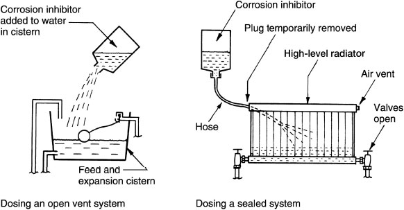
Corrosion inhibitors – see also page 203. Boiler and associated equipment will only operate effectively and efficiently if water in the system is maintained clean and free of impurities. The minimal buildup of scale or magnetite sludge will significantly reduce boiler efficiency and increase its contribution to carbon emissions.
New systems should be flushed to remove debris such as metal filings, flux and loose solder deposits. Filling is with clean water and the manufacturer’s recommended dose of corrosion inhibitor, as shown in the illustrations. Following maintenance, repair or modification, existing systems should be treated similarly.
Proprietary corrosion inhibitors may be compounds of sodium silicate, benzoate, nitrite and chromate. Sodium pentachlorophenate is a bacteriacide or biocide which can be used to prevent the accumulation of hydrogen gas in radiators.
Refs. BS 7593: Code of practice for treatment of water in domestic hot water central heating systems.
Domestic Building Services Compliance Guide.
Building Regulations, AD L1A and L1B: Conservation of fuel and power.