
Air Conditioning – Principles and Application
Fan-coil (Air/Water) Unit and Induction Diffuser
Refrigerant System Characteristics
Packaged Air-Conditioning Systems
Psychrometrics – Processes and Applications
Air conditioning is achieved by developing the principles of moving air in ducted ventilation systems to include a number of physical and scientific processes which enhance the air quality. The objective is to provide and maintain internal air conditions at a predetermined state, regardless of the time of year, the season and the external atmospheric environment. For buildings with human occupancy, the design specification is likely to include an internal air temperature of 19–23°C and relative humidity between 40 and 60%.
The following is a glossary of some of the terminology used in air-conditioning design:
Dew point – temperature at which the air is saturated (100% RH) and further cooling manifests in condensation from water in the air.
Dry bulb temperature – temperature shown by a dry sensing element such as mercury in a glass tube thermometer (°C db).
Enthalpy – total heat energy, i.e. sensible heat + latent heat. Specific enthalpy (kJ/kg dry air).
Entropy – measure of total heat energy in a refrigerant for every degree of temperature (kJ/kg°C).
Latent heat – heat energy added or removed as a substance changes state, while temperature remains constant, e.g. water changing to steam at 100°C and atmospheric pressure (W).
Moisture content – amount of moisture present in a unit mass of air (kg/kg dry air).
Percentage saturation – ratio of the amount of moisture in the air compared with the moisture content of saturated air at the same dry bulb temperature. Almost the same as RH and often used in place of it.
Relative humidity (RH) – ratio of water contained in air at a given dry bulb temperature, as a percentage of the maximum amount of water that could be held in air at that temperature.
Saturated air – air at 100% RH.
Sensible heat – heat energy which causes the temperature of a substance to change without changing its state (W).
Specific volume – quantity of air per unit mass (m3 /kg).
Wet bulb temperature – depressed temperature measured on mercury in a glass thermometer with the sensing bulb kept wet by saturated muslin (°C wb).
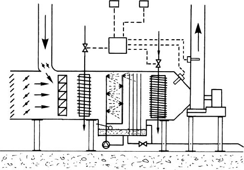
This system is used where the air condition can be the same throughout the various parts of a building. It is also known as an allair system and may be categorised as low velocity for use in buildings with large open spaces, e.g. supermarkets, theatres, factories, assembly halls, etc. A variation could incorporate a heating and cooling element in sub-branch ductwork to smaller rooms such as offices. Very large and high-rise buildings will require a high velocity and high pressure to overcome the resistances to air flow in long lengths of ductwork. Noise from the air velocity and pressure can be reduced just before the point of discharge, by incorporating an acoustic plenum chamber with low-velocity sub-ducts conveying air to room diffusers.
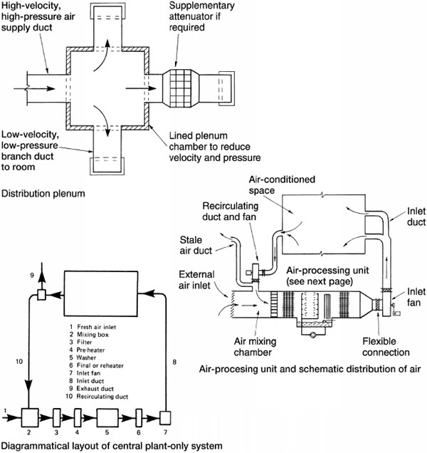
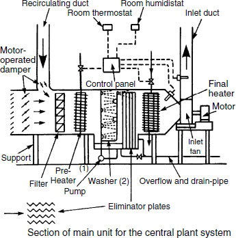
Operation of the main air-processing or air-handling unit:
Fresh air enters through a louvred inlet and mixes with the recirculated air. Maximum 75% recirculated to minimum 25% fresh air.
The air is filtered to remove any suspended dust and dirt particles.
In winter the air is pre-heated before passing through a humidifier. A spray wash humidifier may be used to cool the air up to dew point temperature. If a steam humidifier is used the air will gain slightly in temperature.
In summer the air can be cooled by a chilled water coil or a direct expansion coil. The latter is the evaporator coil in a refrigeration cycle. Condensation of the air will begin, until at saturation level the air dehumidifies and reduces in temperature. Spray washing will also dehumidify the air.
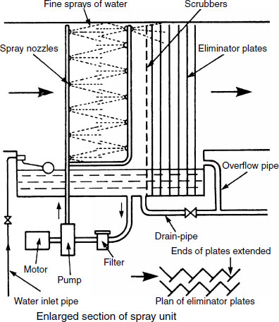
Air washers have zigzag eliminator plates which remove drops of water and any dirt that may have escaped from the filter.
The final heater or reheater is used to adjust the supply air temperature and relative humidity before delivery through a system of insulated ductwork.
Notes:
Pre-heater coil may be used with chilled water as a cooler in the summer months, but two separate coils are usually fitted.
Steam humidifiers are the preferred replacement for spray– wash humidifiers. The high-temperature steam kills any bacteria.
Depending on the state of the air on entering a spray washer, it can be humidified or dehumidified. Humidification in the presence of moisture is understandable, but dehumidification is less easy to comprehend. It occurs when the spray is at a lower temperature than the air and the dew point of the air. In this condition the vapour pressure of the spray will be less than that of moisture in the air and some moisture from the air will transfer into the spray water. Hence, dehumidification.
Washers also remove some of the suspended dirt. Spray water pressure is usually between 200 and 300kPa. Air velocity through the washer is between 2 and 2·5m/s. Spray washers must be cleaned periodically and treated to neutralise any bacteria which could be living in the water. Water quality must also be monitored and findings documented. With numerous outbreaks of Legionnaires ‘disease originating from air- conditioning systems, the Health and Safety Executive have identified these spray washers as a possible health risk.
Contemporary air-processing units may incorporate steam injection humidifiers, but unlike washers, these should not be located immediately after the cooler coil. Here, the air will be close to saturation or even saturated (100% RH) and unable to accept further moisture. Therefore dry saturated steam at over 200°C is better injected into the air close to its final discharge.
The VAV system has a central air-processing unit to produce air at a specified temperature and relative humidity. The conditioned air from the main unit is conveyed in ductwork to ceiling diffusers which incorporate thermostatically controlled actuators. These can change the air volume to suit each room load. In a large room, several of these VAV ceiling units may be controlled by one room thermostat. Several rooms/zones may have separate thermostats to control the air flow to each room. The inlet fan may have variable pitched impellers operated by compressed air. A pressure switch controls the pitch angle. Air distribution is usually medium to high velocity. The air temperature in each zone can be varied with the heat energy in the delivery air volume, but the system is only suitable for buildings having a fairly evenly distributed cooling load.
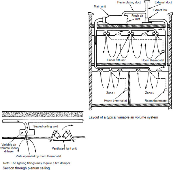
Note: The lighting fittings may require a fire damper Section through plenum ceiling
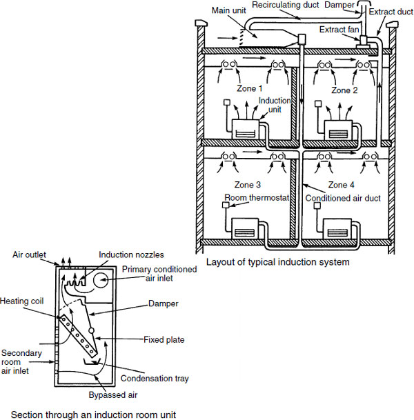
Perimeter induction units – usually located under windows – blend primary air from the air-processing unit with secondary air from within the room. The high-velocity processed air delivery is induced into the unit through restrictive nozzles. This creates a negative pressure in its wake, drawing in the room secondary air for mixing and discharge. A damper regulates the volume of room air passing through a thermostatically controlled heating coil.
These coils may be used with chilled water as cooling coils in the summer months. If heating only is used, the system is known as the ‘two-pipe induction system’ With the additional two pipes for cooling water, the system is known as the ‘four-pipe change-over induction system’. The latter system gives excellent control of the air temperature in various zones but is very capital intensive, and therefore expensive to install.
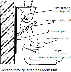
Fan-coil (Air/Water) Unit and Induction Diffuser
Fan-coil unit – an alternative discharge unit for application to the induction system shown on the previous page. Instead of nozzle injection of air, a low-powered fan is used to disperse a mixture of primary and secondary air after reheating or cooling from an energy exchanger within the unit.
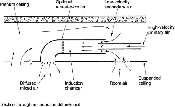
Induction diffuser – another alternative which also uses a blend of recirculated room air with primary air. These locate at the end of branch ductwork and combine a diffuser with a simple primary and secondary air mixing chamber. The high-velocity primary air mixes with low-velocity secondary air drawn into a plenum ceiling from the room below. Light fitting extract grilles may be used to some advantage in this situation.
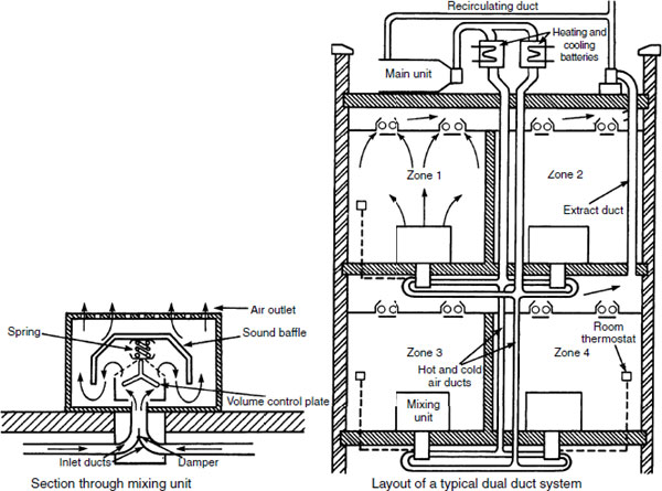
The dual duct system is another means of providing varying air temperatures to different rooms in the same building. There is no water circulation to peripheral discharge units with terminal reheaters or coolers. This simplifies the plumbing installation as heating and cooling elements for each duct are located in the plant room. However, the system is space consuming and adequate provision must be made in suspended ceilings or raised flooring to accommodate both distribution ducts. The system is most energy economic when heating and cooling elements operate individually. For some of the year this will not be practical and simultaneous delivery of cold and hot air is provided for blending at the point of discharge.
Delivery is at high velocity with hot and cold air regulated by a damper connected to a room thermostat. A control plate in the mixing unit maintains constant air volume. As with all systems of air conditioning, fire dampers are required where the ductwork passes through compartment walls and floors.
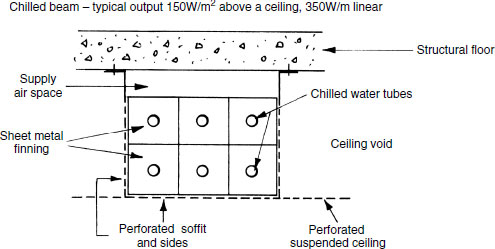
Chilled beams are usually formed as a bank of finned tubing, arranged in a square or rectangular profile. The tubing conveys chilled water and when encased and secured to the underside of a structural floor, the unit resembles a beam. An outer casing of sheet metal can be used to enclose the coiled pipes and this may be perforated to encourage convection through the bank of finned tubing. A passive cooling effect is by natural convection, but active cooling can be achieved by using a fan-driven primary air supply. To conceal the installation, the underside of the box may be finished flush with a perforated suspended ceiling.
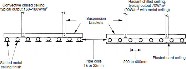
Chilled ceilings were originally devised with chilled water pipes embedded within the underside of a concrete floor slab. The nominal increase in slab depth is justified by no visual intrusion of pipework. This form of radiant cooling has the disadvantage of creating a high thermal mass in the concrete slab, which is slow to respond to thermostatic control. These installations can also produce ‘indoor rain’ or condensation on the radiant underside of the slab. To prevent the ceiling from running wet, a suspended variation is preferred, with the option of an auxiliary or fan-driven primary air supply through perforations in the ceiling. These perforations will also increase the convective effect.
Cooling Systems – Refrigeration
Refrigeration systems are used to:
Cool water for circulation through chiller coils. Brine may be used as a more efficient alternative to water.
Directly chill air by suspending the cold evaporator coil in the air stream. When used in this way, the energy exchanger is known as a direct expansion (DX) coil.
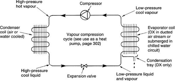
The system most suited to air conditioning is the vapour compression cycle. It is a sealed pipe system containing refrigerant, compressor, condenser coil, expansion valve and evaporator coil, i.e. all the basic components of a domestic fridge.
Refrigerants are very volatile and boil at extremely low temperatures of −30 to −40°C. Some are capable of contributing to depletion of the ozone layer when released into the atmosphere. Dichlorodifluoromethane (R12), known as CFC, was used in many systems, but is now banned. Chlorodifluoromethane (R22), known as HCFC, is less ozone depleting. It is still used, while manufacturers research more environmentally friendly alternatives.
The refrigeration compression and evaporation cycle effects a change of temperature and state in the refrigerant, from liquid to gas and vice versa. Saturation pressure and temperature increase to emit heat at the condenser as heat energy is absorbed by the evaporator. As the liquid refrigerant changes to a gas through the expansion valve, it absorbs considerably more heat than during simple temperature change. This is known as the latent heat of vaporisation.
Various types of refrigerant gas compressor power units can be used for chilling water in air-conditioning systems. Three are classified as positive displacement and the other dynamic.
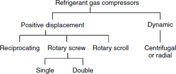
Reciprocating – contains several cylinders (up to 16) in which pistons compress an intake of gas before discharge as superheated vapour. Usually belt driven from an external electric motor. Up to 600kW of refrigeration capacity.
Rotary screw – single or double. A screw cut rotor, or more effectively two meshing screw cut rotors interacting by rotation in opposing directions to contain, reduce and compress the volume of refrigerant. Single 15 to 4500kW and double 120kW to 2MW.
Scroll – contains two spirals or interleaved scrolls, one stationary and the other rotating about it within a cylinder. The effect is to create reducing pockets and higher pressures that compress the refrigerant as it discharges through a restricted port. From 3 to 50kW.
Centrifugal – an aerodynamic lift compressor that raises pressure on the refrigerant by velocity or dynamic energy. Contains rotating impellors with aerofoil vanes, often gear driven to attain the necessary velocity. 300kW to 3MW, greater output possible if multi-staged.
Domestic fridge compressors have an electric motor of about 100W rating within the compressor housing. They may be either:
Reciprocating — rotary motion changing to reciprocating through a crank and connecting rod to a piston.
Rotary motor with blades attached directly to the shaft.
Properties – ideally, the following thermodynamic qualities:
Low boiling point.
Moderate density when liquid.
High density in a gaseous state.
High latent heat of vapourisation/evaporation.
Easily liquified by compression.
Chemically non-reactive.
Safe environmentally, non-corrosive, non-toxic and non-flammable.
Natural refrigerants –
Water (R718) – Inexpensive, readily available, non-toxic with no disposal problems. Requires a high vacuum to enable the water to boil at a low temperature of about 7°C. Equipment costs and size necessary to maintain a high vacuum limit its viability.
Air (R729) – Readily available and free of environmental contamination issues. Requires extremely high pressures to liquefy, limiting its application to large and expensive plant.
Carbon dioxide (R744) – Requires a fairly high power pressure input that limits its use to large-scale equipment. As a gas it is heavy, colourless, odourless, non-flammable and harmless in small quantities. In concentrations exceeding 5% it is toxic.
Ammonia (R717) – A highly efficient, inexpensive refrigerant that has been used in industrial and some domestic appliances since the late nineteenth century. Its energy efficiency is offset by high toxicity, irritation of the skin and potential for explosion.
Hydrocarbons (Propane R290 and Iso-butane R600a) – similar refrigerant properties to HCFC (R22) [see next page] with no ozone depletion potential and very low impact on global warming. Highly inflammable which limits its use.
R Numbering – a classification that identifies the molecular structure. Ninety is added to the number to give three digits representing the number of carbon, hydrogen and fluorine atoms, respectively.
E.g. Propane (R290) 290 + 90 = 380
i.e. 3 carbon, 8 hydrogen and 0 fluorine atoms.
A suffix a, b or c indicates progressively unsymmetric isomers.
Chlorofluorocarbon (CFC) – in the latter part of the nineteenth century and early part of the twentieth century, refrigerants in common use were ammonia (R717), methyl chloride (R40) and sulphur dioxide (R764). Leakage of these toxic and corrosive gases had very harmful even deadly effects, promoting research into the development and manufacture of less aggressive man-made chemical blends. The result was dichlorodifluoromethane (R12), marketed from 1930 under several trade names, one of the better known being Freon. This chlorine, fluorine and carbon (CFC) blend was colourless, odourless, non-flammable and non-toxic. For several decades it was used in domestic appliances, commercial and automotive applications until the 1980s when it was found that CFC leakage contributed significantly to depletion of the ozone layer and global warming. These gases were then phased out of production and are now completely banned.
Hydrochlorofluorocarbon (HCFC) – refrigerant is a subclassification of CFC that has the addition of hydrogen. HCFCs have less impact on ozone depletion and global warming than CFCs due to a lower chlorine content. However, there is some environmental effect, so HCFCs are only regarded as transitional CFC replacements before being completely phased out in 2015. The HCFC Chlorodifluoromethane (R22) has been widely used in domestic fridges and freezers as well as commercial heat pump, air-conditioning and refrigeration equipment.
Replacement ozone-friendly refrigerants known as zero depletion potential (0DPs) with very low contribution to global warming have no chlorine content. These are known as hydrofluorocarbons (HFCs) and include the following:
Tetrafluoroethane |
(R134a) |
|
Trade names – Genetron 134a and Suva 134a. |
||
Azeotropic blends: |
(R407c) |
[23% R32, 25% R125, 52% R134a] |
Trade names – Klea and AC 9000. |
||
(R410a) |
[50% R32, 50% R125] |
|
Trade names Puron and Suva 9100. |
||
(R417a) |
[50% R134a, 46.5% R125, 3.5% R600] |
|
Trade name – Isceon 59. |
||
The following is a small extract from hundreds of refrigerants. It is for comparison purposes and samples some of the refrigerants used in the past and some in current use.
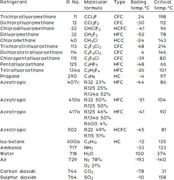
Notes:
Azeotropic – a mix of two or more liquids.
Chloromethane – historically known as methylchloride.
Critical temp. – Temperature above which it cannot exist as a liquid.
Refrigerant System Characteristics
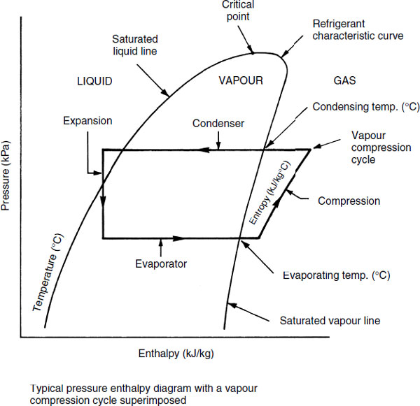
Pressure enthalpy diagram – graphical representation of a refrigerant showing its total heat content (sensible + latent heat = enthalpy) during liquid, vapour and gaseous states at a given pressure.
Detailed charts are produced by refrigerant manufacturers such as ICI Plc and professional organisations such as the Chartered Institution of Building Services Engineers. The diagram below indicates the outline of these charts. The principal curved line divides the three states of a refrigerant during pressure, temperature and energy change.
For design purposes, the system operating characteristics can be superimposed on the chart to illustrate changes that occur during the refrigeration cycle. By comparing the system vapour compression cycle on various charts, it is possible to determine the most suitable refrigerant for the purpose.
Cooling Systems – Air-cooled Condenser
Efficient operation of refrigeration systems depends to a large extent on maintaining condenser temperature at an optimum level. This is necessary for correct reaction of the refrigerant. The cooling medium can be water or air. Water is more effective, but for practical purposes and health issues (see page 291), air cooling is becoming more widely used.
The condenser coil on a domestic fridge is suspended at the back of the unit and exposed to ambient air to cool. This same principle can be applied to small packaged and portable air-conditioning units, possibly with the addition of a fan to enhance the cooling effect. Larger-scale air-conditioning installations have several high-powered fans to cool the condensers. These fans can be mounted horizontally or vertically to draw high-velocity air through the condenser coils.

Cooling Systems – Water-cooled (Natural Draught) Condenser
Natural draught water cooling can take many forms. The simplest and most inexpensive is a pond. Cooled water is drawn from one end and warm return water pumped into the other. Spray ponds are more efficient and may incorporate ornamental fountains as part of the process. Both have a tendency to accumulate debris and will require regular attention.
More common are evaporative atmospheric cooling towers. These are usually located on the building roof or within the roof structure plant room. Wall construction is louvred to permit cross-flow of air. Internally the tower is either hollow or plastic baffled to increase the wetted contact area. Warm water from cooling the condenser is discharged through a bank of high-level sprays to cool as it descends through the air draught. It is then recirculated to the condenser.

Cooling Systems – Water-cooled (Mechanical Draught) Condenser
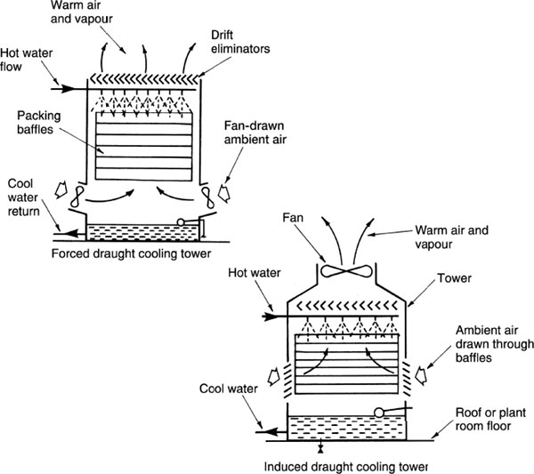
Mechanical fan draught cooling provides absolute control over the air supply, operating independently of fickle weather and wind direction. Fan draught cooling towers are of two types:
Forced draught – similar in construction and operating principle to the natural draught tower, but with one or more low-level fans to force air through the tower.
Induced draught – a large high-level fan draws or induces air flow through the tower. The relatively large single fan is more economic in use and less likely to generate system noise and vibration.
Note: All water-cooling towers have become notorious as potential breeding areas for bacteria such as that associated with Legionnaires’ disease. Therefore, towers must be maintained regularly and the water treated with a biocide, with regard to Workplace (Health, Safety and Welfare) Regulations 1992.
Packaged Air-conditioning Systems
Packaged air-conditioning systems are factory-manufactured units, delivered to site for direct installation. They contain a vapour compression cycle refrigeration system, using the evaporator for cooling and the condenser for heating, with fan delivery of the processed air. They are available in a wide range of power capacity, fan output, refrigeration and heating load for adaptation to various building types and situations.
Small- to medium-sized buildings are best suited to these systems as it would be too costly and impractical to provide numerous units for use in multi-roomed large buildings. The smallest units (1–3kW) are portable and free-standing, simply plugging into an electrical wall socket. Larger, fixed units (generally 10–60kW, but available up to 300kW) can be unsightly and difficult to accommodate. These may be located in a store-room and have short ductwork extensions to adjacent rooms.
Packages contain all the processes of conventional air-handling units, with the exception of a steam or water humidifier. Humidification is achieved with condensation from the direct expansion (DX) refrigeration coil suspended in the air intake.
For summer use, the cold (DX) coil cools incoming and recirculated air. The hot condenser coil is fan cooled externally. For winter use, the refrigeration cycle is reversed by a change-over valve to become a heat pump – see page 302. Now the cold incoming air is warmed or pre-heated through the hot condenser coil and may be further heated by an electric element or hot water coil at the point of discharge.
System types:
Self-contained (single) package.
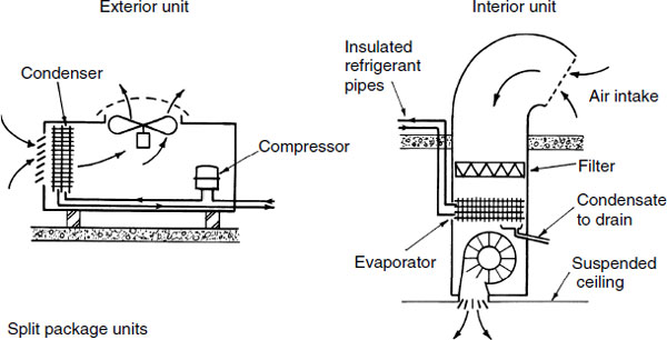
Split (double) package.
Self-contained (single) package – suitable for relatively small rooms, e.g. shops, restaurants and classrooms. May be free-standing or attached to the structure.
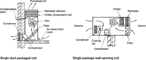
Split (double) package – two separate units. One contains fan, filter, evaporator and expansion valve for interior location. The other contains condenser, fan and compressor for external location. The two link by refrigeration pipework. This has the advantage that one external unit can serve several interior units.
Psychrometry – the science of moist air conditions, i.e. the characteristics of mixed air and water vapour. This can be calculated or design manuals consulted for tabulated information. Graphical psychrometric details are also available for simplified presentation of data. The chart outlined below is based on the calculated interrelationship of air properties at varying temperatures and conditions. In more detailed format, reasonably accurate design calculations can be applied. These are based on the processes shown plotted on the next page.
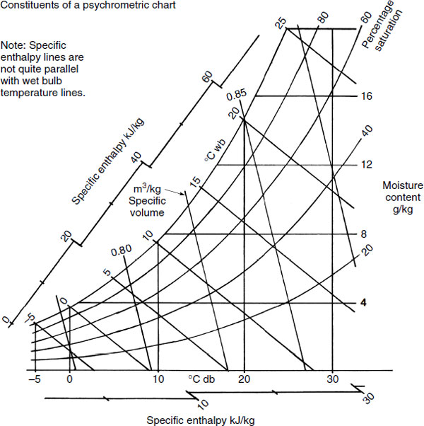
The above diagram represents only the outline structure of a psychrometric chart. For accurate applications and calculations, detailed charts are available from the publications section of the Chartered Institution of Building Services Engineers. Contact, www.cibse.org.
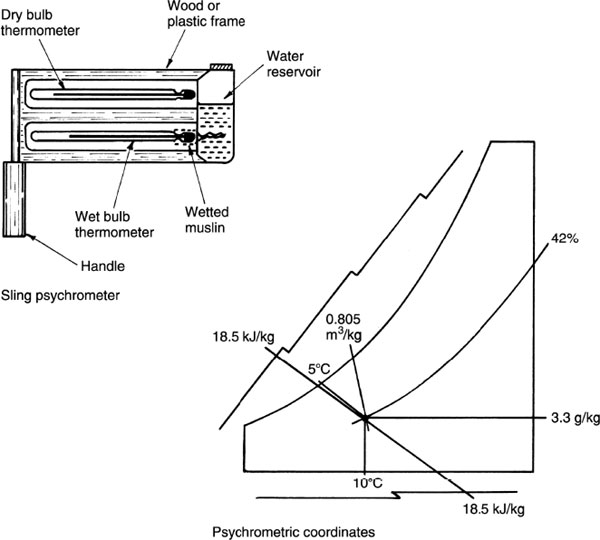
To locate a representative air condition on the psychrometric chart, two properties of the air must be known. The easiest coordinates to obtain are the dry and wet bulb temperatures. These can be measured from a sling psychrometer, also known as a whirling or sling hygrometer. Two mercury-in-glass thermometers are mounted in a frame for rotation about the handle axis. One thermometer bulb has a wetted muslin wick. After rotation, the wet bulb temperature will be lower than the dry bulb due to the evaporation effect of moisture from the muslin. The extent of evaporation will depend on the moisture content of the air.
For example, a sling psychrometer indicates 10°C db and 5°C wb temperatures. From the chart the following can be determined:
Percentage saturation = 42%
Moisture content = 3·3g/kg dry air
Specific volume = 0·805m3/kg
Specific enthalpy = 18·5kJ/kg
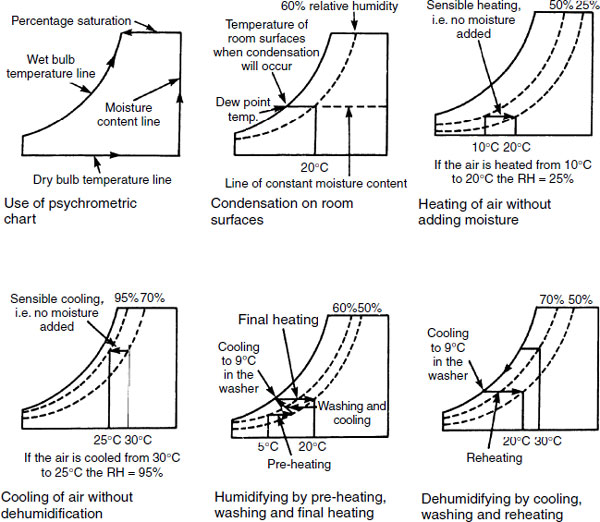
Treatment of air is based on heating, cooling, humidification and dehumidification. These processes can be represented by lines drawn on the psychrometric chart.
Heating (sensible) is depicted by a horizontal line drawn left to right. Dry bulb temperature increases with no change in moisture content, but there is a reduction in percentage saturation.
Heating (latent) is the effect of steam humidification and is represented by a rising vertical line. Dry bulb temperature remains the same, moisture content and percentage saturation increase.
Cooling (sensible) is depicted by a horizontal line drawn right to left. Dry bulb temperature decreases with no change in moisture content. Cooling by water spray humidifier is represented by an incline following the wet bulb temperature line. This is known as adiabatic humidification. Both cooling processes show an increase in percentage saturation.
Dehumidification is shown with a descending vertical line. Moisture content and percentage saturation decrease.

Sensible heating of air may reduce its percentage saturation or relative humidity to an unacceptable level, i.e. <30%. Conversely, sensible cooling may increase the percentage saturation or humidity to an unacceptable level, i.e. >70%.
Applications:
Air enters the air-handling unit at 5°C db with an RH of 60%.
Conditioned air is required at 20°C db with an RH of 50%. The air is pre-heated to 18·5°C db, cooled to 9°C dew point temperature (dry and wet bulb temperatures identical) and reheated to 20°C db (see lower diagram, centre).
Air enters the a.h.u. at 30°C db with an RH of 70%. Conditioned air is required at 20°C db with an RH of 50%. The air is cooled to 9°C dew point temperature and reheated to 20°C db (see lower diagram, right).
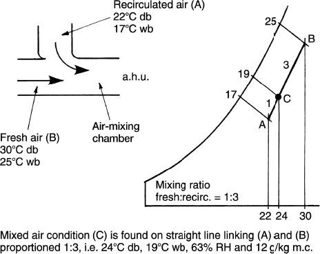
Psychrometric Chart Applications – Air Mixing
Mixing of two air-streams frequently occurs when combining fresh air with recirculated air from within the building. The process can be represented on a psychrometric chart by drawing a straight line between the two conditions and calculating a point relative to the proportions of mass flow rates.
Example 1:
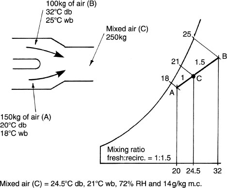
Example 2:
Psychrometric Chart Applications – Plant Sizing
The calculation below relates to the example on page 297, where cool intake air at 5°C db, 60% RH is conditioned to 20°C db, 50% RH.
Applied to an office of 2400m3 volume, requiring three air changes per hour, the quantity of air (Q) delivered will be:
![]()
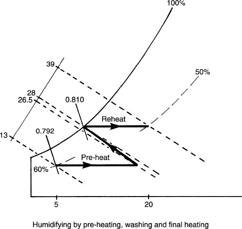
Pre-heater enthalpy = 26·5 – 1 3 = 13·5kJ/kg. Specific volume = 0·792 m3/kg
Reheater enthalpy = 39 – 28 = 11 kJ/kg. Specific volume = 0.810m3/kg
Pre-heater
Specific volume converted to kg/s: 2·0m3/s ÷ 0·792m3/kg = 2·53kg/s
Pre-heater rating: 2·53kg/s × 13·5kJ/kg = 34·2kW
Reheater
Specific volume converted to kg/s: 2·0m3/s ÷ 0·810m3/kg = 2·47kg/s
Reheater rating: 2·47kg/s × 11 kJ/kg = 27·2kW
The calculation below relates to the example on page 297, where warm intake air at 30°C db, 70% RH is conditioned to 20°C db, 50% RH.
With reference to the situation given on the previous page, the quantity of air delivered will be taken as 2m3/s.
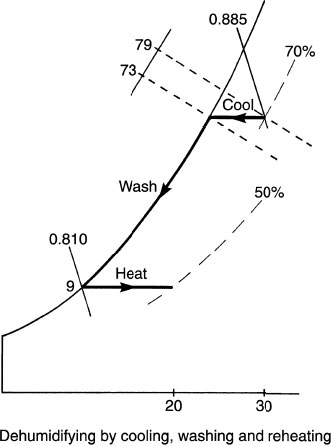
Chiller enthalpy = 79 – 73 = 6kJ/kg. Specific volume = 0·885m3/kg
Specific volume converted to kg/s: 2·0m3/s ÷ 0·885m3/kg = 2·26kg/s
Chiller rating: 2·26kg/s × 6kJ/kg = 13·6kW
Note: Calculations on this and the preceding page assume 100% efficiency of plant. This is unrealistic; therefore energy exchangers should be overrated to accommodate this.
E.g. If the chiller is 80% efficient, it will be rated: 13·6 × 100/80 = 17kW
Psychrometric Chart Applications – Condensation
Internal surface condensation can be minimised by providing a balance between heating, ventilation and insulation. Inadequate, intermittent or partial heating can produce a situation where the internal surfaces are colder than adjacent air temperatures. This will attract dampness to the surfaces from the moisture in the warmer air. A low rate of ventilation will also encourage a high level of humidity.
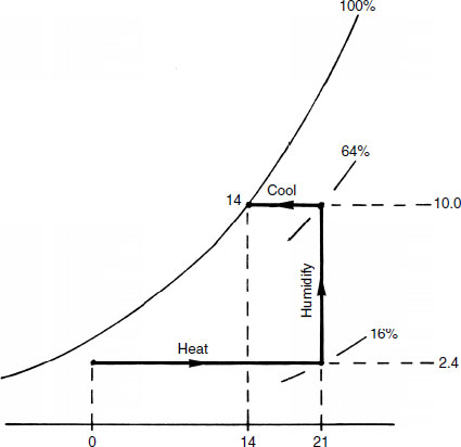
As shown in the diagram, external and internal environmental conditions can be plotted on a psychrometric chart to predict the risk of surface condensation.
E.g.
External air conditions:
0°C dry bulb temperature
2·4g/kg moisture content
Internal air conditions:
Air warmed to 21°C dry bulb temperature
Supply air moisture content remains at 2·4g/kg
RH or percentage saturation reduces to 16%
Internal activities add 76g/kg to moisture content (10g/kg total)
RH or percentage saturation increases to 64%
Condensation is shown to occur at 14°C or below. Otherwise known as a dew point temperature of 14°C db and 14°C wb at 100% RH.
A heat pump is in principle a refrigeration cycle operating in reverse by extracting heat from a low temperature source and upgrading it to a higher temperature for heat emission or water heating. The low temperature heat source may be from water, air or soil which surrounds the evaporator.
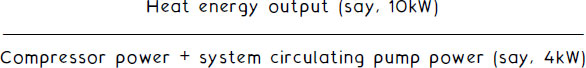
A heat pump must be energy efficient; it must generate more power than that used to operate it. A measure of theoretical coefficient of performance (COP) can be expressed as:
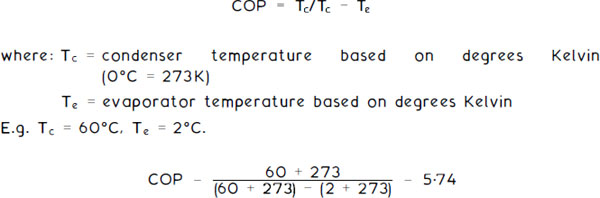
i .e. 5·74kW of energy produced for every 1kW absorbed. Allowing for efficiency of equipment and installation, a COP of 2 to 3 is more likely.

Note: The flow of the refrigerant can be reversed so that the building is warmed in winter and cooled in summer.
Heat pump units are available as large items of plant that can be used to warm a whole building. However, small, self-contained units are more common. These are usually located under window openings for warm and cool air distribution in winter and summer respectively.
To transfer the warmth in stale extract duct air, water may be circulated through coils or energy exchangers in both the extract and cool air-intake ducts. This is known as a run-around coil and is shown in greater detail on page 307. Using water as the energy transfer medium is inexpensive but limited in efficiency. Use of a refrigerant is more effective, with an evaporator coil in the warm extract duct and a condenser coil in the cold air inlet duct.
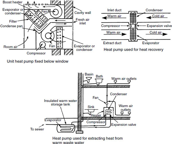
Heat energy in warm waste water from sanitary fittings may be retrieved and used to supplement space heating by using a heat pump. An insulated tank buried below ground receives the waste water before it flows to the sewer. Heat energy is extracted through an evaporator inside the tank.
The energy source for heat pumps can originate from the natural low heat in water, air and ground. The main energy-processing components are the source, the pump and the transfer.
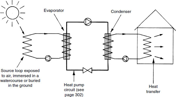
The principle is to absorb the heat from a low energy source, raise it in temperature and transfer it to storage or distribution.
Energy sources:
Water in a standing body of some depth is preferred, typical of docklands or deep canals, although warm wastewater has potential as shown on the previous page. The source water can be used directly as an open-loop system in a run-around coil – see page 307.
Air is the least efficient in variable climate conditions due to its relatively low specific heat capacity. Application is comparably easy as groundwork and ground space is not required Extractors can be installed on the inside or outside of an external wall.
Ground loops can be horizontal within a few metres of the surface or vertical in boreholes of several metres’ depth. Ground temperatures are fairly constant at 10°C, optimising equipment use. Application can be through polythene pipes containing a pumped distribution of water/antifreeze mixture between loop and evaporator.
Ground source heat pumps:
Objective – to extract heat from the thermal store of energy through pipes embedded in the ground. This energy store is absorbed from solar radiation, even during the winter. A pumped circuit between immersed pipes and heat pump evaporator contains a water/antifreeze mix or brine (salt dilution in water).
Ground temperature – 8 to 12°C within 15m of the surface.
Application – an immersed high-density polyethylene (HDPE) pipe loop (see previous page) is laid coiled in trenches 1.5 to 2.0m below the surface. Pipes may also be positioned vertically in a ‘U’ formation to greater depths.
Operation – relatively low-temperature water piped from the ground circuit to the heat pump evaporator has its heat energy exchanged into energy in a refrigerant before this is compressed to produce higher temperature energy at the condenser. Temperature at the condenser can be as high as 50°C. The condenser can be used to preheat boiler water for domestic use or it can be the source of medium- temperature water for underfloor heating.
Data – 0.414kg of carbon is produced for every kWh of electricity used. 0.194 kg of carbon is produced for the same amount of gas used in a condensing boiler. If the boiler is 85% efficient, then: 0.194 × (100 ÷ 85) = 0.228kg.
Example – given a gshp operating at 300% efficiency, i.e. three times more energy output than that used to power the compressor and ground pump loop (COP of 3, see page 302).
0.414kg of carbon becomes 0.138kg. Significantly less than that produced directly by electricity or the equivalent with gas at 0.228kg. Expressed another way, not only does this show carbon efficiency, but up to 3kW of energy is provided for every 1kW used, representing a substantial fuel cost saving.
Air source heat pumps:
Objective – to extract the heat energy contained in air outside a building using a fan unit to transfer its potential into heat energy in stored hot water or into heat emitters. The heat energy in air alone is insufficient, but it can be upgraded by applying the principle of a heat pump refrigeration cycle. The heat energy in outside air is extracted in the same way that a domestic refrigerator extracts heat energy from the air within its storage compartment.
Function – the outside fan unit contains the evaporator component of a refrigeration cycle which contains refrigerant in a vapour/liquid state. As the refrigerant absorbs heat from the air it evaporates and is compressed/pressurised to increase its temperature to about 1000 C at the condenser. The condenser coil containing this high-temperature vaporised refrigerant is immersed in water and functions as a heat exchanger serving a hot water storage facility or a heating circuit. As the water absorbs heat energy from the condenser coil, the refrigerant within the coil loses temperature and condenses back to a liquid. Thereafter it passes through the restriction of an expansion valve to reduce refrigerant pressure and temperature further, before vaporising in the evaporator to continue the cycle.
Refrigerant – the type used is in the azeotropic category, typically R407c, see pages 286 and 287.
Efficiency – dependent on outside air temperature relative to heated water design temperature. As air temperatures are limited in the UK, air to water heat pumps are most suited to reduced temperature applications such as underfloor heating circuits, i.e. 40°C to 50°C. Radiators will need to be significantly oversized to compensate unless there is a supplementary heat source from a boiler.
Theoretical COP –
Therefore, COP = 2.5
The run-around coil can be used as a direct energy transfer system or as a system of heat recovery.
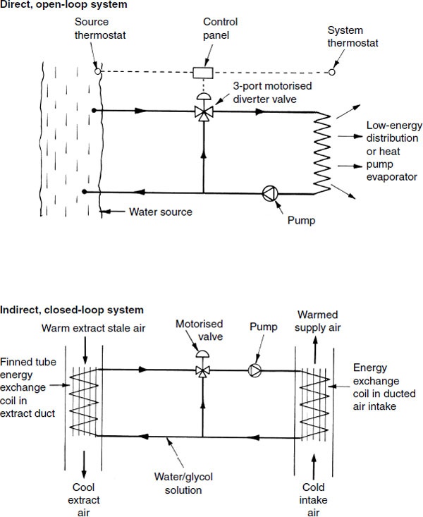
Note: Long and uninsulated pipe runs will limit efficiency.
The concept of a thermal or heat wheel was devised about 50 years ago by Carl Munter, a Swedish engineer. Wheels range from 600mm to 4 m in diameter, therefore sufficient space must be allowed for their accommodation. They have an extended surface of wire mesh or fibrous paper impregnated with lithium chloride. Lithium chloride is an effective absorbent of latent heat energy in the moisture contained in stale air. A low-power (700W) electric motor rotates the wheel at an angular velocity of 10–20rpm. Heat from the exhaust air transfers to the inlet air and the purging section extracts the contaminants. Efficiency can be up to 90%.
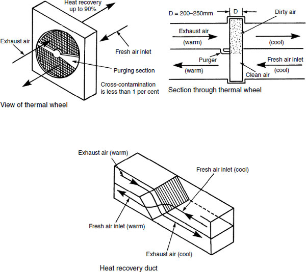
The heat recovery duct or plate heat exchanger has warm exhaust air separated from the cool inlet air by metal or glass vanes. Heat from the exhaust vanes is transferred to the inlet vanes to warm the incoming air. Ducts must be well insulated to conserve energy and to reduce condensation. Condensation should be drained at the base of the unit. Efficiency is unlikely to exceed 50%.
Health Considerations, Legionnaires’ Disease
Buildings are designed with the intention of providing a comfortable internal environment. To achieve this efficiently, many incorporate air- conditioning and ventilation systems. Misuse of some of the system equipment may cause health hazards to the occupants.
Legionnaires’ disease – obtained its name from the first significant outbreak that occurred during an American Legionnaires – convention at a hotel in Philadelphia, USA in 1976. The bacterial infection was contracted by 221 people; it has similar symptoms to pneumonia. Of these, 34 died. Subsequently, numerous outbreaks have been identified worldwide, not least in the UK. They are generally associated with hot water systems (see page 128) and air-conditioning water cooling towers.
The organisms responsible occur naturally in swamps and similar humid conditions. In limited numbers they are harmless, but when concentrated they contaminate the water in which they live. If this water is suspended in the air as an aerosol spray, it can be inhaled to establish lung disease in susceptible persons.
Other worst-known outbreaks –
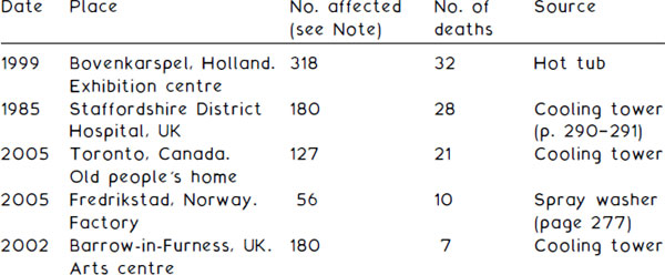
Note: Figures given for number affected vary between different information data resources, as those exposed and showing pneumonia-type symptoms were not definitely affected by the LD bacteria. Also, some with milder respiratory illnesses may have been affected by the same bacteria but suffered only flu-like symptoms. This is known as Pontiac Fever.
Water systems with a temperature between 20°C and 60°C. The optimum breeding temperature of the bacteria is about 40°C.
Water cooling towers, particularly the older type with coarse timber packing. Where located in dirty and dusty atmospheres typical of that found close to building sites in busy city centres, contaminated spray dispersed in the air may be inhaled by people in the vicinity. The spray may also be drawn into ventilation inlets of adjacent buildings and be distributed through the ductwork.
Water in spray humidifiers can be affected by contaminated air drawn into air-processing units. Humidifiers are a possible breeding area for bacteria unless the water is strongly dosed with biocide. They should be replaced with steam humidifiers.
People most at risk –
The elderly, those with existing respiratory problems, heavy smokers and those in a generally poor state of health. Nevertheless, there have been many incidents of fit, healthy young people being infected.
Solution –
Abolition of wet cooling towers and replacement with air-cooled condensers.
Use of packaged air conditioning with air cooling.
Documented maintenance of plant and equipment, particularly wet cooling towers to involve regular draining, cleaning, water replacement and treatment with a biocide.
Outlook –
In the UK there are around 300 new occurrences of LD every year. Due to public awareness, cure is successful if detection and diagnosis is early enough. However, the bacteria are becoming more resilient and concern is that they can resist and breed at higher temperatures. Solar heating can produce stored water at temperatures compatible with the bacteria flourishing; therefore these systems must be supported with hot water temperature control capable of eliminating the bacteria.
Refs. Workplace (Health, Safety and Welfare) Regulations.
HSE Approved Code of Practice and Guidance (L8): The Control of Legionella Bacteria in Water Systems.
Other Building-related Illnesses
Humidifier fever – this is not an infection, but an allergic reaction producing flu-like symptoms such as headaches, aches, pains and shivering. It is caused by micro-organisms which breed in the water reservoirs of humidifiers while they are shut down, i.e. weekends or holidays. When the plant restarts, concentrations of the microorganisms and their dead husks are drawn into the air stream and inhaled. After a few days’ use of the plant, the reaction diminishes and recommences again after the next shutdown. Water treatment with a biocide is a possible treatment or replacement with a steam humidifier.
Sick building syndrome – this is something of a mystery as no particular cause has been identified for the discomfort generally attributed to this disorder. The symptoms vary and can include headaches, throat irritations, dry or running nose, aches, pains and loss of concentration. All or some may be responsible for personnel inefficiency and absenteeism from work. While symptoms are apparent, the causes are the subject of continued research. Some may be attributed to physical factors such as:
Noise from computers, machinery, lighting or ducted air movement.
Strobing from fluorescent strip lights.
Static electricity from computer screens, copiers, etc.
Fumes from cleaning agents.
Glare from lighting and monitors.
Unsympathetic internal colour schemes.
Carpet mites.
Other factors are psychological:
Lack of personal control over an air-conditioned environment.
No direct link with the outside world, i.e. no openable windows.
Disorientation caused by tinted windows.
Working in rooms with no windows.
Dissatisfaction with air conditioning does not provide the ideal environment.
More apparent may be lack of maintenance and misuse of air-conditioning plant. Energy economising by continually recirculating the same air is known to cause discomfort for building occupants. The research continues and, as a result of sick building syndrome, new building designs often favour more individual control of the workplace environment or application of traditional air movement principles such as stack effect.