
9 Sanitary Fitments and Appliances: Discharge and Waste Systems

Flushing Cisterns, Troughs and Valves
Thermostatic Temperature Control
Sanitary Conveniences for Disabled People
Single-Stack System and Variations
Wash Basins – Waste Arrangements
Washing Machine and Dishwasher Wastes
Ground-Floor Appliances – High-Rise Buildings
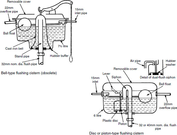
Bell type – this form of flushing cistern is now virtually obsolete, although some reproductions are available for use in keeping with the refurbishment of historic premises. Cast iron originals may still be found in use in old factories, schools and similar established buildings. It is activated by the chain being pulled which also lifts the bell. As the chain is released the bell falls to displace water down the stand pipe, effecting a siphon which empties the cistern. The whole process is relatively noisy.
Disc type – manufactured in a variety of materials including plastics and ceramics for application to all categories of building. Depressing the lever raises the piston and water is displaced over the siphon. A siphonic action is created to empty the cistern. Some cisterns incorporate an economy or dual-flush siphon. When the lever is depressed and released promptly, air passing through the vent pipe breaks the siphonic action to give a 4.5-litre flush. When the lever is held down a 7.5-litre flush is obtained. Since 2001 the maximum permitted single flush to a WC pan is 6 litres.
Refs. BS 1125 and 7357: Specifications for WC flushing cisterns.
The Water Supply (Water Fittings) Regulations 1999.
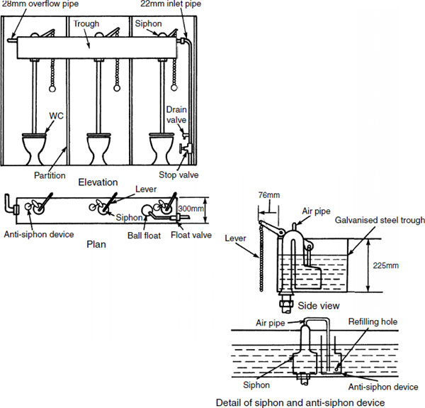
A flushing trough may be used as an alternative to several separate flushing cisterns where a range of WCs are installed. They are particularly applicable to school, factory and office sanitary accommodation. Trough installation is economic in equipment and time. It is also more efficient in use as there is no waiting between consecutive flushes. The disadvantage is that if it needs maintenance or repair, the whole range of WCs are unusable. The trough may be bracketed from the rear wall and hidden from view by a false wall or ceiling.
The siphon operates in the same manner as in a separate cistern, except that as water flows through the siphon, air is drawn out of the air pipe. Water is therefore siphoned out of the anti-siphon device, the flush terminated and the device refilled through the small hole.
Roger Field’s flushing cistern is used for automatically flushing WCs. It has application to children’s lavatories and other situations where the users are unable to operate a manual flush device. As the cistern fills, air in the stand pipe is gradually compressed. When the head of water ‘H’ is slightly above the head of water ‘h’, water in the trap is forced out. Siphonic action is established and the cistern flushes the WC until air enters under the dome to break the siphon.
With the smaller urinal flush cistern, water rises inside the cistern until it reaches an air hole. Air inside the dome is trapped and compressed as the water rises. When water rises above the dome, compressed air forces water out of the ‘U’ tube. This lowers the air pressure in the stand pipe, creating a siphon to empty the cistern. Water in the reserve chamber is siphoned through the siphon tube to the lower well.

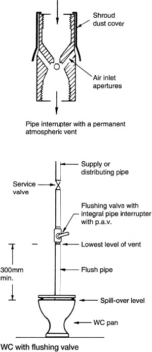
Flushing valves are a more compact alternative to flushing cisterns, often used in marine applications, but may only be used in buildings with approval of the local water authority. The device is a large equilibrium valve that can be flushed at any time without delay, provided there is a constant source of water from a storage cistern. The minimum and maximum head of water above valves is 2·2m and 36m respectively. When the flushing handle is operated, the release valve is tilted and water is displaced from the upper chamber. The greater force of water under piston ‘A’ lifts valve ‘B’ from its seating and water flows through the outlet. Water flows through the bypass and refills the upper chamber to cancel out the upward force acting under piston ‘A’. Valve ‘B’ closes under its own weight.

The minimum flow rate at an appliance is 1·2 litres per second. By domestic standards this is unrealistically high, therefore pressure flushing valves are not permitted in houses.
Where connected to a mains supply pipe or a cistern distributing pipe, a flushing valve must include a backflow prevention device having a permanently vented pipe interrupter situated at least 300mm above the spill-over level of the served WC.
If a permanently vented pipe interrupter is not fitted, the water supply to a flushing valve must be from a dedicated cistern with an air gap (see page 53) below its float valve delivery.
The maximum flush in a single operation is 6 liters.
Flushing valves may be used to flush urinals. In this situation they should deliver no more than 1·5 litres of water to each bowl or position per operation. See page 407.
Washdown Water Closet and Joints
The washdown WC pan is economic, simple and efficient. It rarely becomes blocked and can be used in all types of buildings with colour variations to suit internal decor. Manufacture is primarily from vitreous china, although glazed fireclay and stoneware have been used. Stainless steel WCs can be specified for use in certain public areas and prisons. Pan outlet may be horizontal, ‘P’, ‘S’, left- or right-handed. Horizontal outlet pans are now standard, with push-fit adaptors to convert the pan to whatever configuration is required. Plastic connectors are commonly used for joining the outlet to the soil branch pipe. The flush pipe joint is usually made with a rubber cone connector which fits tightly between WC and pipe.
WC pan outlet <80mm, trap diameter = 75mm
WC pan outlet >80mm, trap diameter = 100mm
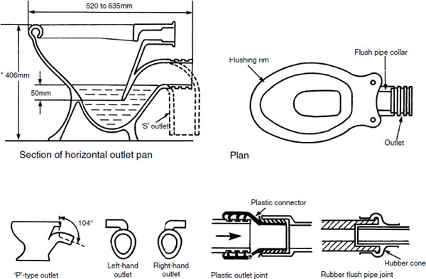
*Note: Add approximately 25mm to the top of the WC to allow for seat height. Overall height for the disabled is 480mm, junior schoolchildren 355mm and infants 305mm.
Refs. BS EN 997: WC pans and WC suites with integral trap.
BS EN 33: WC pans and WC suites. Connecting dimensions.
Siphonic WCs are much quieter in operation than washdown WCs and they require less flush action to effect an efficient discharge. They are not suitable for schools, factories and public buildings as they are more readily blocked if not used carefully.
The double-trap type may be found in house and hotel bathrooms. When flushed, water flows through the pressure-reducing fitting ‘A’. This reduces the air pressure in chamber ‘B’. Siphonic action is established and the contents of the first trap are removed. This is replenished from reserve chamber ‘C’.
The single-trap variant is simpler and has limited application to domestic bathrooms. When the cistern is flushed, the content is discharged through the trap and restricted in flow by the specially shaped pan outlet pipe. The pipe fills with water which causes a siphonic effect. Sufficient water remains in the reserve chamber to replenish the seal.

A bidet is classified as a waste fitting. The requirements for a discharge pipe from a bidet may therefore be treated in the same manner as a basin waste of the same diameter – nominally 32mm. It is an ablutionary fitting used for washing the excretory organs, but may also be used as a foot bath. Hot and cold water supplies are mixed to the required temperature for the ascending spray. For greater comfort the rim of the fitting may be heated from the warm water. Ascending spray-type bidets are not favoured by the water authorities because the spray nozzle is below the spill level, risking water being back-siphoned into other draw-off points. This is prevented by having independent supply pipes to the bidet which are not connected to any other fittings. A further precaution would be installation of check valves on the bidet supply pipes or a thermostatic regulator with integral check valves. Over-the-rim hot and cold supplies are preferred with an air gap (see page 53) between rim and tap outlets.

Ref. BS EN 35: Pedestal bidets with over-rim supply. Connecting dimensions.
A shower is more economical to use than a bath as it takes less hot water (about one-third), it is arguably more hygienic and it takes up less space. The mixing valve should be thermostatic (see pages 400–403) to avoid the risk of scalding. A minimum 1m head of water should be allowed above the shower outlet. If this is impractical, a pumped delivery could be considered (see next page). The shower outlet (rose) should also be at least 2m above the floor of the shower tray. Supply pipes to individual showers are normally 15mm o.d. copper or equivalent. These should incorporate double-check valves if there is a flexible hose to the rose, as this could be left in dirty tray water which could back-siphon. An exception to check valves is where the shower head is fixed and therefore well above the air gap requirements and spill-over level of the tray.

Refs. BS EN 251: Shower trays. Connecting dimensions.
BS 6340: Shower units (various specifications).
BS EN 263: Sanitary appliances. Cross-linked cast acrylic sheets for baths and shower trays for domestic purposes.
Where the 1m minimum head of water above the shower outlet is not available and it is impractical to raise the level of the supply cistern, a pump can be fitted to the mixer outlet pipe or on the supply pipes to the mixer. The pump is relatively compact and small enough to be installed on the floor of an airing cupboard or under the bath. It must be accessible for maintenance, as the pump should be installed with filters or strainers which will require periodic attention, particularly in hard water areas. The pump will operate automatically in response to the shower mixer being opened. A pressure sensor and flow switch detect water movement to activate the pump and vice versa. Electricity supply can be from an isolating switch or pull cord switch with a 3 amp fuse overload protection spurred off the power socket ring main.

Note: Double-check valves may be required on the supply pipes as described on the previous page. The mixing valve and pump may incorporate check valves – refer to manufacturer’s information.
Minimum cold water storage 230 litres per bathroom, 365 litres for one bathroom and an en-suite shower room. Where two or more bathrooms are provided, a 28mm o.d. min. cold feed pipe to the hwsc should be used. Water supplies to the pump can be the first tee-branch connection, but as shown below an independent arrangement is preferable.

Note: Water supply to a shower pump is not to be taken direct from the mains.
Pump located above the hot water connection to the hot water storage cylinder, e.g. in a roof void.

Note: With anti-gravity loop hot water supply, the stored water temperature is limited to reduce the possibility of gravity circulation and aeration.
Pumps provided for a multiple shower situation, e.g. sports complex.

Note: For all types of installation, the pump manufacturer’s data should be consulted for recommended pipe sizes. For most domestic situations the gravity feed is 22mm o.d. copper and the pumped supply 15mm o.d. copper.
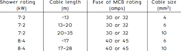
Instantaneous electric water heating for showers is an economical, simple-to-install alternative to a pumped shower. This is particularly apparent where there would otherwise be a long secondary flowpipe from the hot water storage cylinder to the shower outlet, possibly requiring additional secondary return pipework to avoid a long ‘dead leg’ Cold water supply is taken from the rising main in 15mm o.d. copper tube. This will provide a regulated delivery through the shower unit of up to 3 litres/min. The unit contains an electric element, usually of 7·2 or 8·4kW rating. It also has a number of built-in safety features:
Automatic low-pressure switch to isolate the element if water pressure falls significantly or the supply is cut off.
Thermal cut-off. This is set by the manufacturer at approximately 50°C to prevent the water from overheating and scalding the user.
Non-return or check valve on the outlet to prevent back-siphonage.
Electricity supply is an independent radial circuit, originating at the consumer unit with a miniature circuit breaker (MCB) appropriately rated. Alternatively a suitable rated fuse way may be used in the consumer unit and added protection provided with an in-line residual current device (RCD) trip switch. All this, of course, is dependent on there being a spare way in the consumer unit. If there is not, there will be additional expenditure in providing a new consumer unit or a supplementary fuse box. A double pole cord-operated pull switch is located in the shower room to isolate supply.
Ref. BS 6340: Shower units (various specifications).

Baths are manufactured in acrylic sheet, reinforced glass fibre, enamelled pressed steel and enamelled cast iron. The acrylic sheet bath has the advantage of light weight to ease installation, it is comparatively inexpensive and is available in a wide range of colours. However, special cleaning agents must be used, otherwise the surface can become scratched. It will require a timber support framework, normally laid across metal cradles. Traditional cast iron baths are produced with ornate feet and other features. Less elaborate, standard baths in all materials can be panelled in a variety of materials including plastic, veneered chipboard and plywood.
The corner bath is something of a luxury. It may have taps located to one side to ease accessibility. A Sitz bath is stepped to form a seat. It has particular application to nursing homes and hospitals for use with the elderly and infirm.

Refs. BS 1189 and 1390: Specifications for baths made from porcelain enamelled cast iron and vitreous enamelled sheet steel, respectively.
BS 4305–2: Baths for domestic purposes made of acrylic material.
BS EN 232: Baths. Connecting dimensions.
BS EN 198: Sanitary appliances. Baths made from cross-linked cast acrylic sheets. Requirements and test methods.
Sinks are designed for culinary and other domestic uses. They may be made from glazed fireclay, enamelled cast iron or steel, stainless steel or from glass fibre-reinforced polyester.
The Belfast sink has an integral weir overflow and water may pass through this to the waste pipe via a slotted waste fitting. It may have a hardwood or dense plastic draining board fitted at one end only or a draining board fitted at each end. Alternatively, the sink may be provided with a fluted drainer of fireclay. The London sink has similar features, but it does not have an integral overflow. In recent years sinks of this type have lost favour to surface built-in metal and plastic materials, but there is now something of a resurgence of interest in these traditional fittings. Stainless steel sinks may have single or double bowls, with left- or right-hand drainers or double drainers. These can be built into a work surface or be provided as a sink unit with cupboards under. The waste outlet is a standard 40mm nominal diameter.

Refs. BS 1206: Specification for fireclay sinks, dimensions and workmanship.
BS EN 13310: Kitchen sinks. Functional requirements and test methods. Building Regulations, Approved Document G6: Kitchens and food preparation areas.
These are rarely necessary in domestic situations, but have an application to commercial premises, schools, hospitals and similar public buildings. They are usually located inside the cleaning contractor’s cubicle and are fitted at quite a low level to facilitate ease of use with a bucket. They are normally supported by built-in cantilever brackets and are additionally screwed direct to the wall to prevent forward movement. 13mm bore (halfinch) hot and cold water draw-off bib-taps may be fitted over the sink, at sufficient height for a bucket to clear below them. 19mm bore (three-quarter-inch) taps may be used for more rapid flow. A hinged stainless steel grating is fitted to the sink as a support for the bucket. The grating rests on a hardwood pad fitted to the front edge of the sink to protect the glazed finish. A 40mm nominal diameter waste pipe is adequate for this type of sink.
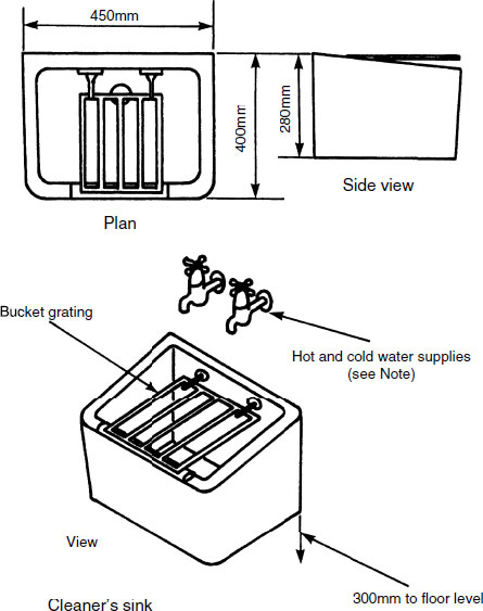
Note: For all sanitary fitments, the convention of hot tap to the left and cold tap to the right applies.
There are various types of basin, ranging in size and function from hand rinsing to surgical use. A standard basin for domestic application to bathrooms and cloakrooms consists of a bowl, soap tray, weir overflow and holes for taps and outlet. It may be supported by cast iron brackets screwed to the wall, a corbel which is an integral part of the basin built into the wall or a floor pedestal which conceals the pipe work. Water supply is through 13mm (half-inch) pillar taps for both hot and cold. A standard 32mm nominal diameter waste outlet with a slot to receive the integral overflow connects to a trap and waste pipe of the same diameter. A plug and chain normally controls outflow, but some fittings have a pop-up waste facility.
Most basins are made from coloured ceramic ware or glazed fireclay. There are also metal basins produced from stainless steel, porcelain enamelled sheet steel or cast iron.

Refs. BS 1188: Specification for ceramic wash basins and pedestals.
BS 5506–3: Specification for wash basins.
BS EN 31: Wash basins. Connecting dimensions.
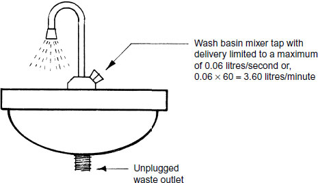
Washing troughs are manufactured circular or rectangular on plan in ceramic materials or stainless steel. They are an economical and space-saving alternative to a range of basins, for use in factory, school and public lavatories. Some variations have an overall umbrella spray or fountain effect operated by a foot pedal. These are no longer favoured by the water supply undertakings as a trough must have a separate draw-off tap for every placement. In common with other sanitary fitments, there must be provision to prevent the possibility of back-siphonage, i.e. an adequate air gap between tap outlet and spill level of the trough. Hot and cold water supply to the taps is thermostatically blended to 40°C maximum.

Note: Draw-off taps adapted or purposely designed to deliver a maximum of 0.06 l/s (3.6 l/min)
To prevent an excess of water use and unnecessary waste, most sanitary appliances are fitted with a means for plugging the waste outlet. Baths, basins, sinks and similar use appliances intended to contain a volume of water for washing should have attached or be fitted with a readily accessible plug or other device such as a pop-up waste closer.
Exceptions –
Appliances fitted with spray taps only.
Washing troughs, as shown on the preceding page.
Washing appliances (basins or troughs) with self-closing taps.
Shower trays or baths used with only a shower supply.
Drinking water fountains.
Purpose-made appliances for use in medical, dentistry and veterinary situations, e.g. dentist’ s mouthwash bowl.
Wash basins with water supply restricted to a 0.06 litres/second maximum flow.
Ref. The Water Supply (Water Fittings) Regulations, Schedule 2, Para. 28.
Safe water temperature – safety is considered from two perspectives:
Legionella or Legionnaires’ disease – 60 to 65°C stored hot water requirement to prevent development of the bacteria.
Scalding – water temperatures above 45°C can cause injury.
Recommended maximum temperatures at draw-off points are:
Appliance |
Temperature °C |
|---|---|
Bath |
43 |
Shower |
40 |
Hand basin |
40 |
Bidet |
37 |
Sink |
48 |
As can be seen, there is a conflicting temperature differential between the two perspectives of about 20°C. Therefore, scalding is possible unless measures are introduced to blend the hot water supply with cooler water.
Mixing valve types:
Type 1 (TMV 1) – mechanical mixing with an over temperature stop to BS EN 1286: Sanitary tapware. Low-pressure mechanical mixing valves. General technical specification. Or, BS 5779: Specification for spray mixing taps.
Type 2 (TMV2) – thermostatic mixing to BS EN 1287: Sanitary tapware. Low-pressure thermostatic mixing valves. General technical specification. Or, BS EN 1111: Sanitary tapware. Thermostatic mixing valves (PN 10). General technical specification.
Type 3 (TMV 3) – thermostatic mixing with enhanced thermal performance. This should comply with NHS Estates Model Engineering Specification DO8, thermostatic mixing valves (healthcare premises).

Any newly built property or an existing property subject to alterations or refurbishment that include bathroom facilities must incorporate a device to prevent the hot water supply to a bath or a bidet from exceeding 48°C. This device will usually be a thermostatic mixing valve required to be set between 44°C and 46°C with a +/− tolerance of 2°C. In due course, these Building Regulation requirements may be applied to hot water temperatures at the outlets of other sanitary fitments. The need for these controls is in response to the unacceptably high number of scalding incidents through hot water supplied at normal storage temperature of about 60°C, as accounted for at the top of the preceding page.
This objective of safe hot water outlet temperatures can be achieved by installing a thermostatic mixing valve to blend cold and hot water supplies before they discharge through a terminal fitting, i.e. a tap or a shower rose. The basic mixing valve shown on the previous page has a temperature-sensitive element that responds to inlet water temperature changes to ensure a stable outlet temperature. In addition to this blending facility, the outlet must also have an over-temperature detection element and valve to close the delivery if the cold water supply fails or if the sensitive element within the mixing unit malfunctions.
Thermostatic mixing valves to TMV1 specification have largely been superseded by the higher expectations of TMV2 standards. However,
the TMV1 specification is still acceptable in situations where persons using the blended water supply are not considered to be at any risk. This generally excludes use in premises occupied by children, elderly or infirm people. Valves to TMV2 specifications will normally satisfy the standards expected for domestic use, i.e. installation in dwellings, housing association properties, hotels and hostels. Valves to TMV3 specification are for higher risk situations, such as nursing/convalescent homes and hospitals.
Refs. Building Regulations Part G, AD G3: Hot Water Supply and Systems.
Building Research Establishment, Information Paper IP 14/03, Preventing hot water scalding in bathrooms: using TMVs.
BS 7942: Thermostatic mixing valves for use in care establishments.


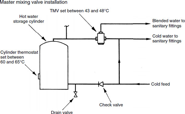
The stored hot water temperature must be at least 60°C to prevent the development of bacteria. Therefore, simply setting the hot water storage cylinder thermostat to provide a general supply of hot water at about 48°C is prohibited. Subject to the local water supply authority’s requirements and approval, it may be possible to install just one central or master thermostatic mixing valve, to regulate domestic hot water requirements to all fitments as shown in principle below.
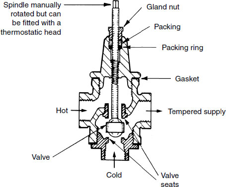
A tempering valve can be used to provide a simple means for temperature control of potable hot water distribution to several sanitary fitments. It therefore has application to large-scale domestic and commercial sanitary plumbing installations. It can also be used for industrial process water supplies. Unlike TMVs that are normally provided as dedicated point-of-use water temperature controls to every sanitary fitting, only one tempering valve is used for a whole system and this should be fitted as close as practical to the hot water source. Therefore, the installation costs with a tempering valve are relatively economical for large systems of sanitation where good overall temperature control is adequate.
A tempering valve functions by blending cold and hot water in proportional volumes without significantly impeding the flow rate. The valve can be set manually where precise temperature control is not a requirement, but where used to supply sanitary appliances an antiscald protection measure by automatic thermostatic control set to a maximum of 48°C will be necessary. Thermostatic tempering valves are produced for this purpose.
Ref. BS EN 15092: Building valves. Inline hot water supply tempering valves. Tests and requirements.
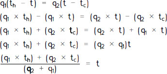
When mixing hot water with cold water to provide a blended supply, the quantities and temperatures of each can be estimated relative to the required water temperature objective. Factors such as lengths of individual supply pipes, effect of pipe insulation if and where provided and slight variances in water density at different temperatures will make a nominal contribution and may be included for academic reasons. However, for practical purposes, the formula procedure shown below will provide an adequate approximation:
Heat lost by hot water supply = Heat gained by cold water supply
Heat lost by hot water supply = q1(th − t)
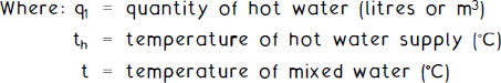
Heat gained by cold water supply = q2(t − tc)

Therefore:
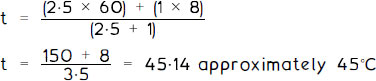
Example: A thermostatic mixing valve is set to blend hot water at 60°C with cold water at 8°C in the proportion of 2·5:1, i.e. 2·5 litres of hot water for every 1 litre of cold water. The resultant delivery temperature will be:
These are used in virtually all buildings and public lavatories containing common facilities for male conveniences. They reduce the need for a large number of WCs. Three formats are available in ceramic ware or stainless steel:
Bowl – secured to the wall and provided with division pieces where more than one is installed.
Flat slab – fixed against the wall with projecting return end slabs and a low-level channel.
Stall – contains curved stalls, dividing pieces and low-level channel.
Urinals are washed at intervals of 20 minutes by means of an automatic flushing cistern discharging 4·5 litres of water per bowl of 610 mm of slab/stall width. The water supply to the cistern should be isolated by a motorised valve on a time control, to shut off when the building is not occupied. A hydraulically operated inlet valve to the automatic flushing cistern can be fitted. This closes when the building is unoccupied and other fittings not used.

Refs. BS 4880–1: Specification for urinals. Stainless steel slab urinals.
BS 5520: Specification for vitreous china bowl urinals.
BS EN 80: Wall hung urinals. Connecting dimensions.
Urinals – Manual Flushing Devices
See page 382 and preceding page for automatic devices.
Urinals usually have automatically operated flushing mechanisms. However, manual operation is also acceptable by use of:
Flushing cistern.
Flushing valve.
Wash basin tap and hydraulic valve (combination of manual and automatic).

Special types of sanitary appliances are required for hospital sluice rooms. The slop hopper is used for the efficient disposal of bedpan excrement and general waste. It is similar in design to the washdown WC pan, but has a hinged stainless steel grating for a bucket rest. Another grating inside the pan prevents the entry of large objects which could cause a blockage.
The bedpan washer has a spray nozzle for cleaning bedpans and urine bottles. To prevent possible contamination of water supply, it is essential that the water supplying the nozzle is taken from an interposed cold water storage cistern used solely to supply the bedpan washer. Alternatively, the design of the bedpan washer must allow for an air gap (min. 20mm) between spray outlet nozzle and water spill level. A 90mm nominal diameter outlet is provided for the pan.

Sanitary Conveniences – Building Regulations
Approved Document G4 provides for minimum quantity, use and disposition of sanitary conveniences. These should contain sufficient appliances relative to a building’s purpose and be separated by a door from places where food is stored or prepared. Layout of appliances and installation should allow for access and cleaning. The diagrams illustrate various locations for sanitary conveniences, with an intermediate lobby or ventilated space as required. En-suite facilities are acceptable direct from a bedroom, provided another sanitary convenience is available in the building. All dwellings must have at least one WC with a wash basin facility. The wash basin should be located in the room containing the WC or in a room or space giving direct access to the WC room (provided that it is not used for the preparation of food). A dwelling occupying more than one family should have the sanitary facilities available to all occupants.

Refs. Building Regulations, Approved Document G4: Sanitary conveniences and washing facilities.
Building Regulations, Approved Document F1 – Means of ventilation.
Sanitary Conveniences – BS 6465
The British Standard recommends that every new dwelling is fitted with at least one WC, one bath or shower, one wash basin and one sink. In dwellings accommodating five or more people there should be two WCs, one of which may be in a bathroom. Any WC compartment not adjoining a bathroom shall also contain a wash basin. Where two or more WCs are provided, it is preferable to site them on different floors.
The number of appliances recommended for non-domestic premises such as offices, factories, shops, etc. varies considerably. BS 6465–1 should be consulted for specific situations. A general guide is provided on the next page.
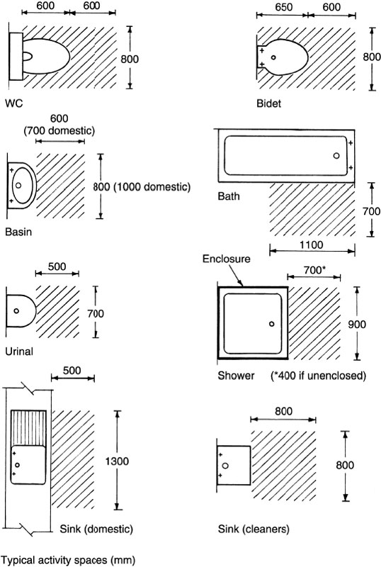
Bathroom arrangements are detailed in BS 6465–2. Some simple domestic layouts are shown below, with minimum dimensions to suit standard appliances and activity space.

Design of appliances should be such that they are smooth, impervious and manufactured from non-corrosive materials. They should be self- cleansing in operation and easily accessible for manual cleaning. Simplicity in design and a regard to satisfactory appearance are also important criteria.
Refs. BS 6465–1: Sanitary installations. Code of practice for the design of sanitary facilities and scales of provision of sanitary and associated appliances.
BS 6465–2: Sanitary installations. Code of practice for space requirements for sanitary appliances.
Sanitary Conveniences – Washrooms
The Offices, Shops and Railway Premises Act requires occupied buildings to have suitably located accommodation for sanitary appliances. This can be achieved by complying with the various regulations and other published guidance listed at the bottom of the page.
In general, the following minimum provisions apply:
Adequate ventilation
Regular cleaning schedule
Cold and hot running water, or mixed warm water
Means for cleaning (soap) and drying (towels or warm air)
Showers if the type of work justifies it
Toilet paper and coat hook in the WC cubicle
Privacy, preferably with separate male and female accommodation unless each facility is separated with a lockable door for use by one person at a time
Accessibility – not necessarily in the workplace but within the vicinity.
Minimum facilities:
Mixed use or female use only –
Persons |
WCs |
Washbasins |
|---|---|---|
1–5 |
1 |
1 |
6–25 |
2 |
2 |
Thereafter, one additional WC and one additional wash basin per 25 persons
Male use only –

Thereafter, allocated on the same proportional basis
Refs. Building Regulations, Approved Document G4: Sanitary conveniences and washing facilities.
BS 6465–1.
Workplace (Health, Safety and Welfare) Regulations.
Food Hygiene Regulations.
Sufficient space for comfort and accessibility should be provided within WC compartments. The following guidance accepts overlap of adjacent activities and door opening:
See also the following three pages for spatial and access requirements for disabled persons.
Sanitary Conveniences for Disabled People (Dwellings)
Objectives for WC provision:
In the entrance storey with unobstructed access.
Within the principal storey of habitable rooms if this is not at entrance level.
No higher than the principal storey – stair lift facility to other floors may be considered.
WC may be located within a bathroom provided that the bath and wash basin are positioned so as not to impede access.
Access door opens outwards. Inward opening may be considered if there is clear space for door swing and door can be opened outwards in an emergency.
Compartment to contain clear space as shown in diagrams.
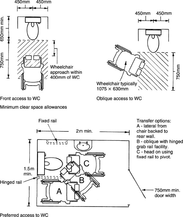
Sanitary Conveniences for Disabled People
Buildings other than dwellings – at least one unisex WC public lavatory to be provided in cinemas, concert halls, leisure/sports centres, large office buildings, recreational buildings and theatres.
Access dimensions:
Passageway width, min. 1200mm.
Passageway door opening width, min. 900mm.
WC compartment size, min. 2200 × 1500mm.
Door into compartment, min. 1000 mm clear width.
Note: Compartment door opens outwards. It should have an emergency release device operated from the outside and a horizontal bar for closing fitted to the inside.

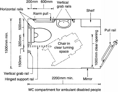
Facilities for ambulant (not confined to a wheelchair) disabled people should be provided within conventional separate-sex WC and washroom compartments. A suitable compartment will contain some appliances specifically fitted with support rails. There should also be sufficient space to accommodate persons with impaired leg movement and with crutches.
Other provisions and facilities in buildings other than dwellings:
Support/grab rails of 50mm minimum diameter, each side of a wash basin.
Hinged or drop-down rail at least 300mm long on the exposed side of a WC.
WC positioned to allow lateral transfer from a wheelchair.
WC seat of rigid and robust material, set to a height of 480mm above finished floor level (ffl).
Means for flushing, maximum 1200mm above ffl.
Toilet paper dispenser within easy reach and on the side closest to WC seat.
Wash basin height maximum 750mm and reachable while seated on WC pan.
Hand dryer preferred to towels. Unit fitted between 800 and 1000mm above ffl. Hot air temperature thermostatically set at a maximum of 35°C
Wash basin taps of the quarter-turn lever type, or an electric sensor operated discharge. Water temperature regulated to 35°C maximum.
Emergency alarm cord suspended from the ceiling, as close as possible to a wall. Cord fitted with two 50mm-diameter red bangles set at 100mm and between 800 and 1000mm above ffl.
Refs. Building Regulations, Approved Document M: Access to and use of buildings.
BS 8300: Design of buildings and their approaches to meet the needs of disabled people. Code of practice.
Disability Discrimination Act.
Foul air from the drain and sewer is prevented from penetrating buildings by applying a water trap to all sanitary appliances. A water seal trap is an integral part of gullies and WCs, being moulded in during manufacture. Smaller fittings (i.e. sinks, basins, etc.), must be fitted with a trap. The format of a traditional tubular trap follows the outline of the letter ‘P’ or ‘S’. The outlet on a ‘P’ trap is slightly less than horizontal ![]() and on an ‘S’ trap it is vertical. A ‘Q’ trap has an outlet inclined at an angle of 45°, i.e. halfway between ‘P’ and ‘S’. These are no longer used for sanitation but have an application to gullies.
and on an ‘S’ trap it is vertical. A ‘Q’ trap has an outlet inclined at an angle of 45°, i.e. halfway between ‘P’ and ‘S’. These are no longer used for sanitation but have an application to gullies.
Depth of water seal:
WCs and gullies – 50 mm (less than smaller fittings as these are unlikely to lose their seal due to the volume of water retained).
Sanitary appliances other than WCs with waste pipes of 50 mm nominal diameter or less – 75mm, where the branch pipe connects directly to a discharge stack. However, because of the slow run-off, seal depth may be reduced to 50mm for baths and shower trays.
Sinks, baths and showers – 38mm, where appliance waste pipes discharge over a trapped gully.
Note: Under working and test conditions, the depth of water seal must be retained at not less than 25mm.

Ref. BS EN 274: Waste fitting for sanitary appliances.
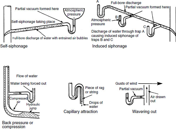
The most obvious cause of water seal loss is leakage due to defective fittings or poor workmanship. Otherwise, it may be caused by poor system design and/or installation:
Self-siphonage – as an appliance discharges, the water fills the waste pipe and creates a vacuum to draw out the seal. Causes are a waste pipe that is too long, too steep or too small in diameter.
Induced siphonage – the discharge from one appliance draws out the seal in the trap of an adjacent appliance by creating a vacuum in that appliance’s branch pipe. Causes are the same as for self-siphonage, but most commonly a shared waste pipe that is undersized. Discharge into inadequately sized stacks can have the same effect on waste branch appliances.
Back pressure – compression occurs due to resistance to flow at the base of a stack. The positive pressure displaces water in the lowest trap. Causes are a too small radius bottom bend, an undersized stack or the lowest branch fitting too close to the base of the stack.
Capillary action – a piece of rag, string or hair caught on the trap outlet.
Wavering out – gusts of wind blowing over the top of the stack can cause a partial vacuum to disturb water seals.
Resealing and Anti-siphon Traps
Where trap water seal loss is apparent, the problem may be relieved by fitting either a resealing or an anti-siphon trap. A number of proprietory trap variations are available, some of which include:
McAlpine trap – this has a reserve chamber into which water is retained as siphonage occurs. After siphonage, the retained water descends to reseal the trap.
Grevak trap – contains an anti-siphonage pipe through which air flows to break any siphonic action.
Econa trap – contains a cylinder on the outlet into which water flows during siphonic action. After siphonage the water in the cylinder replenishes the trap.
Anti-siphon trap – as siphonage commences, a valve on the outlet crown opens, allowing air to enter. This maintains normal pressure during water discharge, preventing loss of water seal.
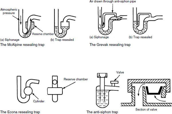
Note: Resealing and anti-siphon traps will require regular maintenance to ensure they are functioning correctly. They can be noisy in use.
This compact device has been developed by Hepworth Building Products for use on all sanitary appliances with a 32 or 40mm nominal diameter outlet. Unlike conventional water seal traps it is a straight section of pipe containing a flexible tubular sealed membrane. This opens with the delivery of waste water and fresh air into the sanitary pipework, resealing or closing after discharge. System design is less constrained, as entry of fresh air into the waste pipework equalises pressures, eliminating the need for traps with air admittance/anti-siphon valves on long waste pipe lengths.

No siphonage with full-bore discharge.
Full-bore discharge provides better cleansing of pipework.
Smaller diameter waste pipes possible as there is no water seal to siphon.
Anti-siphon and ventilating pipes are not required.
Ranges of appliances do not need auxiliary venting to stacks.
No maximum waste pipe lengths or gradients (min. 18mm/m).
Space saving, i.e. fits unobtrusively within a basin pedestal.
Tight radius bends will not affect performance.
In many situations will provide a saving in materials and installation time.
Note: Manufacturers state compliance with British Standard Codes of Practice and Building Regulations, Approved Documents for drainage and waste disposal.
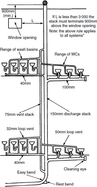
The single-stack system was developed by the Building Research Establishment during the 1960s, as a means of simplifying the extensive pipework previously associated with above-ground drainage. The concept is to group appliances around the stack with a separate branch pipe serving each. Branch pipe lengths and falls are constrained. Initially the system was limited to five storeys, but applications have proved successful in high-rise buildings of over 20 storeys. Branch vent pipes are not required unless the system is modified. Lengths and falls of waste pipes are carefully selected to prevent loss of trap water seals. Water seals on the waste traps must be 75mm (50mm bath and shower).
Branch pipe slope or fall: Sink and bath – 18 to 90 mm/m
Basin and bidet – 20 to 120mm/m
WC – 18 to 90mm/m.
The stack should be vertical below the highest sanitary appliance branch. If an offset is unavoidable, there should be no connection within 750mm of the offset.
The branch bath waste connection must be at least 200mm below the centre of the WC branch to avoid cross-flow. This may require a 50mm nom. dia. parallel pipe to offset the bath waste pipe, or an ‘S’ trap WC to offset its connection.
The vent part of the stack may reduce to 75mm nom. dia. when it is above the highest branch.

Single-stack System – Modified
If it is impractical to satisfy all the requirements for waste pipe branches in a standard single-stack system, some modification is permitted in order to maintain an acceptable system performance:
Appliances may be fitted with resealing or anti-siphon traps (see page 418).
Branch waste pipes can be ventilated (see pages 423 and 424).
Larger than standard diameter waste pipes may be fitted.

Note: Where larger than standard branch pipes are used, the trap size remains as standard. Each trap is fitted with a 50mm tail extension before connecting to a larger waste pipe.
Refs. Building Regulations, Approved Document H1, Section 1: Sanitary pipework.
BS EN 12056: Gravity drainage systems inside buildings (in five parts).
Collar Boss Single-stack System
The collar boss system is another modification to the standard single-stack system. It was developed by the Marley company for use with their uPVC pipe products. The collar is in effect a gallery with purpose-made bosses for connection of waste pipes to the discharge stack without the problem of cross-flow interference. This simplifies the bath waste connection and is less structurally disruptive.
Small-diameter loop vent pipes on (or close to) the basin and sink traps also connect to the collar. These allow the use of ‘S’ traps and vertical waste pipes without the possibility of siphonage, even when the bath waste discharges and flows into the combined bath and basin waste pipe. Vertical outlets are also likely to be less obtrusive and less exposed than higher level ‘P’ trap waste pipes.

If the branch waste pipes are kept to minimal lengths, the loop vents may not be required. However, the system must be shown to perform adequately under test without the loss of trap water seals.
All pipe sizes shown are nominal inside diameter. There may be some slight variation between different product manufacturers, particularly those using outside diameter specifications. Note that there is not always compatibility between different manufacturers’ components.
The ventilated stack system is used in buildings where close grouping of sanitary appliances occurs – typical of lavatories in commercial premises. The appliances need to be sufficiently close together and limited in number not to be individually vented.
Requirements –
WCs:
Eight maximum 100mm branch pipe 15m maximum length Gradient between 9 and 90mm/m (θ = 90½° − 95°).
Basins:
Four maximum 50 mm pipe 4m maximum length Gradient between 18 and 45mm/m (θ = 91° – 92½°).
Urinals (bowls):
Five maximum 50 mm pipe Branch pipe as short as possible Gradient between 18 and 90mm/m.
Urinals (stalls):
Seven maximum 65mm pipe Branch pipe as for bowls.

All pipe sizes nominal inside diameter.
The fully vented one-pipe system is used in buildings where there are a large number of sanitary appliances in ranges, e.g. factories, schools, offices and hospitals.
The trap on each appliance is fitted with an anti-siphon or vent pipe. This must be connected within 300 mm of the crown of the trap.
Individual vent pipes combine in a common vent for the range, which is inclined until it meets the vertical vent stack. This vent stack may be carried to outside air or it may connect to the discharge stack at a point above the spill-over level of the highest appliance.
The base of the vent stack should be connected to the discharge stack close to the bottom rest bend to relieve any compression at this point.
Size of branch and stack vents:
Discharge pipe or stack (D) (mm) |
Vent pipe (mm) |
|---|---|
<75 |
0.67D |
75–100 |
50 |
>100 |
0.50D |
All pipe sizes nominal inside diameter.
*Building Regulations Approved Document H. Section 1, Sanitary pipework.
This system was devised to comply with the old London County Council requirements for connection of soil (WC and urinal) and waste (basin, bath, bidet, sink) appliances to separate stacks. For modern systems the terms soil and waste pipes are generally replaced by the preferred terminology, discharge pipes and discharge stacks.
There are many examples of the two-pipe system in use. Although relatively expensive to install, it is still permissible and may be retained in existing buildings that are the subject of refurbishment.
It may also be used where the sanitary appliances are widely spaced or remote and a separate waste stack is the only viable method for connecting these to the drain.
A variation typical of 1930s dwellings has first-floor bath and basin wastes discharging through the wall into a hopper. The waste stack from this and the ground-floor sink waste discharge over a gully.

A gully may be used as an alternative to a rest bend before the drain.
Small Bore Pumped Waste System
These systems are particularly useful where sanitary appliance location is impractical, relative to the existing discharge pipework and stack, e.g. loft conversions and basements. The macerator, pump and small diameter discharge pipe are fairly compact, and unlikely to cause structural disruption on the scale of modifications to a conventional gravity flow system.
There are a variety of proprietary pumping systems, most capable of delivering WC and basin discharge over 20m horizontally and 4m vertically. Only products that have been tested and approved by the European Organisation for Technical Approvals (EOTA) or their recognised members (e.g. British Board of Agrément (BBA)) are acceptable for installation under the Building Regulations.
Installation is at the discretion of the local water and building control authorities. They will not accept the permanent connection of a WC to a macerator and pump, unless there is another WC connected to a gravity discharge system within the same building.
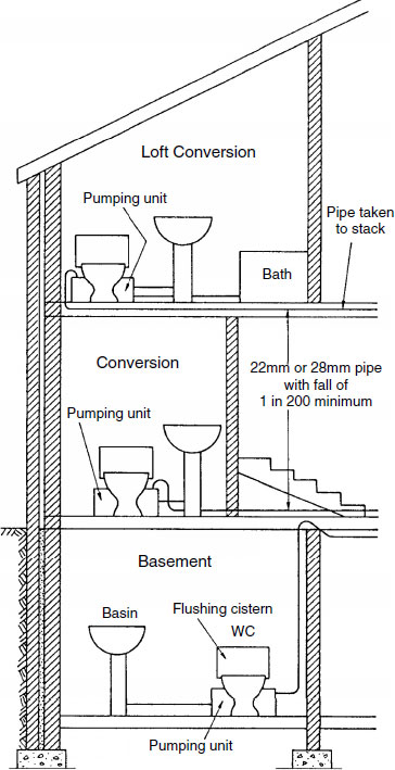
Pipework may be in 22 or 28mm outside diameter copper tube or equivalent in stainless steel or polypropylene. Easy bends, not elbow fittings, must be deployed at changes in direction.
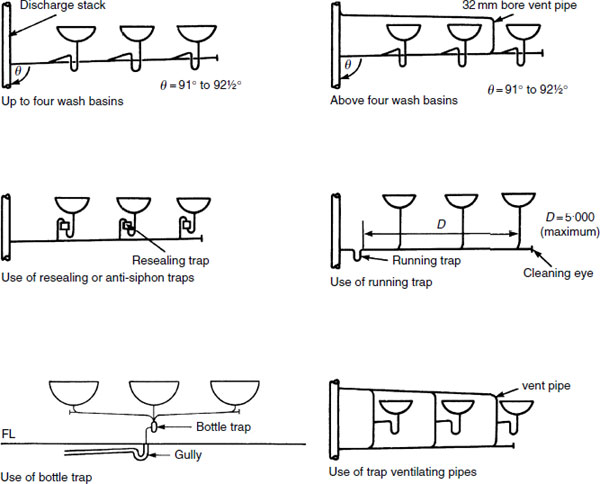
Wash Basins – Waste Arrangements
The arrangement of waste and vent pipes for ranges of basins depends upon the type of building and the number of basins in the range. See BS 6465–1: Sanitary installations. Code of practice for scale of provision, selection and installation of sanitary appliances, to determine exact requirements for different purpose groups of building.
For ranges of up to four basins, branch ventilating pipes are not necessary, providing that the inside diameter of the main waste pipe is at least 50mm and its slope is between 1° and ![]() (18mm to 45mm/m).
(18mm to 45mm/m).
For ranges above four basins, the inside diameter and slope is the same, but a 32 mm nominal inside diameter vent pipe is required. Alternatively, resealing or anti-siphon traps may be used.
In schools and factories a running trap may be used, providing that the length of main waste pipe does not exceed 5 m. Alternatively, the wastes may discharge into a glazed channel with a trapped gully outlet to the stack.
For best-quality installation work, all traps may be provided with a vent or anti-siphon pipework.
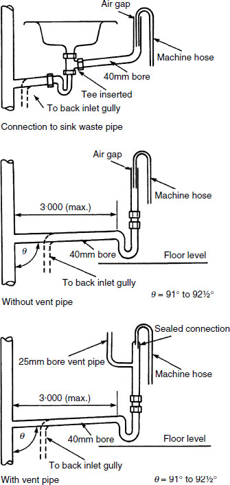
Waste Pipes from Washing Machines and Dishwashers
The simplest method for discharging the hose-pipe from a washing machine or dishwasher is to bend the hose-pipe over the rim of the sink. However, this is unattractive and may be inconvenient if the hose-pipe creates an obstruction. A more discrete and less obtrusive arrangement is to couple the hose to a tee fitting or purpose-made adaptor located between the trap and waste outlet of the sink. If a horizontal waste pipe is required at low level behind kitchen fitments, it must be independently trapped and some provision must be made for the machine outlet to ventilate to atmosphere (a purpose-made vent must not be connected to a ventilating stack). Alternatively, the machine hose-pipe may be inserted loosely into the vertical waste pipe, leaving an air gap between the two pipes.
Air Test on Sanitary Pipework Systems
Approved Document H1 to the Building Regulations provides guidance on an acceptable method for determining airtightness of sanitary pipework systems. Installations must be capable of withstanding an air or smoke test pressure at least equal to a 38 mm head of water for a minimum of three minutes. Smoke testing is not recommended for use with uPVC pipework.
Equipment for the air test:
Manometer (‘U’ gauge), rubber tube, hand bellows and two drain plugs or stoppers.
Procedure:
Stoppers are inserted at the top and bottom of the discharge stack. Each stopper is sealed with water, the lower seal with a flush from a WC. Traps to each appliance are primed to normal depth of seal. The rubber tube connected to the manometer and bellows is passed through the water seal in a WC. Hand bellows are used to pump air into the stack until the manometer shows a 38 mm water displacement. After a few minutes for air temperature stabilisation, the water level in the manometer must remain stationary for three minutes. During this time, every trap must maintain at least 25 mm of water seal.

Appliances:
Fitment |
Capacity (l) |
Discharge flow rate (l/s) |
|---|---|---|
Basin |
6 |
0.6 |
Basin – spray tap |
– |
0.06 |
Bath |
80 |
1.1 |
Shower |
– |
0.1 |
Sink |
23 |
0.9 |
Urinal |
45 |
0.15 |
Washing machine |
180 |
0.7 |
Water closet |
6 |
2.3 |
All appliances in a dwelling are unlikely to be used simultaneously, therefore the flow rate that stacks and drains have to accommodate is not the summation of their respective discharges. Allowing for normal usage, the anticipated flow rates from dwellings containing one WC, one bath, one or two wash basins and one sink are as follows:
Flow rates per dwelling:
No. of dwellings |
Flow rate (l/s) |
|---|---|
1 |
2.5 |
5 |
3.5 |
10 |
4.1 |
15 |
4.6 |
20 |
5.1 |
25 |
5.4 |
30 |
5.8 |
Discharge stack sizes:
Min. stack size (nom. i.d.) |
Max. capacity (l/s) |
|---|---|
50 |
1.2 |
65 |
2.1 |
75 |
3.4 |
90 |
5.3 |
100 |
7.2 |
Stacks serving urinals, not less than 50mm.
Stack serving one or more washdown WCs, not less than 100mm.
If one siphonic WC with a 75mm outlet, stack size also 75mm.
Trap and pipe nom. i.d. (mm) |
Trap water seal (mm) |
|
|---|---|---|
Basin |
32 |
75 |
Bidet |
32 |
75 |
Bath |
40 |
75* |
Shower |
40 |
75* |
Sink |
40 |
75* |
Dishwasher |
40 |
75 |
Washing machine |
40 |
75 |
Domestic food waste disposal unit |
40 |
75 |
Commercial food waste disposal unit |
50 |
75 |
Urinal bowl |
40 |
75 |
Urinal bowls (2–5) |
50 |
75 |
Urinal stalls (1–7) |
65 |
50 |
WC pan – siphonic |
75 |
50‡ |
WC pan – washdown |
100† |
50‡ |
Slop hopper |
100† |
50‡ |
* 38mm if discharging to a gully.
†Nominally 100mm but approx. 90mm (min. 75mm).
‡Tap integral with fitment.
Bath and shower trays may be fitted with 50mm seal traps. The following materials are acceptable for sanitary pipework:
Application |
Material |
Standard |
|---|---|---|
Discharge pipes and stacks |
Cast iron |
BS 416–1 and BS EN 877 |
Copper |
BS ENs 1254 and 1057 |
|
Galv. Steel |
BS 3868 |
|
uPVC |
BS EN 1329–1 |
|
Polyethylene |
BS 1519–1 |
|
Polypropylene |
BS EN 1451–1 |
|
MuPVC |
BS 5255 |
|
ABS |
BS EN 1455–1 |
|
PVC − C |
BS EN 1566–1 |
|
San + PVC |
BS EN 1565–1 |
Offsets have two interpretations:
Branch waste or discharge pipe connections to the discharge stack. Typically the 200mm offset required for opposing bath and WC discharge pipes – see page 420. Additional requirements are shown below.
Stack offsets – to be avoided, but may be necessary due to the structural outline of the building to which the stack is attached. Large radius bends should be used and no branch connections are permitted within 750mm of the offset in buildings up to three storeys. In buildings over three storeys a separate vent stack may be needed. This is cross-vented to the discharge stack above and below the offset to relieve pressure. Bends and offsets are acceptable above the highest spill-over level of an appliance. They are usually necessary where external stacks avoid eaves projections.
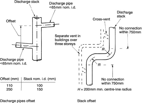
Note: Discharge stacks may be located internally or externally to buildings up to three storeys. Above three storeys, stacks should be located internally.
Ground-floor Appliances – High-rise Buildings
Lowest discharge pipe connection to stack:
Up to three storeys – 450mm min. from stack base (page 420).
Up to five storeys – 750mm min. from stack base (page 423).
Above five storeys, the ground-floor appliances should not connect into the common stack, as pressure fluctuations at the stack base could disturb the lower appliance trap water seals. Above 20 storeys, both ground- and first-floor appliances should not connect into the common stack. Ground- and first-floor appliances so affected can connect directly to a drain or gully, or be provided with a stack specifically for lower level use.

Access – required for clearing blockages. Rodding points should be fitted at the ends of discharge pipes, unless trap removal provides access to the full pipe length. Discharge stacks are accessed from the top and through access plates located midway between floors at a maximum spacing of three storeys apart.
For fire protection and containment purposes, the Building Regulations divide parts or units within buildings into compartments. A typical example is division of a building into individual living units, e.g. flats. The dividing compartment walls and floors have fire resistances specified in accordance with the building size and function.
Where pipes penetrate a compartment interface, they must have a means of preventing the spread of fire, smoke and hot gases through the void they occupy. Non-combustible pipe materials may be acceptably sealed with cement and sand mortar, but the most vulnerable are plastic pipes of low heat resistance. The void through which they pass can be sleeved in a non-combustible material for at least 1m each side. One of the most successful methods for plastic pipes is to fit an intumescent collar at the abutment with, or within, the compartment wall or floor. Under heat, these become a carbonaceous char, expand and compress the warm plastic to close the void for up to four hours.

Ref. Building Regulations, Approved Document B3: Internal fire spread (structure).
Note: See also page 661.
Sanitation Flow Rate – Formula
Simultaneous demand process – considers the number of appliances likely to be used at any one time, relative to the total number installed on a discharge stack.
Formula:

Commercial premises (e.g. offices, factories, etc.) ρ = 10 ÷ 600 = 0·017.
Public premises (e.g. cinemas, stadiums, etc.) ρ = 10 ÷ 300 = 0·033.
E.g. an office building of ten floors with four WCs, four urinals, four basins and one sink on each floor.
Total number of appliances (n) = 13 × 10 floors = 130
Substituting factors for p and n in the formula:

Flow rates (see page 430):
Four WCs at 2·3 l/s |
= 9·2 |
Four urinals at 0·15 l/s |
= 0·6 |
Four basins at 0·6 l/s |
= 2·4 |
One sink at 0·9 l/s |
= 0·9 |
Total per floor |
= 13·1 l/s |
Total for ten floors |
= 131 l/s |
Allowing 4·5% simultaneous demand = 131 × 4·5% = 5·9 l/s.
Sanitation Flow Rate – Discharge Units
The use of discharge units for drain and sewer design is shown on pages 366 and 367. The same data can be used to ascertain the size of discharge stacks and pipes.
Using the example from the previous page:
Four WCs at 14 DUs |
= 56 |
Four urinals at 0.3 DUs |
= 1·2 |
Four basins at 3 DUs |
= 12 |
One sink at 14 DUs |
= 14 |
Total per floor |
= 83·2 |
Total for ten floors |
= 832 discharge units |
Discharge units can be converted to flow in litres per second from the chart:

From the chart, a total loading of 832 discharge units can be seen to approximate to 5·5 l/s. A fair comparison with the 5·9 l/s calculated by formula on the preceding page.
Sanitation Design – Discharge Stack Sizing
Formula:
![]()

Transposing the formula to make d the subject:

Discharge units on stacks:
Discharge stack nom. i.d. (mm) |
Max. no. of DUs |
|---|---|
50 |
20 |
65 |
80 |
75 |
200 |
90 |
400 |
100 |
850 |
150 |
6400 |
Using the example from the preceding page, 832 discharge units can be adequately served by a 100 mm diameter stack.
Discharge units on discharge branch pipes:
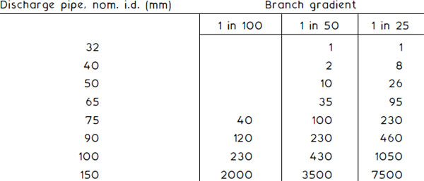
Ref. BS EN 12056–2: Gravity drainage systems inside buildings.
Sanitary pipework, layout and calculation.
Sanitation and Drainage Design Using ‘K’ Factors
The discharge unit method of stack and drain design shown on the preceding pages has limitations where a building or group of buildings are of mixed occupancy, e.g. a hotel containing bedrooms, offices, commercial kitchens, etc. In these situations there are different frequencies of appliance use.
The ‘K’ factor method is very adaptable. It uses a peak design flow coefficient. This allows for frequency of appliance use, applied to the total possible disposal from all stack or drain connected appliances.
Comparison with discharge units (see page 366):
Application |
Discharge unit time interval (min.) |
‘K’ factor coefficient |
|---|---|---|
Domestic |
20 |
0·5 |
Commercial |
10 |
0·7 |
Peak/public/congested |
5 |
1·0 |
Example based on a mixed occupancy application to a single building, containing 60 private apartments and offices:
Each apartment:
Appliances |
Disposal based on flow (see page 430) |
Two WCs |
4·6 (2 × 2·3) |
One sink |
0·9 |
Two basins |
1·2 (2 × 0·6) |
One shower |
0·1 |
One bath |
1·1 |
One washing machine |
0·7 |
One dishwasher |
0·2 |
8·8 × 60 apartments = 528 |
Offices:
Appliances |
Disposal based on flow (see page 430) |
|
|---|---|---|
Gents: |
Four WCs |
9·2 (4 × 2·3) |
Eight urinals |
1·2 (8 × 0·15) |
|
Six basins |
3·6 (6 × 0·6) |
|
Ladies: |
Ten WCs |
23·0 (10 × 2·3) |
Ten basins |
6·0 (10 × 0·6) |
|
Kitchen: |
Two sinks |
1·8 (2 × 0·9) |
44·8 |
‘K’ factors: Apartments (domestic) = 0·5 |
Offices (commercial) = 0·7 |
To allow for intermittent use of appliances, the following design formula is applied to calculate flow (Q) in litres/second:
![]()
Before calculating the flow, an adjustment is needed to the lesser figure to represent its proportional disposal. This is achieved by applying a conversion factor from the lesser to the greater flow:
Lesser flow |
Greater flow |
‘K’ conversion factor |
|---|---|---|
Domestic |
Commercial |
0·5 – 0·7 = 0·714 |
Domestic |
Peak/public/congested |
0·5 – 1·0 = 0·5 |
Commercial |
Domestic |
0·7 – 0·5 = 1·4 |
Commercial |
Peak/public/congested |
0·7 – 1·0 = 0·7 |
Peak/public/congested |
Domestic |
1·0 – 0·5 = 2·0 |
Peak/public/congested |
Commercial |
1·0 – 0·7 = 1·428 |
In this example the lesser disposal is from the offices, i.e. 44·8. The commercial – domestic converter is 1·4, therefore 44·8 × 1·4 = 62·72. Adding this to the greater domestic disposal of 528 gives a total of 590·72.
Formula application using the ‘K’ factor for the greater disposal:
![]()
Stack design formula from page 437. Taking Q = q.
![]()
Note: Do not confuse K in the formula with ‘K’ factor. K in the formula is a constant of 32 × 10−6
Therefore, ![]() , i.e. 150mm nom. dia. stack.
, i.e. 150mm nom. dia. stack.
Drain design formula from page 365. Q = V × A
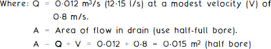
Total area of drain-pipe = 2 × 0·015 = 0·030m2

![]()
Nearest available standard drain pipe above 196mm is 225mm.
Refs. BS EN 12056–2: Gravity drainage systems inside buildings.
BS EN 752: Drain and sewer systems outside buildings.