
10 Gas Installation, Components and Controls
Properties of natural gas are considered on page 229. Some further features include:
Ignition temperature, 700°C.
Stoichiometric mixture – the quantity of air required to achieve complete combustion of gas. For combustion, the ratio of air volume to natural gas volume is about 10.6:1. Therefore, about 10% gas to air mixture is required to achieve complete combustion. As air contains about 20% oxygen, the ratio of oxygen to gas is approximately 2:1. Developing this a little further – natural gas is about 90% methane, therefore:

1 part methane + 2 parts oxygen = 1 part carbon dioxide + 2 parts water.
If there is insufficient air supply to a gas burner, incomplete combustion will result. This produces an excess of carbon monoxide in the flue; a toxic and potentially deadly gas.
Products of complete combustion – water vapour, carbon dioxide and the nitrogen already contained in the air. Correct combustion can be measured by simple tests to determine the percentage of carbon dioxide in flue gases. The Draeger and Fyrite analysers shown on page 484 are suitable means for this assessment.
Flues – these are necessary to discharge the products of combustion safely and to enhance the combustion process. The application of flues is considered in more detail later in this chapter. Flue size is normally to the boiler manufacturer’s recommendations. The principles for determining the correct flue area and length, with regard to efficient fuel combustion and avoidance of condensation in the flue, are provided on pages 491 to 493. Some gas appliances such as small water heaters and cookers are flueless. Provided they are correctly installed, they will produce no ill-effects to users. The room in which they are installed must be adequately ventilated, otherwise the room air could become vitiated (oxygen depleted). For a gas cooker, this means an openable window or ventilator. A room of less than 10 m 3 requires a permanent vent of 5000 mm2.
BG Group Plc (formerly British Gas Plc) supply gas to communities through a network of mains, installed and maintained by National Grid Transco (National Grid Plc). Gas marketing and after-sales services are provided by a number of commercial franchisees for the consumer’s choice.
Some of the underground service pipes have been in place for a considerable time. These are manufactured from steel and although protected with bitumen, PVC or grease tape (Denso), they are being progressively replaced with non-corrosive yellow uPVC for mains and polyethylene for the branch supplies to buildings. The colour coding provides for recognition and to avoid confusion with other utilities in future excavation work.
Mains gas pressure is low compared with mains water. It is unlikely to exceed 75mbar (750mm water gauge or 7.5kPa) and this is reduced by a pre-set pressure governor at the consumer’s meter to about 20mbar.
A service pipe of 25mm nominal bore is sufficient for normal domestic installations. For multi-installations such as a block of flats, the following can be used as a guide:
Nominal bore (mm) |
No. of flats |
|---|---|
32 |
2–3 |
38 |
4–6 |
50* |
>6 |
* Note: Supplies of 50mm nom. bore may be provided with a service valve after the junction with the main. Where commercial premises are supplied and the risk of fire is greater than normal (e.g. a garage), a service pipe valve will be provided regardless of the pipe size and its location will be clearly indicated. Pipes in excess of 50mm nom. bore have a valve fitted as standard.
Gas mains should be protected by at least 375mm ground cover (450mm in public areas).
Refs. The Energy Act.
The Gas Act.
The Gas Safety (Installation and Use) Regulations.
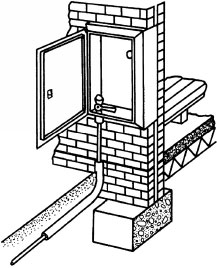
The details shown below represent two different established installations. Some of these may still be found, but unless there are exceptional circumstances the meter is no longer located within a building. An exception may be a communal lobby to offices or a block of flats. The preferred meter location for the convenience of meter readers and security of building occupants is on the outside of a building. This can be in a plastic cupboard housing on the external wall or in a plastic box with hinged lid sunken into the ground at the building periphery.

Prior to conversion to natural gas in the 1960s, a condensate receiver was used to trap moisture from town or coal gas where it was impractical to incline the service pipe back to the main.
A service pipe is the term given to the pipe between the gas main and the primary meter control. A polyethylene pipe is used underground and steel or copper pipe where it is exposed. Wherever possible, the service pipe should enter the building on the side facing the gas main. This is to simplify excavations and to avoid the pipe having to pass through parts of the substructure which could be subject to settlement. The service pipe must not:
pass under the base of a wall or foundations to a building
be installed within a wall cavity or pass through it except by the shortest possible route
be installed in an unventilated void space – suspended and raised floors with cross-ventilation may be an exception
have electrical cables taped to it
be near any heat source.

Ref. BS 8499: Specification for domestic gas meter boxes and meter bracket.
Where there is insufficient space or construction difficulties preclude the use of an external meter box or external riser, with certain provisions, the service pipe may be installed under a solid concrete floor or through a suspended floor.
For a solid floor, a sleeve or duct should be provided and built into the wall to extend to a pit of approximately 300 × 300 mm plan dimensions. The service pipe is passed through the duct, into the pit and terminated at the meter position with a control valve. The duct should be as short as possible, preferably not more than 2m. The space between the duct and the service pipe is sealed at both ends with mastic and the pit filled with sand. The floor surface is made good to match the floor finish. If the floor is exposed concrete (e.g. a garage), then the duct will have to bend with the service pipe to terminate at floor level and be mastic sealed at this point.

Where a service pipe passes through a wall or a solid concrete floor, it must be enclosed by a sleeve of slightly larger diameter pipe to provide space to accommodate any building settlement or differential movement. The outside of the sleeve should be sealed with cement mortar and the space between the sleeve and service pipe provided with an intumescent (fire-resistant) mastic sealant.
If an internal meter is used, the space or compartment allocated for its installation must be well ventilated. A purpose-made void or airbrick to the outside air is adequate. The surrounding construction should be of at least 30 minutes’ fire resistance. In commercial and public buildings the period of fire resistance will depend on the building size and purpose grouping.

Ref. Building Regulations, Approved Document B: Fire safety.
Gas Service Pipe in Multi-storey Buildings
Gas service pipe risers must be installed in fire-protected shafts constructed in accordance with the Building Regulations, Approved Document B: Fire safety. Possible methods for constructing a shaft include:
A continuous shaft ventilated to the outside at top and bottom. In this situation a fire-protected sleeve is required where a horizontal pipe passes through the shaft wall.
A shaft which is fire stopped at each floor level. Ventilation to the outside air is required at both high and low levels in each isolated section.
Shafts are required to have a minimum fire resistance of 60 minutes and the access door or panel a minimum fire resistance of 30 minutes. The gas riser pipe must be of screwed or welded steel and be well supported throughout with a purpose-made plate at its base. Movement joints or flexible pipes and a service valve are provided at each branch.

Refs. Building Regulations, Approved Document B3: Compartmentation.
BS 8313: Code of practice for accommodation of building services in ducts.
The gas meter and its associated controls are the property of the gas authority. It should be sited as close as possible to the service pipe entry to the building, ideally in a purpose-made meter cupboard on the external wall. The cupboard should be positioned to provide easy access for meter maintenance, reading and inspection. The immediate area around the meter must be well ventilated and the meter must be protected from damage, corrosion and heat. A constant pressure governor is fitted to the inlet pipework to regulate the pressure at about 20mbar (2kPa or 200mm w.g.).
Electricity and gas meters should not share the same compartment. If this is unavoidable, a fire-resistant partition must separate them and no electrical conduit or cable should be closer than 50mm to the gas meter and its installation pipework. One exception is the earth equi-potential bond cable. This must be located on the secondary pipework and within 600 mm of the gas meter.

Gas meters measure the volume of gas in cubic feet or cubic metres consumed within a building. The discharge is converted to kilowatt-hours (kWh): 100 cubic feet or 2.83 cubic metres is approximately 31kWh, (see page 489). Some older meters have dials but these have been largely superseded by digital displays which are easier to read. There are basically four categories of meter:
Domestic credit.
Domestic prepayment.
Industrial credit.
Smart (see page 13).
Credit meters measure the fuel consumed and it is paid for after use at three-monthly billing intervals. Monthly payments can be made based on an estimate, with an annual adjustment made to balance the account. Prepayment meters require payment for the fuel in advance by means of coins, cards, keys or tokens. Tokens are the preferred method and these are purchased at energy showrooms, post offices and some newsagents. A variation known as the Quantum meter uses a card to record payment. These cards are purchased at designated outlets and can be recharged with various purchase values.
Industrial meters have flanged connections for steel pipework. Flexible connections are unnecessary due to the pipe strength and a firm support base for the meter. A bypass pipe is installed with a sealed valve. With the supply authority’s approval this may be used during repair or maintenance of the meter.
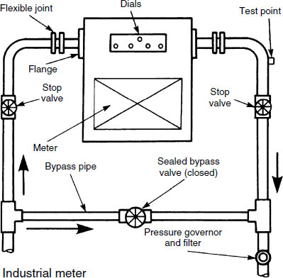
A constant pressure governor is fitted at the meter to regulate pressure into the system. It is secured with a lead seal to prevent unqualified tampering. Individual appliances may also have factory-fitted pressure governors, located just before the burners. Gas passes through the valve and also through the bypass to the space between the two diaphragms. The main diaphragm is loaded by a spring and the upward and downward forces acting upon this diaphragm are balanced. The compensating diaphragm stabilises the valve. Any fluctuation of inlet pressure inflates or deflates the main diaphragm, raising or lowering the valve to maintain a constant outlet pressure.
A meter control cock has a tapered plug which fits into a tapered body. As gas pressures are very low, the valve can operate by a simple 90° turn to align a hole in the plug with the bore of the valve body, and vice versa. The drop-fan safety cock prevents the valve from being turned accidently.

For correct combustion of natural gas, burner design must allow for the velocity of the gas-air mixture to be about the same as the flame velocity. Natural gas has a very slow burning velocity, therefore there is a tendency for a flame to lift-off the burner. This must be prevented as it will allow gas to escape, possibly exploding elsewhere! Correct combustion will occur when the gas pressure and injector bore are correct and sufficient air is drawn in, provided the gas-air velocity is not too high to encourage lift-off. Some control over lift-off can be achieved by a retention flame fitted to the burner. Flame lift-off may also be prevented by increasing the number of burner ports to effect a decrease in the velocity of the gas-air mixture. A box-type burner tray is used for this purpose.
If the gas pressure is too low, or the injector bore too large, insufficient air is drawn into the burner. This can be recognised by a smoky and unstable flame, indicating incomplete combustion and an excess of carbon monoxide. At the extreme, light-back can occur. This is where the flame passes back through the burner to ignite on the injector.

A thermostat is a temperature-sensitive device which operates a gas valve in response to a predetermined setting. Hot water heaters and boilers may be fitted with two thermostats:
Working thermostat – controls the water flow temperature from the boiler. It has a regulated scale and is set manually to the user’s convenience. It engages or disengages the gas valve at a water temperature of about 80°C.
High limit thermostat – normally preset by the boiler manufacturer to function at a water temperature of about 90°C. It is a thermal cut-out safety device which will isolate the gas supply if the working thermostat fails.
The rod-type thermostat operates by a difference in thermal response between brass and invar steel. When water surrounding a brass tube becomes hot, the tube expands. This draws the steel rod with it until a valve attached to the rod closes off the fuel supply. The reverse process occurs as the water cools.
The vapour expansion thermostat has a bellows, capillary tube and probe filled with ether. When water surrounding the probe becomes hot, the vapour expands, causing the bellows to respond by closing the fuel valve. Cooling water reverses the process.

Gas Boiler Thermostat and Relay Valve
A rod-type thermostat is often connected to a relay valve to control gas supply to the burner. When the boiler is operational, gas flows to the burner because valves A and B are open. Gas pressures above and below the diaphragm are equal. When the water reaches the required temperature, the brass casing of the rod thermostat expands and draws the invar steel rod with it to close valve A. This prevents gas from flowing to the underside of the diaphragm. Gas pressure above the diaphragm increases, allowing valve B to fall under its own weight to close the gas supply to the burner. As the boiler water temperature falls, the brass casing of the thermostat contracts to release valve A which reopens the gas supply.

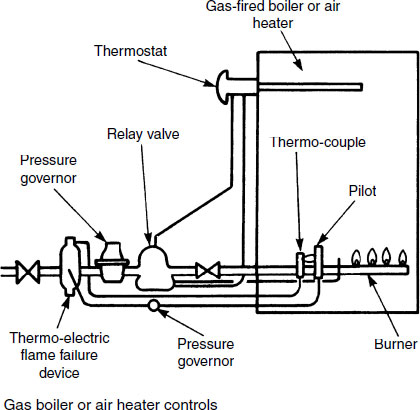
Gas water heaters/boilers and other heat-producing appliances such as air heaters must be fitted with a safety device to prevent gas from flowing in event of the pilot light extinguishing. While functional, the pilot light plays on a thermo-couple suspended in the gas flame. The hot thermo-couple energises an electromagnetic or solenoid valve to open and allow gas to flow. This is otherwise known as a thermo-electric pilot flame failure safety device. The drawing below shows the interrelationship of controls and the next page illustrates and explains the safety device in greater detail.
To commission the boiler from cold, the thermo-electric valve is operated manually by depressing a push button to allow gas flow to the pilot flame. A spark igniter illuminates the flame while the button is kept depressed for a few seconds, until the thermo-couple is sufficiently warm to automatically activate the valve. Automatic ignition of a non-permanent pilot flame is a feature of new appliances. See comment on page 457.
Ref. BS EN 483: Gas-fired central heating boilers. Type C* boilers of nominal heat input not exceeding 70kW.
* Note: Appliance types:
A Flueless
B Open flue
C Room sealed
Thermo-electric – has an ancillary thermo-couple sensing element consisting of two dissimilar metals joined together at each end to form an electrical circuit. When the thermo-couple is heated by the gas pilot flame, a small electric current is generated. This energises an electromagnet in the gas valve which is retained permanently in the open position, allowing gas to pass to the relay valve. If the pilot flame is extinguished, the thermo-couple cools and the electric current is no longer produced to energise the solenoid. In the absence of a magnetic force, a spring closes the gas valve.
Bimetallic strip – has a bonded element of brass and invar steel, each metal having a different rate of expansion and contraction. The strip is bent into a ‘U’ shape with the brass on the outside. One end is anchored and the other attached to a valve. The valve responds to thermal reaction on the strip. If the pilot flame is extinguished, the bent bimetallic strip contracts, opening to its original position and closing the gas supply and vice versa.

Lighting the pilot flame with matches or tapers is unsatisfactory. It is also difficult to effect while operating the push button control on the gas valve. An integral spark igniter is far more efficient. These are usually operated by mains electricity. An electric charge is compounded in a capacitor, until a trigger mechanism effects its rapid discharge. This electrical energy passes through a step-up transformer to create a voltage of 10 or 15kV to produce a spark. The spark is sufficient to ignite the pilot flame. Spark generation of this type is used in appliances with a non-permanent pilot flame. This is more fuel economic than a permanent flame. The spark operation is effected when the system thermostat engages an automatic switch in place of the manual push switch shown below and a gas supply to the pilot.
A piezoelectric spark igniter contains two crystals. By pressurising them through a cam-and-lever mechanism from a push button, a large electric voltage potential releases a spark to ignite the gas.

It is very important that new gas installations are thoroughly purged of air and debris that may remain in the completed pipework. This also applies to existing installations that have been the subject of significant changes. If air is not removed, it is possible that when attempting to ignite the gas, a gas-air mixture will cause a blow-back and an explosion. Before purging, the system should be pressure tested for leakages – see next page.
Procedure:
Ensure ample ventilation where gas and air will escape from the system.
Prohibit smoking, use of electrical switches, power tools, etc. in the vicinity of the process.
Close the main gas control valve at the meter.
Disconnect the secondary pipework at the furthest fitting.
Note: if the last appliance has a flame failure safety device, no gas will pass beyond it, therefore remove its test nipple screw.
Turn on the main gas control valve until the meter is completely purged.
Purging the meter is achieved by passing through it a volume of gas at least equal to five times its capacity per revolution of the meter mechanism. Most domestic meters show 0.071cu.ft. (0.002m3) per dial revolution, so: 5 × 0.071 = 0.355cu.ft. (0.010m3) of gas is required.
Turn off the main gas control valve and reconnect the open end or replace the last appliance test nipple.
Turn on the main gas control valve and purge any remaining air to branch appliances until gas is smelt.
Test any previous disconnections by applying soap solution to the joint. Leakage will be apparent by foaming of the solution.
When all the air in the system has been removed, appliances may be commissioned.
Ref. BS 6891: Installation of low-pressure gas pipework of up to 35mm in domestic premises (second family gas). Specification.
Note: For family of gases see page 229.
Testing Gas Installations for Soundness
Testing a new installation:
Cap all open pipe ends and turn appliances off.
Close the main control valve at the meter. If the meter is not fitted, blank off the connecting pipe with a specially prepared cap and test nipple.
Remove the test nipple screw from the meter or blanking cap and attach the test apparatus by the rubber tubing.
Level the water in the manometer at zero.
Pump or blow air through the test cock to displace 300mm water gauge (30mbar) in the manometer. This is approximately one and a half times normal domestic system pressure.
Wait one minute for air stabilisation, then if there is no further pressure drop at the manometer for a further two minutes the system is considered sound.
If leakage is apparent, insecure joints are the most likely source. These are painted with soap solution which foams up in the presence of air seepage.
Testing an existing system:
Close all appliance valves and the main control valve at the meter.
Remove the test nipple screw on the meter and attach the test apparatus.
Open the main control valve at the meter to record a few millimetres’ water gauge.
Close the valve immediately and observe the manometer. If the pressure rises this indicates a faulty valve.
If the valve is serviceable, continue the test by opening the valve fully to record a normal pressure of 200 to 250mm w.g. Anything else suggests that the pressure governor is faulty.
With the correct pressure recorded, turn off the main valve, allow one minute for air stabilisation and for a further two minutes there should be no pressure fluctuation.
Check for any leakages as previously described.
When used with a flexible tube, hand bellows and control cock, this equipment is suitable for measuring gas installation pressure and testing for leakage. It is also suitable for air testing drains and discharge stacks.

The glass tube is contained in a protective metal or wooden box. It is mounted against a scale graduated in millibars or millimetres. 1mbar is the pressure exerted by a 9.81mm (10mm is close enough) head of water. Water is levelled in the tube to zero on the scale. Care must be taken to note the scale calibration. Some manometers are half scale, which means the measures are in mbar or mm but they are double this to give a direct reading. Others are indirect, as shown. With these, the water displacements either side of the zero must be added.
Fires – these have a relatively low energy rating, usually no more than 3kW net input.* They are set in a fire recess and use the lined flue for extraction of burnt gases. Air from the room in older premises is usually sufficient for gas combustion, as appliances up to 7kW net input do not normally require special provision for ventilation (see page 482). Heat is emitted by convection and radiation.
Decorative fuel-effect fires – these are a popular alternative to the traditional gas fire. They burn gas freely and rely on displacement of heat by the colder air for combustion to encourage burnt gas extraction indirectly into the flue. Sufficient air must be available from a purpose-made air inlet to ensure correct combustion of the gas and extraction of burnt gases. An air-brick with permanent ventilation of at least 10000mm2 is sufficient for fires up to 12.7kW net input rating. Log- and coal-effect fires are designed as a visual enhancement to a grate by resembling a real fire, but as a radiant heater they compare unfavourably with other forms of gas heat emitters.

Ref. BS 5871: Specification for the installation and maintenance of gas fires, convector heaters, fire/back boilers and decorative fuel-effect gas appliances (in four parts).
Note: *Gas appliances are rated by maximum heat input rate (kW net). If the rating is given in kW gross, this will include a factor for latent heat of condensation in combustion.
Gas Appliances – Radiant Tube Heater
Radiant heaters – in tube format these are simple and effective heat emitters, most suited to high ceiling situations such as industrial units, warehouses and factories. They suspend above the work area and provide a very efficient downward radiation of up to 40kW. Gas is fired into one end of a tube and the combustion gases extracted by fan-assisted flue at the other. The tube may be straight or return in a ‘U’ shape to increase heat output. A polished stainless steel back plate functions as a heat shield and reflector.
The control box houses an air intake, electronic controls, gas regulators and safety cut-out mechanisms. This includes a gas isolator in the event of fan failure. To moderate burning, the end of the tube has a spiral steel baffle to maintain even temperature along the tube.
Advantages over other forms of heating include a rapid heat response, low capital cost, easy maintenance and high efficiency.

Gas Appliances – Convector Heater
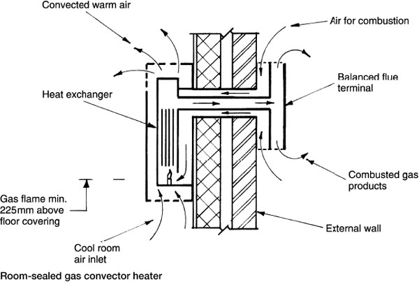
Convector – a wall-mounted, balanced flue appliance rated up to about 7kW. They are compact units, room sealed and therefore independent of natural draught from the room in which they are installed. The flue is integral with the appliance and must be installed on an external wall. An exception is when the flue is fan assisted, as this will permit a short length of horizontal flue to the outside wall.
Air for combustion of gas is drawn from outside, through a different pathway in the same terminal as the discharging combusted gases. Correct installation will ensure that the balance of air movement through the terminal is not contaminated by exhaust gases.
About 90% of the heat emitted is by convection, the remainder radiated. Some convectors incorporate a fan, so that virtually all the heat is convected.
Refs. Building Regulations, Approved Document J: Combustion appliances and fuel storage systems. Section 3 – Additional provisions for gas-burning appliances with a rated input up to 70kw (net).
The balanced flue appliance has the air inlet and flue outlet sealed from the room in which it is installed. It is more efficient than a conventional open flue pipe as there are less heat losses in and from the flue. As it is independent of room ventilation there are no draughts associated with combustion and there is less risk of combustion products entering the room. It is also less disruptive to the structure and relatively inexpensive to install.
A balanced flue is designed to draw in the air required for gas combustion from an area adjacent to where it discharges its combusted gases. These inlets and outlets must be inside a windproof terminal sited outside the room in which the appliance is installed. Gas appliances in a bath or shower room, or in a garage must have balanced flues.*

* Ref. Gas Safety (Installation and Use) Regulations.
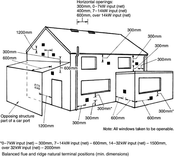
Balanced flue terminals must be positioned to ensure a free intake of air and safe dispersal of combustion products. Generally, they should be located on a clear expanse of wall, not less than 600mm from internal or external corners and not less than 300mm below openable windows, air vents, grilles, gutters or eaves.
A terminal less than 2m from ground level should be fitted with a wire mesh guard to prevent people contacting with the hot surface. Where a terminal is within 600 mm below a plastic gutter, an aluminium shield 1.5 m long should be fitted to the underside of the gutter immediately above the terminal.
Ref. Building Regulations, Approved Document J: Section 3.
Natural draught flues – appliances discharging flue gases by natural convection are located on an external wall. There must be some regard for the adjacent construction as unsatisfactory location may result in:
inefficient combustion of fuel
risk of fire
combustion products staining the wall
combustion gases entering the building.
Fan-assisted flues – appliances fitted with these can be located a short distance from an external wall. Smaller terminals are possible due to the more positive extraction of the flue gases. Terminal location is not as critical as for natural draught flues, but due regard must still be given to adjacent construction.
Location of balanced flue terminals (min. distance in mm):
Location of terminal |
Natural draught |
Fan assisted |
|---|---|---|
Directly under an openable window or a ventilator |
300* |
300 |
Under guttering or sanitation pipework |
300 |
75 |
Under eaves |
300 |
200 |
Under a balcony or a car port roof |
600 |
200 |
Horizontally to an opening window |
As ridge openings shown previous page |
300 |
Opening in a car port |
1200 |
1200 |
Horizontally from vertical drain and discharge pipes |
300 |
150 |
75 < 5 kW input (net) | ||
Horizontally from internal or external corners |
600 |
300 |
Above ground, balcony or flat roof |
300 |
300 |
From an opposing wall, other surface or boundary |
600 |
600 |
Opposite another terminal |
600 |
1200 |
Vertically from a terminal on the same wall |
1200 |
1500 |
Horizontally from a terminal on the same wall |
300 |
300 |
*See note on previous page.
Balanced Flue – Condensing Boiler
Installation must be with regard to the intrusive characteristic volume of flue gases that discharge in the form of a plume of moisture droplets. In addition to the flue location guidance given on the previous two pages, a horizontal discharge is not permitted within 2·5m of an opposing wall, a boundary fence or a neighbouring property. A vertical and/or horizontal flue pipe extension may be used to avoid these restrictions. Further, the plume should not intrude:
into a carport
over a frequently used pedestrian area, such as an access route, a patio or a terrace (see Note)
over a vehicle access route or car-parking area (see Note).
Note: An exception is where the flue discharge is at least 21m above surface or ground level.
Drainage of the condensation produced by the boiler must also be considered. The condensate can amount to as much as 4 litres in a day, and as it is slightly acid (pH 3–6, see page 21), it must be suitably disposed of. The most convenient means for disposal may be:
to a waste pipe connecting to an internal stack
into an external gully or rainwater hopper that connects to a combined drainage system
into a purpose-made soakaway.
Condensate pipes must be fitted with a water seal trap of at least 38mm depth if discharging to an open gully or rainwater hopper. The seal must be 75mm when the condensate pipe connects directly to a sanitation system waste pipe or discharge stack. The principles are as shown below.
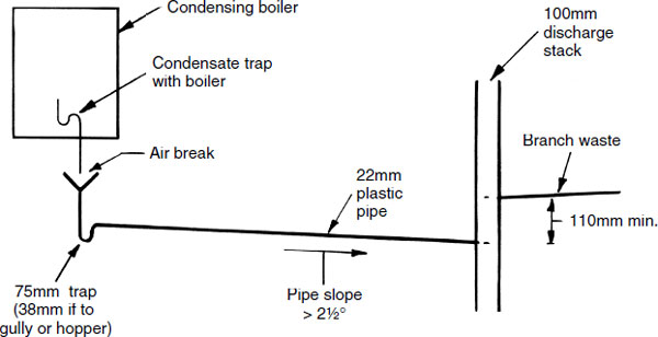
Where gravity discharge is impractical (e.g. from a boiler located in a basement), condensate may be pumped from a sump collector.
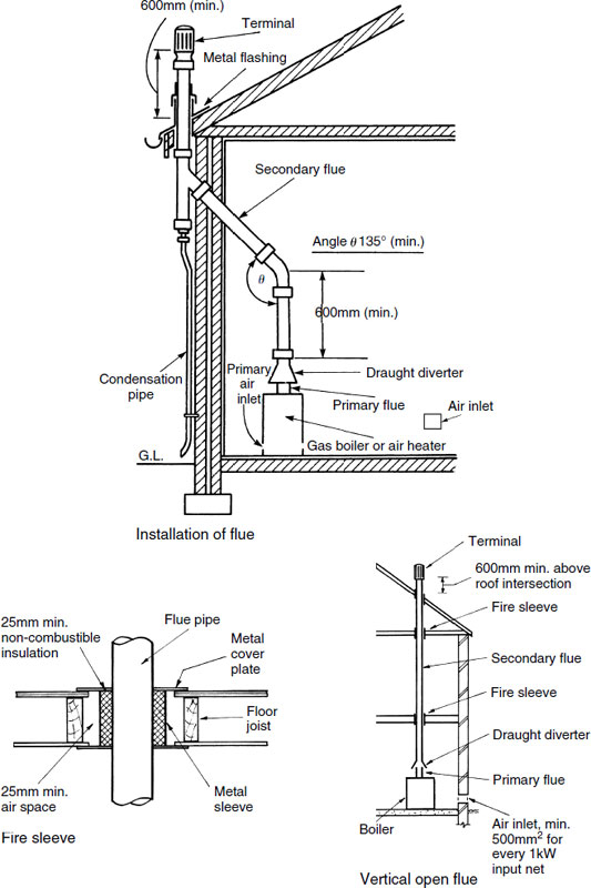
Conventional Open Flue for a Gas Burning Appliance
A gas appliance may be situated in a fire recess and the chimney structure used for the flue. The chimney should have clay flue linings to BS EN 1457: Chimneys – Clay/ceramic flue liners. A stainless steel flexible flue lining may be installed where the chimney was built before 1 February 1966, provided the lining complies with BS EN 1856-2: Chimneys. Requirements for metal chimneys. Metal flue liners and connecting flue pipes.
Other suitable flue materials include:
Pre-cast hollow concrete flue blocks, pipes made from stainless steel, enamelled steel, cast iron and fibre cement as specified in the Building Regulations (ref. below). Other products may be used that satisfy an acceptable quality standard, such as that awarded by the British Board of Agrément.
Flues must be correctly sized from appliance manufacturer’s data (see pages 491 to 493). If a flue is too large or too long, overcooling of the flue gases will produce condensation. This occurs at about 60°C when the gases cool to the dew point of water. The following factors will determine the flue size:
- heat input to the appliance
- resistance to the flow of combustion gases caused by bends and the terminal
- length of the flue.
Spigot and socket flue pipes are installed socket uppermost and joints made with fire cement. For the efficient conveyance of combusted gases, flue pipes should be vertical wherever possible. Where they pass through a floor or other combustible parts of the structure they should be fitted with a non-combustible sleeve.
A ventilation opening (air-brick) for combustion air is required in the external wall of the room containing the appliance. As a guide, for large boilers in their own plant room a ventilation-free area of at least twice the flue area is required. For domestic appliances, 500mm2 for each kilowatt of net input rating net is adequate.
Ref. Building Regulations, Approved Document J: Combustion appliances and fuel storage systems. Section 3.
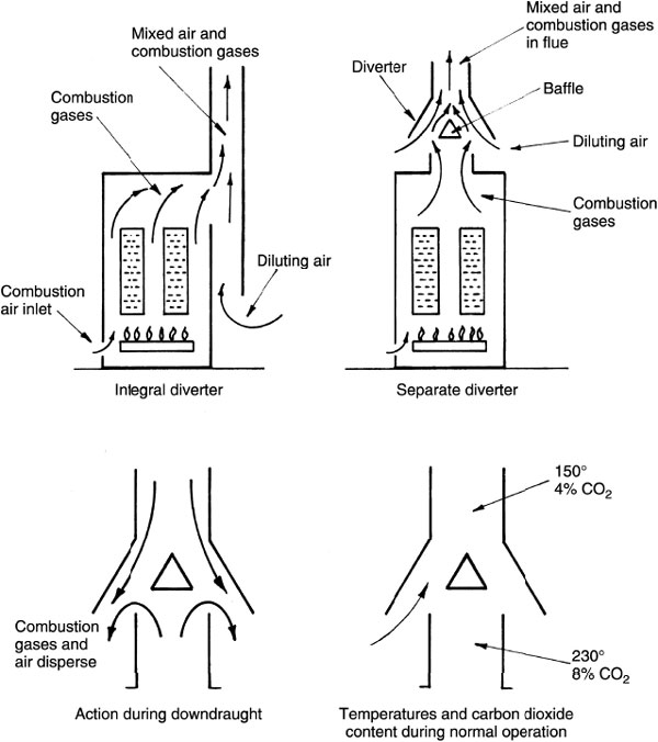
The purpose of a draught diverter is to admit diluting air into the primary flue to reduce the concentration of combustion gases and to reduce their temperature in the flue. The draught diverter, as the name suggests, also prevents flue downdraughts from extinguishing the gas pilot flame by diverting the draughts outside of the burners. Draught diverters can be provided in two ways: either as an open lower end to the flue (integral) or as an attachment (separate) to the primary flue.
Pre-cast concrete flue blocks are manufactured from high alumina cement and dense aggregates, to resist the effects of toxic flue gases and condensation. They are jointed with high alumina cement mortar and laid alternately and integrally with the inner leaf of concrete blockwork in a cavity wall. This optimises space and appearance, as there is no chimney structure projecting into the room or unsightly flue pipe. The void in the blocks is continuous until it joins a twin wall-insulated flue pipe in the roof space to terminate at ridge level.
These flue blocks are specifically for gas fires and convectors of relatively low rating. While a conventional circular flue to a gas fire must be at least 12000 mm2 cross-sectional area, these rectangular flue blocks must have a minimum flue dimension of 90mm and cross-sectional area of 16500mm2.

Ref. BS EN 1858: Chimneys. Components. Concrete flue blocks.
A flue terminal has several functions:
to prevent entry of birds, squirrels, etc.
to prevent entry of rain and snow
to resist the effects of downdraughts
to promote flue pull and extraction of combusted gases.
Location – should be with regard to positive and negative wind pressures acting on a roof to permit free wind flow across the terminal and not be too close to windows and other ventilation voids. The preferred location is at or above the ridge of a pitched roof.
Elsewhere, the following can be used as guidance:
Location |
Min. height (mm) to lowest part of outlet |
|---|---|
Within 1·5m horizontally of a vertical surface, e.g. dormer |
600 above top of structure |
Pitched roof <45° |
600 from roof intersection |
Pitched roof >45° |
1000 from roof intersection |
Flat roof |
250 from roof intersection |
Flat roof with parapet1 |
600 from roof intersection |
* Note: if horizontal distance of flue from parapet is greater than 10 × parapet height, min. flue height = 250mm.


Flat roof:
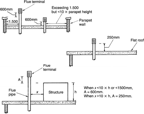
Ref. BS 5440-1: Flueing and ventilation for gas appliances of rated input not exceeding 70kW net (first, second and third family gases). Specification for installation of gas appliances to chimneys and for maintenance of chimneys.
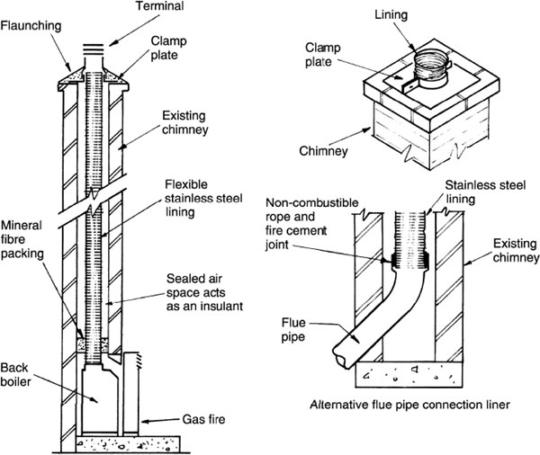
Traditional brick chimneys have unnecessarily large flues when used with gas-burning appliances. If an existing unlined chimney is to be used, a flexible stainless steel lining should be installed to prevent the combustion products and condensation from breaking down the old mortar joints. By reducing the flue area with a lining, this will accelerate the discharge of gases (efflux velocity), preventing them from lowering sufficiently in temperature to generate excessive condensation.
Coils of stainless steel lining material are available in 100, 125 and 150 mm diameters to suit various boiler connections. The existing chimney-pot and flaunching are removed to permit the lining to be lowered and then made good with a clamping plate, new flaunching and purpose-made terminal.
This is a cost-effective alternative to providing a separate flue for each gas appliance installed in a multi-storey/multi-unit building. It was originally developed by the South-east Gas Board to utilise balanced flues attached to a central ventilated void. Appliances use a central duct for air supply to the gas burners and to discharge their products of combustion. The dilution of burnt gases must be sufficient to prevent the carbon dioxide content from exceeding 1.5% at the uppermost appliance. The size of central void depends on the number of appliances connected. Tables for guidance are provided in BS 5440-1: Flueing and ventilation for gas appliances of rated input not exceeding 70kW net (first, second and third family gases). Specification for installation of gas appliances to chimneys and for maintenance of chimneys.

Note: A flame failure device is otherwise known as a flame supervision device.
The `U’ duct system is similar in concept to the Se-duct, but used where it is impractical to supply air for combustion at low level. The `U’ duct has the benefits of the Se-duct, but it will require two vertical voids which occupy a greater area. The downflow duct provides combustion air from the roof level to appliances. Appliances of the room-sealed type are fitted with a flame failure/supervision device to prevent the buildup of unburnt gases in the duct. They can only connect to the upflow side of the duct. Stable air flow under all wind conditions is achieved by using a balanced flue terminal, designed to provide identical inlet and outlet exposure. As with the Se-duct, the maximum amount of carbon dioxide at the uppermost appliance inlet must be limited to 1.5%.

Shared Flues – Concentric Duct
A metal flue system comprising a flue within a flue. A dual concentric double-wall duct or annular duct flue system uses the inner circular duct as an extract for combusted gases and the outer annular flue as a fresh air supply for fuel cumbustion. Suitable for use with several individual balanced flue appliances in apartment buildings and similar applications. A space-saving alternative to ‘U’ duct and Se-duct systems.
Maximum of 20 balanced flue appliances per shared vertical flue riser and no more than two appliances per floor.
Standard flue diameters –
Inner (mm) |
Outer (mm) |
|---|---|
150 |
285 |
180 |
340 |
200 |
375 |
250 |
470 |
00 |
565 |
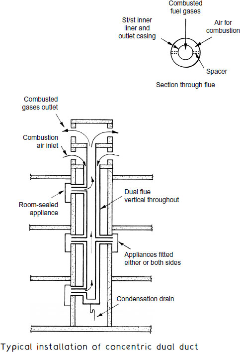
Ref. BS EN 1856-1: Chimneys. Requirements for metal chimneys. System chimney products.
Shared Flues – Shunt Duct and Branched Flues
The shunt duct system is applicable to the installation of several conventional appliances with open flues in the same building. It economises in space and installation costs when compared with providing each appliance with an individual flue. It is limited to ten consecutive storeys due to the effects of varying wind pressures and each appliance must be fitted with a draught diverter and a flame failure/supervision device. Gas fires and water heaters may be connected to this system, provided the subsidiary flue from each is at least 1.2 m and 3 m long respectively, to ensure sufficient draught.
Other shared flue situations may be acceptable where conventional open-flued appliances occupy the same room. Consultation with the local gas authority is essential, as there are limitations. An exception is the connection of several gas fires to a common flue. Also, a subsidiary branch flue connection to the main flue must be at least 600 mm long measured vertically from its draught diverter.

Note: Guidance on sizing of shared flues is provided in BS 5440-1.
With high-rise shops, office buildings and flats sharing the same boiler, problems can arise in providing a flue from ground-floor plant rooms. Instead of extending a vertical flue from ground level to the top of a building, it is possible to air dilute the flue gases and discharge them at relatively low level by installing an extract fan in the flue. As the boiler fires, the fan draws fresh air into the flue to mix with the products of gas combustion and to discharge them to the external air. The mixed combustion gases and diluting air outlet terminal must be at least 3m above ground level and the carbon dioxide content of the gases must not exceed 1%. A draught sensor in the flue functions to detect fan operation. In the event of fan failure, the sensor shuts off the gas supply to the boilers.
The plant room is permanently ventilated with air-bricks or louvred vents to ensure adequate air for combustion. Ventilation voids should be at least equivalent to twice the primary flue area.
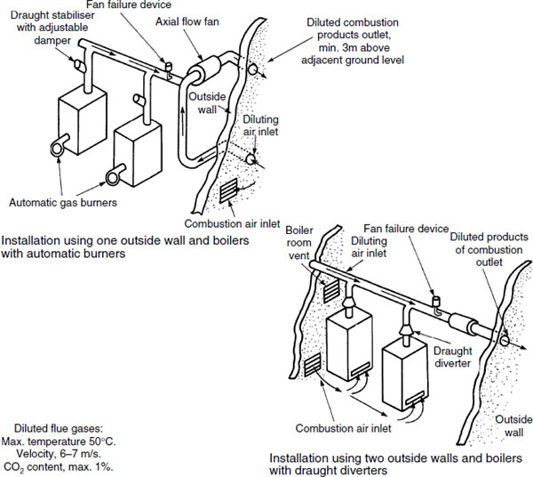
Fan assistance with the dilution and removal of combustion products has progressed from commercial and industrial applications in open flues, to domestic appliance balanced flues. In addition to diluting the CO2 content at the flue gases point of discharge, fanned draught-balanced flue systems have the following advantages over standard balanced flues:
Positive control of flue gas removal without regard for wind conditions.
Location of flue terminal is less critical – see page 466.
Flue size (inlet and outlet) may be smaller.
Flue length may be longer, therefore the boiler need not be mounted on an external wall.
Heat exchanger may be smaller due to more efficient burning of gas. Overall size of boiler is reduced.
The disadvantages are noise from the fan and the additional features could make the appliance more expensive to purchase and maintain.
I f the fan fails, the air becomes vitiated due to lack of oxygen and the flames smother. The flame failure/protection device then closes the gas valve.
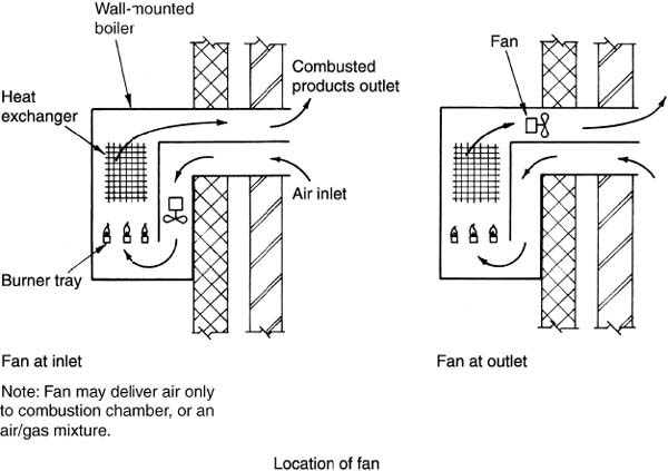
Note: Fan my deliver air only to combustion chamber, or an air/gas mixture.
Note: Fan will be specifically designed to withstand high flue gas temperatures.
Ventilation for Gas Appliances <70kW (Net) Input
Room-sealed balanced flue appliances do not require a purposemade air vent for combustion as the air supply is integral with the terminal. Where installed in a compartment or in an enclosure such as a cupboard an air vent is necessary to remove excess heat. With open or conventional flue appliances, access must be made for combustion air. This equates to at least 500mm2 of free area per kW (net), e.g. the ventilation area required for an open-flued boiler of 20kW (net) input rating will be at least 20 × 500 = 10000mm2 (see also page 483).
Conventionally flued appliances will also require air for cooling if they are installed in a compartment. This may be by natural air circulation through an air-brick or with fan enhancement. Flueless appliances such as a cooker or instantaneous water heater require an openable window direct to outside air, plus the following ventilation grille requirements:
Oven, hotplate or grill:
Room volume (m3) |
Ventilation area (mm2) |
|---|---|
<5 |
10000 |
5-1 |
5000 (non-required if a door opens directly to outside air) |
>10 |
Non-required |
Instantaneous water heater (max. input 11kW (net)):
Room volume (m3) |
Ventilation area (mm2) |
|---|---|
<5 |
not permitted |
5-1 |
10000 |
10–20 |
5000 |
>20 |
non-required |
Vents should be sited where they cannot be obstructed. At high level they should be as close as possible to the ceiling, and at low level not more than 450mm above floor level. When installed between internal walls, vents should be as low as possible to reduce the spread of smoke in the event of a fire.
Open-flued gas fires rated below 7kW (net) installed in older premises (built pre-2009) require no permanent ventilation, but decorative fuel-effect fires will require a vent of at least 10000mm2 free area.
The next page illustrates requirements for room-sealed and open-flued appliances.

Refs. Building Regulations, Approved Document J: Combustion appliances and fuel storage systems. Section 3.
* Older dwellings (built pre-2009) having air permeability >5 m3/hour per m2 at 50 Pa, the first 7kW (net) can be ignored.
Ventilation for Gas Appliances – Calculations
Calculations relate to applications shown on the preceding page.
Example 1: A conventional open-flue appliance of 12kW net input rating in an older dwelling (see note on page 461 regarding input and output ratings).
• Installed in a room.
No vent required up to 7kW, but 500mm2 to be provided per kW thereafter:
12kW – 7kW = 5kW × 500mm2 = 2500mm2 air vent area.
• Installed in a cupboard compartment open to a ventilated room.
Air vent area is the same as above.
Vent area for cooling the appliance is 1000mm2 for every kW rating:
12kW × 1000mm2 = 12000mm2
Ventilation, cooling and combustion air area:
12kW × 2000mm2 = 24000mm2.
• Installed in a compartment open to the outside.
Air for cooling the appliance is 500mm2 for every kW rating:
12kW × 500mm2 = 6000mm2.
Air for combustion:
12kW × 1000mm2 = 12000mm2.
Example 2: A room-sealed balanced flue appliance of 12kW net input rating.
• In a cupboard compartment open to a ventilated room. Air for ventilation and cooling is 1000mm2 (twice):
12kW × 1000mm2 = 12000mm2 (twice).
• In a cupboard compartment open to the outside. Air for ventilation and cooling is 500mm2 per kW (twice):
12kW × 500mm2 = 6000mm2.
Note: Provision for ventilation in walls may be partly by natural infiltration, but where this is insufficient, purpose-made air-bricks are built into the wall. These should not be obscured or covered over.
Simple field tests are available to assess the efficiency of gas combustion with regard to the percentage of carbon monoxide and carbon dioxide in the flue gases.
Draeger analyser – hand bellows, gas sampler tube and a probe. The tube is filled with crystals corresponding to whether carbon monoxide or carbon dioxide is to be measured. The probe is inserted into the flue gases and the bellows pumped to create a vacuum. The crystals absorb different gases and change colour accordingly. Colours correspond with a percentage volume.

Fyrite analyser – hand bellows, container of liquid reactant and a probe. Flue gases are pumped into the container which is inverted so that the liquid reactant absorbs the gas in solution. The liquid rises to show the percentage carbon dioxide corresponding to a scale on the container. Oxygen content can also be measured using an alternative solution.

Note: Flue gas samples can be taken by inserting the probe below the draught diverter or through the access plate on top of the appliance combustion chamber. Samples can also be taken at the terminal. The above apparatus is retained to illustrate the principles of probe testing. Modern LCD handheld units are now in general use and have the benefit of determining flue gas temperature, O2, CO and CO2 content.
Calculations relating to the storage, conveyance and combustion of gas include factors for volume, pressure and temperature at constant mass. If not restrained, gas will expand when heated and occupy more than its pre-heated volume. If constrained and the volume of gas is restricted, gas when heated will increase in pressure.
Boyle’s law – for a fixed mass of gas at constant temperature, the volume is inversely proportional to its absolute pressure.
![]()
where:
![]()
By adapting the formula it is possible to calculate the volume that gas will occupy relative to change in pressure:
![]()
where:
![]()
E.g.

![]()
P × V is always the same. E.g. for P1 = 2 and V1 = 20:
Value of P2 |
Value of V2 |
Constant sum |
|---|---|---|
4 |
10 |
40 |
8 |
5 |
.. |
10 |
4 |
.. |
20 |
2 |
.. |
Note: At normal operating pressures Boyle’s law is reasonably true, but at high pressures there is some variation.
Charles’ law – this differs from Boyle’s law by considering the effect of temperature on gas. Charles’ law states that for a fixed mass of gas at constant pressure, the volume occupied is directly proportional to the absolute or thermodynamic temperature. The proportion is 1/273 of the gas volume at 0°C for every degree rise in temperature. Therefore, if a gas at 0°C is raised to 273°C its volume will double.
Minus 273° C is absolute temperature at zero degrees Kelvin (see page 698), the theoretical point at which gas has no volume. Therefore:
![]()
where:

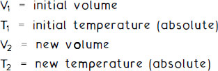
By adapting the formula it is possible to calculate the volumes occupied by the same gas at different temperatures at constant pressure:
![]()
where:
E.g. An underground service pipe containing gas at 5°C supplies a boiler room at 20°C.
![]()
Transposing Charles’ formula to make V2 the subject:
![]()
This suggests that the consumer would get some free fuel (0.054m3 for every 1m3 metered), but gas accounts usually contain a correction factor for the volume conversion.
Changes in the conditions affecting gas will normally include pressure and temperature at the same time. Therefore, if Boyle’s and Charles’ laws are combined the three conditions of volume, pressure and temperature can be represented. In this format the formula is known as the general gas law:
![]()
By adapting the general gas law formula, a gas under two different conditions can be compared:
![]()
E.g. If a consumer’s gas supply is set to 20mbar (millibars) by the meter pressure governor, it will be reduced again at an appliance pressure governor. For this example, say 5mbar.
Note: Atmospheric pressure is taken at 101.3kN/m2 or 1013mbar.
For 1 m3 initial volume of gas, Boyle’s law can be used to show the volume of gas at the reduced pressure of the appliance:
![]()
Transposing:
![]()
If the gas has a temperature of 10°C at the meter and 16°C at the appliance, the general gas law to determine the new volume (V2) of gas with regard to pressure and temperature difference can be applied:
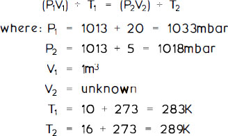
Transposing the general gas law to make V2 the subject:
![]()
The rate of gas flowing in a pipe can be calculated by applying Pole’s formula. This is a variation of the D’Arcy fluid flow formula shown on pages 78 and 79.
Pole’s formula can be expressed as:

where: 0.001978 and 0.0071 are constant friction coefficients
The second formula is usually favoured. This provides a figure compatible with gas consumed by an appliance, in m3/h.
For example, determine the gas flow rate in a 10m length of 15mm o.d. copper tube (13·5mm i.d.) with an acceptable pressure loss of 1mb.
![]()
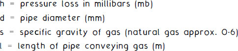
Pole’s formula can be rearranged to make pressure loss (h) the subject:
![]()
It can be seen that the pressure loss (h) is directly proportional to:
the square of the flow rate (Q)
the gas specific gravity (s)
the pipe length (l)
Pressure loss varies inversely with the fifth power of the pipe diameter (d).
If the quantity of gas is doubled, the pressure loss will increase four times, i.e. (2)2.
If the pipe length is doubled, the pressure loss will double.
If the pipe diameter is halved, the pressure loss will increase 32 times, i.e. (2)5.
Note: Pole’s formula is limited to normal low-pressure gas installations. Under higher pressure, alternative formulae which incorporate gas compressibility factors are more appropriate.
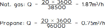
Typical natural gas consumption figures for domestic appliances:

Exact gas consumption rate (Q) can be calculated from the following formula:
![]()
Given that the calorific values for natural gas and propane (LPG) are 38 500kJ/m3 and 96 000kJ/m3 respectively, the value of Q for a 20kW input boiler is:
Operating costs – fuel tariffs can be obtained from the various gas suppliers. A typical charge for natural gas is 1.3 pence per kWh. If the 20kW input boiler consumes gas for five hours per day, the operating cost will be:
![]()
To convert gas metered in units of cubic feet, multiply by 0.0283, i.e. 1 cu. ft. = 0.0283m3.
Gas consumed in kWh:
![]()
where: 1kWh = 3.6MJ (conversion factor)
e.g. 100cu. ft at 2.83m3
![]()
To determine the size of pipework, two factors must be established:
The gas consumption (Q).
The effective length of pipework.
The effective length of pipework is taken as the actual length plus the following allowances for fittings in installations up to 28mm outside diameter copper tube:
Fitting |
Equivalent length (m) |
|---|---|
elbow |
0.5 |
tee |
0.5 |
bend (90°) |
0.3 |
The gas discharge in m3 /hour for copper tube for varying effective lengths is as follows:

This table is appropriate for 1mb (10mm w.g.) pressure drop for gas of relative density 0.6.
Example:
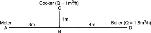
Note: |
A to B contains 3 elbows and 1 tee |
B to C contains 3 elbows | |
B to D contains 4 elbows |
Pipe A to B, gas flow = 1 m3/h + 1.6m3/h = 2.6m3/h
Actual pipe length = 3m
Effective pipe length = 3 + (3 × 0.5) + (1 × 0.5) = 5m
From the table, a 22mm o.d. copper tube can supply 2.6m3/h for up to 23.75 metres (by interpolating between 20 and 25m).
Pressure drop over only 5m will be: 5 ÷ 23.75 = 0.21mb (2.1mm w.g.).
Pipes B to C and B to D can be calculated similarly.
Ref: |
BS 6891: Installation of low-pressure gas pipework of up to 35mm in domestic premises. Specification. |
Open flue, naturally aspirated – a flue pipe equivalent to the size of the appliance outlet is generally adequate. However, some variation may be possible, but care must be taken not to undersize the flue, as this will cause a high efflux velocity and spillage of combustion products. Oversizing is uneconomical, less easy to accommodate and likely to produce condensation in the flue.
Example:

where Flue gas volume (v) per second = 410 ÷ 3600 = 0.1139m3/s
![]()
Therefore, flue diameter = 0.203m, or 203 mm (8Ø standard imperial size)
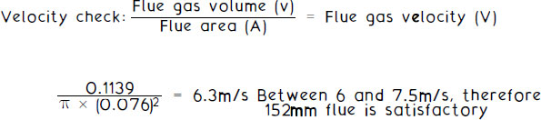
Induced draught flue – a conventional or open flue with a flue gas extract fan. Extract velocity (V) is between 6 and 7.5m/s.
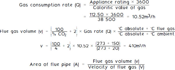
Using a 112.50kW gross input rated boiler from the example on the previous page, the gas consumption rate (Q) and flue gas volume (v) are 10.52m3/h and 410m3/h respectively.
The flue pipe diameter formula is as shown on the previous page, but with the velocity of fanned flue gases (V) increased to, say, 7m/s.
![]()
Therefore, flue diameter = 0.144m, rounded up to 152mm (6![]() standard imp. size)
standard imp. size)
Flue gas volume (v)
Fan air-diluted flue † see page 479 for installation between two side walls and for operating data. Using two of the 112.50 kW rated boilers with flue gas extract velocity (V) between 6 and 7m/s, the following formula may be used to obtain the flue gas volume (v):
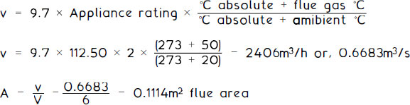
A square flue will be −/0.1114 = 334mm × 334mm
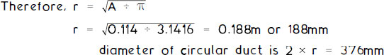
A circular flue is derived from Area(A) = nr2 where, r = radius
The foilowing formula is a guide to the minimum flue height (H) inmetres, with regard to the efficient discharge of flue gases from naturally aspirated boilers:
H = 6 × “ Boiler rating gross input in MW)06 + allowance for resistances at bends, etc.
Factors for resistance to flue gas flow can be taken as listed below:
Flue pipe component |
Resistance factor |
|---|---|
90° bend |
0.50 |
1 35° bend |
0.25 |
Vertical terminal |
0.25 |
Ridge terminal |
1 .00 |
Horizontal flue |
0.30/m |
I nclined flue (45°) |
0.13/m |
Vertical flue |
Zero |
Taking the examples shown in the previous two pages of one 112.50 kW gross input (90kW net) rated boiler. Assuming that the boiler flue is vertical with the exception of two 135° bends, one metre of 45° inclined flue and a vertical terminal, the formula for minimum flue height can be written:
![]()
Condensation within a flue system must be prevented by:
keeping the flue gas temperature as high as possible
keeping the dew point of the flue gases low
In practical terms this is achieved by:
correctly sizing the flue to avoid excessive surface areas
insulating the flue or use of double-walled, insulated flue pipes
limiting the lengths of flue systems (see graph)
