
11 Electrical Supply and Installations
Three-Phase Generation and Supply
Electricity Intake to a Building
Testing Completed Installation
Controls for Electric Night Storage Space Heaters
Three-phase Generation and Supply
In 1831 Michael Faraday succeeded in producing electricity by plunging a bar magnet into a coil of wire. This is credited as being the elementary process by which we produce electricity today, but the coils of wire are cut by a magnetic field as the magnet rotates. These coils of wire (or stator windings) have an angular spacing of 120° and the voltages produced are out of phase by this angle for every revolution of the magnets, thus generating a three-phase supply.
A three-phase supply provides 73% more power than a single-phase supply for the addition of a wire. With a three-phase supply, the voltage between two line or phase cables is 1.73 times that between the neutral and any one of the line cables, i.e. 230 volts × 1.73 = 400 volts, where 1.73 is derived from the square root of the three phases.

Note: The following section on electrical systems should be read with regard to Building Regulations, Approved Document P: Electrical safety, and BS 7671: Requirements for Electrical Installations, the IEE Wiring Regulations 17th edition.
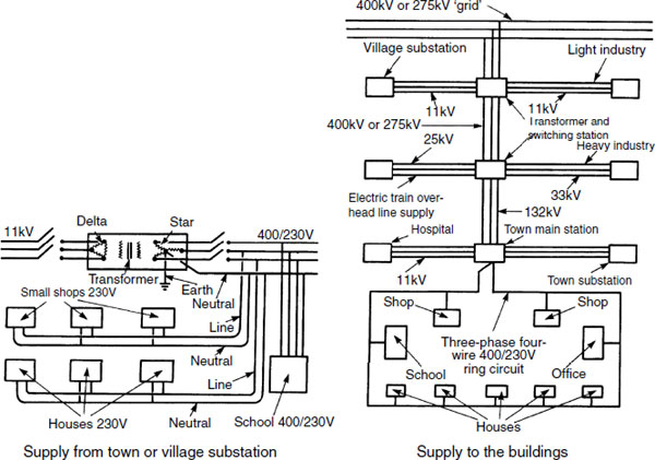
In the UK electricity is produced at power-generating stations at 25 kilovolt (kV) potential, in three-phase supply at 50 cycles per second or hertz (Hz). Thereafter it is processed by step-up transformers to 132, 275 or 400kV before connecting to the national grid. Power to large towns and cities is by overhead lines at 132kV or 33kV where it is transformed to an 11kV underground supply to substations. From these substations the supply is again transformed to the lower potential of 400 volts, three-phase supply and 230 volts, single-phase supply for general distribution.
The supply to houses and other small buildings is by an underground ring circuit from local substations. Supplies to factories and other large buildings or complexes are taken from the 132 or 33kV main supply. Larger buildings and developments will require their own transformer, which normally features a delta-star connection to provide a four-wire, three-phase supply to the building.
Note: For easy identification, each phase cable has colour-coded plastic insulation of brown (red), black (yellow) or grey (blue). The neutral is colour coded blue (black). An outer sheathing of red or black provides for future identification. Older installations will have colour codes as indicated in brackets.
Private Substation/transformer
A substation is required for the conversion, transformation and control of electrical power. It is used where large buildings or complexes of buildings require greater power than the standard low or medium potential of 230 and 400 volts. A substation must be constructed on the customer’s premises. It is supplied by high-voltage cables from the electricity authority’s nearest switching station. The requirements for a substation depend upon the number and size of transformers and switchgear.
A transformer is basically two electric windings, magnetically interlinked by an iron core. An alternating electromotive force applied to one of the windings produces an electromagnetic induction corresponding to an electromotive force in the other winding. If the number of turns in the secondary coil is reduced, the voltage is reduced and the current increased, and vice versa.

Electricity Intake to a Building
The termination and metering of services cables to buildings is determined by the electricity authority’s supply arrangements. Most domestic supplies are underground with the service cable terminating at the meter cupboard, as shown. Depth of cover to underground cables should be at least 750mm below roads and 450mm below open ground. In remote areas the supply may be overhead. Whatever method is used, it is essential that a safety electrical earthing facility is provided and these are considered on the next page. All equipment up to and including the meter is the property and responsibility of the supplier. This also includes a fusible cut-out, neutral link and in some situations a transformer. Meters are preferably sited in a purpose-made reinforced plastic compartment set in or on the external wall of a building.

Note: All domestic internal distribution systems must be undertaken by a ‘competent person’, i.e. a qualified electrician. Electrical contractors certified as competent can ‘self-certificate’ their work. Work completed by lesser qualified people must be referred to the Local Authority Building Control Department and a fee paid for inspection by their appointed qualified inspector. Minor work, such as replacing socket outlets, control switches and ceiling fittings, can be undertaken without contravention.
Ref. Building Regulations, Approved Document P: Electrical Safety.
Supply systems require a safety electrical earthing facility. The manner in which this is effected will depend on whether the supply is overhead or underground and the conductive property of the ground surrounding the installation. Systems are classified in accordance with a letter coding:
First letter – type of earthing:
T – at least one point of the supply is directly earthed.
I – the supply is not directly earthed, but connected to earth through a current limiting impedance. Not acceptable for public supplies in the UK.
Second letter – installation earthing arrangement:
T – all exposed conductive metalwork is directly earthed.
N – all exposed conductive metalwork is connected to an earth provided by the supply company.
Third and fourth letters – earth conductor arrangement:
S – earth and neutral conductors separate.
C – earth and neutral conductors combined.
Common supply and earthing arrangements are:
TT (shown below).
TN-S and TN-C-S (shown on next page).
TT system:
Most used in rural areas where the supply is overhead. An earth terminal and electrode is provided on site by the consumer. As an extra safety feature, a residual current device (RCD), generally known as a trip switch, is located between the meter and consumer unit. The RCD in this situation should be of the time-delayed type – see page 518.

TN-S system – this is widely used in the UK, with the electricity supply company providing an earth terminal with the intake cable. This is usually the metal sheathing around the cable, otherwise known as the supply protective conductor. It connects back to the star point at the area transformer, where it is effectively earthed.
TN-C-S system – this is as the TN-S system, but a common conductor is used for neutral and earth supply. The supply is therefore TN-C, but with a separated neutral and earth in the consumer’s installation it becomes TN-C-S. This system is also known as protective multiple earth (PME). The advantage is that a fault to earth is also a fault to neutral, which creates a high fault current. This will operate the overload protection (fuse or circuit-breaker) rapidly.

Note: Specification of installation cable between supply company’s sealing chamber and consumer’s unit – phase/line and neutral 25mm2, earth 16 mm2 cross-sectional area.
Pages 496, 497 and 501 show that the consumer’s earth conductor is connected to the neutral and earthed at the local transformer. For below-ground supplies this arrangement provides a path of low resistance for an electrical fault. With an overhead supply typical of rural areas, individual consumers must provide a suitable earth terminal or electrode as shown on page 500.
Unless wet, the ground surface is not usually a very good conductor, therefore ground contact is made at about 1.5 to 2m below the surface. In the past this was achieved by earth bonding to metal water and gas mains. Since the introduction of plastic pipe materials, this is of course no longer acceptable. Current practices include burying a metal plate or a metal tape mesh arranged over several square metres, or driving a metal rod electrode into the ground. The latter is normally adequate for domestic and other small-scale installations. In some instances, the electrode is housed as shown below. Whatever earth method is used, a low resistance to an electrical fault is essential. The IEE Wiring Regulations recommend that the earth electrode resistance should not exceed 200ohms.

Equipotential Bonding of Services and Extraneous Metalwork
Metal sheathed and armoured cables, earthed metal trunking, metal service pipework associated with electrical equipment and fixed structural steelwork liable to introduce a potential to be protective earthed by bonding together and connecting to earth. This ensures that no dangerous potential differences can occur as there will be a low-resistance return path to earth to promptly operate the overload protection device.

As indicated on the previous four pages, every part of an electrical installation must be earthed. This is achieved by connecting all exposed conductive parts with a circuit protective conductor (cpc) and joining this to the main earthing terminal. The cpc is usually a single core cable with distinct green and yellow insulation, although metal trunking and conduit used for cable conveyance may also function as the cpc.
Earthing provision of exposed and extraneous metal parts is shown on the preceding page. This ensures that no dangerous potential difference can occur between possible conductive parts.
Main equipotential bonding – of at least 10mm2 cross-sectional area (csa) is attached to the gas and water supplies with an earth clamp as shown on the preceding page. Connection to the gas pipe is within 600mm of the meter on the consumer ‘s side (see page 449) and above the water supply stop valve if the supply to the valve is in plastic. If the water supply pipe is metal, connection is before the valve.
Supplementary bonding – provided for fixed metalwork or extraneous conductive parts, i.e. metalwork that is not directly associated with the electrical installation but could accidentally come into contact with it and become live. This will include taps (electric immersion heater), radiator (central heating pump), window (cable through to garden), etc. All extraneous metalwork in a bathroom must be bonded.
A minimum of 4mm2 csa supplementary bonding conductor satisfies most domestic situations, but if the cpc exceeds 10mm2 csa the supplementary bonding conductor must have at least half this csa. E.g. a 16mm2 csa cpc will require 10mm2 csa supplementary bonding (6mm2 is too small and 8mm2 csa is not a standard commercially available specification). Supplementary bonding conductors of less than 16mm2 must not be of aluminium.
Ref. BS 951: Electrical earthing. Clamps for earthing and bonding. Specification.
Historically, electrical installations required a separate fuse and isolator for each circuit. Modern practice is to rationalise this into one ‘fuse box’, known as a consumer’s power supply control unit or consumer unit for short. This unit contains a two-pole switch isolator for the phase/line and neutral supply cables and three bars for the line, neutral and cpc to earth terminals. The line bar is provided with several fuse ways or miniature circuit-breakers (up to 16 in number for domestic use) to protect individual circuits from overload. Each fuse or mcb is selected with a rating in accordance with its circuit function. Traditional fuses are rated at 5, 15, 20, 30 and 45 amps while the more modern mcbs are rated in accordance with BS EN 60898: Circuit-breakers for over-current protection for household and similar installations.
Circuit |
Mcb rating (amps) |
|---|---|
Lighting |
6 |
Immersion heater |
6 or 20* |
Socket ring |
32 |
Cooker |
40 or 45* |
Shower |
40 or 45* |
* Depends on the power rating of appliance. A suitable mcb can be calculated from: Amps = Watts ÷ Voltage.
E.g. A 3kW immersion heater: Amps = 3000 ÷ 230 = 13.
Therefore a 16 amp rated mcb is adequate.

Ref. BS EN 61439–3: Low-voltage switchgear and controlgear assemblies.
A split load consumer unit provides for additional and specific protection to outgoing circuits that may supply electricity to portable equipment for use outdoors. This is particularly appropriate for ground- floor sockets that could have an extension lead attached, e.g. cooker control panel, kitchen ring final circuit and ground-floor ring final circuit.
These ground-floor circuits have a dedicated line and neutral bar within the consumer unit and an RCD (RCCB) protection device in addition to miniature circuit-breakers for each individual circuit. A typical disposition of components within a split load consumer unit is as shown.

Types of protection against residual current by residual current devices (RCDs):
RCCB – Residual current circuit-breaker. An incoming switch disconnecting device activated by an earth leakage fault – see page 518.
RCBO – Residual current circuit breaker with integral overload protection. An alternative to a miniature circuit-breaker (mcb) as an outgoing individual circuit protection device. It has a dual function, combining earth leakage protection with the current overload protection provided by an mcb.
Where an existing consumer unit is in good order but of insufficient capacity to accept additional fuseways/mcbs, replacement with a larger unit is not always necessary. It is not acceptable to connect more than one circuit to a fuseway. If there is adequate space, an additional consumer unit can be added in parallel to the existing unit. When upgrading any of the intake fitments, the electricity supply authority should be consulted to determine that their supply equipment and facility would not be overloaded, particularly where it is proposed to provide for high-powered appliances and fittings such as a cooker and/or a shower Line (phase) and neutral cable connections between meter and consumer unit(s) may need to be upgraded to 25mm2 csa and the earth conductor to 16mm2 csa.

With the intake isolated, a service connector box or splitter box is fitted to the live and neutral supply cables between the meter and the existing consumer unit. From this connection supply cables extend to the additional consumer unit. See note on page 499 regarding competence of installer.
A ring final circuit is used for single-phase power supply to three-pin sockets. It consists of PVC sheathed cable containing line and neutral conductors in PVC insulation and an exposed circuit protective conductor to earth looped into each socket outlet. In a domestic building a ring final circuit may serve an unlimited number of sockets up to a maximum floor area of 100m2. A separate circuit is also provided solely for the kitchen, as this contains relatively high rated appliances. Plug connections to the ring have small cartridge fuses up to 13 amp rating to suit the appliance wired to the plug. The number of socket outlets from a spur should not exceed the number of socket outlets and fixed appliances on the ring.
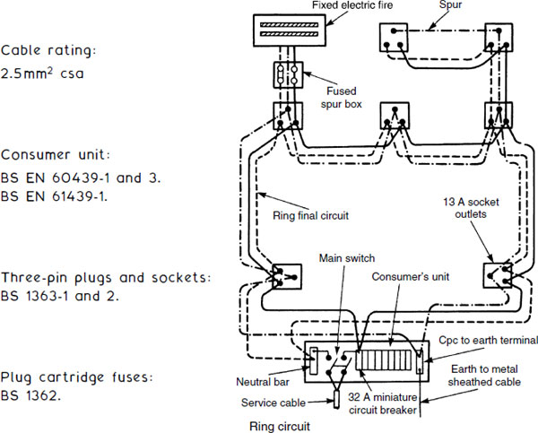
Note: Fixed appliances such as fires, heating controls and low-powered water heaters can be connected to a fused spur from a ring socket. Appliances and installations with a load factor above 3kW (e.g. immersion heater, cooker, extension to an outbuilding, etc.) must not be connected to any part of a ring final circuit. These are supplied from a separate radial circuit from the consumer unit.
Power sockets should be positioned between 150mm and 250mm above work surfaces and between 450 mm and 1200mm above floor levels. An exception is in buildings designed for the elderly or infirm, where socket heights should be between 750 and 900mm above the floor. Every socket terminal should be fitted with a double outlet to reduce the need for adaptors. Disposition of sockets would limit the need for lead lengths to no more than 2 m.
The following provides guidance on the minimum provision for power sockets in domestic accommodation:
Location |
Minimum quantity of sockets |
|---|---|
Living rooms |
8 |
Kitchen |
6 |
Master bedroom |
6 |
Dining room |
4 |
Study bedroom |
4 |
Utility room |
4 |
Single bedrooms |
4 |
Hall and landing |
2 |
Garage/workshop |
2 |
Bathroom |
1 – double-insulated shaver socket |
Maximum appliance load (watts) and plug cartridge fuse (BS 1362) selection for 230 volt supply:
Maximum load (W) |
Plug fuse rating (amp) |
|---|---|
230 |
1 |
460 |
2 |
690 |
3 |
1150 |
5 |
1610 |
7 |
2300 |
10 |
2900 |
13 |
Calculated from: Watts = Amps × Voltage.
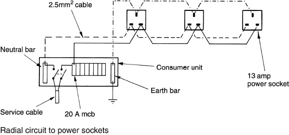
A radial circuit may be used as an alternative to a ring final circuit to supply any number of power sockets, provided the following limitations are effected:
Cable csa (mm2) |
Minimum overload protection (amps) |
Remarks |
|---|---|---|
2.5 |
20 |
Max. 20m2 floor area, 17m cable |
4.0 |
30 |
Max. 50m2 floor area, 21m cable |
With 2.5mm2 cable length limitation of 17m over 20m2 floor area for a radial supply to sockets, a ring main with a maximum cable length of 54 m over 100 m2 will usually prove to be more effective. Therefore radial circuits are more suited to the following:

Radial Extension to an Outbuilding
An electricity supply to an outside building may be overhead at a height not less than 3.5m. It may be supported in a conduit or from a catenary suspension wire. An underground supply is less obtrusive and should be at least 500mm below the surface. The cable should be armoured PVC sheathed or copper sheathed mineral insulated (MICC). Standard PVC insulated cable may be used, provided it is enclosed n a protective conduit. Fused isolators are required in the supply Building and the outside building, and a residual current device (RCD) ‘trip switch’ should also be installed after the fused switch control from the consumer unit. 2.5mm2 csa cable is adequate for limited installations containing no more than a power socket and lighting. In excess of this, a 4mm2 csa cable is preferred, particularly if the outbuilding is some distance to overcome the voltage drop.

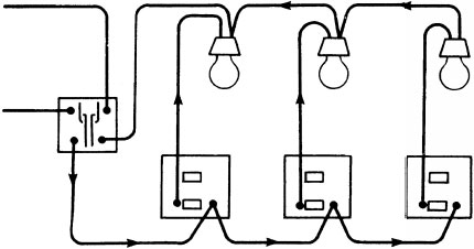
Lighting circuits can incorporate various switching arrangements. In a one-way switch circuit the single-pole switch must be connected to the line conductor. To ensure that both line and neutral conductors are isolated from the supply a double-pole switch may be used, although these are generally limited to installations in larger buildings where the number and type of light fittings demand a relatively high current flow.
Provided the voltage drop (4% max., see page 526) is not exceeded, two or more lamps may be controlled by a one-way single-pole switch. I n principle, the two-way switch is a single-pole change-over switch interconnected in pairs. Two switches provide control of one or more lamps from two positions, such as that found in stair/landing, bedroom and corridor situations. In large buildings, every access point should have its own lighting control switch. Any number of these may be incorporated into a two-way switch circuit. These additional controls are known as intermediate switches. See lower details below and page 514.
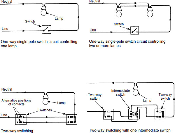
Note: Cpc to earth also required between switch and lamp fitments, but omitted here for clarity.
The purpose of a ‘master’ switch is to limit or vary the scope of control afforded by other switches in the same circuit. If a ‘master’ switch (possibly one with a detachable key option) is fixed near the main door of a house or flat, the householder is provided with a means of controlling all the lights from one position.
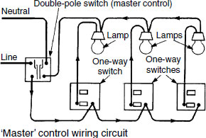
Note: Cpc omitted as indicated on preceding page.
A sub-circuit for lighting is generally limited to a total load of 10, 100 watt light fittings. It requires a 5 amp fuse or 6 amp mcb overload protection at the consumer unit. The importance of not exceeding these ratings can be seen from the simple relationship between current (amps), power (watts) and potential (voltage), i.e. Amps = Watts ÷ Volts. To avoid overloading the fuse or mcb, the limit of 10 lamps @ 100 watts becomes:
![]()
i.e. < 5 amps fuse protection.
In large buildings higher rated overload protection is often used due to the greater load.
Wiring for lighting is usually undertaken using the ‘looping-in’ system, although it is possible to use junction boxes instead of ceiling roses for connections to switches and light fittings.

Two-way switching is convenient for hall/landing lighting control and for bedroom door/bedside control. Intermediate switching has application to long corridors and multi-flight stairways.
Two-way switching
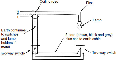
Intermediate switching

Sleeving – in addition to using green and yellow striped sleeving to all exposed earth conductors (see page 520), brown over-sleeving is used specifically in lighting circuits to part cover the blue, black and grey insulated conductors at switches and other terminals to identify where they provide continuity to the brown insulated line conductor.
Table and standard lamps, and up-lighters can plug into 13 amp plug power circuit sockets provided the plug is fitted with a low- amperage (3 amp) fuse. This may occupy power sockets that might be better used for appliances. Also, these sockets are considerably overrated for most supplementary light fittings. Therefore, a dedicated sub-circuit can be provided for light fittings from a socket spur as shown below:
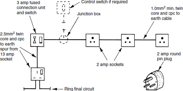
Features:
Light fitting flex attached to small round pin plugs (historically used for old-style 2 amp power circuits – now obsolete practice).
Unswitched 2 amp rated socket face plates purpose made for small round pin plugs fitted to single back boxes.
Switched and fused (3 amp) connection unit spurred off an existing 13 amp power socket with 2.5 mm2 csa cable.
1.0mm2 min. csa cable from fused connection unit to each 2 amp socket.
Sub-circuit max. power output of 690 watts, derived from 3 amp circuit protection x 230 volt supply.
Individual lamps controlled with their own fitment switch.
Accessible Switches and Sockets
The Building Regulations require reasonable provision for people, whether ambulant or confined to a wheelchair, to be able to use a building and its facilities. Facilities include wall-mounted switches and sockets located within easy reach, to be easily operated, visible and free of obstruction.
Dwellings – switches and sockets between 450 and 1200mm from finished floor level (ffl).

Non-domestic buildings – basic requirements for switches, outlets and controls:
Conventional and familiar.
Contrasting in colour to their surroundings.
Large push pad preferred or extra-wide rocker switches.
Pictogram to clarify use and purpose where multiple switches occur.
Separation or gap between individual switches where multiples exist.
Recommendations for location of wall-mounted switches and sockets in non-domestic buildings:
Sockets for TV, power and telephone: 400 to 1000mm above ffl and ≥350mm from corners. Power socket switches to indicate whether they are ‘ON’.
Switches to permanently wired appliances: 400 to 1200mm above ffl.
Controls requiring precise hand movement: 750 to 1200mm above ffl.
Push buttons, e.g. lift controls; ≤1200mm above ffl.
Pull cords for emergencies, coloured red and located close to a wall and to have 2, 50mm diameter bangles set 100mm and 800–900mm above ffl.
Controls that require close visual perception, e.g. thermostat, located 1200–1 400mm above ffl for convenience of people sitting or standing.
Light switches for general use of the push pad type and located at 900–1 100mm height. Alternatively, a pull cord with 50mm diameter bangle set at the same height. The pull cord should be distinguishable from any emergency pull.
Main and circuit isolators to clearly indicate that they are ‘ON’ or ‘OFF’.
Pattress or front plate to visually contrast with background.
Operation of switches and controls to be from one hand, unless both hands are required for safety reasons.
Note: Exceptions to the above may occur in unavoidable design situations such as open plan offices with fitted floor sockets.
Refs. Building Regulations, Approved Document M: Access to and use of buildings. Disability Discrimination Act.
BS 8300: Design of buildings and their approaches to meet the needs of disabled people – Code of Practice.
Electrical installations must be protected from current overload, otherwise appliances, cables and people using the equipment could be damaged. Protection devices may be considered in three categories:
Semi-enclosed (rewirable) fuses.
High breaking or rupturing capacity (HBC or HRC) cartridge fuses.
Miniature circuit-breakers (mcb).
None of these devices necessarily operate instantly. Their efficiency depends on the degree of overload. Rewirable fuses can have a fusing factor of up to twice their current rating and cartridge fuses up to about 1.6. Mcbs can carry some overload, but will be instantaneous (0.01 seconds) at very high currents.
Characteristics:
Semi-enclosed rewirable fuse:
Inexpensive.
Simple, i.e. no moving parts.
Prone to abuse (wrong wire could be used).
Age deterioration.
Unreliable with temperature variations.
Cannot be tested.
Cartridge fuse:
Compact.
Fairly inexpensive, but cost more than rewirable.
No moving parts.
Not repairable.
Could be abused.
Miniature circuit-breaker:
Relatively expensive.
Factory tested.
Instantaneous in high current flow.
Unlikely to be misused.

Refs. BS 88–1 and BS EN 60269: Low-voltage fuses. General requirements. BS 88–2 and 3 (BS HD 60269–2 and 3): Low-voltage fuses. Supplementary requirements........
Note: A standard prefixed by HD is a Harmonisation Document issued by CEN – see page 688.
BS EN 60898- 1 and 2: Electrical accessories. Circuit-breakers for over-current protection for household and similar installations.
Residual Current Devices (RCD) are required where a fault to earth may not produce sufficient current to operate an overload protection device (fuse or mcb), e.g. an overhead supply. If the impedance of the earth fault is too high to enable enough current to effect the overload protection, it is possible that current flowing to earth may generate enough heat to start a fire. Also, the metalwork affected may have a high potential relative to earth and if touched could produce a severe shock.
An RCD has the load current supplied through two equal and opposing coils, wound on a common transformer core. When the line and neutral currents are balanced (as they should be in a normal circuit), they produce equal and opposing fluxes in the transformer or magnetic coil. This means that no electromotive force is generated in the fault detector coil. If an earth fault occurs, more current flows in the line coil than the neutral and an alternating magnetic flux is produced to induce an electromotive force in the fault detector coil. The current generated in this coil activates a circuit-breaker.
While a complete system can be protected by a 100mA (milliamp) RCD, it is possible to fit specially equipped sockets with a 30mA RCD where these are intended for use with outside equipment. Plug-in RCDs are also available for this purpose. Where both are installed it is important that discrimination comes into effect. Lack of discrimination could effect both circuit-breakers simultaneously, isolating the whole system unnecessarily. Therefore the device with the larger operating current should be specified with a time delay mechanism.
The test resistor provides extra current to effect the circuit-breaker. This should be operated periodically to ensure that the mechanics of the circuit-breaker have not become ineffective due to dirt or age deterioration. A notice to this effect is attached to the RCD.
Ref. BS ENs 61008- 1 and 61009- 1: Residual current operated circuit-breakers.
An RCD is not appropriate for use with a TN-C system (i.e. combined neutral and earth used for the supply), as there will be no residual current when an earth fault occurs as there is no separate earth pathway.
They are used primarily in the following situations:
Where the electricity supply company do not provide an earth terminal, e.g. a TT overhead supply system.
I n bedrooms containing a shower cubicle.
For socket outlets supplying outdoor portable equipment.

A three-phase device operates on the same principle as a single-phase RCD, but with three equal and opposing coils.
PVC insulated and sheathed cable is now used for most electrical installations. The exceptions are for specialised applications using armoured or mineral insulated cable, and heat-resisting butyl rubber- insulated flex for connecting to heat-producing fittings such as immersion heater and cooker. Historically, lead outer sheathed rubber-insulated cable was used and may still be found in dated and unmodernised buildings.
PVC insulated cable has a temperature limitation of between 0° C and 70° C. Below zero it becomes brittle and can be damaged. At the higher temperature it softens which could encourage the conductor to migrate through the sheathing. Outside of these temperatures the cable must be protected or an appropriate rubber insulant specified.
Cables are manufactured with one, two or three insulated conductors, with or without a circuit protective conductor (cpc). The cpc is bare (i.e. uninsulated), and must be protected and easily identified with green and yellow sleeving where exposed at junction boxes, sockets, etc.
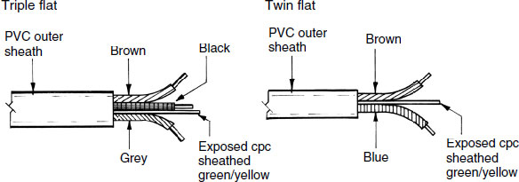
Note: Pre-2006 installations may have the line (phase) conductor colour coded red and the neutral black. Under a European harmonisation requirement, these are now identified brown and blue. For two-way lighting the old colours were red, yellow and blue, but are now identified as brown, black and grey.
Ref. BS EN 50525 series: Electric cables. Low-voltage energy cables of rated voltage up to and including 450/750V.
Conduit tubing is used for containment of electrical cables, continuity of support and protection against physical damage and heat. Conduit is available in galvanised or black-painted steel with screw-threaded connections and couplings. Lightweight plastic conduit has push fit connections. Standard outside diameters are 20, 25, 32, 40, 50 and 65mm in lengths of 3.750m. Shorter length requirements can be cut and threaded. Box section trunking is usually specified where a large capacity is required for multi-cable installations. With smaller diameter conduit, bends and offsets are formed with purpose-made portable tube benders. These are very similar to that used in plumbing for copper tube.

Ref. BS EN 61386–1: Conduit systems for cable management. General requirements.
Mineral insulated copper-covered (MICC) cable, otherwise known as mineral insulated metal sheathed (MIMS), has copper conductors insulated with highly compressed magnesium oxide powder inside a copper tube. It is resistant to most corrosive atmospheres and temperatures up to 150° C. Hence its suitability with fire alarms. Cutting and jointing the cable requires particular procedures that seal the insulant from penetration of dampness. The outer copper cover provides for circuit-protective continuity to earth.

Ref. BS EN 60702 (Parts 1 and 2): Mineral insulated cables and their terminations with a rated voltage not exceeding 750V [Cables – Part 1; Terminations – Part 2].
Armoured cable is used for underground main and sub-main supplies. It terminates at electricity substations or transformers and at the intake to high-voltage supplies for large buildings. Steel wire armour provides protection against physical damage.

It is rarely used for domestic and other relatively low-voltage applications, but is available if required for underground supplies to outbuildings such as a garage or workshop and for garden lighting.
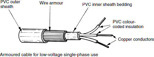
Refs. BS 6724 and BS 7846: Electric cables. Thermosetting insulated, armoured cables.
Testing Completed Installation
Electrical installations must be tested on completion to verify that the system will operate efficiently and safely. The tests are extensive, as defined in the Institution of Electrical Engineers Regulations. They can only be carried out by a competent person, i.e. a qualified electrician or electrical engineer. The following tests are an essential part of the proceedings:
Continuity.
I nsulation.
Polarity.
Testing is undertaken by visual inspection and the use of a multipurpose meter (multimeter) or an instrument specifically for recording resistance, i.e. an ohmmeter.
Continuity – there are several types of continuity test for ring final circuits. Each is to ensure integrity of the line, neutral and circuit protective (earth) conductors without bridging (shorting out) of connections. The following is one established test to be applied to each conductor:
Record the resistance between the ends of the ring circuit (A).
Record the resistance between closed ends of the circuit and a point midway in the circuit (B).
Check the resistance of the test lead (C).
Circuit integrity is indicated by: A ÷ 4 approx. = B – C.
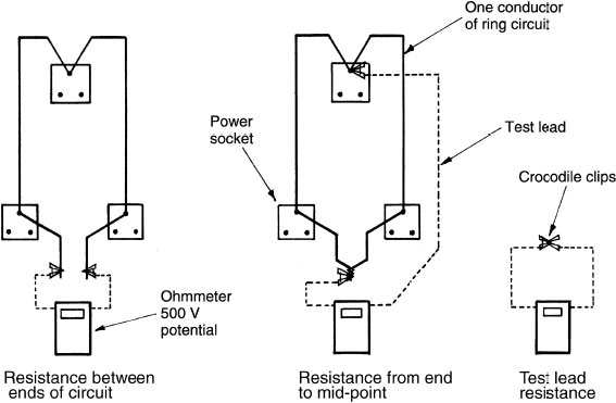
Note: Resistances A, B and C are also referred to as R1, R2 and R3.
Insulation – this test is to ensure that there is a high resistance between line and neutral conductors and these conductors and earth. A low resistance will result in current leakage and energy waste which could deteriorate the insulation and be a potential fire hazard. The test to earth requires all lamps and other equipment to be disconnected, all switches and circuit-breakers closed and fuses left in. Ohmmeter readings should be at least 1MΩ

Polarity – this is to ensure that all switches and circuit-breakers are connected in the phase or line conductor. An inadvertent connection of switchgear to a neutral conductor would lead to a very dangerous situation where apparent isolation of equipment would still leave it live! The test leads connect the line bar in the disconnected consumer unit to line terminals at switches. A very low resistance reading indicates the polarity is correct and operation of the switches will give a fluctuation on the ohmmeter.

Ref. BS EN 61010–1: Safety requirements for electrical equipment for measurement, control and laboratory use.
Standard applications |
Cable specification (mm2 c.s.a.) |
|---|---|
Lighting |
1 or 1·5 |
I mmersion heater |
1·5 or 2·5 |
Sockets (ring) |
2·5 |
Sockets (radial) |
2·5 or 4 (see page 510) |
Cooker |
6 or 10 |
Shower |
4, 6 or 10 (see page 392) |
Some variations occur as the specification will depend on the appliance or circuit loading – see calculation below. Where non-standard circuits or special installations are necessary, the cable specification must be calculated in the following stages:
Determine the current flowing.
Select an appropriate cable (see table below).
Check that the voltage drop is not greater than 4%.
Current ratings and voltage reduction for sheathed multi-core PVC insulated cables:

E.g. a 7.2kW shower with a clipped cable length of 10m:
Amps = Watts ÷ Volts = 7200 ÷ 230 = 31.3
From table, select 4mm2 csa (36 amps)
![]()
Maximum voltage drop = 230 × 4% = 9.2 volts.
Therefore, 4 mm2 csa cable is satisfactory.
Note: Correction factors may need to be applied, e.g. when cables are grouped, insulated or in an unusual temperature. The IEE regulations should be consulted to determine where corrections are necessary.
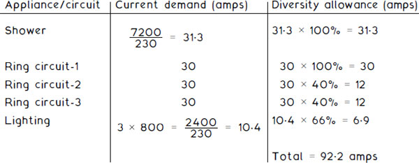
Diversity in electrical installations permits specification of cables and overload protection devices with regard to a sensible assessment of the maximum likely demand on a circuit. For instance, a ring circuit is protected by a 30 amp fuse or 32 amp mcb, although every socket is rated at 13 amps. Therefore if only three sockets were used at full rating, the fuse/mcb would be overloaded. In practice this does not occur, so some diversity can be incorporated into calculations.
Guidance for diversity in domestic installations:
Circuit |
Diversity factor |
|---|---|
Lighting |
66% of the total current demand. |
Power sockets |
100% of the largest circuit full load current + 40% of the remainder. |
Cooker |
10 amps + 30% full load + 5 amps if a socket outlet is provided. |
Immersion heater |
100%. |
Shower |
100% of highest rated + 100% of second highest + 25% of any remaining. |
Storage radiators |
100%. |
E.g. a house with 7.2kW shower, 3kW immersion heater, three ring circuits and three lighting circuits of 800W each:
Electrical Installation in a Factory
For a factory of modest size where the electrical load is not too high, a three-phase, four-wire, 400 volts supply will be sufficient. The distribution to three-phase motors is through exposed copper busbars in steel trunking running around the periphery of the building. Supply to individual motors is through steel conduit via push button switchgear. In addition to providing protection and support, the trunking and conduit can be used as earth continuity.

Switches must be within easy reach of machinery operators and contain a device to prevent restarting of the motor after a power failure stoppage.
Overhead busbars provide an easily accessible means of connecting supplies to machinery by bolting the cable to the busbars.
Lighting and other single-phase circuits are supplied through separate distribution fuse boards.
Refs. BS ENs 60439–1 and 2, BS ENs 61439–1 and 2: Low-voltage switchgear and controlgear assemblies.
Electricity Supply to Groups of Large Buildings
For large developments containing several buildings, either radial or ring distribution systems may be used.
Radial system – separate underground cables are laid from the substation to each building. The system uses more cable than the ring system, but only one fused switch is required below the distribution boards in each building.
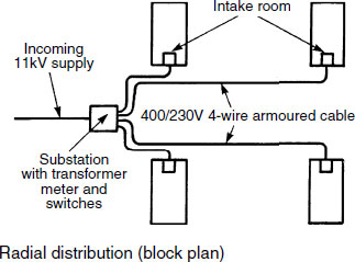
Ring circuit system – an underground cable is laid from the substation to loop into each building. To isolate the supply, two fused switches are required below the distribution boards in each building. Current flows in both directions from the intake, to provide a better balance than the radial system. If the cable on the ring is damaged at any point, it can be isolated for repair without loss of supply to any of the buildings.

Rising Main Electricity Distribution
The rising main supply system is used in high-rise offices and flats. Copper busbars run vertically inside trunking and are given support by insulated bars across the trunking chamber. The supply to each floor is connected to the rising main by means of tap-off units. To balance electrical distribution across the phases, connections at each floor should be spread between the phase bars. If a six-storey building has the same loading on each floor, two floors would be supplied from separate phases. Flats and apartments will require a meter at each tap-off unit.
To prevent the spread of fire and smoke, fire barriers are incorporated with the busbar chamber at each compartment floor level. The chamber must also be fire stopped to the full depth of the floor.
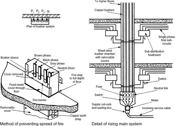
Ref. Building Regulations, Approved Document B3: Internal fire spread (structure).
It is uneconomical to shut down electricity-generating plant overnight, even though there is considerably less demand. To encourage the use of off-peak energy, the electricity supply companies offer it at an inexpensive tariff. A timer and white meter or Economy 7 (midnight to 0700) meter controls the supply to an energy storage facility. See also Economy 10, page 533.
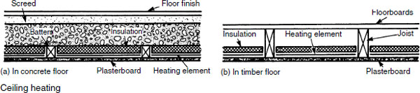
Underfloor – makes use of the thermal storage properties of a concrete floor. High-resisting insulated conductors are embedded in the floor screed at 100 to 200 mm spacing, depending on the desired output. This is about 10 to 20W/m of cable. To be fully effective the underside of the screed should be completely insulated and thermostatic regulators set in the floor and the room.
Block heaters – these are rated between 1 kW and 6 kW and incorporate concrete blocks to absorb the off-peak energy (see next page).

Electrically heated ceilings use standard tariff electricity supply. The heating element is flexible glasscloth with a conducting silicone elastomer.
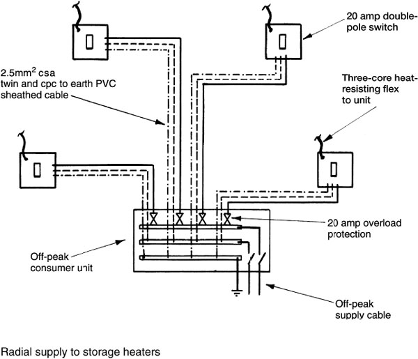
Night storage heaters – these have developed from very bulky cabinets containing concrete blocks which effectively absorb the overnight electrical energy and dissipate it gradually during the next day. Improvements in storage block material have considerably reduced the size of these units to compare favourably with conventional hot water radiators. They contain a number of controls, including a manually set input thermostat on each heater, an internal thermostat to prevent overheating and a time-programmed fan. Manufacturers provide design tables to establish unit size. As a rough guide, a modern house will require about 200W output per square metre of floor area. Storage heaters are individually wired on radial circuits from the off-peak time-controlled consumer unit.
Economy 10 – a variation on Economy 7 (see pages 111 and 531) that is sometimes referred to as ‘Warmwise’. It is suitable where discounted electricity is used as the energy source for both space heating and hot water supply. Often installed as an upgrade to an Economy 7 system in homes where the hot water and storage heaters are losing heat by the evening, typical of households where occupancy has increased.
All electric heating system emitters have improved from their origins as bulky storage radiators that contain heavy concrete blocks as the off-peak electrical energy-absorbing material. Contemporary electric combination radiators are much slimmer, with overall dimensions that compare favourably with hot water convector radiators. Also, they do not require separate provision for a centralised hot water boiler, extensive pipework, cisterns and associated controls, effecting a considerable saving in space and installation time. Electric emitters can plug into a standard socket, but for maximum economy a dedicated spur is provided from an Economy 10 meter as indicated on the previous page. The ten off-peak reduced tariff hours can vary depending on supplier, but are usually either:
Midnight to 7 am and 1 pm to 4 pm, or
Midnight to 5 am, 1 pm to 4 pm and 8 pm to 10 pm.
Radiator output – individual units ranging from 500 to 2500 Watts.
Function – comprise heat-retaining ceramic tablets or cells that contain an embedded heating element.
Control – each emitter has a built-in thermostat for modulating heat output. This can be set manually for independent control or be controlled centrally from a remote room thermostat that also regulates all other emitters to effectively centrally heat a whole building.
Application – most suited for apartments and dwellings of limited size. Also as a retro-fit in existing dwellings, as cable installation is considerably less disruptive to the structure than a hot water system.
Electrically heated warm air systems are a development of the storage heater concept – see previous three pages. A central unit rated from 6kW to 12kW absorbs electrical energy off-peak and during the day delivers this by fan to various rooms through a system of insulated ducting. A room thermostat controls the fan to maintain the air temperature at the desired level. Air volume to individual rooms is controlled through an outlet register or diffuser.
Stub duct system – the unit is located centrally and warm air is conveyed to rooms through short ducts with attached outlets.
Radial duct system – warm air from the unit is supplied through several radial ducts designated to specific rooms. Outlet registers are located at the periphery of rooms to create a balanced heat distribution.

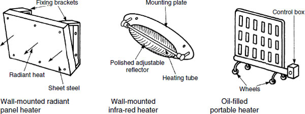
There are numerous types of independent heat emitters for use with 13 amp power sockets or fused spur sockets.
Panel heater – the heat output is mainly radiant from a surface operating temperature of between 204°C and 240°C. For safety reasons it is mounted at high level and may be guarded with a mesh screen.
Infra-red heater – contains an iconel-sheathed element or nickel chrome spiral element in a glass tube, backed by a curved reflector. May be used at high level in a bathroom and controlled with a string pull.
Oil-filled heater – similar in appearance to steel hot water radiators, they use oil as a heat-absorbing medium from one or two electrical elements. Heat is emitted by radiant and convected energy. An integral thermostat allows for manual adjustment of output.
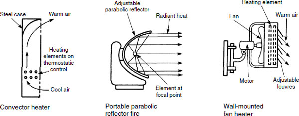
Convector heater – usually has two electrical elements with independent control to vary the output. May be used where a constant level of background warmth is required.
Parabolic reflector fire – has the heating element in the focal point to create efficient radiant heat output.
Wall-mounted fan heaters – usually provided with a two-speed fan to deliver air through a bank of electrical elements at varying velocities. Direction is determined by adjustable louvres.
Controls For Electric Night Storage Space Heaters
Controls vary from simple switches and sensors integrated with appliances, to overall system management programmed through time switches and optimisers:
Manual charge control – set by the user to regulate energy input and output. The effect can be variable and unreliable as it does not take into account inconsistencies such as daily variations in temperature.
Automatic charge control – sensors within the heater and room are pre-set to regulate the electrical input charge. When room temperature is high, the sensor in the heater reduces the energy input. Conversely, the energy input is increased when the room temperature is low.
Heat output control – this is a damper within the heater casing. It can be adjusted manually to regulate heat emission and prevent a room from overheating. A variable speed fan can be used to similar effect or to vary the amount of heat emission and its distribution.
Time switch/programmer and room thermostat – the simplest type of programmed automatic control applied individually to each heater or as a means of system or group control. Where applied to a system of several emitters, individual heaters should still have some means of manual or preferably automatic regulation. This type of programmed timing is also appropriate for use with direct acting thermostatically switched panel-type heaters.
‘CELECT-type’ controls – this is a type of optimiser control which responds to pre-programmed times and settings, in addition to unknown external influences such as variations in the weather. Zones or rooms have sensors which relate room information to the controller or system manager, which in turn automatically adjusts individual storage heater charge periods and amount of energy input to suit the room criteria. This type of control can also be used for switching of panel heaters.
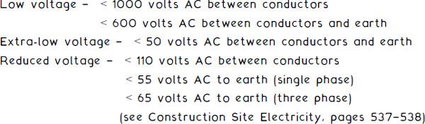
A temporary supply of electricity for construction work may be obtained from portable generators. This may be adequate for small sites but most developments will require a mains supply, possibly up to 400 volts in three phases for operating hoists and cranes. Application must be made in good time to the local electricity authority to ascertain the type of supply and the total load. The incoming metered supply provided by the electricity company will be housed in a temporary structure constructed to the authority’s approval. Thereafter, site distribution and installation of reduced voltage transformers is undertaken by the developer’s electrical contractor subject to the supply company’s inspection and testing.
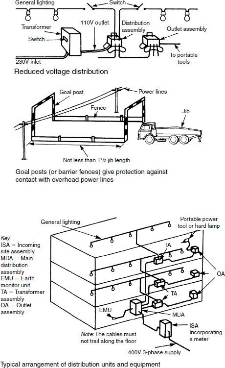
Incoming site assembly (ISA) – provided by the local electricity supply company. It contains their switchgear, overload protection, transformers and meters for a 400 volt, three-phase supply at 300, 200 and 100 amps.
Main distribution assembly (MDA) – contains three-phase and singlephase distribution boards, overload protection and lockable switchgear. May be combined with the ISA to become an ISDA. Transformer assembly (TA) – supplied from the MDA to transform voltage down to 110V, 50V and possibly 25V for use in very damp situations.
Earth monitor unit (EMU) – used where mobile plant requires flexible cables at mains voltage. A very low-voltage current is conducted between plant and EMU and earth conductor, so that if this is interrupted by a fault a monitoring unit disconnects the supply.
Socket outlet assembly (SOA) – a 110 volt supply source at 32 amps with switchgear and miniature circuit-breakers for up to eight 16 amp double-pole sockets to portable tools.
Cable colour codes and corresponding operating voltage:
Colour |
Voltage |
|---|---|
Violet |
25 |
White |
50 |
Yellow |
110 |
Blue |
230 |
Red |
400 |
Black |
500/650 |
Refs. BS A363: Specification for distribution assemblies for reduced low-voltage electricity supplies for construction and building sites.
BS 737S: Distribution of electricity on construction and demolition sites. Code of practice.
BS EN 60A39-A: Low-voltage switchgear and controlgear assemblies. Particular requirements for assemblies for construction sites.
Light is a form of electromagnetic radiation. It is similar in nature and behaviour to radio waves at one end of the frequency spectrum and X-rays at the other. Light is reflected from a polished (specular) surface at the same angle that strikes it. A matt surface reflects in a number of directions and a semi-matt surface responds somewhere between a polished and a matt surface.
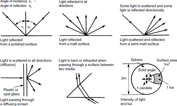
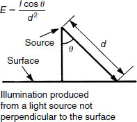
Illumination produced from a light source perpendicular to the surface:
![]()
E = illumination on surface (lux)
I = Illumination intensity from source (candela or cd)
d = distance from light source to surface (metre or m).
The inverse square law – intensity of illumination from a point source of light decreases inversely with the square of the distance from the source. The illustration below represents this principle.

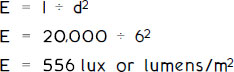
E.g. 1 – A spotlight of luminous intensity 20,000 candelas directed perpendicularly onto a flat surface at 6m distance. Using the formula shown on the previous page, applying the inverse square law principle:
Cosine illumination law – this provides a correction to the inverse square law formula to allow for the subject area being at an angle from the light source. This is appropriate for most lighting applications as large parts of a surface will not receive light directly in the perpendicular. The modified formula and concept is shown on the previous page.
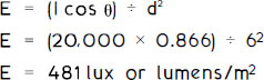
E.g. 2 – The light from the same spotlight in example 1 is directed at 30° (angle 0) onto a subject 6m away. The illumination will be:
Definitions and units of measurement:
Luminous intensity – candela (cd), a measurement of the magnitude of luminance or light reflected from a surface, i.e. cd/m2.
Luminous flux – lumen (lm), a measurement of the visible light energy emitted.
Illuminance – lumens per square metre (lm/m2) or lux (lx), a measure of the light falling on a surface.
Efficacy – efficiency of lamps in lumens per watt (lm/W). Luminous efficacy = Luminous flux output ÷ Electrical power input.
Glare index – a numerical comparison ranging from about 10 for shaded light to about 30 for an exposed lamp. Calculated by considering the light source size, location, luminances and effect of its surroundings.
Examples of illumination levels and limiting glare indices for different activities:
Activity/location |
Illuminance (lux) |
Limiting glare index |
|---|---|---|
Assembly work: (general) |
250 |
25 |
(fine) |
1000 |
22 |
Computer room |
300 |
16 |
House |
50 to 300* |
n/a |
Laboratory |
500 |
16 |
Lecture/classroom |
300 |
16 |
Offices: (general) |
500 |
19 |
(drawing) |
750 |
16 |
Public house bar |
150 |
22 |
Shops/supermarkets |
500 |
22 |
Restaurant |
100 |
22 |
* Varies from 50 in bedrooms to 300 in kitchen and study.
The Building Regulations, Approved Document L2 requires that non-domestic buildings have reasonably efficient lighting systems and make use of daylight where appropriate.
Filament lamps – the tungsten iodine lamp is used for floodlighting. Evaporation from the filament is controlled by the presence of i odine vapour. The gas-filled, general-purpose filament lamp has a fine tungsten wire sealed within a glass bulb. The wire is heated to incandescence (white heat) by the passage of an electric current.
Discharge lamps – these do not have a filament, but produce light by excitation of a gas. When voltage is applied to the two electrodes, ionisation occurs until a critical value is reached when current flows between them. As the temperature rises, the mercury vaporises and electrical discharge between the main electrodes causes light to be emitted.
Fluorescent tube – this is a low-pressure variation of the mercury discharge lamp. Energised mercury atoms emit ultraviolet radiation and a blue/green light. The tube is coated internally with a fluorescent powder which absorbs the ultraviolet light and re-radiates it as visible light.

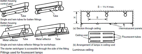
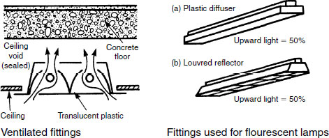
Fluorescent strip lamps have many applications. The fittings and reflectors shown are appropriate for use in industrial locations, with a variation which creates an illuminated ceiling more suited to shops and offices. A false ceiling of thermaluscent panels provides well-diffused illumination without glare and contributes to the insulation of the ceiling. Other services should not be installed in the void as they will cast shadows onto the ceiling. Tubes are mounted on batten fittings and the inside of the void should be painted white to maximise effect.
High-pressure sodium discharge lamps produce a consistent golden white light in which it is possible to distinguish colours. They are suitable for floodlighting, commercial and industrial lighting and illumination of highways. The low-pressure variant produces light that is virtually monochromatic. The colour rendering is poor when compared to the high-pressure lamp. Sodium vapour pressure for high- and low-pressure lamps is 0.5Pa and 33kPa, and typical efficacy is 125 and 180l m/W respectively.

Fittings for lighting may be considered in three categories:
General utility – designed to be effective, functional and economic.
Special – usually provided with optical arrangements such as lenses or reflectors to give directional lighting.
Decorative – designed to be aesthetically pleasing or to provide a feature, rather than to be functional.
From an optical perspective, the fitting should obscure the lamp from the discomfort of direct vision to reduce the impact of glare.

Ventilated fittings allow the heat produced by the lamps to be recirculated through a ceiling void to supplement a warm air ventilation system. The cooling effect on the lamp will also improve its efficiency.
Luminaire – a word to describe the complete lighting unit including the lamp. When selecting a lamp type, it is important to select a luminaire to complement the lamp both functionally and aesthetically. A luminaire has several functions: it defines the lamp position, protects the lamp and may contain the lamp control mechanism. In the interests of safety it must be well insulated, in some circumstances resistant to moisture, have adequate appearance for purpose and be durable.
Polar curve – shows the directional qualities of light from a lamp and luminaire by graphical representation, as shown in outline on the previous page. A detailed plot can be produced on polar coordinated paper from data obtained by photometer readings at various angles from the lamp. The coordinates are joined to produce a curve.
Typical representation:

Compact fluorescent lamps are a smaller variation and development of the standard fluorescent tube fitting. They are manufactured with conventional bayonet or screw fittings. Unit cost is higher than tungsten filament bulbs but will last for over 8000 hours, consuming only about 25% of the energy of a conventional bulb. Tungsten filament bulbs have a life expectancy of about 1000 hours.
The comfort type produces gentle diffused light and is suitable where continuous illumination is required. The prismatic types are more robust and are suitable for application to workshops and commercial premises. Electronic types are the most efficient, consuming only 20% of the energy that would be used in a tungsten filament bulb. Compact fluorescent lamps are not appropriate for use with dimmer switches.

The Buildings Regulations, Approved Document L, lists compact fluorescent lamps as an acceptable means for lighting buildings.
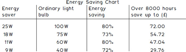
Domestic energy costed at 12 p/kWh
Only a small proportion of the energy in a light fitting is converted into light. All the energy dissipated is a measure of heat.
Tungsten filament lamp – heat contribution is the power rating quoted on the bulb.
Fluorescent tube – heat contribution is the power rating plus about 25% attributed to heat energy from the control gear.
High levels of artificial lighting can make a significant contribution to the heating load of a building. This may be useful in winter, but at other times it can cause an overheating problem. A possible solution is combination duct extract/luminaires as shown on pages 278, 279, 281 and 544. Some 40–50% of the lighting heat energy can be directed through a controlled extract or preferably recycled through a heat exchanger. Also, the cooling effect on the light fitting should contribute to its life expectancy. Polyphosphor tubes should not be used in extract luminaries, as the illuminance effect will be reduced.
The following table indicates the approximate heat dissipation, relative to the type of light fitting and level of illuminance:

Proportionate distribution of energy from lamps and tubes:

Interior lighting – the energy consumed by lighting in dwellings depends on the overall performance and efficiency of luminaires, lamps and control gear. The Building Regulations require that fixed lighting in a reasonable number of locations where lighting has most use (see table) be fitted with lamps having a luminous efficacy in excess of 40 lumens per circuit-watt. The term circuit-watt is used instead of watt, as this includes the power used by the lamp plus the installation and control gear.
Guidance on number of locations where efficient lighting should be provided:
Rooms created in a dwelling |
Minimum number of locations |
|---|---|
1–3 |
1 |
4–6 |
2 |
7–9 |
3 |
10–12 |
4 |
Hall, stairs and landing are regarded as one room.
An integral (attached to the building) conservatory is considered a room.
Garages, loft and outbuildings are not included.
Exterior lighting – reasonable provisions are required for economical use. This could include any of the following or a combination of:
efficient lamps
automatic timed switching control
photo-electric switching control.
Note: Lamps that satisfy the criteria of efficiency include fluorescent tubes and compact fluorescent lamps. Special socket fittings can be made to prevent interchange with unsuitable standard tungsten lamps.
Refs. Building Regulations, Approved Document L1: Conservation of fuel and power in dwellings.
Low-energy domestic lighting – ref. GIL 20, BRESCU publications.
Lighting Controls – Non-domestic Buildings
Lighting efficiency is expressed as the initial (100-hour) efficacy averaged over the whole building –
Offices, industrial and storage buildings, not less than 40 luminaire-lumens per circuit-watt.
Other buildings, not less than 50 lamp-lumens per circuit-watt.
Display lighting, not less than 15 lamp-lumens per circuit-watt.
A formula and tables for establishing conformity with these criteria are provided in the Building Regulations, Approved Document.
Lighting control objectives:
to maximise daylight
to avoid unnecessary use of artificial lighting when spaces are unoccupied.
Control facilities:
Local, easily accessible manual switches or remote devices including infra-red transmitters, sonic, ultrasonic and telecommunication controls.
Plan distance from switch to luminaire, maximum 8 metres or three times fitting height above floor (take greater).
Time switches as appropriate to occupancy.
Photoelectric light metering switches.
Automatic infra-red sensor switches which detect the absence or presence of occupants.
Controls specific to display lighting include dedicated circuits that can be manually switched off when exhibits or merchandise presentations are not required. Timed switching that automatically switches off when premises are closed.
Refs. Building Regulations, Approved Document L2: Conservation of fuel and power in buildings other than dwellings.
BRE Information Paper 2/99, Photoelectric control of lighting: design, set-up and installation issues.
Extra-low-voltage lighting has application to display lighting for shops and exhibitions. It is also used as feature lighting in domestic premises where set in the ceiling in kitchens and bathrooms. These situations benefit from the low heat emission, good colour rendering and very low running costs of this form of lighting. System potential is only 12 volts AC, through a transformed 230 volt mains supply. Highperformance 50 watt tungsten halogen dichroic lamps are compact and fit flush with the mounting surface.
Electricity is supplied from the transformer through a fused splitter to provide a fairly uniform short length of cable to each lamp. Similarity in cable lengths is important to maintain equivalent voltage drop and a short length of cable will minimise voltage drop. Lamps are very sensitive to change in voltage, therefore the correct selection of transformer is essential. A voltage drop of 6% (approx. 0.7 volts) will reduce the illuminating effect by about 30%. Cable sizing is also critical with regard to voltage drop. The low voltage creates a high current, i.e. just one 50 watt bulb at 12 volts = 4.17 amps (see page 526 for cable sizing).
Schematic ELV lighting:
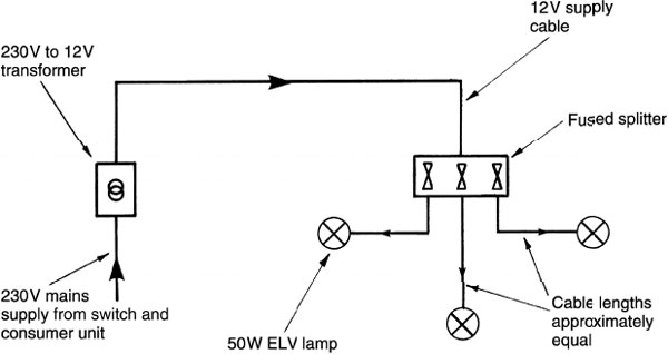
Note: A variation is the use of individual low-voltage lamps which contain their own transformer. However, these are relatively expensive items and are attached to special fittings.
Emission from a tungsten-halogen bulb is up to three times that of a filament bulb, e.g. a 50 watt halogen bulb has comparable light output to one 150 watt filament bulb.
A guide or ‘rule of thumb’ that can be used to estimate the number of halogen bulbs required is: one 20W lamp per square metre of floor or one 50W lamp per one-and-a-half square metres of floor.
Alternative applications to that shown on the previous page:

Note: neither the 12V light fittings nor the transformer are earthed.
Definitions:
Lumen Method of Lighting Design
The lumen method of lighting design is used to determine a lighting layout that will provide a design-maintained illuminance. It is valid if the luminaires are mounted above the working plane in a regular pattern. The method uses the formula: N = (E × A) ÷ ( F × U × M).
N = number of lamps
E = average illuminance on the working plane (lux)
A = area of the working plane (m2)
F = flux from one lamp (lumens)
U = utilisation factor
M = maintenance factor.
The utilisation factor (U) is the ratio of the lumens received on the working plane to the total flux output of lamps in the scheme. The maintenance factor (M) is a ratio which takes into account the light lost due to an average expectation of dirtiness of light fittings and surfaces.
Spacing-to-height ratio (SHR) is the centre-to-centre (S) distance between adjacent luminaires to their mounting height (H) above the working plane. Manufacturers – catalogues can be consulted to determine maximum SHRs, e.g. a luminaire with trough reflector is about 165 and an enclosed diffuser about 1·4.

Permanent Supplementary Lighting of Interiors
Illumination of building interiors is a very important factor for designers. This will relate to user convenience and visual impact of the building. Overall considerations fall into three categories:
A – daylighting alone, in which the window area occupies about 80% of the facades
B – permanent supplementary artificial lighting of interiors, in which the window area is about 20% of the facades
C – permanent artificial lighting of interiors in which there are no windows.
Occupants of buildings usually prefer a view to the outside. Therefore the choice of lighting for most buildings is from type A or B. With type B the building may be wider, because artificial lighting is used to supplement daylighting. Although the volume is the same as type A the building perimeter is less, thus saving in wall construction. Type B building also has lower heat gains and energy losses through the glazing, less noise from outside and less maintenance of windows.

Ref. BS EN 12464–1: Light and lighting.
Lighting of workplaces. Indoor workplaces.
The daylight received inside a building can be expressed as ‘the ratio of the illumination at the working point indoors, to the total light available simultaneously outdoors’. This can also be expressed as a percentage and it is known as the ‘daylight factor’.
The daylight factor includes light from:
Sky component – light received directly from the sky; excluding direct sunlight.
External reflected component – light received from exterior reflecting surfaces.
Internal reflected component – light received from internal reflecting surfaces.
If equal daylight factor contours are drawn for a room, they will indicate how daylighting falls as distance increases from a window.

Refs. BRE Digests 309 and 310: Estimating daylight in buildings.
BS 8206–2: Lighting for buildings. Code of practice for daylighting.
The effect of daylight in a room can be studied by using scaled models. Providing that textures and colours of a room surface are the same, an approximate result may be obtained.
An estimate of the effect of daylight in a room may also be made from daylight factor protractors and associated tables of data. These were developed by the Building Research Establishment for use with scaled drawings to determine the sky component from a sky of uniform luminance.
There are pairs of protractors to suit different window types. Protractor No. 1 is placed on the cross-section as shown. Readings are taken where the sight lines intersect the protractor scale.
In the diagram, the sky component = 8·5 − 4 = 4·5% and an altitude angle of 302° The sky component of 4·5% must be corrected by using protractor No. 2. This is placed on the plan as shown. Readings from protractor No. 2 are 0·25 and 0·1, giving a total correction factor of 0·35. Therefore 4·5 × 0·35 = 1·6%.
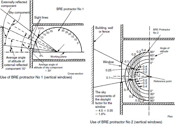
Note: Daylight protractors number 1 to 10. They are available with a guide from the Building Research Establishment, ref. Publication code AP 6B.
The external reflected component of the daylight factor for a uniform sky may be taken as approximately 0.1 × the equivalent sky component. Using the diagrams shown in Daylighting – 2, the value may be found as follows:
Readings from protractor No. 1 are 4% and 0·5%.
Equivalent sky component = 4% – 0·5% = 3·5%.
Average angle of altitude = 15°.
Readings on protractor No. 2 are 0·27 and 0·09 (for 15°).
Correction factor = 0·27 + 0·09 = 0·36.
Equivalent uniform sky component = 3·5% × 0·36 = 1·26%.
Externally reflected component = 0·1 × 1·26% = 0·126%.
To establish the daylight factor, the internal reflected component is calculated and added to both the sky and externally reflected components – see example.
Example: Find the minimum internally reflected component of the daylight factor for a room measuring 10m × 8m × 2·5m high, having a window in one wall with an area of 20m2. The floor has an average reflection factor of 20% and the walls and ceiling average reflection factors of 60% and 70% respectively.
Window area as a percentage of floor area ![]()
Referring to Table 2 (p. 557), the minimum internally reflected component = 1·3%.
Allowing a maintenance factor of 0.9 for dirt on the windows the value will be modified to 1·3 × 0·9 = 1·17%.
For the example given in daylighting 2 and 3 the daylight factor will be the addition of the three components = 1·6 + 0·126 + 1·17 = 2·9%.
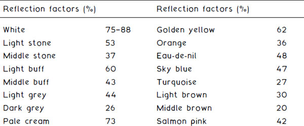
Table 2 Minimum internally reflected component of the daylight factor (%)
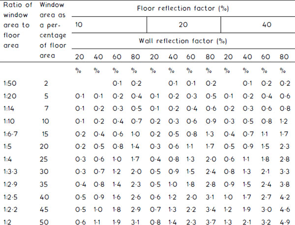
Note: The ceiling reflection factor is assumed to be 70%.
There are other methods for determining daylight factor. Some are simple rules of thumb and others more detailed formulae. An example of each is shown below.
Rule of thumb − D = 01 × P
where:
D = daylight factor
P = percentage of glazing relative to floor area.
E.g. a room 80m2 floor area with 15m2 of glazing.
![]()
Formula –
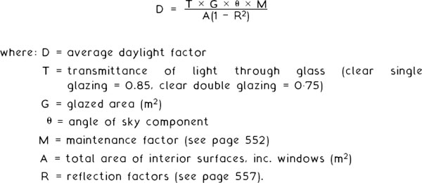
E.g. using the data from the example on page 556 and assuming a 50% reflection factor, double glazing and a sky component angle of 35°:
![]()
All calculations and estimates of daylight factor and glazing area must conform with the energy-saving requirements defined in the Building Regulations, Approved Document L – Conservation of Fuel and Power.
Previously this has included a maximum allowance for glazed areas relative to floor and external wall areas, but with the availability of quality double glazed units these limitations are now relaxed. See also page 187 and associated references.
Telecommunications Installation
Cabling systems that were originally used solely for telephone communications now have many other applications. These include fire alarms, security/intruder alarms, computer networking, teleprinters, facsimile machines, etc. The voltage and current are very low and have no direct connection to the mains electricity in a building. Therefore, telecommunications and mains cabling should be distinctly separated in independent conduits and trunking for reasons of safety and to prevent interference.
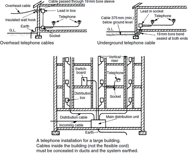
External telecommunications cables may supply a building from overhead or underground, the latter being standard for new building work. The intake is below surface level at a point agreed with the cable supplier. In large buildings the incoming cable supplies a main distribution unit which has connections for the various parts of the building. Cables supply both switchboards and individual telephones from vertical risers. There may be limitations on the number of cables supplied from risers, and early consultation with the cable supplier is essential to determine this and any other restrictions.
Notes