
Micro-Switch and Magnetic Reed
Radio Sensor, Pressure Mat and Taut Wiring
Acoustic, Vibration and Inertia Detectors
The first line of defence against intrusion includes physical measures that resist unwanted entry to the grounds and structure of a building. The second line of defence is an alarm system.
Some basic physical measures:
Spring or night latch – the typical front door latch that is in place when the door is closed. Very vulnerable due to a simple two-lever spring mechanism that can be moved by other means than a key. Opened from the inside without a key, therefore no problem for an intruder seeking an easy escape.
Deadlock – cannot function by just closing the door. Requires a key to lock it on leaving and when locked cannot be opened from the inside without a key. Espagnolette variation provides at least two more deadlocking positions throughout the height of the door or window frame, thus making it more difficult to force and smash the lock retainers/staples. Usually produced with a five-lever mechanism that is difficult to pick. No matter how sophisticated the ironmongery/brassware, weak and slender doors or window frames are always vulnerable to force.
Telephone – with overhead supplies these can easily be cut by would-be intruders. Most supplies are now under the ground in service ducts and therefore protected from abuse.
Glazing – double panes are primarily to improve thermal and sound insulation. They also provide an intruder with more of a problem and a hazard than single panes. Double glazed sealed units are difficult to break due to the air cushion between the panes.
Window casement fasteners and stays – can be fitted with locking devices, but these can have a negative effect if they cannot be opened for an emergency escape. Sufficient provision must be made for access through these escape routes in an emergency and they should not be permanently sealed. See Building Regulations Approved Documents B1 and B2, Section 2: Means of escape.
Simple means of protection – intruders often target buildings at night, under the cover of darkness. They dislike being illuminated at work; therefore a sufficient deterrent may be achieved by leaving external lights on a timed control. A more selective variation uses an infrared radiation movement detector (see pages 645–646) activated during hours of darkness. Another selective variation that could be used 24 hours a day incorporates a sound sensor or listening device that activates a light or radio transmitter in response to noise.
No amount of physical barriers, whether they be tall hedging, brick walls, fencing, door locks, etc., will prevent the most determined of intruders. The second line of defence, the intruder alarm, is regarded as the most effective deterrent, often just by its presence in the form of an alarm box mounted high on the face and rear of a building. These systems can be stand-alone (i.e. just used to raise a highly audible sound at the property), or they may be monitored systems, sometimes known as signalling systems. Monitored systems incorporate remote supervision through the telecommunications cables linked into the alarm circuit to a security company and possibly the local police.
Alarm installations – hard-wired (cable) systems to BS EN 50131 are the most reliable and conform to the ACPO alarm policy. An alternative is a wire-free or radio frequency installation that has appeal to the DIY market. These plug-in kits are relatively simple to install and have little disruptive effect to the finishes and structure. Wire-free systems satisfying BS EN 50131 are accepted by the ACPO alarm policy . Lesser classifications may well respond satisfactorily to an intruder, but may also be triggered by radio frequencies transmitted by other equipment.
Refs. BS EN 50131-1: Alarm systems. Intrusion and hold-up systems. System requirements.
ACPO: Association of Chief Police Officers.
Police response to alarm activations depends on the type of alarm system installed. There are a high number of false alarms as a result of user misuse and/or equipment error. Therefore, the Association of Chief Police Officers have adopted a Unified Intruder Alarm Policy for responding to alarm signals. This policy designates alarm systems into two separate categories or types, each having a defined response:
Type A – remote signalling or monitored alarm systems. Maintained and used in accordance with the recommendations of BS EN 50131. These systems are registered with an alarm-monitoring agent and with the police. When activated the monitoring agent will liaise with the police after telephoning the building owner or a nominated key holder (usually a neighbour for domestic systems) to establish whether the alarm activation is genuine or accidental. A password is determined and if the monitoring agent considers that the response is inappropriate or non-existant, they will confirm this with the police. Police response will depend on priority of other commitments at the time and a consideration of the number of recent false activations at the premises.
Type B – stand-alone or audible-only unmonitored systems. These will only attract a police response if there is supplementary information in the form of an witness report that an offence is in progress. This category can also include some systems known in the industry as hybrids. These are monitored to a certain extent by including an automatic dialling facility to a security company.
Independent alarm inspection and certification authorities –
National Approval Council for Security Systems (NACSS).
Security Systems and Alarm Inspection Board (SSAIB).
Refs. BS 4737-4.3: Intruder alarm systems in buildings. Codes of practice. Code of practice for exterior alarm systems.
PD 6662: Scheme for the application of European Standards for intruder and hold-up alarm systems.
Some intruder alarm detection devices are considered between pages 639–646.
Intruder alarms have developed from a very limited specialist element of electrical installation work in high-security buildings to the much wider market of schools, shops, offices, housing, etc. This is largely a result of the economics of sophisticated technology surpassing the efficiency of manual security. It is also a response to the increase in burglaries at a domestic level. Alarm components are an alarm bell or siren activated through a programmer from switches or activators. Power is from mains electricity with a battery back-up. Extended links can also be established with the local police, a security company and the facility manager’s central control by telecommunication connection.
Selection of switches to effect the alarm will depend on the building purpose, the extent of security specified, the building location and the construction features. Popular applications include:
Micro-switch
Magnetic reed
Radio sensor
Pressure mat
Taut wiring
Window strip
Acoustic detector
Vibration, impact or inertia detector.
The alternative, which may also be integrated with switch systems, is space protection. This category of detectors includes:
Ultrasonic
Microwave
Active infra-red
Passive infra-red
Circuit wiring may be ‘open’ or ‘closed’ as shown in principle for fire alarms – see pages 619 and 620. The disadvantage of an open circuit is that if an intruder knows the whereabouts of cables, the detector circuit can be cut to render the system inoperative. Cutting a closed circuit will effect the alarm.
The following references provide detailed specifications:
BS EN 50131-1: Alarm systems. Intrusion and hold-up systems. System requirements.
DD CLC/TS 50131-7: Alarm systems. Intrusion and hold-up systems.
Application guidelines.
Micro-switch and Magnetic Reed
Micro-switch – a small component which is easily located in door or window openings. It is the same concept and application as the automatic light switch used in a vehicle door recess, but it activates an alarm siren. A spring-loaded plunger functions in a similar manner to a bell push button in making or breaking an electrical alarm detector circuit. The disadvantage is the constant movement and associated wear, exposure to damage and possible interference.
Magnetic reed – can be used in the same situations as a micro-switch but it has the advantage of no moving parts. It is also less exposed to damage or tampering. There are, however, two parts to install. One is a plastic case with two overlapping metal strips of dissimilar polarity, fitted into a small recess in the door or window frame. The other is a magnetic plate attached opposingly to the door or window. When the magnet is close to the overlapping strips, a magnetic field creates electrical continuity between them to maintain circuit integrity. Opening the door or window demagnetises the metal strips, breaking the continuity of the closed detector circuit.

Radio Sensor, Pressure Mat and Taut Wiring
Radio sensor – these are surface mounted to windows and doors. They transmit a radio signal from an integral battery power source. This signal is picked up by a central control unit or receiver, which activates the alarm circuit. As these sensors are ‘free wired’ they can be moved, which is ideal for temporary premises or in buildings undergoing changes. A pocket or portable radio panic button transmitter is an option. The range without an aerial is about 60m; therefore they can be used in outbuildings to a hard-wired system from a main building.
Pressure mat – these are a ‘sandwich’ with metal foil outer layers as part of a detector circuit. The inner core is a soft perforated foam. Pressure on the outer upper layer connects to the lower layer through the perforations in the core to complete the circuit and activate the alarm. Location is near entrances and under windows, normally below a carpet where a small area of underlay can be removed. Sensitivity varies for different applications, such as premises where household pets occupy the building.
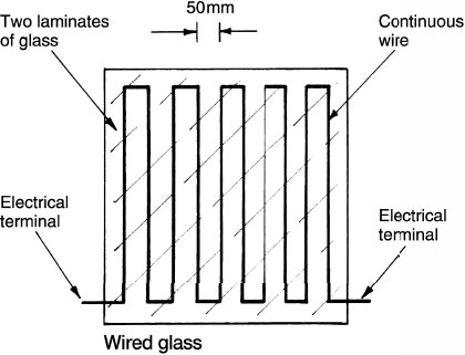
Taut wiring – also available as a window strip. A continuous plastic-coated copper wire is embedded in floors, walls or ceilings, or possibly applied around safes and other secure compartments. As a window strip, silvered wire can be embedded between two bonded laminates of glass. Alternatively, a continuous self-adhesive lead or aluminium tape can be applied directly to the surface. In principle, it is similar to a car rear-heated window. When the wire or tape is broken the closed circuit is interrupted which activates the alarm circuit.
Acoustic, Vibration and Inertia Detectors
Acoustic – also known as sonic detectors. They are used mainly for protection against intruders in commercial and industrial premises. A sound receiver comprises a microphone, amplifier and an output relay. Also included is a filter circuit which can be tuned to respond to specific sound frequencies such as that produced by breaking glass.
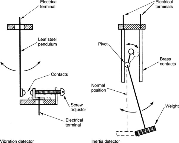
Vibration – a slender leaf of steel is suspended between two electrical contacts. Hammering or structural impact produces vibration in the pendulum, sufficient for the contacts to meet and complete a detector circuit. Adjustment allows for a variety of applications, e.g. where a road or railway is adjacent and intermittent vibration would occur.
Inertia – these respond to more sensitive movements than vibrations, so would be unsuitable near roads, railways, etc. They are ideal to detect the levering or bending of structural components such as window sashes and bars. A pivotal device is part of a closed circuit, where displacement of its weight breaks the circuit continuity.
Ultrasonic and Microwave Detectors
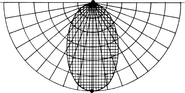
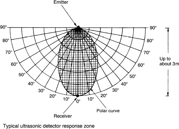
Ultasonic – the equipment is simply a sound emitter and a receiver containing a microphone and sound processor. The sounds are at a very high frequency of between 20 and 40kHz (normal hearing limit is about 15kHz). Direct and indirect (reflected) sound distribution from the emitter to the receiver adopts a pattern which can be plotted as a polar curve. If an intruder encroaches the curve the sound frequency will be disturbed. The receiver then absorbs the original frequency, the frequency reflected off the intruder and a mixture of the two. The latter is known as the ‘beat note’ and it is this irregularity which effects the detector circuit. Greatest detection potential is in the depth of the lobe; therefore this should be projected towards an entry point or a window.
Microwave – operates on the same principle as ultrasonic detection, except that extremely high radio waves are emitted at a standard 10.7GHz. Emitter and receiver occupy the same unit which is mounted at high level to extend waves over the volume of a room, warehouse, office or similar internal area. An intruder penetrating the microwaves disturbs the frequency which effects the detector circuit. Unlike ultrasonic detectors, microwave detectors are not disturbed by air currents, draughts and ultrasonic sounds from electrical equipment such as computers. They are therefore less prone to false alarms.
Otherwise known as an optical system, it uses a light beam from the infra-red part of the electromagnetic spectrum. This is imperceptible to the human eye. The system is based on a transmitter and receiver. The transmitter projects an invisible light beam at distances up to 300m onto a photo-electric cell receiver. An intruder crossing the beam will prevent the light from activating the cell. The loss of energy source for the cell effects an alarm relay. Even though the beam has extensive range, this system is not suitable for external use.
Atmospheric changes such as fog or birds flying through the beam can affect the transmission. Mirrors may be used to reflect the beam across a room or around corners, but each reflection will reduce the beam effectiveness by about 25%. Infra-red beams will penetrate glass partitions and windows, each pane of glass reducing the beam effectiveness by about 16%. The smarter intruder may be able to fool the system by shining a portable light source at the receiver. This can be overcome by pulsing the transmission, usually at about 200 pulses per second.

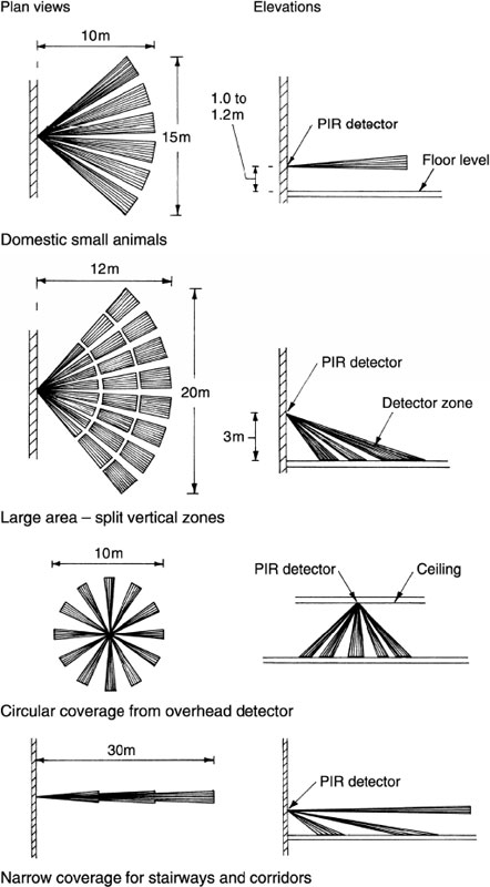
Passive Infra-red (PIR) Detector
These detectors use highly sensitive ceramic infra-red receivers to recognise radiation from a moving body. Wall-mounted detector units focus the radiation through a lens which contains curved facets to concentrate the radiation onto two sensors. Image variation between the sensors generates a small electrical differential to effect an alarm relay. These systems have enjoyed widespread application, not least in the domestic market. Units of lower sensitivity can be used where pets occupy a home. A battery back-up energy source covers for periods of mains power isolation. PIR detectors can be used with other devices in the same system, e.g. radio pocket panic buttons, pressure mats, magnetic reeds, etc. PIR beam patterns vary in form and range to suit a variety of applications, both externally and internally.

Typical patterns:
Lightning occurs as a result of electrostatic discharge between clouds or between a cloud and the ground. The potential is up to 100MV with the current peaking at about 200kA. The average current is about 20kA. The number of days that thunderstorms occur in the UK varies between five and 20 per year, depending on location. Consequently, some degree of protection to buildings and their occupants is necessary.
As the risk of lightning striking a particular building is low, not all buildings are protected. Houses have least priority and are rarely protected, but other purpose groups will be assessed by their owners and their insurers. This will be on the basis of height, contents, function, type of construction (extent of metalwork, e.g. lead roofing), likelihood of thunderstorms in locality, extent of isolation and the general topography. Even where a lightning protection system is provided it is unlikely to prevent some lightning damage to the building and its contents.
Function of a lightning protection system – to attract a lightning discharge which might otherwise damage exposed and vulnerable parts of a building. To provide a path of low impedance to an earth safety terminal.
Zone of protection – the volume or space around a conductor which is protected against a lightning strike. It can be measured at 45° to the horizontal, descending from the apex of the conductor. For buildings less than 20m in height the zone around a vertical conductor is conical. For buildings exceeding 20m, the zone can be determined graphically by applying a 60m radius sphere to the side of a building. The volume contained between the sphere and building indicates the zone. See next page for illustrations.

Air terminations – these are provided to intercept a lightning strike. No part of a roof should exceed 5m from part of a termination conductor, unless it is a lower level projection which falls within the zone of protection. Metallic components such as aerials, spires, cooling towers, etc. should be connected to a terminal. A part from specific apexes such as spires, air terminations are horizontal conductors running along the ridge of a pitched roof or around the periphery of a flat roof. If the roof is of sufficient size, a 20m × 10m grid or lattice of parallel terminations should be provided.
Down conductors – these provide a low impedance route from the air terminations to the earth terminal. They should be direct, i.e. vertical without bends and re-entrant loops. Spacing for buildings up to 20m in height is 1 per 20m of periphery starting at the corners and at equal distance apart. Buildings in excess of 20m height require 1 per 10m, at corners and equi-spaced. All structural steelwork and metal pipes should be bonded to the down conductor to participate in the lightning discharge to earth.
Fixing centres for all conductors:

Earth termination – this is required to give the lightning discharge current a low-resistance path to earth. The maximum test resistance is 10ohms for a single terminal and, where several terminals are used, the combined resistance should not exceed 10ohms. Depth of terminal in the ground will depend on subsoil type. Vertical earthing rods of 10 or 12mm diameter hard-drawn copper are preferred, but stronger phosphor-bronze or even copper-coated steel can be used if the ground is difficult to penetrate. Alternatively, a continuous horizontal strip electrode may be placed around the building at a depth of about 1 metre. Another possibility is to use the reinforcement in the building’s foundation. To succeed, there must be continuity between the structural metalwork and the steel reinforcement in the concrete piled foundation.
Ref. BS EN 62305-1 to 4: Protection against lightning.