
16 Alternative and Renewable Energy
Use of fuel as an energy resource is only cost effective and efficient if the building in which it is used is constructed to a high standard of insulation to resist heat or cool energy losses through the fabric. It is also dependent on high-efficiency systems and equipment, e.g. mechanical ventilation with heat recovery, condensing boiler. A legislative strategy for energy efficiency in new buildings and alterations to existing buildings is established by Building Regulations, Parts L1 and L2: Conservation of fuel and power.
Practical measures to ensure efficient use of fuel include double and triple glazing, airtightness and well-insulated external walls, floor and roof space. There are many construction techniques and procedures that can be used to apply these energy loss reductions through the external envelope. Numerous examples and applications are considered in some detail in the companion volume to this book, the Building Construction Handbook.
Where buildings are designed and constructed to limit fuel energy losses, consideration can also be given to on-site energy production as a viable alternative to reliance on conventional fossil fuels (coal, gas and oil). Alternatives are many and varied. On-site generation is dependent on geographical location, local climate, local utilities rates and availability of alternative fuels, e.g. biomass. Systems that qualify for government financial incentives such as ‘feed-in tariff’ are also an important factor.
Alternative energy – generally regarded as any type of usable energy that does not harm the environment, does not cause a decline in natural resouces and can be used as a replacement for fossil fuels, i.e. replaces fuels that have undesirable consequences when burnt.
Renewable energy – a natural, constantly replenished alternative energy resource including solar, wind, tidal, geothermal, hydro, biomass, biofuel and hydrogen.
Alternative and Renewable Energy
Power-stations that burn conventional fossil fuels such as coal and oil, and to a lesser extent natural gas, are major contributors to global warming, production of greenhouse gases (including CO2) and acid rain. Note: Acid rain occurs when the gaseous products of combustion from power-stations and large industrial plant combine with rainfall to produce airborne acids. These can travel hundreds of miles before having a devastating effect on forests, lakes and other natural environments. Current efforts to limit the amount of combustion gases in the atmosphere include:
CHP (cogeneration) and district heating systems (pages 165–168).
Condensing boilers (page 102).
Higher standards of thermal insulation of buildings (page 187 and Building Regulations, Approved Document L – Conservation of fuel and power).
Energy management systems (pages 183–185).
Recycling of waste products for renewable energy.
Renewable energy is effectively free fuel, but remarkably few of these installations exist in the UK. Other European states, particularly the Netherlands, Germany and Scandinavian countries, have waste segregation plant and selective burners as standard equipment at many power-stations. City domestic rubbish and farmers’ soiled straw can be successfully blended with conventional fuels to power electricity generators and provide hot water for distribution in district heating mains. Small-scale waste-fired units from 60kW up to 8000kW are standard installations in many continental domestic and commercial premises, but are something of a rarity in this country.
Renewable and other alternative ‘green’ energy sources are also becoming viable. These include:
Wind power.
Wind power and hydrogen-powered fuel cells.
Wave power.
Geothermal power.
Solar power.
Biomass or biofuels.
Anaerobic digestion and biogas.
Power generation from ‘green’ sources has already reduced CO2 emissions by 20% relative to 1990 figures. The UK government’s Low Carbon Transition Plan provides further objectives to reduce carbon emissions by 34% by 2020 and by 80% by 2050.
Refs. The Energy Act.
The Climate Change Act.
Renewable Energy – Feed-in Tariff
Feed-in tariff – A UK government initiative that provides a financial incentive for users of low-carbon heating installations. In principle, households and communities can claim payment for producing electricity even if they consume it on their own premises. A minimum payment of 3p/kWh can also be claimed for electricity exported to the market.
Eligible technologies –
Wind turbines up to 5MW.
Solar photovoltaic (PV) panels up to 5MW.
Hydro-power up to 5MW.
Anaerobic digestion.
Micro-combined heat and power (CHP).
The following calculation is a theoretical example based on a solar panel system with a pay-back tariff of 36.1p/kWh. This figure is for a new-build installation at 2010 to 2011 tariffs, but see Notes below.
Annual cost of electricity based on 3500kWh @ 12p/kWh = £420.
Typical cost of a PV solar power installation = £9620.
Typical annual power produced by the PV system is 2000kWh.
With the power used being free (12p/kWh) plus the pay-back of 36.1p/kWh, a saving of 48.1p/kWh is achieved.
2000kWh × 48.1p = £962 annual income.
Pay-back time on the capital cost = £9620 ÷ £962 = 10 years.
Thereafter the system is in profit with tariff payments guaranteed for a total of 25 years.
Note 1: A figure for inflation is not included with this calculation, but pay-back tariffs may be updated in line with the Retail Price Index.
Note 2: The Department of Energy and Climate Change (DECC) publish tables of tariff levels for different renewable energy installations (www.decc.gov.uk).
Note 3: Electricity cost at 12p/kWh is a typical figure. Some variation will be found between different suppliers.
Note 4: Pay-back tariffs are reviewed periodically by government; therefore figures given here are for calculation guidance only.
Anaerobic Digestion and Biogas
Anaerobic digestion – an established technology that has been used for centuries as a process for producing methane gas.
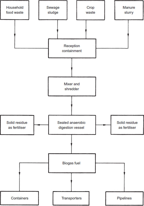
Process – biomass products such as food waste, energy crops, crop residue and manure are compounded and stored in sealed containers. Here in the absence of oxygen, naturally occurring micro-organisms digest the biomass and release methane gas that can be used as a fuel. After processing there remains a residual solid waste. This by-product is rich in nutrients and can be used as a fertiliser. Timber biomass products cannot be processed in this way because the microorganisms cannot break down the presence of lignin resin.
Biogas – composed mainly of methane (CH4, approx. 60%) and carbon dioxide (CO2, approx. 40%) with minor traces of other gases.
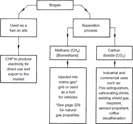
Anaerobic Digestion and Biogas Processing
The development of wind power as an alternative energy source is well advanced. However, it is dependent on the fickle nature of the weather and can only be regarded as a supplementary energy source unless the surplus power produced is stored – see page 673.

The principle is simple enough. Wind drives a propeller, which rotates a shaft through a gearbox to drive an electricity generator. The generator produces direct current, similar in concept to a much smaller bicycle dynamo. Designs include two- and three-blade variants, elevated to between 25 and 45 metres from ground level to central axis. Blades are usually made from laminated timber or glass fibre and manufactured to tip diameters of between 6 and 60 metres (25 to 30m is typical). Electricity output is difficult to define, but claims are made of 300kW in a 25mph wind from one generator. This is enough electricity for about 250 houses. A wind farm of say 20 generators in an exposed location could produce 20GW of electricity an hour averaged over a year.
Environmental issues – no release of carbon, sulphur or nitrogen oxides, methane and other atmospheric pollutants. Conservation of finite fossil fuels. Aesthetically undesirable and noisy.
Costs – produces electricity for a minimal amount. Foundation costs are very high to anchor the units against lateral wind forces and dynamic forces during rotation. The capital cost of generators and their installation costs must be calculated against the long-term savings and environmental benefits. The purchase costs of wind turbines commence at about £1200 per kW of output, with a life expectancy of about 30 years. The smallest of units may take about a week to install.
Savings – estimates vary from speculative projections to realistic comparisons. A small generator such as that used at Wansbeck General Hospital, Northumberland can produce up to 450kW daily. On a greater scale, it is anticipated that by the year 2025, up to 20% of the UK’s electrical energy requirements could be wind generated.

Wind is limited as a source of electrical power because of the unreliable nature of the weather. To use the potential of the wind effectively, it is necessary to store the energy generated when the wind blows and release it in response to demand.
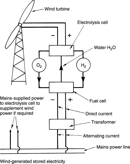
Instead of using the wind-generated electricity directly, it is used to electrolytically decompose water. This means separation of the hydrogen and the oxygen in water into different storage vessels. The stored hydrogen and oxygen are supplied to a fuel cell or battery in regulated amounts to produce a direct current. As the two gases combine they give water, which is returned to the electrolysis cell for reprocessing. Direct current is transformed to alternating current for compatibility with electricity distribution power lines.
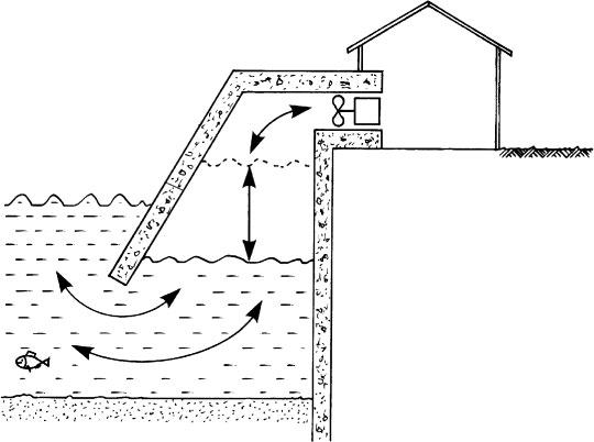
The energy potential in differing water levels has been exploited for centuries through water-mills and subsequently hydroelectric power. Another application is to build tidal barrages across major estuaries such as the Severn or Mersey. As the tide rises the water would be impounded, to be released back as the tide recedes, using the head- or water-level differential as a power source. This has been used to good effect since the 1960s at La Rance near St Malo in France.
Another application uses a series of floats moored in the sea to generate an electrical potential as each float moves with the waves. Attempts have also been made to use the floats to rotate a crankshaft. There are limitations with this, not least the obstruction it creates in the sea.
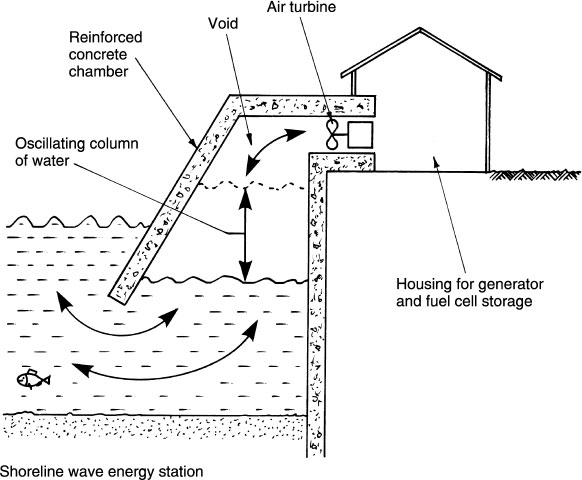
Power potential from waves can also be harnessed by using their movement to compress air in shoreline chambers. Air pressure built up by the wave oscillations is used to propel an air turbine/electricity generator.
This is otherwise known as ‘hot-dry-rock’ technology, a name which gives some indication of the energy source. Heat energy is produced by boring two or more holes into the granite fissures found at depths up to 4·5 miles (7·2km) below the earth’s surface. Cold water pumped down one borehole and into the fissures converts into hot water or steam which is extracted from the other borehole(s). The hot water can then be used directly for heating or it can be reprocessed into steam to drive turbines and electricity generators on the surface.
Enormous quantities of heat are believed to exist in underground rock formations throughout the world. New Zealand and Iceland are well known for having hot volcanic springs and established use of naturally occurring hot water from geysers. In the UK there are a few isolated examples of spas, but the greatest potential lies below the impermeable granite substrata in the south-west corner of England. This concentrates in Cornwall and ranges up to Dartmoor and the Scilly Isles. Geological surveys suggest that the heat energy potential here is twice that elsewhere in the UK. Since the 1970s the centre of research has been at Rosemanowes Quarry, near Falmouth. Indications from this and other lesser sites in the locality are that there may be enough geothermal energy in the West Country to provide up to 20% of the UK’s electricity needs. Exploration by boreholes into aquifers in other parts of the country have met with some success. In Marchwood, Southampton, water at over 70°C has been found at depths of less than 2km. However, this resource was found to be limited and not cost effective for long-term energy needs (see next page).
Exploitation of hot water from naturally occurring springs is not new. All over the world there are examples of spas which are known to have been enjoyed since Roman times. More recently in the early 1900s, a natural source of steam was used to generate electricity in Italy. Now it is very much a political and economic decision as to whether it is cost effective to expend millions of pounds exploiting this possibly limited source of heat energy.
Geothermal Power – Installation
Location – during the 1970s and early 1980s, site boreholes were sunk at the Marchwood power-station site on Southampton Water and in Southampton centre.
Results – the second borehole near the city shopping centre provided greatest potential, with a water temperature of 76°C at 1800 metres.
Initial outcome – the Department of Energy considered the resource of limited economic value to make a significant contribution nationally.
Later outcome – Southampton City Council took the initiative to form a partnership with Utilicom, a French-owned energy management company, to develop a local district heating scheme. Utilicom’s parent companies, IDEX and STREC, had considerable experience in operating geothermal district heating systems around Paris. In 1986 Utilicom and Southampton City Council formed the Southampton Geothermal Heating Company (SGHC).

Energy use – the geothermal resource provides about 20%, with fuel oil and natural gas approximately 10% and 70%, respectively. A chilled water facility is also provided by the heat pump.
Clients – mainly corporations and commercial premises, although some housing estates and apartment blocks are included.
Commendation – received The Queen’s Award for Enterprise: Sustainable Development 2001.
Micro-combined Heat and Power (CHP)
Micro-CHP or microgeneration – an electricity generator at the point of use, independent of a mains grid supply of electricity, combined with a water heater. A micro-CHP unit is a gas-fired engine used to produce electricity with the heat energy used for domestic hot water requirements. Comparisons can be made with the power unit in a motor vehicle, except that the fuel energy conversion objective differs and any CHP function is secondary and uneconomical.
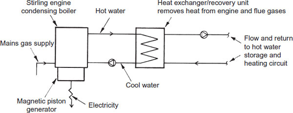
Function – fuelled by mains gas, although other fuel options are being developed. Comprises in one unit a condensing boiler to heat water and a Stirling engine to produce electricity. The Stirling engine is old technology, its invention dating back some 200 years. Motion occurs in response to combustion of gas to heat water, as explained:
Helium in a sealed compartment is warmed as the gas burner heats water.
Expansion of helium pushes down a magnetic piston.
Cool water in the boiler absorbs the heat, allowing the helium to contract and the piston to rise.
Heated water circulates through a heat exchanger to be replaced by cooler water in the return circuit.
The magnetic piston moves up and down at 50 cycles/sec. between a generator coil, producing electricity by electromagnetic induction.
For every 6kW of thermal energy produced, about 1kW of electricity is generated.
Units are approximately 90% efficient and use 35% less primary energy, as the waste heat is used effectively and there are no transmission losses.
Operating principle –
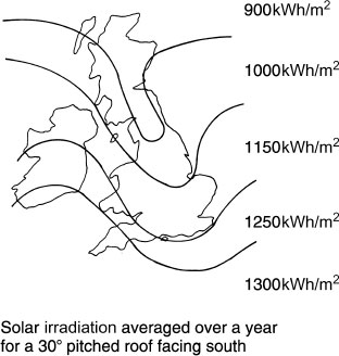
The potential of solar energy as an alternative fuel is underrated in the UK. It is generally perceived as dependent solely on hot, sunny weather to be effective. In fact it can be successfully used on cloudy days, as it is both the direct and diffused solar irradiation which is effective. The average amount of solar irradiation falling on a south-facing inclined roof is shown to vary between about 900 and 1300 kWh/m2 per year depending on the location in the UK.
Note: 1 kWh = 3.6 MJ.
The reluctance to accept solar panels in this country is understandable. The capital outlay is quite high and even though it is possible to achieve up to 40% of the average household’s hot water requirements from solar energy, the pay-back period may be in excess of 10 years. It could also be argued that the panels are visually unattractive. The typical installation is shown on page 117. It has a flat plate ‘black radiator’ solar panel to absorb solar energy in water, which is transferred for storage in an insulated cylinder. From here it supplements hot water from a conventional boiler source. This application is also suitable for heating swimming pools.
An improvement uses collectors inside clear glass vacuum cylinders. These ‘evacuated tube collectors’ are capable of absorbing more heat at low levels of light. Other types of solar panel which can be used to power batteries or fuel cells include the photovoltaic system. This uses expensive crystalline silicon as a power generator. A less expensive alternative is amorphous silicon. Although less efficient, it is still capable of providing a trickle feed to batteries.
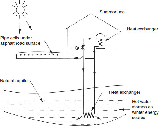
The flat plate ‘black radiator’ solar panel referred to on the previous page is not limited to roof-top applications. Any reasonably large, flat black surface can be effective. For example, asphalted road surfaces are very effective solar energy collectors. With piped water circuits installed close to the road surface, summer heat transfer to the sub-surface coils can be pumped through heat exchangers in adjacent buildings to provide hot water in storage. In addition, if the geology permits, the hot water generated at the surface can be pumped deep into the ground through heat exchangers located in an aquifer, thereby creating a heat store for winter use.
Photovoltaic (PV) cells use light as a source of energy. A small-scale application is to handheld calculators with an integral PV window as the power source instead of a conventional dry cell battery. On the larger scale and as a viable means for producing electrical energy in buildings, PV cells are arranged into a large array of panels that can be located on the roof slope. With sufficient output, surplus electricity can be stored for use during periods of limited or no light and may also be traded with the grid supply.
Principle – requires only daylight not direct sunlight to generate electricity. Output varies with the intensity of light. A PV cell processes natural light into electrical energy through the intermediary of a semiconductor. Suitable semiconductors include amorphous silicon, gallium arsenide, copper indium diselenide and cadmium telluride. Crystalline silicon is generally regarded as the most cost effective. Light received by the cell produces an electric field over its layers to generate a direct current of about 12 volts.
Cell function – a PV cell comprises two thin layers, one with a positive charge and the other a negative charge. Light hitting the cell energises electrons that move towards the layer faces to produce an electrical imbalance between the layers, as shown in the diagram below.
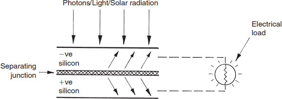
Potential output in the UK for a typical south-facing roof-top panel of 10–15m2 can be about 750kWh of electrical energy. This is approximately one-quarter of the annual requirements for a typical three- to four-bedroom family house.
Systems may be grid connected or independent:
Grid connected – at times when only a limited amount of electrical energy is required, for example, during a factory closure for maintenance, surplus energy from a PV installation can be used to supplement and be traded with the general supply from the national grid. Conversely, the grid can supplement the limitations of a PV system, particularly at night when there is no natural light source to activate the cells.
Independent – suitable for use with isolated buildings detached from the grid. Rechargeable solar batteries will be required for storing electrical energy for use when the PV system is inactive, i.e. at night. This can be particularly beneficial in agricultural and farm buildings. Smaller applications include traffic information boards, advertising and car-park displays, navigation buoys and the many situations applicable to developing parts of the world that are without a conventionally generated mains supply.
Principle of PV installation –

Biomass is current terminology for the combustion of traditional fuels such as wood, straw and cow dung. The difference is that today we have the facility to process and clean the waste products. Gas scrubbers and electrostatic precipitators can be installed in the flues to minimise atmospheric pollution. Intensive farming methods produce large quantities of potentially harmful residues, including straw and chicken droppings. The latter combines with wood shavings and straw from the coops. Instead of burning these as waste, they can be reprocessed. A pioneer scheme at Eye in Suffolk burns the waste in a 10MW steam turbine electricity generator and sells the ash as an environmentally friendly fertiliser. This has the additional benefits of:
Eliminating the traditional unregulated burning of farm waste which contaminates the atmosphere with carbon dioxide.
Destroying the harmful nitrates which could otherwise be released into the soil.
Destroying the potential for methane generation from decomposition. When this is released into the atmosphere it is far more active than carbon dioxide as a greenhouse gas.
Farm wastes can also be used to produce methane gas for commercial uses. The waste is processed in a controlled environment in large tanks called digesters. The gas is siphoned off and used for fuel, while the remains are bagged for fertiliser.
The potential for forest farming wood as a fuel for power generation is also gaining interest. Trees naturally clean the atmosphere by absorbing carbon dioxide. However, when they die, they rot, releasing as much carbon dioxide as is absorbed during growth and a significant amount of methane. By controlled burning the carbon dioxide is emitted, but the gains are destruction of the methane and an economical, sustainable fuel supply.
For applications, see pages 210 to 212.
Underground Coal Gasification (UCG)
UCG is not a new concept as shown by references to William Siemen’s research from the mid-19th century. The earliest recorded experimental work is that undertaken by the Scot, William Ramsay, during the early years of the 20th century. Since then, development has been limited to periodic investigations at various sites throughout the world. Concentrated efforts have been cost restrained and at times curtailed when new finds of natural gas and oil resources have reduced the importance. However, that situation cannot be sustained, especially with the trend for increasing energy demands for industrial and commercial needs and from population expansion. By 2030 it is estimated that the world will need 50% more energy than that required in 2010. Therefore, the urgency for alternative fuel resources indicates that UCG is a viable development.
Principle of UCG – to convert unworked coal into a combustible gas that is processed to release CO2 and to create a source of clean energy. Coal waste/ash remains underground.

The most important part of the process is to remove the CO2 from the generated gases. This is known as carbon capture and storage. The technology exists and is being developed.
From the perspective of the UK, estimates of coal resources vary but most agree that no more than 25% has ever been extracted. The remainder is not cost viable to remove, but could hold considerable potential for UCG.
Carbon Capture and Storage (CCS)
Combustion of fossil fuels releases excessive amounts of carbon dioxide into the atmosphere. From power-stations the potential damage to the atmosphere is unacceptable. Considerable research has been undertaken to develop methods that control the CO2 by cleaning and containment.
CCS commences by blasting the fuel with oxygen and steam at a temperature of 700° C. This is undertaken in a ‘gasifier’ to produce carbon monoxide and water, which is then converted to carbon dioxide and hydrogen. The CO2 is cooled until it becomes liquid. Thereafter it is pumped into underground storage voids that remain from previous extraction of natural gas and oil below the sea. Inland depleted coalmines have also been considered as suitable storage spaces.
The CO2 would be stored indefinitely. A controversial issue, as there is no certainty that the gas would not seap out, even from hundreds of metres below the surface.

A variation of CCS processes the combustion products by ‘scrubbing’. This extracts and separates the CO2 from the other flue gases before they are released into the atmosphere. Thereafter the CO2 is transported and stored as previously described.
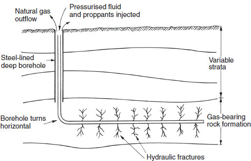
Induced hydraulic fracturing – otherwise known as hydrofracking or just simply, fracking. Not alternative energy, but an alternative means for extraction of oil and gas contained in rock formations hundreds of metres below the surface. It originated from experimental work in the late 1940s, but diminishing accessible fuel resources have promoted much greater use since the 1990s.
Process – a deep well bored into rock formations that contain hydrocarbon fuel resources such as coal and shale gas. At selected depths which can be some 2000 metres, the bore continues horizontally. Pressurised fluid is injected into the horizontal bore to crack the rock formation. The fluid contains sand or ceramic granular proppants that remain to hold open the cracks. Pressurisation ceases and a mix of fluid and gases flow into the well for extraction.
Environmental concerns –
Possibility of contaminating ground water.
Surface migration of gases, oils and fracturing chemicals, leading to contamination of the atmosphere, surface water and soil.
Earth tremors (minor recordings occurred near Blackpool in 2011).