
2 Cold Water and Supply Systems
Rain Cycle – Sources of Water Supply
Acidity and Alkalinity in Water
Storage and Distribution of Water
Direct System of Cold Water Supply
Indirect System of Cold Water Supply
Water Conditioning and Treatment
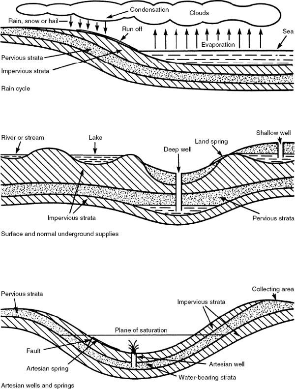
Rain Cycle – Sources of Water Supply
Water is the essence of life.
Surface sources – lakes, streams, rivers, reservoirs, run off from roofs and paved areas.
Underground sources – shallow wells, deep wells, artesian wells, artesian springs, land springs.
Acidity and Alkalinity in Water
Acid – a substance containing hydrogen which can be replaced by other elements. Litmus paper in the presence of acidic water turns red. Alkali – a substance which will neutralise acid by accepting its hydrogen ions (H+). Litmus paper in the presence of alkaline water turns blue.
More accurate definitions can be obtained by using hydrochemical electric metres. These measure the amount of hydrogen ions (H+) in a relative proportion of water. This measure of acidity or alkalinity in solution is referred to numerically from 0–14 as the pH value.
pH < 7 indicates acidity
pH > 7 indicates alkalinity
pH = 7 chemically pure
The quality of processed water is unlikely to be pure due to contamination at source.
Rainwater – contaminated by suspended impurities as it falls through the air. These impurities are principally carbon dioxide, sulphur and nitrous oxides originating from domestic flue gases and industrial manufacturing processes. The mixture of these impurities and rainfall produces ‘acid rain’, an occurrence frequently blamed for the destruction of plant life.
Surface and substrata water sources – contaminated by dissolved inorganic materials such as calcium, magnesium and sodium. These are responsible for water hardness as described on pages 44–46. Organic matter from decaying vegetation, animals and untreated waste water can also contaminate ground water supplies. These are normally associated with ammonia compounds in the water or bacteria. Certain types of bacteria present in water can be responsible for outbreaks of typhoid, cholera and dysentery. Chlorination, as described on page 23, is applied to filtered water to destroy any remaining bacterial microbes before general distribution through service reservoirs and mains.
The following table shows the quantity of pollutant microbes present during the stages of water processing, as described on pages 22–24:
Source/process |
Typical pollutant microbe count per litre |
|---|---|
River |
41000 |
Impounding reservoir |
1500 |
Primary filter |
500 |
Secondary filter |
50 |
Chlorination |
0 |
Service reservoir |
0 |
Distribution main |
0 |
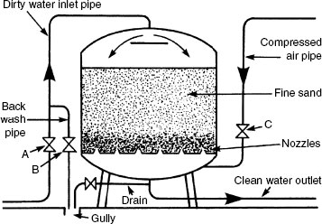
Pressure filter – rate of filtration 4 to 12m3 per m2 per hour. To backwash, valve A is closed and valves B and C opened. Compressed air clears the sand of dirt. Diameter = 2·4m.
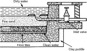
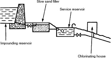
Slow sand filter bed – rate of filtration 0·2 to 1·15m3 per m2 per hour. Filter beds can occupy large areas and the top layer of sand will require removal and cleaning at periodic intervals.
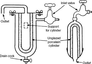
Small domestic filter – the unglazed porcelain cylinder will arrest very fine particles of dirt and even micro-organisms. The cylinder can be removed and sterilised in boiling water for 10 minutes.
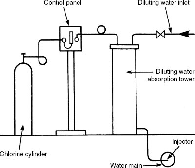
Sterilisation by chlorine injection – water used for drinking must be sterilised to make it completely free of living micro-organisms. Chlorine is generally used for this purpose. A minute quantity of gaseous chlorine (Cl) or sodium hypochlorite (NaOCI) in solution, commonly known as bleach, (0.1 to 0.3ppm), is added after filtration in absorption towers or small covered reservoirs known as contact tanks. The process takes about two hours before the treated water is released into the water mains or pumped to service reservoirs.
Fluoridation – an additive introduced to drinking water by some supply authorities. Unlike chlorine, it is not added to make supplies safe. The objective is to reduce tooth decay in young children, as fluoride is known to make the enamel covering of their teeth tougher. When added, the amount is between 0.5 and 1 mg per litre of water (0.5 to 1.0ppm). This amount is not enough to affect the appearance, taste or smell of water. Arguments against using fluoride are the availability of fluoride toothpastes and that it is wasteful to treat water supplies when over 99% of water is used for other purposes than cleaning teeth. Others include the suggestion that too much exposure can cause staining and mottling of the teeth, even bone disorders and other health issues.
Storage and Distribution of Water
Gravitational distribution – the water from upland gathering grounds is impounded in a reservoir. From this point the water is filtered and chlorinated before serving an inhabited area at lower level. There are no pumping costs.
Pumped distribution – water extracted from a river is pumped into a settlement tank, subsequently filtered and chlorinated. Pump maintenance and running costs make this process more expensive than gravity systems.

Ring main distribution – water mains supplying a town or village may be in the form of a grid. This is preferable to radial distribution as sections can be isolated with minimal disruption to the remaining system and there is no more opportunity for water to maintain a flow.

Disinfection – the process of inactivating bacterial or viral cells, either by destruction or by eliminating their pathogenic properties.
Off-line, system not in use –
Oxidising disinfectants including sodium hypochlorite (chlorination) and chlorine dioxide. Bromine and ozone can be used to treat water in industrial processing plants. Water systems containing these and chlorine disinfectants at concentrations greater than that approved in drinking water (see Note) should be fitted with a backflow prevention device (see page 55).
Thermal disinfection, also known as pasteurisation, requires stored water to be maintained between 60°C and 70°C. This may be acceptable for industrial processes, but for domestic use and washing facilities in general it is impractical due to the possibility of scalding at hot water outlets.
On-line, system active –
Either continuous dosing with chlorine additives (see Note) or an electrolytic treatment as described on page 51.
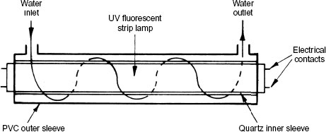
Ultraviolet – exposing water to an UV light with a dedicated output of 254 nanometer wavelength. An irradiating process that damages the DNA of bacterial and viral cells, inactivating them and preventing their reproduction. Of limited dispersal, therefore most suited to small circulation installations such as garden ponds.
Note: Water that contains disinfectants with concentrations in excess of those acceptable for drinking purposes is known as Category 3 quality, as defined under Schedule 1 of the Water Supply (Water Fittings) Regulations. See page 27.
Water for drinking, washing or for food preparation must be of a wholesome quality. Reclaimed greywater, captured or harvested rainwater and water abstracted directly from wells, springs, boreholes and other accessible water courses is regarded as less than wholesome, but it can be used for other purposes. Pipework and equipment used to convey less than wholesome water must be appropriately marked and identified as such. All supplies are to be reliable and of sufficient pressure and flow rate to operate end use appliances efficiently.
Definitions:
Wholesome – water complying with regulations made under Section 67 (Standards of wholesomeness) of the Water Industry Act. The term wholesome is often used instead of potable, i.e. fit to drink. Category 1.*
Greywater – water from showers, baths, taps and washing machines, collected, treated, stored and recycled as an alternative to using wholesome water for sanitary appliances (WCs) and for outdoor uses (gardening). Category 5.*
Captured or harvested rainwater – rainwater collected and stored from roofs and other external surfaces. An old technology that has evolved to become integral with contemporary building design. Used for flushing WCs, washing machines and garden watering (see pages 353 to 356). Category 5.*
*Water Supply (Water Fittings) Regulations – see next page.
Refs. Building Regulations Part G, Approved Document G1: Cold Water Supply.
BS 8525–1: Greywater systems. Code of practice.
Water Regulations Advisory Scheme (WRAS) Guidance Note 0–02–05.
In recent years water consumption in the UK has amounted to about 150 litres per person per day. Each household uses about 100,000 litres (100 m3) per year.
Total UK annual consumption is about 16.5 billion m3 with some 13.5 billion m3 attributed to non-domestic users.
Data source: Office for National Statistics.
Schedule 1 of the Water Supply (Water Fittings) Regulations, categories of fluids:
Category 1 – wholesome water supplied by an approved water undertaker that complies with standards of wholesomeness defined in Section 67 of the Water Industry Act. Suitable for domestic consumption and for food preparation purposes. Obtained directly from the water company’s main.
Category 2 – water that is not considered to be a health hazard, although it is not suitable for drinking. Water originating from a category 1 source that has changed in temperature, taste, smell or appearance. Some examples are water that has been subjected to a rise in temperature in a hot water system, mixed cold and hot water and domestic water softened by salt regeneration.
Category 3 – water that is possibly a health hazard, therefore unsuitable for drinking as it may contain low concentrations of toxic additives. These include ethylene glycol (antifreeze) that may be used in solar systems of hot water supply and sodium hypochlorite disinfectants. Also applies to the water in primary hot water and heating circuits (with or without additives) and commercial water softening by salt regeneration.
Category 4 – water that is a distinct health hazard due to concentrations of toxic substances or bacterial or viral microorganisms, e.g. Legionnaires‘ disease. Unsuitable for drinking or for any domestic uses. Includes water in non-domestic hot water and heating circuits, treated water from processes other than salt regeneration, water from commercial dishwashers and washing machines, water containing herbicides, pesticides and other high concentrations of chemicals and carcinogenic substances.
Category 5 – the highest level of fluid toxicity and contamination. A serious health hazard from concentrations of pathogenic (disease-carrying) organisms, including bacteria and viruses such as salmonella and cholera. Water containing radioactive and very toxic substances. Many situations may apply, including poorly or unmaintained food-processing machinery, sanitary facilities and medical equipment. Recycled greywater (waste water from basins, baths, shower trays, dishwashers and washing machines) is in this category.
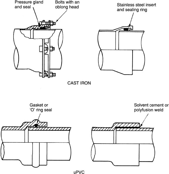
Water mains have been manufactured from a variety of materials. The material selected must be compatible with the water constituents, otherwise corrosion and decomposition of the pipes may occur. Contemporary materials which suit most waters are ductile cast iron and uPVC. The water undertaking or authority must be consulted prior to laying mains to determine suitable materials, laying techniques and pipe diameter. Firefighting and hydrant requirements will prioritise the criteria with a minimum pressure of 30m head (300kPa) from a 75mm diameter pipe supplied from both ends, or 100mm diameter from one end only. Bedding of mains is usually a surround of shingle to accommodate any movement. uPVC pipes are pigmented blue for easy identification in future excavations and cast iron has a blue plastic tape attached for the same reason.
Refs. BS EN 545: Ductile iron pipes, fittings, accessories and their joints for water pipelines.
BS EN ISO 1452’ 2: Plastics piping systems for water supply and for buried and above-ground drainage and sewerage under pressure.
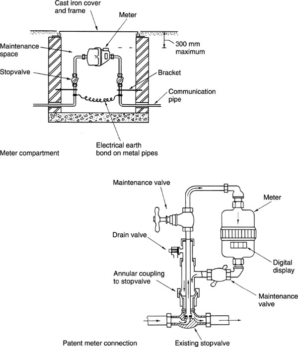
The water authority requires at least seven days’ written notice for connection to their supply main. The main is drilled and tapped live with special equipment, which leaves a plug valve ready for connection to the communication pipe. A goose neck or sweeping bend is formed at the connection to relieve stresses on the pipe and valve. At or close to the property boundary, a stop valve is located with an access compartment and cover at ground level. A meter may also be located at this point. The communication and supply pipe should be snaked to allow for settlement in the ground. During warm weather, plastic pipes in particular should be snaked to accommodate contraction after backfilling.

Water meters are installed at the discretion of the local water authority. Most require meters on all new build and conversion properties, plus existing buildings which have been substantially altered. In time, in common with other utilities, all buildings will have metered water supply. Meters are either installed in the communication pipe, or by direct annular connection to the stopvalve. If underground location is impractical, the water authority may agree internal attachment to the rising main.
Cold Water Supply–Efficiency in Use
Water is a finite resource with provision determined very much by the fickle nature of the weather. In the UK, demand from an increasing population is imposing considerably on this limited and unreliable resource. In addition, rising levels of affluence and higher standards of living create expectations for luxury goods such as whirlpool baths, power showers, hot tubs and possibly swimming pools in some high specification modern homes. Promotion of water use efficiency is therefore paramount to management of demand.
Fixed sanitary appliances must be designed to prevent undue consumption of water. This places an emphasis on sanitaryware and equipment manufacturers to produce end-use fittings that function efficiently and economically (see page 43) .
Building Regulation 17K and associated Approved Document G2 set a target for consumption of wholesome water not exceeding 125 litres per person per day to include a fixed factor of 5 litres per person per day outdoor use. Tables and charts* are used to calculate consumption based on fitment manufacturers’ flow rate data. The use of greywater and rainwater is encouraged by offsetting this against consumption of wholesome water.
Water meters – average home consumption is some 15% less than homes without a meter. Meter use is not a legal requirement, although it is generally standard with all newly built dwellings. Just over one-third of UK homes have a meter with an expectation of half by 2015.
Refs. WRAS Approved Water Fittings and Materials Directory.
Department for Communities and Local Government (DCLG) Code for Sustainable Homes.
Building Regulation 17K (Water efficiency of new dwellings).
Building Regulations Part G, Approved Document G2: Water Efficiency.
*DCLG Water Efficiency Calculator for New Dwellings.
National House Building Council (NHBC) Water efficiency in new dwellings.
The globe-type stopvalve is used to control the flow of water at high pressure. To close the flow of water the crutch head handle is rotated slowly in a clockwise direction gradually reducing the flow, thus preventing sudden impact and the possibility of vibration and water hammer.
The gate or sluice valve is used to control the flow of water on low-pressure installations. The wheel head is rotated clockwise to control the flow of water, but this valve will offer far less resistance to flow than a globe valve. With use the metallic gate will wear and, on high-pressure installations, would vibrate.
The drain valve has several applications and is found at the lowest point in pipe systems, boilers and storage vessels.
For temperatures up to 100°C valves are usually made from brass. For higher temperatures gunmetal (a type of bronze) is used. Brass contains 50% zinc and 50% copper. Gunmetal contains 85% copper, 5% zinc and 10% tin.

Refs. BS 5154: Specification for copper alloy globe, globe stop and check, check and gate valves.
BS EN 12288: Industrial valves. Copper alloy gate valves.
Float valves are automatic flow control devices fitted to cisterns to maintain an appropriate volume of water. Various types are in use. The diaphragm type is the least noisy as there is less friction between moving parts. The Portsmouth and Croydon-type valves have a piston moving horizontally or vertically respectively, although the latter is obsolete and only likely to be found in very old installations. Water outlets must be well above the highest water level (see page 53) to prevent back siphonage of cistern water into the main supply. Nozzle diameters reduce as the pressure increases. High-, medium- and low-pressure valves must be capable of closing against pressures of 1380, 690 and 275kPa respectively. Produced from copper alloy or ABS plastic (acrylonitrile butadiene styrene) depending on application.
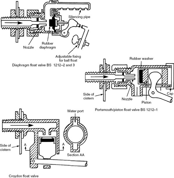
Ref. BS 1212: Float operated valves.
The pillar tap is used to supply water to basins, baths, bidets and sinks. Combined hot and cold pillar taps are available with fixed or swivel outlet. The outlet of these taps must be bi-flow, i.e. separate waterways for hot and cold water to prevent crossflow of water within the pipework.
The bib tap is for wall fixing, normally about 150mm above a sanitary appliance. The ‘Supatap’ bib tap permits a change of washer without shutting off the water supply. It is also available in pillar format. Quarter-turn taps are easy to operate by hand or elbow, and therefore are suitable for use by the disabled and medical practitioners.

Ref. BS EN 200: Sanitary tapware.
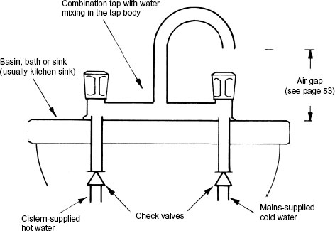
The blending of two supplies of water at different temperatures using a combination tap with a common outlet can be effected within the body of the tap, or through separate waterways to the spout as shown below.

Where there is an imbalance of pressures, typical of blending high-pressure mains-supplied cold water with lower pressure cistern-supplied hot water in the body of a combination tap, a check valve should be provided on each supply. These are required to prevent cross-contamination by the higher pressure cold flowing into the hot water supply system and, under fault or vacuum conditions, the hot flowing into the cold water supply.
Operation – a quarter-turn (90°) valve with a lever control handle. The lever is attached by spindle to a ball with a central hole that aligns with the adjacent pipe bore. When fully open, water flows unopposed by internal components and directional changes. Pressure and flow losses are minimal.
Application – an on/off isolating service valve used for system and appliance maintenance. ‘Every inlet to a storage cistern, combined feed and expansion cistern, WC flushing cistern or urinal flushing cistern shall be fitted with a servicing valve on the inlet pipe adjacent to the cistern.’ Extract from The Water Supply (Water Fittings) Regulations.
Size and function – generally relatively small, up to 75mm nominal bore. Functionally simple, durable and rarely requiring attention. Produced with a chromium-plated brass or ceramic ball that rotates against a seating of PTFE to achieve an effective seal. Valve body is typically a chromium-finished copper alloy known as DZR or brass.

Operation – a quarter-turn (90°) valve used with piped supplies of over 50mm nominal bore, although diameters considerably in excess of this are available. Direct rotation of a centrally positioned disc is by lever handle or indirectly by wheel through a reduction gearbox. The latter is essential with larger diameter valves. Both types can also be operated by motorised actuators.
Application – because of their size, non-domestic situations, particularly those associated with process plant as an end-of-line drainage valve. May also be used with water waste treatment, chemicals, food processing and as flow control for gas-, air- and gravity-fed powders.

Produced from copper and aluminium alloys, ductile and cast iron. An EPDM (ethylene propylene diene monomer) synthetic rubber, PTFE (polytetrafluorethylene) or nitrile rubber lining provides for an effective seal.
Copper pipes may be jointed by bronze welding. Non-manipulative compression joints are used on pipework above ground and manipulative compression joints are used on underground pipework. The latter are specifically designed to prevent pipes from pulling out of the joint. Push-fit joints are made from polybutylene. These provide simplicity of use and savings in time. Capillary joints have an integral ring of soft solder. After cleaning the pipe and fitting with wire wool and fluxing, heat application enables the solder to flow and form a joint. Solder alloy for drinking water supplies must be lead free, i.e. copper and tin.
The Talbot joint is a push-fit joint for polythene pipes. A brass ferrule or support sleeve in the end of the pipe retains the pipe shape.
Threaded joints on steel pipes are sealed by non-toxic jointing paste and hemp or polytetrafluorethylene (PTFE) tape. A taper thread on the pipe will help to ensure a watertight joint. Union joints permit slight deflection without leakage.
Lead pipes are no longer acceptable due to the risk of poisoning.

Polyethylene (Polythene) Water Pipes
Categories of polythene (also referred to as alkathene) and fittings suitable for cold water supplies:
Blue polythene – a medium density polythethylene (MDPE) for use with underground drinking water supplies. Pigmented blue for ease of identification in excavations. Produced in outside diameters from 20mm up to 63mm (nominally 15 to 52mm internal diameter). Not suitable for above-ground applications unless protected, as it can be affected by direct sunlight.
Black polythene – an MDPE for use with above-ground drinking water supplies. Pigmented black to differentiate from blue underground pipe. Produced to the same diameter specifications as for blue MDPE. Resistant to ultraviolet direct sunlight.
MDPE coiled standard lengths – 25, 50 and 100 metres.
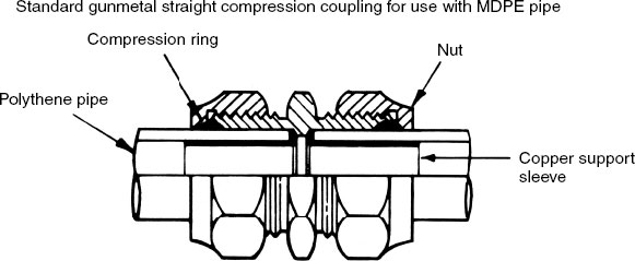
Note: Copper alloy pipe fittings/couplings to be made from gunmetal, an alloy of copper (85%), tin (10%) and zinc (5%).
Refs. BS EN 12201 series: Plastic piping systems for water supply.
Polyethylene (PE).
BS EN 1254–3: Copper and copper alloys. Plumbing fittings.
Fittings with compression ends for use with plastic pipes.
Linseed oil ‘white’ jointing paste – a blend of linseed oil and clay which surface hardens to form a strong, dense joint. Used mainly on threaded steel pipework with fibrous hemp reinforcement between the threads. Microbial action can break down the linseed component and the hemp can degrade, therefore not recommended for use on drinking water supplies. Synthetic reinforcement fibres are more durable. Unreinforced paste is suitable for gas and steam pipe lines. Graphite is sometimes added to the paste for use on steam, as this eases joint breakage when undertaking maintenance and alterations.
Silicone oil jointing paste (acetosilane). Combined with synthetic reinforcement fibres, this compound may be used on drinking water supplies. Also suitable for jointing hot water and gas pipes. Non-setting, non-cracking and flexible, so easily broken for maintenance and alterations.
BS 6956–5: Jointing materials and compounds.
Resin-based compounds – these are specified for chemical and oil pipe joints where the liquid conveyed may contain solvents which could weaken oil-based sealants. Resin and fillers are mixed with a catalyst and, after application to pipe threads, tightened joints will require time to set.
PTFE tape – wound into threads prior to joint tightening. Chemical and temperature resistant with an element of flexibility. Suitable for water and gas pipe joints. Also available as a liquid, but relatively expensive.
BS 7786: Specification for unsintered PTFE tapes for general use.
BS EN 751–3: Sealing materials for metallic threaded joints– – –.
Solders and fluxes – the established method for economically jointing copper pipe and fittings. Solder types:
29% tin + 71% lead. Traditionally used for all joints but now prohibited on drinking water supplies because of the lead content. Melting point = 210°C.
63% tin + 37% lead. Bit solder for electronic applications. Melting point = 185°C.
99% tin + 1 % copper. Lead-free for drinking water supplies. Melting point = 235°C.
BS 6920: Suitability of non-metallic products in contact with water– – –.
BS EN ISO 9453: Soft solder alloys. Chemical compositions and forms.
Fluxes are classified as passive or self-cleaning. Available in liquid or paste format and function by preventing cleaned surfaces from tarnishing under heat. Passive fluxes do not contain any free acid and will require heat application to effect cleaning. These are water-soluble organic fluxes and are preferred by gas companies due to the flux’s non-corrosive properties. Water-soluble fluxes are preferred for use with lead-free solders and are easily cleaned from finished joints. Self-cleansing fluxes contain an acid to clean tarnished copper as soon as applied. Heat application accelerates the process. Any flux residue must be cleaned from the pipe surface to prevent corrosion. Deposits internally are removed by flushing the system.
Direct System of Cold Water Supply
For efficient operation, a high-pressure water supply is essential particularly at periods of peak demand. Pipework is minimal and the storage cistern supplying the hot water cylinder need only have 115 litres capacity. The cistern may be located within the airing cupboard or be combined with the hot water cylinder. Drinking water is available at every draw-off point and maintenance valves should be fitted to isolate each section of pipework. With every outlet supplied from the main, the possibility of back siphonage must be considered.
Back siphonage may occur when there is a high demand on the main. Negative pressure can then draw water back into the main from a submerged inlet, e.g. a rubber tube attached to a tap or a shower fitting without a check valve facility left lying in dirty bath water.

Notes: (1) Servicing valves to be provided on supply pipes to storage and flushing cisterns. (2) Copper tube pipe sizes shown.
Ref.: The Water Supply (Water Fittings) Regulations 1999.
Indirect System of Cold Water Supply
The indirect system of cold water supply has only one drinking water outlet, at the sink. The cold water storage cistern has a minimum capacity of 230 litres, for location in the roof space. In addition to its normal supply function, it provides an adequate emergency storage in the event of water main failure. The system requires more pipework than the direct system and is therefore more expensive to install, but uniform pressure occurs at all cistern-supplied outlets. The water authorities prefer this system as it imposes less demand on the main. In addition, with fewer fittings attached to the main, there is less chance of back siphonage. Other advantages of lower pressure include less noise and wear on fittings, and the opportunity to install a balanced pressure shower from the cistern.
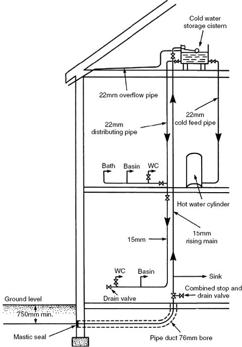
Notes: (1) Servicing valves to be provided on supply pipes to storage and flushing cisterns. (2) Copper tube pipe sizes shown.
Ref.: The Water Supply (Water Fittings) Regulations 1999.
Water Supply – Water-efficient Products
The Code for Sustainable Homes, published by the UK government, sets water consumption objectives across six levels of ‘green’ star rating:
Levels |
Litres/person/day |
|---|---|
2 and 2 |
120 |
3 and 4 |
105 |
5 and 6 (2016 objective) |
80 |
Building Regulation compliance |
125 |
Standard sanitary fittings and appliances are shown earlier in this Part and in Part 9. To conserve water use, some variations include:
Aeration fitting – end-use fitting (tap) that combines entrained air with water to bulk up the discharge. Unsuited to low pressures.
Click tap or water brake – lever-operated tap that has resistance to full opening. Resistance can be overcome if a full flow is required.
Proximity sensor tap – used in public conveniences where an electronic sensor detects a person close to a wash basin to discharge a limited volume of water from a motorised valve through an open tap.
Low flow tap – a flow restrictor fitted inside the outlet spout or into the tap stem.
Flow regulator – valve with a synthetic rubber ‘O’ ring that deforms in response to water pressure variation to maintain a consistent flow.
Low-volume WC cistern – dual flush facility of 4 or 6 litres max., the latter determined by the Water Supply (Water Fittings) Regulations.
Reduced-volume bath – a lower than standard height overflow or a reduced base width. Unoccupied capacity limited to 150 litres.
Low-flow shower – shower rose with small holes to encourage aeration and water droplets instead of a continuous spray.
Low water-use washing machine – limited to 60litres/wash. Efficiency measured in litres/kg load.
Low water-use dishwasher – efficiency measured in litres/place setting.
Hard and Soft Water Characteristics
Hardness in water occurs when calcium or magnesium salts are present. This is most common where water extraction is from boreholes into chalky strata or chalky aquifers.
Measurement
Parts per million (ppm), i.e. milligrams per litre (mg/l), e.g.
Location
Typical ppm
Bristol
300
Cardiff
100
Hartlepool
460
London
285
Manchester
<60
Newcastle
160
Scotland
<50
For a general guide to England and Wales, see map on page 46.
Clarke’s scale – a numerical classification, sometimes referred to as degrees Clarke.
Classification
Type of water |
Clarkes |
Approx. ppm (see next page) |
|---|---|---|
Soft |
<3·5 |
<50 |
Moderately soft |
3·5–7·0 |
50–100 |
Slightly hard |
7·0–10·5 |
100–150 |
Moderately hard |
10·5–14·0 |
150–200 |
Hard |
14·0–21·0 |
200–300 |
Very hard |
>21·0 |
>300 |
1 degree Clarke is about 1 part per 70 000.
When hard water is heated, the dissolved salts change to solids and deposit on the linings of pipework, boilers and other ancillaries. Kettle scale is an obvious example, but far more significant is its efficiency reduction of hot water and central heating plant. If enough scale is deposited, pipework systems can become completely blocked or ‘furred up’. This can have explosive consequences, as safety valves will also be affected. Chalk buildup normally takes years, but in very hard water areas it may be just a few months, depending on the frequency of plant use. Hence the limitations of direct hot water systems (see page 84) where fresh water is continually introduced. Direct systems are only applicable where water hardness is less than 150ppm and water temperatures do not exceed 65°C. The water temperature in modern hot water and heating systems exceeds 80°C, therefore direct systems are effectively obsolete in favour of indirect installations, (see page 85). Indirect systems have the same water circulating throughout the primary and heating pipework and it is only drained off during maintenance and repair.
Temporary hardness – due to the presence of calcium bicarbonate in water. Heating the water to temperatures above 65°C releases the insoluble carbonates and these deposit on the surface of the heating vessel, typical of the scaling found in kettles.
Permanent hardness – due to calcium and magnesium sulphates in water. The water quality is not affected by heating.
Expressions of water hardness – on the previous page a comparison is made between degrees Clarke and approximate parts per million (ppm). Ppm in this context is in milligrams per litre (mg/l) as a calcium carbonate equivalent, often referred to by the initials CCE or as an expression of total hardness. Hardness of water may also be expressed in mg/l as calcium. A comparison is shown below:
Type of water |
Hardness as calcium* |
Hardness as calcium carbonate equivalent* |
|---|---|---|
Soft |
<20 |
<50 |
Moderately soft |
20–40 |
50–100 |
Slightly hard |
40–60 |
100–150 |
Moderately hard |
60–80 |
150–200 |
Hard |
80–120 |
200–300 |
Very hard |
>120 |
>300 |
* Mg/l = 1 part per million.
An arithmetical relationship exists between expressions of water hardness in degrees Clarke, calcium and CCE:
CCE × 0·4 = mg/l as calcium
CCE × 0·07 = degrees Clarke
Degrees Clarke × 5·714 = mg/l as calcium
E.g. Water with a CCE of 250ppm.
![]()

Soft water – in the areas indicated, notably parts of the West Country, Northern England and Wales where the ground conditions are of dense rock or granite, rainfall penetrating the surface is unable to dissolve these rocks and it remains soft.
Hard water – caused by a chemical change as rainfall percolates into chalky ground. The reaction causes the chalk or calcium carbonate to dissolve and change to calcium bicarbonate to give the water extract hardness characteristics.
Characteristics of hard water are:
difficult to create a lather with normal soap
scum and tide marks in baths and basins
chalk staining or streaking on washed glassware.
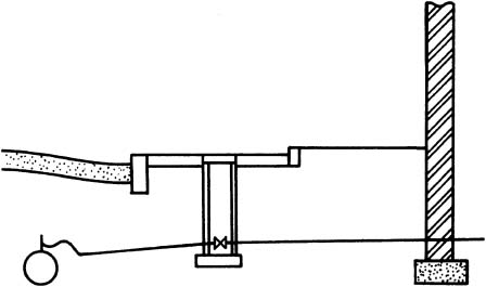
In hard water areas, these problems can be overcome with the installation of a water softener. These devices are relatively compact and will fit conveniently within the housing under a domestic sink. This location is ideal, as the housing will normally accommodate the rising water main and stop valve. It also provides simple access for replacement of salt granules or blocks. The unit contains a resin bed saturated with sodium chloride or common salt. The salt exchanges calcium and magnesium ions for non-scale-forming sodium ions. Regeneration can be by electric timer, but most domestic softeners have an integral water volume metering device.
Typical Installation of a domestic water softener –
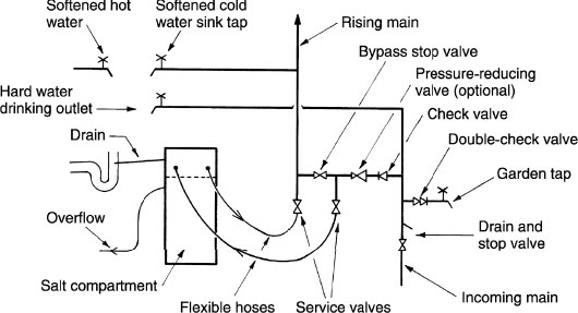
Components of a water softener – resin, sodium chloride (common salt) and a metering device (measures time or volume).
Function – granulated resin is located within a sealed compartment. It is unlikely that this will ever require changing or replenishing during the extensive life of a softener. Resin effectively filters the incoming water by retaining its hardness. Accumulated hardness is automatically washed off with a salt solution and discharged to the drain, leaving the resin recharged with salt. Regeneration is controlled by the metering device and a regulating valve.
Calcium bicarbonate Ca(HCO3)2 becomes sodium bicarbonate Na(HCO3).
Sodium bicarbonate remains soluble in water and unlike calcium, does not deposit as scale when heated.
Maintenance – depending on water consumption, the sodium chloride in the form of salt blocks or granules is replenished by the user. This is the only attention that the unit requires.
Water quality – because of the balanced chemical exchange, over-softening cannot occur. The UK limit for sodium is 200mg per litre of drinking water. The amount of sodium added to water through a water softener is unlikely to exceed this. Nevertheless, a separate hard water drinking outlet is recommended.
Hard water is difficult to lather and the combination of stearates in soap with calcium in water will produce a residual scum on sanitary fitments. Where mains-fed water heaters are to be installed, the supply should be tested. If it has a hardness factor greater than 200ppm or 200mg/l CCE, the water is unsuitable for use with directly fed water heaters. This includes electric showers and combination boilers. In the UK this affects approximately 65% of households.
Inspecting the inside of a kettle will provide an indication as to whether water hardness is an issue. For more reliable assessment a number of simple tests can be applied. As a guide, these include a dip pad test with colour indicator and a colour-change tablet test. Accurate definition in ppm can be achieved by using a handheld TDS (total dissolved solids) meter or by sample analysis in a laboratory.
As indicated on the preceding page, a water softener can be used to remove water hardness and associated limescale deposits. An alternative is a water conditioner and these are available in three different types:
Electronic
Magnetic
Electrolytic
Compared to a water softener, conditioners have the following characteristics:
Scale-forming particles are suspended in water instead of precipitating onto surfaces.
Limescale is not eliminated but controlled.
Generally of relatively low purchase and installation cost when compared with a water softener.
No maintenance, but of limited life.
Water quality unaffected as chemicals are not added.
Domestic Water Conditioner – Electronic
This type of conditioner is attached to the incoming rising main to provide whole-house treatment. It requires no alterations to existing plumbing and no special provision with new installations. The operating and energy requirement is from the electrical mains supply through a standard three-pin power socket. Connected to this is a reduced-voltage (12 volt DC) transformer with a coil of wire or antenna attached to or around the pipe.
Installation –
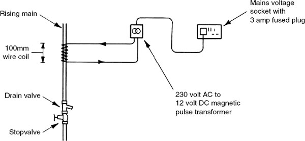
The coil of wire emits a range of electromagnetic signals through the pipe wall and into the water supply. These audio or radio signals have a sonic frequency modulation between 0·5 and 5kHz. The effect is to energise any suspended or diluted material, preventing it from forming as scale on pipe or appliance surfaces. The water remains chemically unchanged, retaining its minerals and taste. Unlike water softener installations, there is no need for a separate drinking water outlet.
Domestic Water Conditioner – Magnetic
A magnetic type of water conditioner is most effective when applied directly as dedicated water treatment to individual water heating appliances such as an electric shower, a combination boiler or an independent water heater. This type of conditioner is unsuitable for whole-house installations where water is stored.
The unit has a very strong magnetic core of ceramic construction. Water supplying a hot water appliance passes around the core and receives a small electrical induction charge. This is sometimes referred to as the magnetohydronamic process. As the water is heated the charged salts or crystals remain suspended in solution, allowing them to be flushed through, thereby preventing their formation as scale deposits on pipe and heating chamber walls.

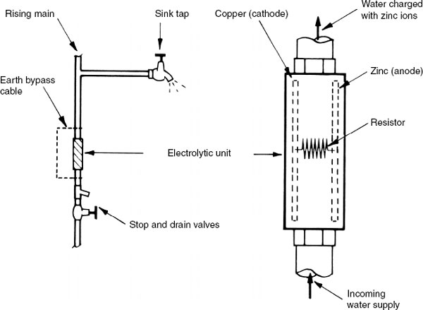
Domestic Water Conditioner – Electrolytic
An electrolytic water conditioner provides whole-house treatment. It is installed on the rising main just after the stopvalve and before the first draw-off. An earth bonding cable should be provided to bypass the unit to ensure earth continuity. No other electrical connection is required.
Within the unit is a galvanic cell consisting of a copper (cathode) and zinc (anode) [see page 132]. Water passing through acts as an electrolyte and gains a small charge. Like the magnetic conditioner, calcium deposits remain in suspension. In addition, zinc ions are produced which attract calcium and magnesium particles to produce suspended crystals of the more plumbing-friendly aragonite. Life expectancy of these units is about 10 years.
Water Treatment – Lime and Soda
The lime and soda process involves relatively large dosing tanks that require regular maintenance and checking. Therefore it is unsuited to individual domestic situations, but it does provide a cost-viable means for reducing the amount of calcium and magnesium in the water supply to industrial and municipal installations.
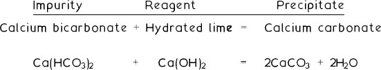
Lime – used as a reagent to remove temporary water hardness by breaking up the soluble bicarbonates into insoluble carbonates:
Soda or soda ash – used as a reagent to remove permanent water hardness by exchanging the carbonate from the sodium (soda ash) with the sulphates, chlorides and nitrates of the calcium impurities.
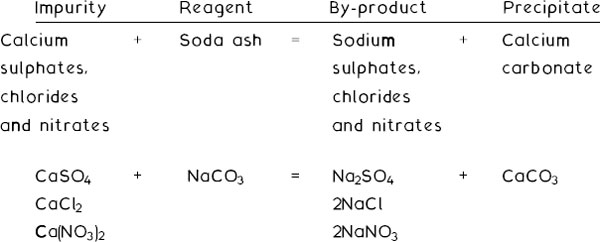
In both processes the precipitate is removed by filtration.
Domestic sanitary appliances – all potable (drinkable) water supplies must be protected against pollution by backflow or back siphonage from water that could be contaminated. Protection is effected by leaving sufficient space or air gap between the lowest point of the control device or tap discharge and the appliance spill-over level.
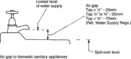
British Standard determination of air gap to domestic sanitary appliances:
Single feed pipe, i.e. one tap, air gap ≥20mm or 2 × internal diameter of tap orifice (take greater value).
Multiple feed pipe, i.e. hot and cold taps, air gap ≥20mm or 2 × sum of orifice diameters (take greater value).
For example, a bath with two taps of 20mm internal diameter inlet orifice:
20mm or 2 × (20 + 20mm) = 80mm. Air gap = 80mm minimum.
Water cisterns or storage vessels pipework supplying potable water must discharge into an unobstructed air gap between the regulating device water inlet to the vessel and the overflow or warning pipe.
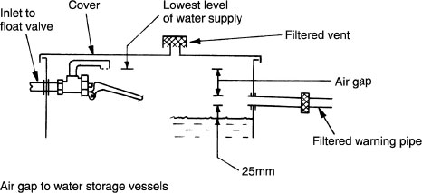
In this situation the air gap should be ≥20mm or 2 × internal diameter of the regulating valve inlet orifice (take greater value).
For example, a 20mm internal diameter orifice:
20mm or 2 × 20mm = 40mm. Air gap = 40mm minimum.
Refs. Water Supply (Water Fittings) Regulations.
BS EN 1717: Protection against pollution of potable water in water installations and general requirements of devices to prevent pollution by backflow.
Secondary backflow or back siphonage protection is an alternative or supplement to the provision of air gaps. It is achieved by using mechanical devices such as double-check valves or a vacuum breaker in the pipeline. Special arrangements of pipework with branches located above the spill level of appliances are also acceptable.
Typical applications – primary heating circuits, washing machines and garden taps.
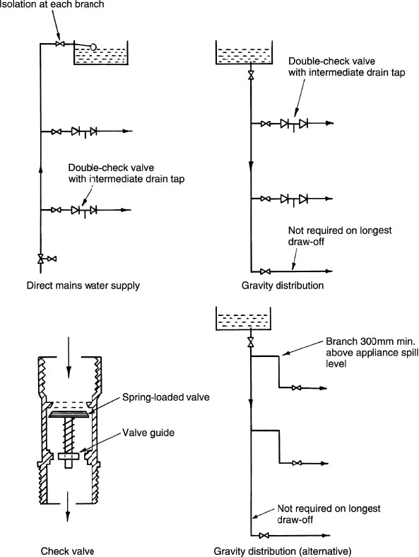
Ref. BS EN 13959: Anti-pollution check valves.
Backflow Prevention – Commercial Applications
Mains water supply to commercial and industrial premises must be protected against the possibility of contamination by backflow. Where toxic processes exist (e.g. dyeing, chemical manufacture, insecticide preparation, car washing, irrigation systems, etc.), it is imperative that the effects of a pressure reduction on drinking water supplies be contained.
Contamination of domestic water supply situations is prevented by installing double-check valves to appliances or systems which could be a risk. In the interests of public health, the water authorities require greater security measures on mains supplies to industrial processes. Hitherto, a device containing two check valves with an intermediate pressure relief valve discharging visibly to a tundish has been considered adequate. Current requirements include a modification to verify or check through test points that the fitting is functioning correctly. This modified device is known as a ‘Verifiable backflow preventer with reduced pressure zone’. It contains three pressure zones separated by differential obturators (two positively loaded check valves). Each pressure zone has a test point to verify that the valve is functioning correctly.

Refs. The Water Supply (Water Fittings) Regulations.
BS EN 1717: Protection against pollution of potable water in water installations and general requirements of devices to prevent pollution by backflow.
Protecting Cold Water Pipes Against Freezing
Cold water installations within a building’s thermal envelope shouldnot need to be insulated. This does not include pipes and cisterns in the roof space unless this area is part of the accommodation. Also excluded from the external envelope is space below suspended ground floors, unheated outhouses and garages.
The purpose of insulating pipes is to retain thermal energy in the pipe and in the water it conveys. Supply pipes are buried at least 750mm below ground for this reason, as well as protection against ground movement.
Common pipe-insulating materials:
Material |
Thermal conductivity (W/mK)λ |
|
|---|---|---|
Rigid phenolic foam |
0.020–0.025 |
|
Polisocyanurate foam |
.. .. |
|
Rigid polyurethane foam |
.. .. |
|
PVC foam |
0.025–0.030 |
|
Expanded polystyrene |
0.030–0.035 |
|
Extruded polystyrene |
.. .. |
|
Cross-linked polyethylene foam |
.. .. |
|
Expanded nitrile rubber |
.. .. |
|
Standard polyethylene foam |
0.035–0.040 |
|
Expanded synthetic rubber |
.. .. |
|
Cellular glass fibre |
.. .. |
|
Note: Thermal conductivity (λ) is a measure of the rate that heat energy is conducted through a material under specific conditions in units of W/mK. The lower the value the better the insulating effect.
Comparative guide to minimum provision of pipe insulation:
Pipe dia. (mm) Thermal conductivity and min. thickness copper

See also WRAS insulation calculator spreadsheet at www.wras.co.uk/insulation.htm based on data from BS 5422: Method for specifying thermal insulation materials for pipes, etc., etc.
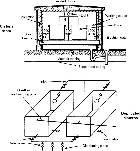
Cisterns can be manufactured from galvanised mild steel (large nondomestic capacities), polypropylene or glass-reinforced plastics. They must be well insulated and supported on adequate bearers to spread the concentrated load. Plastic cisterns will require uniform support on boarding over bearers. A dustproof cover is essential to prevent contamination.
For large buildings, cisterns are accommodated in a purpose-made plant room at roof level or within the roof structure. This room must be well insulated and ventilated, and be provided with thermostatic control of a heating facility.
Where storage demand exceeds 4500 litres, cisterns must be duplicated and interconnected. In the interests of load distribution this should be provided at much lower capacities. For maintenance and repairs each cistern must be capable of isolation and independent operation.

Refs. BS 417–2: Specification for galvanised low carbon steel cisterns, cistern lids, tanks and cylinders.
BS 4213: Cisterns for domestic use. Cold water storage and combined feed and expansion (thermoplastic) cisterns up to 500 litres. Specification.
BS 7181: Specification for storage cisterns up to 500 litres actual capacity for water supply for domestic purposes [see Note 3].
BS EN 13280: Specification for glass fibre-reinforced cisterns of one-piece and sectional construction, for the storage, above ground, of cold water.
Note 1: Where installed in an unheated area such as a roof space, an insulating jacket is to be fitted to the cistern and all associated pipework to be fully insulated.
Note 2: Bearers at 350mm c/c max. for galvanised steel cisterns. Plastic and glass fibre cisterns on sheet plywood over bearers.
Note 3: Actual capacity refers to the quantity of water contained when the float valve and overflow/warning pipe are fitted. Nominal capacity refers to the cistern capacity if filled to the brim.
Water supply pipe/rising main – provided with a servicing valve fitted as close as possible to the float valve to isolate the supply during repair and maintenance.
Inlet valve – water flow control is by a float-operated valve (see page 33) or a motorised valve that responds to the cistern water level. A float valve is the most common and is fitted as high as practicable to maximise storage capacity. An air gap is required between float valve outlet and warning pipe (see page 53) to prevent the possibility of water contamination by backflow. Cistern water level is at least 25mm below the warning pipe overflowing level, effected by adjustment of the ball float.
Outlets – preferably from the cistern base to prevent sediment retention that could contain nutrients for bacteria. Positioned opposite the inlet to encourage cross-flow. This is particularly important with large-capacity cisterns to reduce the possibility of stagnation.
Where hot and cold water feed pipes originate from the same cistern, the hot water connection should be higher than the cold connection in case the float valve seizes allowing the cistern to run dry. Where combined hot and cold water taps and showers are fitted, this will stop hot water flowing before cold water, preventing the possibility of scalding.
Cold feed and distributing outlet pipes are to be provided with a servicing gate valve to prevent water wastage that would otherwise occur from emptying the cistern. An exception is the cold feed from a hot water and/or central heating feed and expansion cistern. In this situation the cold feed to the primary circuit and boiler is not fitted with a valve as this could be inadvertently closed, possibly causing boiling and loss of boiler feed water if the system temperature control were to fail.
Ref. The Water Supply (Water Fittings) Regulations.
Warning pipe – this combines the purpose of providing a conspicuous outfall of water if the float valve malfunctions and safely discharging the surplus water to a suitable place that will not be damaging. A minimum 19mm nominal bore and at least one pipe size above the inlet pipe diameter.
Overflow pipe – for cisterns less than 1000 litres actual capacity, an adequately sized warning pipe is regarded as a suitable overflow. Otherwise, positioned at least 25mm (min. overflowing or invert levels) above the warning pipe with regard to sufficient air gap (see previous page) to discharge potentially damaging and disruptive surplus water to a suitable location. This could be into a rainwater pipe or gutter system with the warning pipe still maintaining a conspicuous discharge.
Cisterns exceeding 5000 litres actual capacity may be fitted with a float switch actuated alarm instead of a warning pipe. This should operate when the cistern water level is within 25mm of the overflow. In this situation the overflow is positioned with its invert level not more than 50mm above normal water level.
Warning and overflow pipes – installed to fall away from the cistern to its point of discharge, preferably to the outside of the building to which it is fitted. For convenience and for visual reasons, discharge may be inside the building over a tundish with an air gap as shown for cisterns on page 53. Alternatively, at least 150mm above a WC rim or other sanitary fitting. A combined bath/overflow manifold may also be used, as shown below:

Cold Water Storage Calculations
Cold water storage data is provided to allow for up to 24-hour interruption of mains water supply.
Building purpose |
Storage/person/24 hrs |
|
|---|---|---|
Boarding-school |
90 litres |
|
Day-school |
30 |
|
Department store with canteen |
45 |
(3) |
Department store without canteen |
40 |
(3) |
Dwellings |
90 |
(1) |
Factory with canteen |
45 |
|
Factory without canteen |
40 |
|
Hostel |
90 |
|
Hotel |
135 |
(2) (3) |
Medical accommodation |
115 |
|
Office with canteen |
45 |
|
Office without canteen |
40 |
|
Public toilets |
15 |
|
Restaurant |
7 per meal |
|
Notes:
(1) 115 or 230 litres min. (see pages 41 and 42).
(2) Variable depending on classification.
(3) Allow for additional storage for public toilets and restaurants.
At the design stage the occupancy of a building may be unknown. Therefore the following may be used as a guide:
Building purpose |
Occupancy |
|---|---|
Department store |
1 person per 30m2 net floor area |
Factory |
30 persons per WC |
Office |
1 person per 10m2 net floor area |
School |
40 persons per classroom |
Shop |
1 person per 10m2 net floor area |
E.g. A 1000m2 (net floor area) office occupied only during the day therefore allow 10 hours’ emergency supply.
![]()
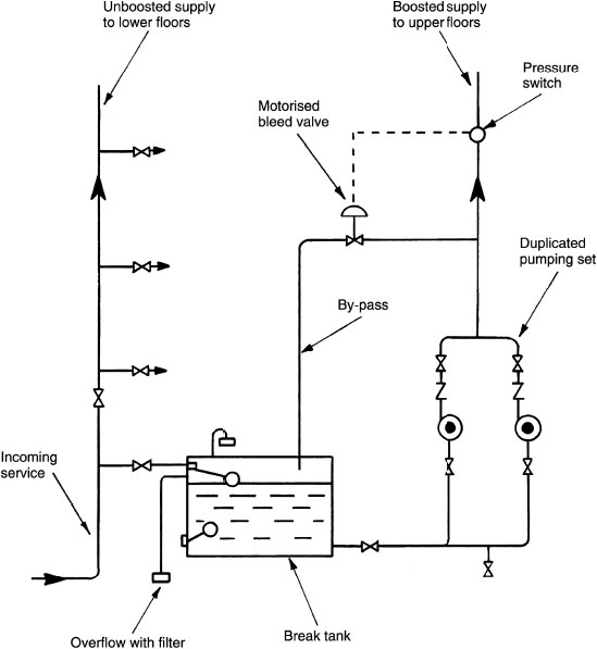
For medium- and high-rise buildings, there is often insufficient mains pressure to supply water directly to the upper floors. Boosting by pump from a break tank is therefore usually necessary and several more of these tanks may be required as the building rises, depending on the pump capacity. A break-pressure cistern is also required on the down service to limit the head or pressure on the lower fittings to a maximum of 30m (approx. 300kPa). The drinking water header pipe or storage vessel supplies drinking water to the upper floors. As this empties and the water reaches a predetermined low level, the pipeline switch engages the duty pump. A float switch in the break tank protects the pumps from dry running if there is an interruption to mains supply. The various pipe sections are fitted with isolating valves to facilitate maintenance and repairs.
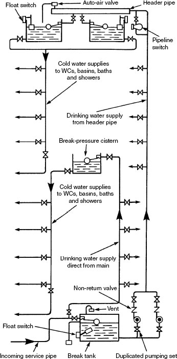
As an alternative to the drinking water header pipe, an autopneumatic cylinder may be used. Compressed air in the cylinder forces water up to the float valves and drinking water outlets on the upper floors. As the cylinder empties a low-pressure switch engages the duty pump. When the pump has replenished the cylinder, a high-pressure switch disengages the pump. In time, some air is absorbed by the water. As this occurs, a float switch detects the high water level in the cylinder and activates an air compressor to regulate the correct volume of air. Break-pressure cisterns may be supplied either from the storage cisterns at roof level or from the rising main. A pressure-reducing valve is sometimes used instead of a break-pressure cistern.

In modest-rise buildings of several storeys where water is in fairly constant demand, water can be boosted from a break tank by a continuously running pump. The installation is much simpler and less costly than the previous two systems as there is less need for specialised items of equipment. Sizing of the pump and its delivery rating are critical, otherwise it could persistently overrun, or at the other extreme be inadequate. Modern pumps have variable settings allowing considerable scope around the design criteria. The pump is normally scheduled to run on a timed programme, e.g. in an office block it may commence an hour before normal occupancy and run on for a couple of hours after. Water delivery should be just enough to meet demand. When demand is low a pressure-regulated motorised bleed valve opens to recirculate water back to the break tank.
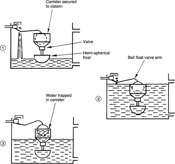
If normal float valves are used to regulate cistern water supply from an auto-pneumatic cylinder (page 63), then cylinder and pump activity will be frequent and uneconomic. Therefore to regulate activity and deliveries to the cistern, a delayed action float valve mechanism is fitted to the storage cistern.
Stage 1. Water filling the cistern lifts hemi – spherical float and closes the canister valve.
Stage 2. Water overflows into the canister and raises the ball float to close off water supply.
Stage 3. As the cistern empties, the ball float remains closed until low water level releases the hemi-spherical float. As this float valve drops, water is released from the canister to open the ball float valve to replenish the cistern from the pneumatic supply.
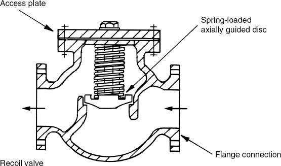
The high-rise cold water supply systems illustrated on pages 62–64 have a non-return valve fitted to the outlet of each booster pump. This essential fitting will prevent reversal of the flow by gravitation when the pump is inactive. Water flow reversal into the break tank would be wasteful, potentially damaging to the plant room and, with a significant head of water, the pressure could burst pump seals, gaskets and other joints.
When the pump stops its delivery, the head of water above it will attempt to reverse and gravitate. A swing pattern non-return valve of the type shown on page 164 will not function instantly and a small amount of backflowing water will allow the water column to drop. As the disc closes, the column will be halted abruptly and this may produce vibrations or water hammer through the installation.
A rapid functioning spring-assisted type of non-return valve is preferred particularly where the potential head will exceed 50m. This type of non-return valve is similar in principle to the horizontal lift pattern shown on page 164 but is produced to suit larger diameter pipes. In this format it usually has flanged connections and is known as a recoil valve.
Pump power calculations are based on the physics of work done relative to time. Work done is applied force through distance moved. Unit of measurement is the Joule, the work done when a 1 Newton force acts through 1 metre distance, i.e. 1 Joule = 1N × 1m.
Time is expressed in seconds. By combining work done over a period of time:

Force in Newtons = kg mass × acceleration due to gravity [9·81m/s2 (Power expressed in Watts = ( mass × 9·81 × distance) ÷ time For example

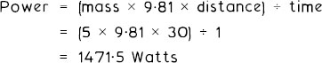
Allowing for the pump efficiency: 1471·5 × (100 ÷ 75) = 1962 Watts Pump rating: 2kW at 5l/s (1962 Watts rounded up to nearest kW)
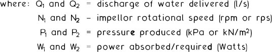
In normal application with the exception of maintenance and repair, the components of a water pump will remain unchanged during use. If a pump proves unsuitable for purpose, the complete unit is usually replaced with a pump of better specification. A pump with an impellor of constant diameter will have the following characteristics:
Water quantity (Q) or volume delivered varies directly with the rotational speed (N) or angular velocity (rpm) of the impellor.

Pressure (P) produced varies as the square of rotational speed (N).

Power (W) required varies as the cube of rotational speed (N).

E.g. A 2kW pump discharges 5kg/s when the pump impellor speed is 1000rpm. Increasing the impellor speed to 1200rpm will provide the following characteristics:
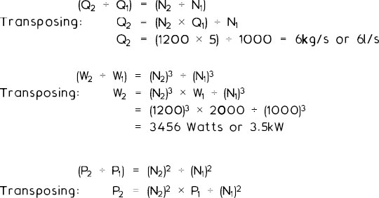
At 40kPa pressure at 1000 rpm increasing to 1200rpm will produce:
![]()
If a water pump has adaptability to component change and the impellor can be replaced with compatible units of different diameters, the following apply:
At constant rotational speed (N) the water quantity (Q) delivered varies as the cube of the impellor diameter (D).

Pressure (P) produced varies as the square of impellor diameter (D).

Power (W) required varies as the fifth power of impellor diameter (D).

Single two-speed pump characteristics:
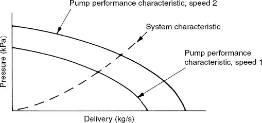
Duplicate pumps of equal characteristics working together in parallel:

Delivery is theoretically twice that of a single pump, but realistically the pressure or resistance to flow in the system will determine the flow, i.e. flow at B is not twice that at A.
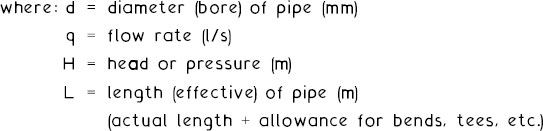
Thomas Box formula:
![]()
e.g
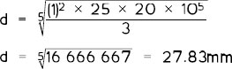
The nearest commercial size above this is 32mm bore steel or 35mm outside diameter copper.
Note: Head in metres can be converted to pressure in kPa by multiplying by gravity, e.g. 3m × 9·81 = 29·43kPa (approx. 30kPa).

Approximate equivalent pipe lengths of some fittings (m).

Notes: Figure given for a tee is the change of direction; straight through has no significant effect. These figures are only intended as a guide; they will vary between materials and design of fittings.
Recommended flow rates for various sanitary appliances (litres/sec) |
|
|---|---|
WC cistern |
0·11 |
Hand basin |
0·15 |
Hand basin (spray tap) |
0·03 |
Bath (19mm tap) |
0·30 |
Bath (25mm tap) |
0·60 |
Shower |
0·11 |
Sink (13mm tap) |
0·19 |
Sink (19mm tap) |
0·30 |
Sink (25mm tap) |
0·40 |
Pipe Sizing – Loading Units (BS 6700)
Loading units are factors which can be applied to a variety of appliances. They have been established by considering the frequency of use of individual appliances and the desired water flow rate.
Appliance |
Loading units |
|---|---|
Hand basin |
1·5 to 3 (depends on application) |
WC cistern |
2 |
Washing machine |
3 |
Dishwasher |
3 |
Shower |
3 |
Sink (13mm tap) |
3 |
Sink (19mm tap) |
5 |
Bath (19mm tap) |
10 |
Bath (25mm tap) |
22 |
By determining the number of appliances on a pipework system and summating the loading units, an equivalent flow in litres per second can be established from the following conversion graph:

Pipe Sizing – Head Loss and Flow Rate Nomogram
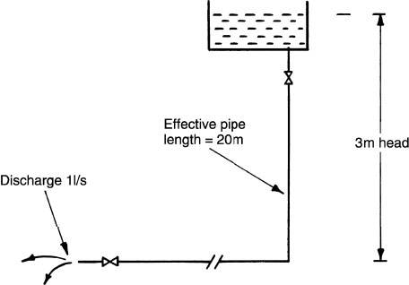
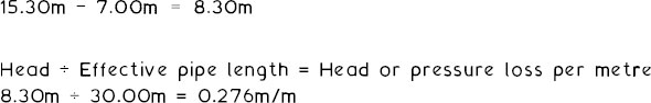
Pressure or head loss in pipework systems can be expressed as the relationship between available pressure (kPa) or head (m) and the effective length (m) of pipework. The formula calculation on page 70 can serve as an example:
Head = 3m. Effective pipe length = 20m. So, 3/20 = 0.15m/m
By establishing the flow rate from loading units or predetermined criteria (1l/s in our example), a nomogram may be used to obtain the pipe diameter. The chart below is for illustration and general use. For greater accuracy, pipe manufacturers’ design data should be consulted for different materials and variations in water temperatures.

Ref. BS 6700: Design, installation, testing and maintenance of services supplying water for domestic use within buildings and their curtilage. Specification.
Pipe Sizing – Head Loss and Flow Rate Application
On the preceding page a pipe sizing chart or nomogram is used to verify the size of pipe calculated by formula on page 70. The nomogram may also be used to determine the size of water mains and supply pipes as shown in the following example:

Pressure or residual head at the cistern will be the minimum mains pressure less the height the water has to rise to the cistern. To convert 150kPa to metres head, divide by gravity (9.81), i.e.:
![]()
Pressure or residual head at the cistern inlet is therefore:
Extending a straight line through the nomogram coordinates of 0.176m/m and the selected cistern filling rate of 0.2l/s indicates that a copper pipe of at least 15mm outside diameter or equivalent is adequate.
Hydraulics is the experimental science concerning the study of energy in fluid flow. That is, the force of pressure required to overcome the resistance to fluid flowing through pipes, caused by the friction between the pipe and liquid movement.
The total energy of the liquid flowing in a pipe declines as the pipe length increases, due mainly to friction between the fluid and the pipe wall. The amount of energy or pressure loss will depend on:
Smoothness/roughness of the internal pipe wall.
Diameter of pipe or circumference of internal pipe wall.
Length of pipe.
Velocity of fluid flow.
Amount of turbulence in the flow.
Viscosity and temperature of fluid.
Theories relating to pressure loss by fluids flowing in pipes are diverse, but an established relationship is that the pressure losses (h) caused by friction are proportional to the square of the velocity of flow (v):
![]()
From this, for a pipe of constant size it may be seen that by developing the proportional relationship, a doubling (or more) of pressure will increase the velocity accordingly:
h (m) |
v (m/s) |
|---|---|
4 |
1·5 |
8 |
2·12 (1·5 × √2) |
12 |
2·60 (1·5 × √3) |
16 |
3·00 (1·5 × √4) or (2·12 × √2) |
24 |
3·66 (1·5 × √6) or (2·60 × √2) |
32 |
4·24 (1·5 × √8) or (3·00 × √2) etc., etc. |
It can also be shown that if the condition (temperature and viscosity) of a fluid in a pipe remains constant, the discharge through that pipe is directly proportional to the square root of the fifth power of its diameter:
![]()
This relationship can be identified in the Thomas Box pipe sizing formula shown on page 70.
Bernoulli’s theorem (see also pages 269 and 270) – the theoretical basis for fluid flow, established with the assumption that there is no fluid flow energy loss due to friction. It therefore applies to the steady motion where a fluid moves in streamlines as depicted in the diagram below. Theoretically, the fixed path of fluid movement passes through given points of known small cross-sectional area (a1, a2), pressure (h1, h2) and velocity (v1, v2).

The total energy of unit weight of a fluid in flow can be expressed by the following summation:
Potential energy (z) + Pressure energy (h) + Kinetic energy (v2/2g) = Constant, i.e.: If there is a loss of energy in any category there must be gain in the others for the balance to remain constant.
By formula –
![]()
Note: g represents gravitational acceleration of 9.81m/s2
Bernoulli’s theory is approximately true for liquid movement in a short length of straight pipe, but with pipework installations the pressure head decreases over distance due to frictional resistance between the fluid conveyed and the pipe wall. Nevertheless, Bernoulli’s principles of pressure differentials have become an established basis for the development of numerous other liquid flow calculations.
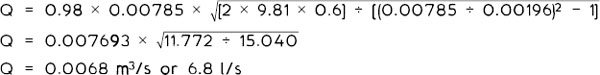
Venturimeter – a device developed from Bernoulli’s principles of fluid flow for measuring the quantity or discharge of a liquid through a pipe (typically a water main), by comparing pressure differences through a constriction in the pipe. In the direction of flow, the instrument combines a fairly rapidly tapering pipe to reduce the cross-sectional area at the throat. Thereafter, is a relatively long taper to enlarge the cross-section back to the original diameter of the pipe.

The discharge formula may be expressed as:
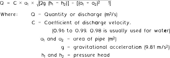
E.g. a 100mm diameter pipe (area, a1 = 0·00785m2) and an instrument throat diameter of 50mm (area, a2 = 0·00196m2).
h1 − h2 = 600mm (0·6m). C = 0·98.
Reynolds number – a coefficient of friction based on the criteria for similarity of motion for all fluids. Relevant factors are related by formula:
![]()
This is more conveniently expressed as ![]()
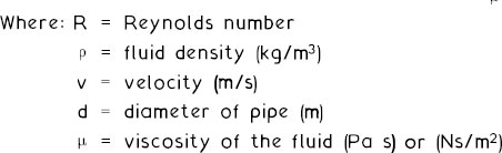
Whatever the fluid type or temperature, an R value of less than 2000 is considered streamline or laminar. A value greater than 2000 indicates that the fluid movement is turbulent.
E.g. 1. A 12mm diameter pipe conveying fluid of density 1000kg/m3 and viscosity of 0.013Pa s at 2m/s flow velocity has a Reynolds number of:
![]()
D’Arcy formula – used for calculating the pressure head loss of a fluid flowing full bore in a pipe, due to friction between fluid and pipe surface.
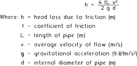
Note: ‘f’, the D’Arcy coefficient, ranges from about 0.005 (smooth pipe surfaces and streamline flow) to 0.010 (rough pipe surfaces and turbulent flow). Tables may be consulted, although a mid-value of 0.0075 is appropriate for most problem solving.
E.g. 2. A 12mm diameter pipe, 10m long, conveying a fluid at a velocity flow of 2m/s:
![]()
Depending on the data available, it is possible to transpose the D’Arcy formula for other purposes. For example, it may be used to calculate pipe diameter in this format:
![]()
Flow rate (Q) – the discharge rate or flow rate of a fluid in a pipe is expressed as the volume in cubic metres (V) flowing per second (s). Q (m3/s) is dependent on the pipe cross-sectional area dimensions (m2) and the velocity of fluid flow (m/s). Q may also be expressed in litres per second, where 1m3/s = 1 000l/s.
A liquid flowing at an average velocity (v) in a pipe of constant area (A) discharging a length (L) of liquid every second (s) has the following relationship:
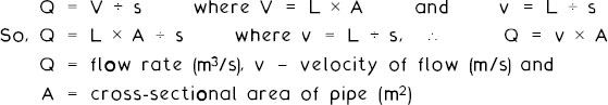
E.g. 1. The quantity of water flowing through a 12mm diameter pipe at 2m/s will be:
![]()
Relative discharge of pipes – this formula may be used to estimate the number of smaller branch pipes that can be successfully supplied by one main pipe:
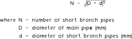
E.g. 2. The number of 32mm short branch pipes that can be served from one 150mm main will be:
![]()
E.g. 3. The size of water main required to supply 15 20mm short branch pipes will be by formula transposition:
![]()