

Networking
This chapter provides preferred practices for IBM Scale Out Network Attached Storage (SONAS) network configuration:
3.1 Terminology
Many terms are used by networking architects and specialists to describe networking. Linux and networking switch manufacturers often use different terms for the same concepts. The next sections list some SONAS-related networking terms and explain bonding modes.
3.1.1 Networking terms
This section provides terms and abbreviations that are common and relevant to network configurations in general. The purpose is to make you familiar with the terms and abbreviations that are used throughout this chapter:
Address Resolution Protocol (ARP)
ARP is a protocol that is used for resolution of network layer addresses (example Internet Protocol (IP) addresses) into link layer addresses (message authentication code (MAC) addresses). It is also the name of the program for manipulating these addresses in most operating systems.
Bonding A method for grouping several physical network ports into a single virtual adapter for one or more of the following reasons: Load sharing, throughput enhancement, redundancy, and high availability (HA). The term link aggregation is typically used for the same concept on network equipment.
Default route A routing table entry that is used to direct frames for which a next hop is not explicitly listed in the table.
Hop/hop count A hop in routed networks is the passage of a network packet through a router (or similar) on the way to its destination. Hop count refers to the number of hops of routers that a packet must pass through on its way to its destination, and is an estimate of distance in a network.
Jumbo frames Jumbo frames are Ethernet frames with more than 1500 bytes of payload. Conventionally, jumbo frames can carry up to 9000 bytes of payload as the maximum transmission unit (MTU), but variations exist and care must be taken when you are using the term.
Many Gigabit Ethernet (GbE) switches and Gigabit Ethernet network interface cards (NICs) support jumbo frames. Ethernet jumbo frames improve performance in some environments by enabling by moving more data with less required resources.
Management network
The SONAS network carries the configuration, health monitoring, and other low-bandwidth messaging among the nodes. Both management-network Ethernet adapters in each node are bonded to share a single IP address.
Netgroup A network-wide group of hosts and users. A netgroup can be used to restrict access to shared information on Network File Systems (NFS). SONAS supports netgroups only for grouping hosts to restrict access to NFS.
Network address translation (NAT)
NAT is a technique that is typically used with network routers. The benefit of the NAT gateway within SONAS is that it provides an internal network failover path by which local SONAS functions on a given management node or interface node can still access public services such as domain name server (DNS) and Lightweight Directory Access Protocol (LDAP).
Ping and round trip time (RTT)
Ping is a network diagnostic tool that sends an Internet Control Message Protocol (ICMP) Echo Request to a distant node. The remote node must immediately return an ICMP Echo Reply packet back to the originating node. The RTT reflects time between the transmission of a packet and the receipt of its acknowledgment, and can be used to determine the latency between two systems.
Virtual local area network (VLAN)
VLAN is a software-defined LAN that groups network elements in the same broadcast domain.
xmit_hash_policy With certain bonding protocols, when transmitting using multiple interfaces, a policy or algorithm must exist to determine which interface to use to attempt balance the network load.
3.1.2 Bonding modes
SONAS supports the following bonding modes. The simple numbers 0 - 6 are how Linux and SONAS refer to the bonding modes in the configuration file. Network equipment manufacturers and network support personnel generally use the term that is listed in parenthesis:
0 (balance-rr) Transmits packets in a sequential order from the first available subordinate through the last. Suppose that two real interfaces are subordinates in the bond, and two packets arrive destined out of the bonded interface.
The first is transmitted on the first subordinate and the second frame is transmitted on the second subordinate. The third packet is sent on the first, and so on. This technique provides load balancing and fault tolerance.
|
Note: Mode 0 is not recommended for general NAS protocols that heavily use Transmission Control Protocol/Internet Protocol (TCP/IP) versus User Datagram Protocol (UDP) because it can trigger congestion control actions (retransmission due to out of order packets) resulting in loss of intended performance gains. Generally bonding mode 2 or mode 4 are preferred over this mode when link aggregation performance and high availability are needed.
|
1 (active-backup) An active backup configuration. Only one subordinate in the bond configuration is active at a time. Other subordinates become inactive until the active, primary subordinate fails. To avoid switch confusion, the MAC address is externally visible only on one port.
This mode provides fault tolerance. Currently, 10 Gigabit converged network adapters (CNAs) in Interface nodes for external data connectivity are configured to handle IP over InfiniBand in this mode.
Moreover, all internal management NICs and internal data InfiniBand host channel adapters (HCAs) are configured in SONAS by default in this active backup configuration. Therefore, all internal SONAS networks share a single IP address, and work in hot standby configuration.
2 (balance-xor) Transmits based on an exclusive or (XOR) formula. The Source MAC address is XOR’d with destination MAC address Modulo subordinate count. It selects the same subordinate for each destination MAC address, and provides load balancing and fault tolerance.
4 (802.3ad) Also known as dynamic link aggregation based on the Link Aggregation Control Protocol (LACP). It creates aggregation groups that share speed and duplex settings. This mode requires a switch that supports Institute of Electrical and Electronics Engineers (IEEE) 802.3ad.
|
Mode 4: IEEE 802.3ad Dynamic link aggregation:
•Create aggregation groups that share speed and duplex settings.
•Here are the requirements for creating an 802.3ad link aggregate (bond):
– All physical ports in the aggregate must have the same duplex setting and speed.
– All physical ports in the aggregate must connect to the same Ethernet switch.
– The Ethernet switch to which all ports in the aggregate connect must support 802.3ad LACP.
|
5 (balance-tlb) Adaptive transmit load balancing. The outgoing traffic is distributed according to the current load and queue on each subordinate interface. Incoming traffic is received by the current subordinate. Does not require any special switch support.
6 (balance-alb) Adaptive load balancing. The outgoing traffic is redistributed between all subordinates that are working in bond configuration according to the current load on each subordinate. The receive load balancing is achieved through ARP negotiation.
The receive load is redistributed by using a round robin algorithm among the group of subordinates in the bond. Effectively, this configuration combines bandwidth into a single connection, so it provides fault tolerance and load balancing. Adaptive low balancing does not require any special switch support.
3.2 SONAS networking
The SONAS hardware has several physical network ports for client communication, and for management tasks. The number of ports varies based on the SONAS configuration. Ports are used for management, backup, replication, and for data transfer from the clients. Each physical port is assigned to a bond. The default bonding mode of SONAS is mode 1 or active/backup. However, this setup can be changed in specific cases as needed to fulfill the wanted behavior in terms of performance and redundancy.
3.2.1 Interface node networking
Public interfaces are bonded redundantly into network groups of interface nodes that work together to share the load. Bonds for each node within a network group must have identical interface names (ethX0, ethX1, and so on). This configuration is required for proper node failover, where network IP addresses and supporting interfaces are moved from node to node within the network group due to a failover event. For example, if a network group is attached to ethX0, all nodes within that network group must support the ethX0 bond interface for managing the IP addresses that are assigned to the shared network.
When creating network groups, configuring uniform node characteristics for all nodes within a network group maximizes node behavior consistency on node failover. If node interfaces are not configured consistently within a network group, traffic routing becomes unpredictable. This can occur when a mixture of 1 GbE and 10 GbE speeds exist on assigned nodes within a network group.
If a node with only 1 GbE of network bandwidth capability for an interface assumes responsibility during failover from a node that had a 10 GbE network speed for the identical interface, reduced client performance and unwanted behavior can occur as 10 GbE incoming traffic is replied to out of 1 GbE port channels. Other node characteristic consistencies that maximize node failover behavior include bonding mode, MTU size, virtual local area network (VLAN) assignment, and xmit_hash_policy.
3.2.2 Understanding your network topology
Scale out NAS solutions are designed to simplify data access for a large contingency of your business, be it analytical or scientific computing, or simple home directories. A scale out solution by nature suggests that you plan to grow.
NAS is not a simplified block solution with isolated paths from application to storage or limited protocol and congestion to consider. NAS solutions are end-to-end network intensive protocol rich environments with many communication points of consideration in the path between the client demand and the service delivery.
Under-estimating the importance of the enterprise solution networked component interaction, bandwidth, latencies, and redundancy causes problems for the long-term strategy. It is important to pay close attention to these aspects regularly and in all troubleshooting events:
•First, consider flattening the network (mapping everything important and taking out the complexity).
•For any SONAS solution, ensure that an up-to-date network topology diagram is available to SONAS administration staff.
•Network switches should be well-managed and kept up to date. Network and client communication devices and firmware should be compatible with current switch manufacturer recommendations.
•Ensure that RTT distance and network hops between SONAS and client and authentication servers, antivirus servers, DNS, Network Time Protocol (NTP), backup and Hierarchical Storage Manager (HSM) primaries and secondaries, is understood at installation time. These should be regularly checked and validated. In some cases, high RTT times to such things as authentication servers can cause extraordinary latencies in client service response times.
•In some cases, it might be advantageous to build new service secondaries closer to your SONAS clusters (from a network perspective) to improve response and overall performance.
•Measure and record your RTT times to all your key solutions and key clients in different network segments of your environment. Ping can be a simple tool for testing and capturing those key points in your environment.
•When a disaster recovery (DR) site is assembled, it is equally important to ensure that RTT times to secondary servers are also quick to ensure the expectation of equal service response if there is a disaster. This is often overlooked in a complete solution, and never appreciated until disaster strikes (when it might be too late to fix the network quickly).
•Establish a troubleshooting protocol with your network team (in advance) to understand how to quickly collect, capture, record, share, and evaluate network diagnostic information if there is a service complaint. By establishing this protocol early in your deployment, you simplify time to resolution and greatly decrease administrative volley and service-related anxiety.
3.3 Network bonding overview
This section provides an overview of network bonding. It describes configuring the network for maximum throughput and availability, and when maximum throughput and availability can be obtained.
3.3.1 Link Aggregation Control Protocol
The preferred practice for networking for performance and reliability is to bond 2 or 4 ports by using Mode 4 (LACP or 802.3ad) bonds with the xmit_hash_policy policy set to Layer3+4. The switch ports to which the bond is connected to should be grouped into an 802.3ad compatible channel group. This grouping might be referred to as dynamic link aggregation or LACP, which is the control protocol that is used by 802.3ad in switch configuration options.
The precise method for these configurations varies by switch manufacturer and model. A balance algorithm should also be chosen for outgoing traffic on both the bond and the switch. The algorithms that are available on the switch and the method to select them vary by switch.
|
Static versus dynamic: Static link aggregation is the generic term that was originally referred to by Cisco as Etherchannel. As the name implies, static link aggregation is different from 802.3ad dynamic link aggregation.
|
3.3.2 Transmission policies
When network interfaces are bonded together, the switch and the server need to have algorithms to balance the load across the adapters. The balancing algorithm options are described in the xmit_hash_policy option of the bonding kernel documentation. The xmit_hash_policy option selects the transmit hash policy to use for output interface selection in balance-xor and 802.3ad modes. The default value of the xmit_hash_policy option is layer2. The other two option values are layer2+3 and layer3+4.
For LACP bonding, the preferred practice is to use xmit_hash_policy with layer3+4 option.
|
Important: The description of layer3+4 in the kernel documentation contains the following note: This algorithm is not fully 802.3ad compliant. A single TCP or UDP conversation that contains both fragmented and unfragmented packets sees packets striped across two interfaces. This configuration might result in out-of-order delivery. Most traffic types do not meet this criteria, as TCP rarely fragments traffic, and most UDP traffic is not involved in extended conversations. Other implementations of 802.3ad might or might not tolerate this noncompliance.
|
The layer3+4 note about 802.3ad noncompliance has not been a problem in practice. Strongly consider using the layer3+4 value for ports that use bonding modes 2 and 4, because it provides the best distribution of traffic for most use cases. The layer2+3 value is preferred only if there is a significant amount of fragmented IP traffic, such as with NFS over UDP as one example, and the dispersion of fragments causes performance degradation or reassembly failures, or the out-of-order delivery causes 802.3ad noncompliance or other issues.
3.3.3 Jumbo Frames
For improved performance, set up jumbo frames.
|
Jumbo frames: SONAS supports jumbo frames. However, use jumbo frames only if the end-to-end infrastructure can also support it. Setting jumbo frames without end-to-end support might lead to network instability and inconsistent performance.
|
If you do not specify the proper MTU setting on your network infrastructure, you will produce performance irregularity. Those problems present themselves in the following scenario:
•A client transmits a 9000-byte payload frame. The frame size that is transmitted to your network in a non-VLAN trunked transmission is 9018 bytes.
•If your network is not configured to accept a 9018-byte frame, it discards the transmission.
•If MTU discovery is enabled, the systems negotiate the payload size of each future frame transmission to a smaller value.
•If MTU discovery is not possible, the transmission fails.
•The process of negotiating a smaller payload increases latency and system processor use as the system is forced to continually negotiate smaller payload sizes.
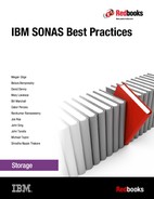
Figure 3-1 illustrates the configuration requirements for a network infrastructure that has enabled jumbo frames for the clients on Bond1. The clients on Bond0 are using a smaller MTU. The routing on the SONAS server must be configured correctly, and the clients on the network must be segregated by MTU size.
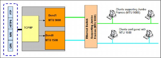
Figure 3-1 Jumbo frames configuration example
.
|
Remember: All VLAN networks that are created and attached on a jumbo frame MTU bond interface inherit the MTU size of the base bond. If you have a base bond, for example ethX0, a VLAN that you attach on that interface inherits the jumbo frame MTU setting. This setting requires VLANs to have the same MTU sizes as their parent bond interface. You cannot define separate VLAN MTU sizes.
Important: SONAS supports only MTU 1500 and MTU 9000 for 10 Gbit cards.
|
3.3.4 Configuring a system for high availability and throughput
Depending on your network switches, SONAS systems can be configured for high availability or throughput. Ideally both can be obtained together.
By default, the mknwbond command uses mode 1 (active-backup). This setting delivers high availability, but no increase in throughput. If your network switch supports LACP, use bonding mode 4. Otherwise, use mode 6.
The following sections describe bonding in more detail. The examples are similar for 1 GbE and 10 GbE, so in most cases the speed of the adapters is not described.
Single and multi-switch topology that uses bond mode 4
The 802.3ad mode requires that the switch have the appropriate ports configured as an 802.3ad aggregation. The precise method that is used to configure this setting varies from switch to switch, but, for example, a Cisco 3550 series switch requires that the appropriate ports first be grouped in a single Etherchannel instance, then that Etherchannel is set to mode LACP to enable 802.3ad (rather than standard Etherchannel).
In this example, these two ports are grouped to one single bond. In a single-switch topology, both ports are connected to the same switch, as shown in Figure 3-2. The switch ports to which the bond is connected to should be grouped into an 802.3ad compatible channel group.
Figure 3-2 Single-switch layout example
Bond mode 6 (balance-tlb) with two ports that are connected to a single switch also looks like Figure 3-2.
Figure 3-3 shows a configuration with four network ports in a system that are all bonded together and attached to a single switch. This configuration does not make sense unless your network switch supports a bonding mode where you can have multiple ports active at the same time.

Figure 3-3 Example single-switch configuration layout
Multi-switch topology
Figure 3-4 shows two ports that are grouped to one single bond. In a multi-switch topology, ports are connected to different switches. The network switches need to be configured to support this configuration.

Figure 3-4 Multi-switch layout example
|
High availability considerations: When client I/O paths are moved from one SONAS node to another SONAS node, the failover operation issues gratuitous ARPs to inform the network of the MAC address changes for the IP addresses that the client is using on the SONAS interface nodes. Gratuitous ARPs to the network generally reach all of the equipment that directs the client traffic to the SONAS interface node. If this does not occur, you might consider changing timeout values for the ARP caches to values that are more appropriate for the particular network’s traffic and the delay latency that SONAS I/O clients can accept. A timeout value of 5 to 10 minutes can accommodate most SONAS node failover operations.
|
Figure 3-5 shows an example multi-switch topology layout with four ports on the server.

Figure 3-5 Example multi-switch topology layout
Mode 4 bonding example with two ports
The following section shows the commands that are used to create a mode 4 bond with the layer3+4 transmission hash.
Configuration requirements
The following prerequisites must be fulfilled:
•No network is assigned to the subordinates.
•No IP address is active on any of the subordinates.
Configuration Steps
Complete the following steps to create a multi-switch layout:
1. Detach the network from the interface and check the configuration. The commands are shown in Example 3-1.
Example 3-1 Detach the network from the interface and check the configuration
$ detachnw ethX0 10.0.0.0/24 -g int
Removing network NAT gateway...
EFSSG0087I NAT gateway successfully removed.
EFSSG0015I Refreshing data..
$lsnwinterface
Node Interface MAC Master/Subordinate Bonding mode Transmit hash policy Up/Down Speed IP-Addresses MTU
int001st001 ethX0 02:1c:d1:02:03:00 MASTER active-backup (1) UP 10000 1500
mgmt001st001 ethX0 02:1c:d1:00:03:00 MASTER active-backup (1) UP 10000 1500
mgmt002st001 ethX0 02:1c:d1:01:03:00 MASTER active-backup (1) UP 10000 1500
2. Remove the existing bonds on all the servers, as shown in Example 3-2.
Example 3-2 removing existing bonds
$ rmnwbond int001st001 ethX0
EFSSG1000I The command completed successfully.
$ rmnwbond mgmt001st001 ethX0
EFSSG1000I The command completed successfully.
$ rmnwbond mgmt002st001ethX0
EFSSG1000I The command completed successfully.
|
Note: The output in this section is abbreviated for clarity. Also note that typically, when bonded, the MAC address of all the subordinates and the bond is the same.
|
Example 3-3 Output of the lswinterface command
$ lsnwinterface -x
Node Interface MAC Master/Subordinate Bonding mode Transmit hash policy Up/Down Speed IP-Addresses MTU
int001st001 eth0 02:1c:d1:02:03:01 UP 10000 1500
int001st001 eth1 02:1c:d1:02:03:02 UP 10000 1500
mgmt001st001 eth0 02:1c:d1:00:03:01 UP 10000 1500
mgmt001st001 ethl 02:1c:d1:00:03:02 UP 10000 1500
mgmt002st001 eth0 02:1c:d1:01:03:01 UP 10000 1500
mgmt002st001 eth1 02:1c:d1:01:03:02 UP 10000 1500
4. Create new bonds on all nodes by using the mknwbond command with the mode parameter, as shown in Example 3-4. Note the usage of bond mode 4 and the layer3+4 transmission hash. Both management and data traffic can be used on this bond.
You can use the mknwbond command-line interface (CLI) command to create a bond interface by specifying the subordinate network interfaces on a specified node that are grouped to act as one logical network interface.
Example 3-4 Creating new bond interfaces
$ mknwbond int001st001 eth0,eth1 --mode 4 --mtu 9000 -xmit layer3+4
EFSSG0577W Warning: creating a bond with mode 802.3ad (4) might require additional switch configuration work to access the network.
EFSSG0089I Network bond ethX0 successfully created.
$ mknwbond mgmt001st001 eth0,eth1 --mode 4 --mtu 9000 -xmit layer3+4
EFSSG0577W Warning: creating a bond with mode 802.3ad (4) might require additional switch configuration work to access the network.
EFSSG0089I Network bond ethX0 successfully created.
$ mknwbond mgmt002st001 eth0,eth1 --mode 4 --mtu 9000 -xmit layer3+4
EFSSG0577W Warning: creating a bond with mode 802.3ad (4) might require additional switch configuration work to access the network.
EFSSG0089I Network bond ethX0 successfully created.
5. Check the network and bonding configuration, as shown in Example 3-5.
Example 3-5 Check the network and bonding configuration
$ lsnwinterface -x
Node Interface MAC Master/Subordinate Bonding mode Transmit hash policy Up/Down Speed IP-Addresses MTU
int001st001 ethX0 02:1c:d1:02:03:00 MASTER 802.3ad (4) layer3+4 UP 20000 9000
int001st001 ethXsl0_0 02:1c:d1:02:03:01 SUBORDINATE UP 10000 9000
int001st001 ethXsl0_1 02:1c:d1:02:03:02 SUBORDINATE UP 10000 9000
mgmt001st001 ethX0 02:1c:d1:00:03:00 MASTER 802.3ad (4) layer3+4 UP 20000 9000
mgmt001st001 ethXsl0_0 02:1c:d1:00:03:01 SUBORDINATE UP 10000 9000
mgmt001st001 ethXsl0_1 02:1c:d1:00:03:02 SUBORDINATE UP 10000 9000
mgmt002st001 ethX0 02:1c:d1:01:03:00 MASTER 802.3ad (4) layer3+4 UP 20000 9000
mgmt002st001 ethXsl0_0 02:1c:d1:01:03:01 SUBORDINATE UP 10000 9000
mgmt002st001 ethXsl0_1 02:1c:d1:01:03:02 SUBORDINATE UP 10000 9000
6. Attach the network or networks to the interface, as shown in Example 3-6.
Example 3-6 Attach the network or networks to the interface
$ attachnw 10.0.0.0/24 ethX0 -g int
EFSSG0015I Refreshing data.
3.3.5 Bonding examples
In this section, several examples are shown that use CLI commands to creates bonds and display the configurations.
Mode 6 bonding example with four ports
In the following example, all interface nodes and interface/management nodes have one 4-port 1 GbE Ethernet adapter installed. One bond with all four ports using active/active settings is created. On all nodes, eth0, eth1, eth2, and eth3 adapters are bonded to one single bond.
Configuration requirements
The following prerequisites must be fulfilled:
•No network is assigned to the subordinates.
•No IP address is active on any of the subordinates.
Configuration steps
Complete the following configuration steps:
1. Detach the network. The commands to detach the network from the interface and check the configuration are the same, as shown previously in Example 3-1 on page 80.
2. Remove the existing bonds on all the servers, as shown in Example 3-2 on page 81.
3. Create the new bond on all nodes using the mknwbond command with the mode parameter (Example 3-7).
Example 3-7 Configuring network bonding by using the CLI
$ mknwbond int001st001 eth0,eth1,eth2,eth3 --mode 6
EFSSG0089I Network bond ethX0 successfully created.
$ mknwbond mgmt001st001 eth0,eth1,eth2,eth3 --mode 6
EFSSG0089I Network bond ethX0 successfully created.
$ mknwbond mgmt002st001 eth0,eth1,eth2,eth3 --mode 6
EFSSG0089I Network bond ethX0 successfully created.
Example 3-8 Using the lswinterface command to check the settings
$ lsnwinterface -x
Node Interface MAC Master/Subordinate Bonding mode Transmit hash policy Up/Down Speed IP-Addresses MTU
int001st001 ethX0 02:1c:d1:02:03:00 MASTER balance-alb (6) UP 1000 1500
int001st001 ethXsl0_0 02:1c:d1:02:03:01 SUBORDINATE UP 1000 1500
int001st001 ethXsl0_1 02:1c:d1:02:03:02 SUBORDINATE UP 1000 1500
int001st001 ethXsl0_2 02:1c:d1:02:03:03 SUBORDINATE UP 1000 1500
int001st001 ethXsl0_3 02:1c:d1:02:03:04 SUBORDINATE UP 1000 1500
mgmt001st001 ethX0 02:1c:d1:00:03:00 MASTER balance-alb (6) UP 1000 1500 mgmt001st001 ethXsl0_0 02:1c:d1:00:03:01 SUBORDINATE UP 1000 1500
mgmt001st001 ethXsl0_1 02:1c:d1:00:03:02 SUBORDINATE UP 1000 1500
...................
5. Attach the network or networks to the interface, as shown in Example 3-9.
Example 3-9 Attach the network or networks to the interface
$ attachnw 10.0.0.0/24 ethX0 -g int
EFSSG0015I Refreshing data.
Configuring 1 GbE and 10 GbE adapters for high availability
Bonding two 1 GbE ports with mode 1 is typically a safe setting when less than 1 Gb per Interface node is required from the SONAS solution. Bonding mode 1 is the default configuration when creating a bond with 1 GbE and 10 GbE adapters. Mode 1 delivers failover, but no increase in throughput, as shown in Figure 3-6.

Figure 3-6 High availability example layout
Configuration requirements
The following prerequisites must be fulfilled:
•No network is assigned to the subordinates.
•No IP address is active on any of the subordinates.
Configuration steps
Complete the following configuration steps:
1. Detach the network. The commands to detach the network from the interface and check the configuration are the same, as shown previously in Example 3-1 on page 80.
2. Remove the existing bonds on all the servers, as shown in Example 3-2 on page 81.
3. Create the new bond on all nodes using the mknwbond command. No parameters are required, the default mode is active/backup, and the default MTU is 1500. Example 3-10 shows the command for two systems.
Example 3-10 Creating a default bond
$ mknwbond int001st001 eth0,eth1
EFSSG0089I Network bond ethX0 successfully created.
$ mknwbond mgmt001st001 eth0,eth1
EFSSG0089I Network bond ethX0 successfully created.
$ mknwbond mgmt002st001 eth0,eth1
EFSSG0089I Network bond ethX0 successfully created.
Example 3-11 Two interface, mode 1 bond
$ lsnwinterface -x
Node Interface MAC Master/Subordinate Bonding mode Transmit hash policy Up/Down Speed IP-Addresses MTU
int001st001 ethX0 02:1c:d1:02:03:00 MASTER active-backup (1) UP 1000 1500
int001st001 ethXsl0_0 02:1c:d1:02:03:01 SUBORDINATE UP 1000 1500
int001st001 ethXsl0_1 02:1c:d1:02:03:02 SUBORDINATE UP 1000 1500
mgmt001st001 ethX0 02:1c:d1:00:03:00 MASTER active-backup (1) UP 1000 1500
mgmt001st001 ethXsl0_0 02:1c:d1:00:03:01 SUBORDINATE UP 1000 1500
mgmt001st001 ethXsl0_1 02:1c:d1:00:03:02 SUBORDINATE UP 1000 1500
mgmt002st001 ethX0 02:1c:d1:01:03:00 MASTER active-backup (1) UP 1000 1500
mgmt002st001 ethXsl0_0 02:1c:d1:01:03:01 SUBORDINATE UP 1000 1500
mgmt002st001 ethXsl0_1 02:1c:d1:01:03:02 SUBORDINATE UP 1000 1500
3.4 SONAS networking preferred practices
This section describes preferred practices for configuring the SONAS network. It considers configuring management and data traffic on the same physical network, and then on different physical networks.
3.4.1 Network naming
To clearly distinguish subordinate and bonded interfaces, the term subordinate is used for a subordinate interface and bond for a bonded interface. The following conventions are used in this book:
•Public interfaces are usually bonded into redundant groups.
•The installation process enforces a required naming convention for network interfaces:
– ethX0...ethXn are bonded interfaces for the public network.
– ethsl0...ethsln are subordinate interfaces for the public network.
– mgmt0...mgmtn are bonded interfaces for the management network.
– mgmtsl0...mgmtsln are subordinate interfaces for the management network.
– data0...datan are bonded interfaces of an InfiniBand network.
– ib0...ibn are subordinate interfaces of an InfiniBand network.
3.4.2 Management and data traffic on the same physical network
For traffic on the same physical network, this section considers management and data traffic on the same subnet.
Management and data traffic on the same subnet
If you configure one subnet for both management traffic and data traffic, you must assign both management traffic and data traffic to the same network interface (VLAN or no VLAN). For example, when both management IPs and external SONAS traffic IPs are assigned from the same network, do not use the 1 GbE ports if 10 GbE is available. Instead, move or combine management responsibilities and traffic IP addresses together on the same ports. If the SONAS has access to 10 GbE, combining both on the 10 GbE bonded network interfaces is the preferred practice.
In this case, the 10 GbE interface is preferred because the single subnet is carrying both management and data traffic, and the highest bandwidth rates with the least resource use. There is no need for specialized routing tables.
Using 10 Gb bonded ports is the preferred practice for SONAS external traffic. Active/Active configurations with Layer3+4 xmit_hash_policies are best for high-speed performance, when possible. See Figure 3-7.

Figure 3-7 Example solution for management and data traffic on the same subnet
Configuration requirements
This scenario has the following configuration requirements:
•Configure the existing bond for optimal communications and bond mode.
•Network interface bonds are changed from the CLI with the rmnwbond and mknwbond commands on a node-by-node basis. However, the node must first be removed from a network before bonds can be changed at the CLI.
•Network groups must be set up to include nodes that are participating in IP managed external services. It is a preferred practice to create a netgroup for this purpose and not use the default netgroup (Default) because the default netgroup is not as flexible for special maintenance requirements.
Configuration steps
Complete the following steps to create this configuration:
1. Check, set, or validate management network settings.
2. Check, set, or validate network bonds, modes, and xmit_hash_policies.
3. Change the management network configuration.
4. Add a new network.
5. Attach the network to the interface.
6. Use the lsnwinterface command to check the settings.
Example 3-12 is an example of setting up the network by using the CLI.
Example 3-12 Network setup CLI example
$ lsnwmgt
Interface Service IP Node1 Service IP Node2 Management IP Network Gateway VLAN ID
ethX0 10.0.0.18 10.0.0.19 10.0.0.10 255.255.255.0 10.0.0.1
$ chnwmgt --interface ethX1
EFSSG0015I Refreshing data.
$ lsnwmgt
Interface Service IP Node1 Service IP Node2 Management IP Network Gateway VLAN ID
ethX1 10.0.0.18 10.0.0.19 10.0.0.10 255.255.255.0 10.0.0.1
$ mknw 10.0.0.0/24 0.0.0.0/0:10.0.0.1 --add 10.0.0.100,10.0.0.101
$ lsnw
Network VLAN ID Network Groups IP-Addresses Routes
10.0.0.0/24 int 10.0.0.121,10.0.0.122 0.0.0.0/0:10.0.0.1
$ attachnw 10.0.0.0/24 ethX1 -g int
EFSSG0015I Refreshing data.
3.4.3 Management and data traffic on different subnets
If you configure different subnets for both management traffic and data traffic, you can assign both management traffic and data traffic to the same network interface. In this case, the
10 GbE interface is preferred. For more information, see 3.5, “SONAS routing” on page 91 and 3.4.5, “Using and configuring VLANs” on page 89.
10 GbE interface is preferred. For more information, see 3.5, “SONAS routing” on page 91 and 3.4.5, “Using and configuring VLANs” on page 89.
Figure 3-8 shows the management and data traffic on different subnets, but still physically using the same bond.

Figure 3-8 Management and data traffic on different subnets
Configuration requirements
This configuration has the following requirements:
•Configure the existing bond for optimal communications and bond mode.
•Network interface bonds are changed from the CLI with the rmnwbond and mknwbond commands on a node-by-node basis. However, the node must first be removed from a network before bonds can be changed at the CLI.
•Network groups must be set up to include nodes that are participating in IP managed external services. It is a preferred practice to create a netgroup for this purpose, and not to use the default netgroup (Default). The default netgroup is not as flexible for special maintenance requirements.
Configuration steps
Complete the following steps to create this configuration:
1. Check, set, or validate management network settings.
2. Check, set, or validate network bonds, modes, and xmit_hash_policies.
3. Change the management network configuration.
4. Add the new network.
5. Attach the network to the interface.
6. Use the lsnwinterface command to check the settings.
Example 3-13 shows setting up the management and data traffic on different subnets by using the CLI.
Example 3-13 Sample CLI setup
$ lsnwmgt
Interface Service IP Node1 Service IP Node2 Management IP Network Gateway VLAN ID
ethX0 10.0.0.18 10.0.0.19 10.0.0.10 255.255.255.0 10.0.0.1
$ chnwmgt --interface ethX1
EFSSG0015I Refreshing data.
$ lsnwmgt
Interface Service IP Node1 Service IP Node2 Management IP Network Gateway VLAN ID
ethX1 10.0.0.18 10.0.0.19 10.0.0.10 255.255.255.0 10.0.0.1
$ mknw 10.20.0.0/24 0.0.0.0/0:10.20.0.1 --add 10.20.0.100,10.20.0.101
$ lsnw
Network VLAN ID Network Groups IP-Addresses Routes
10.20.0.0/24 int 10.20.0.121,10.20.0.122 0.0.0.0/0:10.20.0.1
$ attachnw 10.20.0.0/24 ethX1 -g int
EFSSG0015I Refreshing data.
3.4.4 Management and data traffic on different physical networks
This example shows an active management node that is also configured for data access. The system has both 1 GbE and 10 GbE network interfaces. If management traffic and data traffic are on two different subnets, the preferred practice is to configure management traffic on 1 GbE adapters (ethX0) and data traffic on the 10 GbE network interface, which is normally ethX1.
If there are two separate physical networks, complete the following tasks:
1. Create a bond to configure data traffic on the 10 GbE network interface.
2. Create a bond to configure the management network on the 1 GbE network interface, which is normally ethX0.
Figure 3-9 shows the management and data traffic on different physical networks.

Figure 3-9 Management and data traffic on a different physical network sample solution
Configuration requirements
The following conditions must be met for this type of configuration:
•The existing bond should be configured for optimal communications and bond mode.
•Change network interface bonds from the CLI with the rmnwbond and mknwbond commands on a node-by-node basis. However, the node must first be removed from a network before bonds can be changed at the CLI.
•Network groups must be set up to include nodes that are participating in IP managed external services. It is a preferred practice to create a netgroup for this purpose, and not to use the default netgroup (Default), because the default netgroup is not as flexible for special maintenance requirements.
Configuration steps
Complete the following steps to configure the network:
1. Check, set, or validate management network settings.
2. Check, set, or validate network bonds, modes, and xmit_hash_policies.
3. Change the management network configuration.
4. Add a new network.
5. Attach the network to the interface.
6. Use the lsnwinterface command to check the settings.
Example 3-14 shows a sample setup of management and data traffic on different networks by using the CLI.
Example 3-14 CLI setup example
$ lsnwmgt
Interface Service IP Node1 Service IP Node2 Management IP Network Gateway VLAN ID
ethX0 10.0.0.18 10.0.0.19 10.0.0.10 255.255.255.0 10.0.0.1
$ lsnwgroup
Network Group Nodes Interfaces
DEFAULT
ext mgmt001st002
int int001st002,mgmt002st002
$ mknw 10.0.0.0/24 0.0.0.0/0:10.0.0.1 --add 10.0.0.100,10.0.0.101
$ attachnw 10.0.0.0/24 ethX1 -g int
EFSSG0015I Refreshing data.
$ lsnwgroup
Network Group Nodes Interfaces
DEFAULT
ext mgmt001st002
int int001st002,mgmt002st002 ethX1
|
Requirement: Each bond must contain interfaces that all have the same speed, so that
all of the 1 GbE interfaces are in one bond, and all of the 10 GbE interfaces are in a separate bond. |
3.4.5 Using and configuring VLANs
VLAN-based subnets are supported with the public network for both management and file access functions. For management access, initially configure the system with a non-VLAN-based subnet and IP addresses. You can initially create the file access network and IP addresses with VLAN subnet support.
|
Restriction: VLAN 1 is not supported for SONAS client traffic. This restriction is intended to prevent security exposure and reduce the probability of network configuration errors.
VLAN 1 has been used within the industry as the default or native VLAN. Many vendors use VLAN ID value 1 for management traffic by default. Configuring VLAN 1 as available within the network can be a security exposure because VLAN 1 might span large parts of the switched network by default. Common practice in the industry strongly discourages the use of VLAN 1 for user client traffic. Setting VLAN 1 for user client traffic can require explicit steps that differ by vendor, and can be prone to configuration error.
|
VLAN Tagging is a method of providing deeper network segmentation on a single physical network. IEEE 802.1Q is the networking standard that supports VLANs on an Ethernet network. The 802.1Q standard defines a system of VLAN tagging for Ethernet frames, and the accompanying procedures to be used by bridges and switches in handling such frames.
Portions of the network that are VLAN-aware (IEEE 802.1Q conformant) can include VLAN tags. Traffic on a VLAN-unaware (IEEE 802.1D conformant) portion of the network does not contain VLAN tags.
When a frame enters the VLAN-aware portion of the network, a tag is added to represent the VLAN membership of the frame’s port or the port/protocol combination, depending on whether port-based or port-and-protocol-based VLAN classification is being used. Each frame must be distinguishable as being within exactly one VLAN. A frame in the VLAN-aware portion of the network that does not contain a VLAN tag is assumed to be flowing on the native (or default) VLAN.
The data structure of VLAN tagging involves inserting VLAN tags into each data fragment.
Figure 3-10 depicts using different VLANs on the same adapter.

Figure 3-10 Using different VLANs on the same adapter
Example 3-15 shows a VLAN-based subnet. The example uses interface ethX1 as a 10 GB optional Ethernet interface. In the example, the Ethernet interface has already been created with the mknwbond command. Network groups are also created with the mknwgroup command. The mknw command is used with the --vlan parameter to create the network.
|
Important: The IP ranges, routes, and VLANs used in this example are not likely to be used in a real configuration.
|
Example 3-15 Example CLI setup for VLANs on SONAS
$ mknw 10.0.0.0/24 0.0.0.0/0:10.0.0.1 --vlanid 10 --add 10.0.0.100,10.0.0.101
$ mknw 10.20.0.0/24 0.0.0.0/0:10.20.0.1 --vlanid 20 --add 10.20.0.100,10.20.0.101
$ mknw 10.30.0.0/24 0.0.0.0/0:10.30.0.1 --vlanid 30 --add 10.30.0.100,10.30.0.101
$ mknw 10.40.0.0/24 0.0.0.0/0:10.40.0.1 --vlanid 40 --add 10.40.0.100,10.40.0.101
$ lsnw
Network VLAN ID Network Groups IP-Addresses Routes
10.0.0.0/24 10 int 10.0.0.100,10.0.0.101 0.0.0.0/0:10.0.0.1
10.20.0.0/24 20 int 10.20.0.100,10.10.20.101 0.0.0.0/0:10.20.0.1
10.30.0.0/24 30 int 10.30.0.100,10.30.0.101 0.0.0.0/0:10.30.0.1
10.40.0.0/24 40 int 10.40.0.100,10.40.0.101 0.0.0.0/0:10.40.0.1
$ lsnwinterface
Node Interface MAC Master/Subordinate Bonding mode Transmit hash policy Up/Down Speed IP-Addresses MTU
int001st002 ethX0 02:1c:5b:02:03:00 MASTER active-backup (1) UP 10000 1500
int001st002 ethX0.10 02:1c:5b:02:03:00 MASTER UP 10000 10.0.0.100,10.0.0.101 1500
int001st002 ethX0.20 02:1c:5b:02:03:00 MASTER UP 10000 10.20.0.100,10.20.0.101 1500
int001st002 ethX0.30 02:1c:5b:02:03:00 MASTER UP 10000 10.30.0.100,10.30.0.101 1500
int001st002 ethX0.40 02:1c:5b:02:03:00 MASTER UP 10000 10.40.0.100,10.40.0.101 1500
When connecting the clients and the SONAS on multiple LAN switches, the connectivity between the switches must have the capability of transferring the data rate required for the data traffic. For better results, use 10 GbE connectivity between the switches. Another option is to define another link aggregation between the switches such that they can transfer the required bandwidth.
3.5 SONAS routing
The SONAS system supports three categories of routing definitions:
•Locally defined networks
•Statically routed networks
•System default gateway
These definitions provide the foundation for all routed traffic within the SONAS system. Each network is applied, or attached, to an interface, also termed a bond, which is built on top of a specific network adapter. Adapters support either 1 GbE or 10 GbE traffic speeds.
When the SONAS system is initially configured, the management network is created so that administrative tasks can be accomplished. The network is defined by a management subnet and an optional system default gateway. Static routes are not supported on this network. This network can be viewed by using the lsnwmgt CLI command. For detailed information, see IBM SONAS Implementation Guide, SG24-7962.
The data networks are configured to make data services available. Each network can define local networks, static routes, and a system default gateway. These network definitions can be viewed with the lsnw CLI command, as shown in Example 3-16.
Example 3-16 Sample VLAN configurations
$ lsnw
Network VLAN ID Network Groups IP-Addresses Routes
10.0.0.0/24 int 10.0.0.121,10.0.0.122 0.0.0.0/0:10.0.0.1
10.17.0.0/24 99 int 10.17.0.100,10.17.0.101 0.0.0.0/0:10.17.0.1
10.18.0.0/24 11 int 10.18.0.100,10.18.0.101 0.0.0.0/0:10.18.0.1
10.21.0.0/24 int 10.21.0.100,10.21.0.101 0.0.0.0/0:10.21.0.1
10.31.0.0/24 10.31.0.200,10.31.0.201 0.0.0.0/0:10.31.0.1
10.35.0.0/24 int 10.35.0.100,10.35.0.101 
|
Note: These configurations are only definitions. The networks might or might not be attached.
|
SONAS routing policies are designed to independently route traffic on each network that is configured to the SONAS system, including an optional system default gateway. For each network definition, this implementation enables the system default gateway to be configured to not conflict with other network system default gateways that are defined in the SONAS system. The lsnwdg command that is shown in Example 3-17 displays the default gateways and explicit declarations.
Example 3-17 Policy-based routing sample
$ lsnwsdg
Node Active default route Interface Gateway
int001st001 10.11.136.1 (ethX0) N/A N/A
int002st001 10.11.136.1 (ethX0) N/A N/A
mgmt001st001 10.11.136.1 (ethX0) N/A N/A
mgmt002st001 10.11.136.1 (ethX0) N/A N/A
EFSSG1000I The command completed successfully.
The SONAS system includes many functions that require connections to remote services. Example connections include authentication servers, such as LDAP or Active Directory, NTP servers, and other SONAS servers for asynchronous replication. To maintain access to these services, it is a preferred practice to setup a NAT gateway. See the Configure the NAT gateway topic in the IBM Knowledge Center:
The following list summarizes preferred practices to remember:
•Flatten the network and reduce hop counts where possible for SONAS, clients, and NAS services. Keep round trip times (RTT) to a minimum between critical services:
– SONAS and Client to DNS
– SONAS and Client to Authentication Primary and Secondaries
– SONAS to Antivirus (AV) server
– SONAS to Backup or HSM server
– SONAS and Client to SONAS Replication Site
•Use 10 GbE for external client to SONAS communications, backups, antivirus, and replication.
•When possible, use bonding mode 4 (LACP) over 10 GbE ports with layer3+4 xmit_hash_policy and MTU 9000 for high-speed active/active communications on networks. Bond ports before you establish your netgroups. Use a large MTU only if your network supports large packets end to end.
•Avoid aggressive or unnecessary use of VLAN tagging in simple network strategies.
•Avoid complex IP routing requirements in your networking strategy.
•Monitor network saturation levels on both clients and SONAS interface nodes for understanding when you are driving near rated line speeds or when you feel you might need to add nodes or network interfaces to improve bandwidth use.
•Monitor and manage TCP/IP traffic on SONAS interface nodes and clients to understand whether NAS share bandwidth is being compromised by competing network applications (such as backup or antivirus).
•Establish a tight relationship between network and the SONAS support teams for managing high performance from SONAS. Communicate and coordinate changes that might affect performance or reliability.
•Establish network segment based test points (trusted service savvy clients) in your infrastructure that can serve as a maintenance service point for validating network segment response assurance (when possible). This configuration simplifies troubleshooting and staff response to high-level network troubleshooting.
•Establish a maintenance and troubleshooting protocol with your network administration staff before going into production for establishing tools, communications, and requirements for the quickest capture and sharing of network diagnostic information for working together to troubleshoot issues that might arise.
..................Content has been hidden....................
You can't read the all page of ebook, please click here login for view all page.