

Storage configuration
This chapter describes the preferred practice configuration and considerations for IBM Scale Out Network Attached Storage (SONAS) storage subsystems in general and covers the best configurations for different common workloads.
It is important to consider that at the heart of SONAS is the IBM General Parallel File System (IBM GPFS) engine that drives the basic value of the SONAS solution with its world-leading file system speed, reliability, and expandability (scale).
To take full advantage of the features of GPFS in SONAS, you also need to understand the key points that drive this value and how to implement your solution design to best use the highest standards of performance, redundancy, and scalability in your planned solution.
This chapter briefly introduces these concepts and outlines a preferred practice plan for achieving these high standards and provides design guidelines to meet that standard as closely as possible.
This chapter includes the following information:
4.1 General Parallel File System
It is important to understand the General Parallel File System (GPFS) before you consider how best to consider the hardware and software stacks in SONAS.
4.1.1 Overview
GPFS is a high-performance, shared-disk clustered file system that is developed by IBM. It is used by many of the world’s largest commercial companies, and some of the largest supercomputers in the world’s Top 500 List.
In common with typical cluster file systems, GPFS provides concurrent high-speed file access to applications that are running on multiple nodes of clusters. It can be used with IBM AIX 5L™ clusters, Linux clusters, Microsoft Windows Server, or a heterogeneous cluster of AIX, Linux, and Windows nodes. In addition to providing file system storage capabilities, GPFS provides tools for management and administration of the GPFS cluster, and enables shared access to file systems from remote GPFS clusters.
GPFS has been available on the AIX operating system since 1998, on Linux since 2001, and on Windows Server since 2008. GPFS is offered as part of the IBM System Cluster 1350. The most recent release of GPFS 3.5 offers Active File Management to enable asynchronous access and control of local and remote files, therefore enabling global file collaboration.
SONAS runs with GPFS release 3.4.0 - 15 (SONAS tests and sends current supported GPFS versions on a per-release basis. For example, SONAS 1.5.1 has GPFS version 3.5.0-21 and all the features and functions inherent with that build.) It is also important to note that the use of software in the SONAS stack is highly customized, and pre-tuned for optimal value and reliability within the product design goals. All software components are customized, and no tuning is required for optimal configuration. However, proper planning for system building, file systems, disk striping, and redundancy is required.
4.1.2 Back-end storage design for performance and redundancy
The SONAS hardware is defined to support a front-end set of service nodes (the GPFS Clients) that are highly available and highly reliable, and the back-end set of service nodes (the GPFS Servers) that are designed to provide the foundation of scale out storage device striping and scalable performance.
The back-end devices and their attached storage are the key subjects that are reviewed in this chapter. Figure 4-1 shows a sample SONAS back-end storage configuration.

Figure 4-1 Back-end RAID and NSD considerations
Back-end designs are important for performance and redundancy. GPFS does a good job of striping data across all the devices in the file system, storage pool, layout, and so on. However, this functionality does not negate or diminish the value of good planning. Typically, for enterprise-class environments, you want to consider every opportunity for redundancy against its logical effect on performance and cost to determine the best possible reliability and performance at an affordable price. Price is relative to performance and reliability.
There is an old saying: “Cost, quality, speed, pick any two”. If storage is fast and highly redundant, it typically costs more. If it is fast and cheap, quality is often lost. If it is high-quality and cheap, it is typically not fast. You need more spindles for higher redundancy, and the extra write activity with higher redundancy can decrease performance. The balance of performance and reliability is always a concern. However, depending on the configuration, more spindles can also give you more performance.
For non-IBM XIV based solutions, this chapter considers several types of drive technology behind SONAS:
•Solid-state drive (SSD)
•15,000 (15 K) revolutions per minute (RPM) serial-attached SCSI (SAS)
•10K RPM SAS
•Near Line SAS (NLSAS)
For now, tape is not described. Typically, the higher the speed, the smaller and more expensive (per terabyte (TB)) the drive technology.
The preferred practice for SONAS is to plan for performance with reliability.
4.1.3 Redundancy considerations
There is more than one level of redundancy. SONAS can have redundancy at both the drive or Redundant Array of Independent Disks (RAID) technology level, and the GPFS (file system) level.
For SONAS, with the expectation that clients are using it as an enterprise class storage solution, protect the storage at the RAID level. At a minimum, the file system metadata should also be protected at the file system level.
In this case, place appropriate RAID-protected storage into a minimum of two GPFS Network Shared Disk (NSD) Failure Groups with metadata replication. However, there are some exceptions to this practice that weight the back-end technology against the value of redundancy.
|
Note: Failure group and RAID protection are described in depth later in this chapter. For now, the review is provided at a higher conceptual level.
|
4.1.4 GPFS metadata structures and preferred configurations
In the case where multiple tiers of drive types are invested, dedicate the fastest drive types to metadata in the default system pool, the next fastest be dedicated to data-only in the system pool, and the third fastest be dedicated to a tier 2 and 3 or silver storage pool within the
file system.
file system.
This configuration provides isolation of metadata from the data drives, and reduces contention to normal data access workloads from the metadata scan activity that is used by lookups, backups, snapshots, replication, and virus scans. This configuration provides the best approach to high-performance solutions.
This type of solution requires thorough planning. It must be sized appropriately to ensure that the positive effect of this design is realized in actuality. Striping data across four SSD drives might not be better than striping data across 120 SAS drives. The more drives that are used, the more resources, or read/write heads, are available to support data search and the file system input/output (I/O) demands, and, typically, the better the overall performance.
There can be an advantage to separating metadata and data from a single drive type or drive set, because high-speed GPFS metadata scan time can be affected when the I/O shares or competes for access to read/write heads for normal data I/O, snapshots, backup, and restore, or replication scans. This is the case when NLSAS technology is used for metadata and file data I/O.
Metadata structures are small and use random I/O in contrast to many normal data I/O profiles. So, keep metadata on smaller, high-speed technology.
In this context, when a system is designed with predominantly large drive (NLSAS) technology, it is often advantageous to put the NLSAS drives into the default system storage pool as dataOnly, and add roughly 5% of the usable file system capacity as SSD or high-speed 15 K RPM SAS drives in the default system pool as metadataOnly.
This configuration enables all metadata scan transactions to happen independently from file data read/write I/O. This improves overall performance for systems that have high metadata scans for backup, replication, snapshots, directory listings, antivirus, and other metadata-intense operations.
Using 5% can be a reasonable and adequate standard for most file system data profiles. The 5% estimates the capacity when you are replicating metadata (which is a preferred practice). Now remember that the 5% estimate is for average file types and sizes.
If you anticipate having fewer large files, you can expect there to be a demand for less metadata, and that number can be reduced (in that case) to 3 or 4% safely. Alternatively, if you anticipate a huge number of small files or objects, you might choose to add a little extra capacity for metadata (say 6 or 7%).
It is important to consider both the metadata device type and capacity and the NSD count. Figure 4-2 is an example of a basic design of the back-end connectivity.

Figure 4-2 Back-end balance of virtual port connections (switches not included)
For the basic design of the back-end connectivity, there is an opportunity to optimize both the storage node host bus adapter (HBA) ports and the back-end subsystem storage controller channels by using NSDs (both data and metadata) in groups of four, per storage node, as you map your file system layout. So, it is a preferred practice to create volumes in groups of eight on the subsystems, and to map four active volumes (known to GPFS as NSDs) per storage node, per device type (or tier).
|
Note: The devices are mapped to the storage node pair (as a cluster) versus the individual nodes, and laid out in a balanced configuration of active/passive NSD devices per node. So, in groups of eight, you can map each device to an active port and channel to maximize access to the subsystem.
|
For a system that is designed with 240 x 15 K RPM drives, you can likely successfully serve metadata and data that is combined on the tier because the I/O bottleneck is not likely to track to the read/write heads of the spindles, when evenly distributed and even in heavy I/O situations. The higher the spindle counts, the broader the stripe, and the better the performance.
|
Purchase tip: It is common that clients buy as small a footprint as possible up front, with plans to grow. However, if substantial growth is expected within 18 months, it might be beneficial to purchase that capacity up front. This choice enables you to take advantage of drive spindle count performance and use new purchase discounts from the beginning of your solution implementation. More is always better, and early performance excitement helps the business community appreciate the purchase decision. To simplify planning, it is best to plan for annual growth in increments of no less than every six months.
|
When metadata is separated from data in the system pool, it is common to suggest putting metadata in RAID 1, RAID 5, or RAID 10 with GPFS replication. RAID 1 (mirroring), where data is written twice (a small write hit) mirrored to the secondary disk. A typical RAID 1 configuration consists of a minimum of four drives. Two drives are for primary data and two drives are for mirroring. A RAID 1 configuration takes the best concepts of read speed and redundancy, and combines them to provide better read performance along with reliability.
Some clients might argue the value of added redundancy of GPFS replication in this configuration. However, because the value and integrity of metadata is so high, the preferred practice is to use R1 RAID with metadata replication between disk failure groups in GPFS.
A second approach for metadata that is almost as good as the first approach is to use RAID 5 with GPFS replication between two failure groups. This configuration enables for more effective use of space, and a slight read performance compromise. In some cases, the advantage of RAID 1 (R1) is that it does not use the processor to calculate the parity, taking some of the burden off the storage node processor for these small, high-speed transactions.
RAID 1 overview
RAID 1 uses data mirroring. Two physical drives are combined into an array, and data is striped across the array. The first half of a stripe is the original data; the second half of a stripe is a mirror (that is, a copy) of the data, but it is written to the other drive in the RAID 1 array.
RAID 1 provides data redundancy and high levels of performance, but the storage capacity is diminished. Because the data is mirrored, the capacity of the logical drive when assigned RAID 1 is 50% of the array capacity. RAID 1 requires two physical drives. An array is created by using the two physical drives. Then, a logical drive is created within that array. The data is striped across the drives, creating blocks as shown in Figure 4-3.

Figure 4-3 RAID 1 layout
Notice that the data on the drive on the right is a copy of the data on the drive on the left. With RAID level-1, if one of the physical drives fails, the controller switches read and write requests to the remaining functional drive in the RAID level-1 array.
RAID 5 overview
RAID 5 stripes data and parity across all drives in the array.
RAID 5 offers both data protection and increased throughput. When you assign RAID 5 to an array, the capacity of the array is reduced by the capacity of one drive (for data-parity storage). RAID 5 gives you higher capacity than RAID 1, but RAID 1 offers better performance.
RAID level-5 requires a minimum of three drives and, depending upon the level of firmware and the stripe-unit size, supports a maximum of 8 or 16 drives.
Figure 4-4 is an example of a RAID level-5 logical drive. The data is striped across the drives, creating blocks. If a physical drive fails in the array, the data from the failed physical drive is reconstructed onto the hot-spare drive.

Figure 4-4 RAID5 layout
A parity block contains a representation of the data from the other blocks in the same stripe. For example, the parity block in the first stripe contains data representation of blocks 1 and 2.
RAID10 overview
RAID 10 uses mirrored pairs to redundantly store data. It is often referred to as RAID 1+0 (mirroring and striping). The array must contain an even number of disks. Two is the minimum number of disks that are needed to create a RAID 10 array. The data is striped across the mirrored pairs. RAID 10 tolerates multiple disk failures. If one disk in each mirrored pair fails, the array is still functional, operating in Degraded mode.
You can continue to use the array normally because for each failed disk, the data is stored redundantly on its mirrored pair. However, if both members of a mirrored pair fail, the array is placed in the failed state and is not accessible.
For example, a RAID 10 array of four disks would have data that is written to it in the pattern that is shown in Figure 4-5.

Figure 4-5 RAID10 layout
Metadata preferred practice configuration
To summarize the metadata preferred practice configuration, there are advantages in the following solutions.
Solution #1: When data is stored on NLSAS as the primary tier
When data is stored on NLSAS as the primary tier, perform the following actions:
•Plan for 5% of the file system capacity to be reserved for metadata placement.
•If you are using NLSAS drives for primary data storage, use either SSDs or 15 K RPM SAS drives for metadata isolation.
•Put the metadata on RAID 1, RAID 5, or RAID 10 protected devices (RAID 1 is preferred for performance because it offers the least burden on the processor for stripe management).
|
Note: RAID 1 is not supported on the IBM DCS3700 (1818C/2851-DR2).
|
•Set the GPFS attributes of the metadata disks as metadataOnly for Usage Type.
•Place the metadataOnly devices in two GPFS failure groups.
•Create the cluster-mapped storage volumes in increments of four per storage node to evenly balance the I/O ports and channels from storage nodes to subsystem controllers (groups of eight per storage node pair).
Use -R meta when you are creating the file system for GPFS to replicate the metadata only between GPFS failure groups.
Solution #2: When data is stored on high-speed SAS as the primary tier
When data is stored on high-speed SAS as the primary tier, perform the following actions:
•Plan for 5% of the file system capacity to be reserved for metadata placement.
•Place the metadata with primary data storage in the GPFS system storage pool with the classification on usage type as dataAndMetadata.
•Place all the NSD devices in two GPFS Failure Groups, evenly distributed.
•Create the cluster-mapped storage volumes in increments of four per storage node to evenly balance the I/O ports and channels from storage nodes to subsystem controllers (groups of eight per storage node pair).
•Use -R meta when you create the file system for GPFS to replicate the metadata only between GPFS failure groups.
|
Note: When XIV Gen2 or XIV Gen3 storage is used as the back-end device subsystem, due to the differences in RAID protection for XIV, do not isolate metadata for SONAS. Split the NSDs into two failure groups only when multiple XIV subsystems are in the solution. In this case, place the XIV systems into separate failure groups and replicate only file system metadata between them.
|
Again, the challenge is whether it is better to move data access contention to the drives used for metadata and use only a few spindles for it, or to share the data access types and use an abundance of spindles. Typically, the bigger and slower the drive type that is used for data, the greater the advantage for separating it.
Preferred practice configurations for data placement
Typically, use RAID 6 for data RAID protection.
|
Note: XIV storage already provides a high-performance and highly reliable proprietary RAID protection scheme for all provisioned storage volumes. RAID 6 in this section refers to IBM Storwize V7000 and System Storage DCS3700.
|
RAID 6 is similar to RAID 5, but with two sets of parity information rather than one. RAID 6 stripes blocks of data and parity across all drives in the array like RAID 5, but adds a second set of parity information for each block of data.
When you assign RAID 6 to an array, the capacity of the array is reduced for data-parity storage (the exact amount depends on the size of the drives in the array). The second set of parity information is added to improve fault tolerance. RAID 6 can handle two simultaneous drive failures, where other single RAID levels can handle, at most, only one.
RAID 6 requires a minimum of four drives and supports a maximum of 16 drives. The maximum stripe-unit size depends on the number of drives in the array. RAID 6 provides two-drive fault tolerance and adequate performance for most NAS workloads, and it provides a consistent basis for preferred practice data solutions. In most cases, use global hot spares to help diminish risk that is associated with, for example, device failures on long weekends, and so on.
However, it is common that aggressive maintenance plans are chosen over provisioning hot spares with RAID 6 solutions today. The preferred practice is to ensure that hot spare capacity and devices are available in any event of device failure, and that hot sparing effects, functionality, and rebuild are well-understood by the client team that is managing the storage subsystem that is attached to the SONAS gateway devices.
4.2 SONAS supported hardware
SONAS supports various hardware (storage subsystems) and each have points to consider for implementing the storage in preferred practice for performance and reliability. These solutions include the following hardware:
•SONAS Appliance (SONAS with DataDirect Networks (DDN) storage)
•SONAS Gateway with XIV (XIV Gen2 or XIV Gen3)
•SONAS Gateway with Storwize V7000 Storage
•SONAS Gateway with IBM DS8000 Storage
•SONAS Gateway with System Storage DCS3700 Storage (1818 or 2851 feature codes)
As of SONAS 1.4.1, all SONAS configurations are sold as gateways. The SONAS appliance with internal DDN storage is no longer available for new installations. Existing appliance configurations are fully supported and can be further expanded as an appliance by using DDN storage. The appliance information in this book is for existing installations.
Existing appliances can now also have capacity expansion with a different storage vendor to take advantage of SSD drive technology, using different storage tiers across the vendors. This configuration is offered using a request for price quotation (RPQ), and careful planning of logical disk layout is required.
You can choose to intermix storage across any of the SONAS supported gateway storage vendor types, to provide more flexibility for generating the wanted solution with cost, performance, and reliability characteristics.
This section describes the preferred practice configuration of all of the solutions in the preceding list.
Chapter 5, “File system configuration” on page 141 describes components of preferred practice configuration for all forms of back-end storage. This chapter is designed to cover specifics that are related to the storage itself. Read both chapters for the highest level of review and understanding.
4.2.1 SONAS appliance with DDN storage
For the SONAS appliance with DDN, the storage is automatically configured. Each DDN enclosure consists of a minimum of 60 drives. The solution consists of one or two controllers plus an add-on of 0, 1, or 2 expansion controllers. Figure 4-6 shows a SONAS with DDN storage.

Figure 4-6 SONAS with DDN storage
The DDN storage is automatically configured in 10-drive groupings of RAID 6 configurations that are presenting one volume or GPFS NSD per RAID group to the directly attached SONAS Storage nodes.
Each volume is managed by a preferred controller and subsequent storage node, with active Controller and Storage node failover if a preferred controller or storage node fails.
Each RAID 6 Group is striped with a stripe or segment size of 32 kilobytes (KB), which matches the 32 KB subblock size of a 1 megabyte (MB) file system block size. This configuration means that each subblock write from the SONAS file system is pushed to a single-spindle segment. Therefore, it is safe to conclude that SONAS is optimized for performance on a 1 MB file system block size (by design).
However, when the average file size is small, the preferred practice still warrants the best use of capacity and performance (with 4 x 8 KB writes per segment) when the file system is created with a block size of 256 KB (which is the SONAS default file system block size setting). Figure 4-7 illustrates this principle.

Figure 4-7 Illustration of write alignment with a 256 KB GPFS file system on a RAID 6 (8 + P + Q)
Figure 4-7 illustrates the pattern of data writes as the GPFS write for a 256 KB block size file system is broken into 8 KB writes and submitted to the NSD in alignment with four subblock writes per NSD Stripe of 32 KB.
Therefore, any write of 8 KB or less is submitted to a single stripe on an NSD in a single write. Any write of 16 KB or up to 32 KB is written to a single NSD in increments of 8 KB subblock writes. A write crosses over to another NSD only if the number of subblocks that are written exceed the stripe size and do so in 8 KB file chunk sizes.
The smallest capacity a single file uses in the file system is one subblock. Therefore, a 1 KB file uses a minimum of 8 KB, and a 34 KB file uses 40 KB (32 KB + 8 KB).
Small files are best-suited on a 256 KB block size, because less capacity is wasted on file size minimums, more files can be held in cache, and smaller chunks can be read back more quickly. However, larger files suffer read/write hits as the pieces are pulled together or assembled for a single read or write operation. For file systems with predominantly larger file sizes, it might be best to use a 1 MB block size (as shown in Figure 4-8).

Figure 4-8 Write alignment with a 1 MB GPFS file system on a RAID 6 (8 + P + Q)
Figure 4-8 illustrates the pattern of data writes as the GPFS write for a 1 MB block size file system is broken into 32 KB writes and submitted to the NSD in alignment with one subblock write per NSD stripe of 32 KB.
Therefore, any write of 32 KB or less is submitted to a single stripe on an NSD in a single write. Any write of 32.1 KB or larger is written to more NSDs in increments of 32 KB subblock writes. A write crosses over to another NSD only if the number of subblocks that are written exceed the stripe size and it does so in 32 KB file chunk sizes.
The smallest capacity a single file uses in the file system is one subblock. Therefore, a 1 KB file uses a minimum of 32 KB, and a 34 KB file uses 64 KB (32 KB + 32 KB).
Small files are best suited on a 256 KB block size. Because less capacity is wasted on file size minimums, more files can be held in cache, and smaller chunks can be read back more quickly. However, larger files suffer read/write hits as the pieces are pulled together or assembled for a single read or write operation. For file systems with predominantly larger file sizes, it might be best to use a 1 MB block size (as shown in Figure 4-8).
SONAS and GPFS also support a 4 MB file system block size (shown in Figure 4-9). However, it is only efficient for managing file systems where most or all files are well over 128 KB. Capacity can be quickly lost with large block file systems if lots of small files are written to it.

Figure 4-9 Illustration of write alignment with a 4 MB GPFS file system on a RAID 6 (8+P+Q)
Figure 4-9 illustrates the pattern of data writes as the GPFS write for a 4 MB block size file system is broken up into 128 KB writes and submitted to the NSD in alignment with 1 subblock write per NSD stripe of 128 KB.
Therefore, any write of 128 KB or less is submitted to four RAID 6 chunk stripes across four NSDs in a single write pattern. Any write of 128 KB or up is written to more NSDs in increments of 128 KB subblock writes.
The smallest capacity a single file uses in the file system is one subblock. A 1 KB file uses a minimum of 128 KB, and 130 KB file uses 256 KB (128 KB + 128 KB). There are few cases where setting a 4 MB file system block size is advised for general-purpose scale out NAS.
The DDN storage is managed using redundant Ethernet communication ports between the SONAS storage nodes and the DDN storage controller devices. However, modification of the DDN configuration is not authorized without explicit approval from SONAS support.
DDN service and firmware updates are managed directly through SONAS support engagements and code level upgrades (integrated in the SONAS software stack).
4.2.2 SONAS gateway with XIV (FC 9006)
For the SONAS gateway with XIV, the storage is manually configured.
In the gateway configurations, it is critical to understand that the storage subsystems are a client-managed solution. There are SONAS product guidelines, and key use and configuration restrictions, for each storage subsystem option. However, these storage subsystems are to be managed, monitored, and updated by the client support team independently from the SONAS solution support group.
It is important to coordinate and plan such activities between both the NAS solutions support team and the storage solution support team, to ensure that your actions do not conflict with either brand’s team advice or recommendations.
Each XIV subsystem consists of 9 - 15 modules.
|
Note: Six-module XIV configurations exist. However, do not run a SONAS production system with only a six-module XIV because the fabric zoning is complicated in expansion (to scale out from there) and performance is extremely limited. Use the six-module configurations only for demonstration centers and test labs (behind SONAS), or extremely small solutions with low performance requirements.
|
The XIV solution is not a typical dual-controller storage system, and works differently from all other supported storage backend solutions in SONAS. SONAS with XIV Gen3 is typically the highest-performance solution available. With XIV Gen2 or XIV Gen3, the XIV solution behind SONAS offers the highest performance persistence during component failure, and the fastest recovery to full redundancy in the industry.
SONAS with XIV is the preferred practice configuration for clients who need persistent high performance for largely sequential workloads and a simplified storage subsystem. It is a client favorite when reliability and performance persistence are most important.
XIV storage is not configurable from a RAID protection scheme perspective. It is a one size fits all solution that is optimized for ease of use, high performance, and high reliability (see Figure 4-10).

Figure 4-10 The SONAS XIV supports partial to full 15-module XIV configurations
XIV is a virtualized storage infrastructure where all data is striped across all the spindles in 1 MB chunks, and hot spare capacity is also spread across all devices. The XIV is connected to the SONAS with a Switch fabric to use access to storage through multiple advanced technology controllers called interface modules. This configuration provides extreme reliability, and provides up to 12 paths per volume device.
XIV Gen3 with SONAS is the best performing, most reliable of the SONAS solutions for most typical workloads. It offers high performance and reliability even during component failure, and works automatically at the quickest possible rate to return the solution to full redundancy.
Because the XIV is so highly reliable, it does not break a SONAS cluster configuration into multiple failure groups where a single XIV subsystem is used. The consistency of the solution already provides high reliability. The entire frame works as a single proprietary type of RAID device, so much of the benefit of splitting synchronous replication across failure groups is lost with a single frame of XIV.
However, when multiple XIVs of the same type are stacked in your solution, it might be an added layer of protection to place each of the XIVs in a separate failure group and provide GPFS file system metadata replication in your preferred practice plan.
SONAS gateway with XIV fabric connection
The XIV must be fabric-connected to the SONAS, and redundant fabric is required for high availability (HA). It is a preferred practice to spread the XIV and Storage node connections across fabric switch gigabit interface converters (GBICs) and application-specific integrated circuits (ASICs). If possible, connect the XIV using port 1 and port 3 to ensure that the ports that are used on the XIV are not on the same HBA, Port, or ASIC.
This configuration means that port 1 of each module is connected to Fibre Channel (FC) Switch 1 and port 3 is connected to switch 2. Likewise, each HBA on each storage node is also connected across both switches (HBA 1 port 1 to switch 1, HBA 1 port 2 to switch 2, and so on). Figure 4-11 shows example XIV port connections.

Figure 4-11 XIV example port connections
Zoning
Zone the XIVs for 12 paths per volume. This zoning is done by using single-initiator zones and mapping only three XIV module target ports per zone.
The zoning of an XIV behind SONAS and the file system configurations are important for achieving preferred-practice performance. The size of the volume is less important. However, XIV performs much better with fewer, larger volumes than the traditional strategy of using many smaller volumes. That being said, the ideal volume size is typically 1 - 8 TB for best SONAS file system performance configurations. Tested results show that keeping volume quantities below 40 per storage node pair reduces resource use.
In addition, stacking volumes in multiples of four behind active file systems (per storage node) offers the best striping performance through the HBA ports of each node. The size 4 TB is a good target for most systems. Field standards typically include installers configuring the XIV volumes in 4 TB increments.
Figure 4-12 and Figure 4-13 on page 112 show XIV switch zone guides.
|
Tip: Too many volumes and too many paths add resource use to the already evenly distributed and heavily worked storage nodes.
|

Figure 4-12 XIV Switch 1 preferred practice zones guide
Figure 4-13 shows the zone guide for Switch 2.

Figure 4-13 XIV Switch 2 preferred practice zones guide
XIV Gen2 versus XIV Gen3 comparison
There are some key differences to understand and acknowledge in the XIV Gen2 versus the XIV Gen3 subsystems. Key differences between the Gen2 and Gen3 subsystems are seen in the following areas:
•Performance
In some cases, the XIV Gen3 storage can be three to four times faster than the Gen2 storage.
•Capacity
Capacity is significantly increased for data and managed cache in Gen3 subsystems.
•Volume size
The volume structure is slightly different in Gen3, which puts the volume sizing at a different offset. For this reason and others, it is only supported to mix Gen2 and Gen3 storage in SONAS when they are behind separate storage node pairs, and their volumes are in different storage pools (tiers).
•SSD-enabled performance enhancement
SSD-enabled XIV (optional in Gen3 only) enables one SSD per XIV storage module, and it is used exclusively to improve storage cache read and data prefetch operations. SSD enablement can in many cases significantly improve performance for random access workloads.
Figure 4-14 shows differences between the XIV Gen3 and XIV Gen4 technologies.

Figure 4-14 Suggested differences between XIV generation technologies
|
Important: The performance information in Figure 4-14 is based on the block storage test results in a lab that was not specifically designed for benchmark performance anticipation. It is important to understand that the numbers do not relate to SONAS implementation. They are presented to show relative differences in XIV design only.
Note: The XIV Gen2 subsystem is no longer available. Support for the XIV Gen2 will continue to be provided until 2019.
|
Both generations support massive parallelism. The system architecture ensures full use of all system components. Any I/O activity that involves a specific logical volume in the system is always inherently handled by all spindles.
The system harnesses all storage capacity and all internal bandwidth, and it takes advantage of all available processing power. These benefits are for both host-initiated I/O activity and system-initiated activity, such as rebuild processes and snapshot generation. All disks, processors, switches, and other components of the system contribute to the performance of the system at all times.
In either case, because you cannot change the RAID or storage stripe width, there is less to consider with XIV. The two typical file system block sizes are 256 KB or 1 MB with XIV storage on the back-end.
When you choose the file system block size and allocation type on SONAS, follow the same guidelines as with DDN. However, with a single XIV, do not split the volumes (NSDs) into multiple failure groups. If there is a second XIV attached to the SONAS, use metadata-only replication.
As the XIV Gen3 subsystem has potential for high performance, it is understood that two SONAS storage nodes cannot drive the full potential performance from a single XIV Gen3 subsystem. In this case, clients might decide to span four SONAS storage nodes across one XIV Gen3 subsystem. In this case, the storage nodes are still added to SONAS as a storage node pair.
However, the XIV adds the storage nodes as two separate SONAS clusters of two Red Hat Enterprise Linux (RHEL) servers in each cluster, and half of the XIV volumes are mapped to the first storage node pair cluster, where the other half is mapped to the second storage node pair cluster. Use this configuration only for XIV Gen3 or DS8000 gateways where extreme performance is demanded from SONAS in smaller capacities.
SONAS supports up to two XIV subsystems behind a single storage node pair and in some configurations where capacity is more important than performance, this configuration does not present a problem. However, the two XIVs can provide a huge performance improvement (along with capacity improvement) if they are placed behind separate storage node pairs.
When you put two XIVs behind the same storage node pair, do not place two different generation XIV subsystems (Gen2 and Gen3) behind the same storage node pair. XIV Gen2 operates with 4 Gb FC HBA port connections and XIV Gen3 operates with 8 Gb FC HBA port connections. Do not mix both on the same storage node ports through switch zoning. Volume sizes are also slightly different between XIV Gen2 and XIV Gen3. Therefore, because of capacity and performance difference between the two, do not mix the volumes into the same disk storage pools under SONAS.
In the preceding configuration, provision all volumes for SONAS evenly across both storage node pairs and provision all volumes up front and in even distribution for the highest possible performance and parallelism.
By design, the SONAS guide suggests mapping 4 TB volumes. It is more important to understand that volumes from XIV should be provisioned 1 - 8 TB, and that it is helpful to have an even distribution and like size, with a minimum of four volumes per storage node and a maximum of 20 volumes per storage node or 40 per storage node pair.
In a preferred practice configuration, these volumes have 12 paths per volume (NSD). Figure 4-15 shows the SONAS storage node to XIV module zoning.
|
Zoning will be made according to the following plan:
Storage Node 1:
HBA1 (PCI Slot 2)
Port-1 Zone to XIV Port-1 on even modules numbers 4, 6, 8
Port-2 Zone to XIV Port-3 on even modules numbers 4, 6, 8
HBA2 (PCI Slot 4)
Port-1 Zone to XIV Port-1 on odd modules numbers 5, 7, 9
Port-2 Zone to XIV Port-3 on odd modules numbers 5, 7, 9
Storage Node 2:
HBA1 (PCI Slot 2)
Port-1 Zone to XIV Port-1 on even modules numbers 4, 6, 8
Port-2 Zone to XIV Port-3 on even modules numbers 4, 6, 8
HBA2 (PCI Slot 4)
Port-1 Zone to XIV Port-1 on odd modules numbers 5, 7, 9
Port-2 Zone to XIV Port-3 on odd modules numbers 5, 7, 9
Note:
XIV should cable Modules port 1 to FC switch 1, and module Port 3 to FC Switch 2. XIV Ports must be in “Target” mode. Direct connected XIV is not supported.
Storage nodes should cable HBAs Port 1 to FC Switch 1, and HBA Port 2 to FC switch 2.
|
Figure 4-15 SONAS Storage Node to XIV Module Zoning Guide
The following features of external storage systems are not supported when used with the IBM SONAS product:
•FlashCopy and volume copy of SONAS volumes
•XIV snapshots of SONAS volumes
•XIV based remote volume replication of SONAS volumes
•XIV based thin provisioning of SONAS volumes
The external storage system is configured, monitored, managed, serviced, and supported independent of the SONAS gateway system. There is no storage-subsystem-related integration into the SONAS system monitoring, reporting, alerting software stack that does not relate specifically to the port status of the connected storage nodes or the mapped logical unit number (LUN) devices.
Code and firmware levels
At the time of publication, the best supported XIV code level for use behind SONAS is 10.2.4e for XIV Gen2, and 11.3 for XIV Gen3. Advise your IBM service representative or service support representative (SSR) to ensure that this code is enabled on the XIV subsystems before you install SONAS. Check each SONAS release for the proper XIV firmware that was tested with the solution to get a suggested version for initial installation or to upgrade from a previous installation.
XIV storage preferred practice summary
The following items are preferred practices for XIV storage:
•Place one XIV subsystem behind each storage node pair for best performance to capacity scaling.
•For maximum performance, place each XIV Gen3 subsystem behind four storage nodes rather than two nodes. For maximum performance, place each XIV Gen2 subsystem behind two storage nodes. For maximum capacity, place two XIV subsystems behind each storage node set.
•To achieve the highest performance of small file random access workloads (such as metadata scans), add SSD card options to the XIV Gen3 system modules.
•Never mix XIV Gen2 and XIV Gen3 subsystems behind the same storage node pair.
•There is no benefit to separating data and metadata volumes on the XIV platform, unless both XIV Gen3 and XIV Gen2 subsystems are in the same cluster. In that case, make sure that the XIV Gen3 subsystem is in the system pool and metadata placement is only on XIV Gen3 volumes.
•Never mix XIV Gen2 and XIV Gen3 volumes in the same disk storage pool.
•Zone the XIV subsystem with 12 paths per volume by using single-initiator zoning on the switches (one initiator port per switch zone).
•Use port 1 and port 3 or port 2 and port 4, in target mode, on the XIV subsystems for Fibre Channel (FC) connectivity to the storage nodes.
•Zone two ports per XIV module with FC Switch redundancy between ports.
•Use large and consistent XIV volume sizes for the XIV subsystems. Four TB or 8 TB provide excellent performance and manageability.
•All LUNs attached to SONAS must not be usable or seen by any other host.
•Build the GPFS file system at 256 KB block size with the scatter allocation type for
small file workloads, and 1 MB block size with scatter allocation type for large file sequential workloads.
small file workloads, and 1 MB block size with scatter allocation type for large file sequential workloads.
•Review status on both SONAS and XIV storage events daily, and manage each as separate storage solutions that are working together to drive your requirements.
•Use nine or more XIV module configurations behind SONAS for production workloads with special exceptions only for demonstration, lab, or test environments.
4.2.3 SONAS gateway with Storwize V7000 (FC 9007)
The SONAS gateway with Storwize V7000 back-end storage is manually configured.
The SONAS gateway configuration with Storwize V7000, which is no longer an iRPQ-only solution (as of SONAS 1.3.2), is now listed as a feature code option for ordering the SONAS gateway. Storwize V7000 gateways are feature code 9007.
Much like the XIV (feature code 9006), you can stack one or two V7000 controllers behind each SONAS storage pod. The V7000 storage with a SONAS gateway offers the highest flexibility in storage configuration possibilities within SONAS solution offerings. You have the greatest flexibility with the number and types of drives that you can assemble in the SONAS cluster when using V7000 storage.
The SONAS 1.5.1 release supports V7000 Gen 2 hardware. The V7000 Gen 2 has nearly double the capacity and performance characteristics from the Gen 1 platform. The highest performance flexibility comes from SONAS V7000 gateway solutions.
This solution offers the greatest flexibility in disk speeds, types, and drive size options in the IBM storage catalog. It enables for flexible storage tiering with the storage pod between SSD, SAS, and Near Line SAS (NLSAS) storage options.
The V7000 storage solution does not support external storage devices for use with SONAS. Only local (internal) disks are to be used for SONAS shares. This restriction means that only devices in enclosures that are directly SAS-connected to the V7000 controllers can be used for SONAS disk (NSD) devices.
The Storwize V7000 can optionally be storage area network (SAN)-attached or direct-fiber-connected to the SONAS (as a gateway solution). Redundant fabric is required for high availability if it is SAN-attached. It is a preferred practice to spread the V7000 and SONAS Storage node connections across Fabric switch ASICs. If possible, connect the Storwize V7000 by using port 1 or port 2 and port 3 to ensure that the ports used on the Storwize V7000 are not on the same HBA, port, HCA, or ASIC.
Each Storwize V7000 must be dedicated to SONAS use (not Unified), and must not be clustered with other Storwize V7000 storage for virtualized storage sharing.
The following features of external storage systems are not supported when used with the IBM SONAS product:
•IBM FlashCopy and Volume Copy
•Remote Volume Mirroring (RVM)
•RAID 0, 1, 3, and 5
•Thin provisioning of SONAS volumes
•IBM Real-time Compression™
The external storage system is configured, monitored, managed, serviced, and supported independent of the SONAS gateway system. There are no storage subsystem-related integrations into the SONAS system monitoring, reporting, alerting software stack that does not relate specifically to the port status of the connected storage nodes or the mapped
LUN devices.
LUN devices.
|
Note: For the most current IBM Storwize V7000 configuration information, see the following information in the IBM Knowledge Center:
•IBM Scale Out Network Attached Storage (SONAS) 1.5.2 product documentation:
•IBM Storwize V7000 welcome page:
|
Figure 4-16 is the rear view of the Storwize V7000 controller.

Figure 4-16 Storwize V7000 controller: rear view image
Zoning considerations
The Storwize V7000 can be FC switch-connected, and switches must be mounted in a customer-supplied rack. They cannot be mounted in the SONAS rack. Only single-initiator zoning is supported, and switch redundancy is required for SONAS configurations.
Zoning is made according to the following plan. In the following plan, SAN Volume Controller nodes can be substituted with V7000 Controller Canisters, such that SAN Volume Controller Node 1 = V7000 #1 Controller #1 (“upper”), SAN Volume Controller Node 2 = V7000 #1 Controller #2 (“lower”), SAN Volume Controller Node 3 = V7000 #2 Controller #1 (“upper”), and SAN Volume Controller Node 4 = V7000 #2 Controller #2 (“lower”).
Figure 4-17 shows Switch 1 zoning guidelines.

Figure 4-17 V7000 gateway Preferred Practice Zoning Guide: Switch 1
Figure 4-18 shows Switch 2 zoning guidelines.

Figure 4-18 V7000 gateway Preferred Practice Zoning Guide: Switch 2
Cabling preferred practices
The diagram in Figure 4-19 depicts the Fibre Channel and SAS cabling for the case when the first Storwize V7000 is direct-attached to a pair of SONAS storage nodes (2851-SSx). V7000 #1 is connected to port 2 of the HBAs, and V7000 #2 is connected to port 1 of the HBAs. These connections match the way DDN is cabled in SONAS appliances, which is reflected in parts of the RAS code. On each HBA, port 2 is on the left and port 1 is on the right.

Figure 4-19 Fabric overview (4 paths per volume)
Figure 4-20 shows cabling for a single Storwize V7000 and SONAS.

Figure 4-20 SIngle V7000 cabling
Figure 4-21 shows a second Storwize V7000 attached to the SONAS.

Figure 4-21 Second V7000 cabling
Storage configurations
Storage can be grouped in 10-drive or 12-drive groups to configure RAID arrays. Use RAID 6 for data storage for performance and reliability. However, it is supported to use RAID 5 with hot spares and RAID 1 or RAID 5 with hot spares for SSD metadata configurations.
The Storwize V7000 comes in either 12 x 3.5 in. drives or 24 x 2.5 in. drive capacities per enclosure as shown in Figure 4-22 and Figure 4-23.

Figure 4-22 Image of the V7000 12 drive enclosure (3.5 in. drives)

Figure 4-23 Image of the V7000 24 drive enclosure (2.5 in. drives)
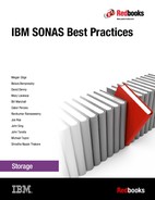
SONAS supports one or two controllers with 0 - 9 expansion enclosures that are SAS connected to each storage node pair, as shown in Figure 4-24.
Figure 4-24 Image of the back of the V7000 controller with nine SAS connected expansions
It is a preferred practice to place the fastest drive technology closest to the controllers in the storage chain. It is also best to use drives from within the enclosure for RAID groups. In this case, using 10 drives in a RAID 6 group leaves an unbalanced number of drives remaining: Two out of 12 or four out of 24 drives in the v7000 enclosure (that can be used as hot spares). However, it is a common and good practice to use RAID 6 over 10 drives with no hot spares and span the 10 drives over multiple enclosures for the RAID group protection.
The current preferred practice is to build 1 managed disk (MDisk) group across each 10-drive RAID 6 group of (8 + P + Q) with a 32 KB segment size. Also, use a 256 KB scatter file system for small files, and span the MDisk groups across the enclosures. Further segment the MDisk and create multiple virtual disks (VDisks) from each MDisk group to create (populate) the file systems and limit the number of VDisks to four or less per MDisk group when possible.
This 256 KB block size considers the most effective capacity use for large groups of small files. When large file sequential workloads are expected and few small files exist, it would be better to use a 1 MB block size with scatter allocation pattern, and build your MDisk RAID 6 groups with a 128 KB segment size.
|
Note: Configure the V7000 logical storage configuration with the command-line interface (CLI) rather than the graphical user interface (GUI). The GUI selects many default values that cannot be overridden. Using the CLI enables you to choose parameters that are better for a SONAS file system (sequential versus striped VDisk, 128 KB strip size, IBM Easy Tier® off, and so on).
|
The following rules must be applied to that part of the Storwize V7000 configuration that is serving the SONAS subsystem:
•MDisks must be RAID arrays (“just a bunch of disks” (JBODs) are not supported).
•All RAID arrays must have redundancy (RAID 0 is not supported).
•All MDisks that are allocated to a single MDisk group must be of the same RAID type and the same drive type with the same performance characteristics. Each unique set of MDisks needs to go into a separate information lifecycle management (ILM) Pool in SONAS. You cannot mix different MDisks of different RAID or drive types in one pool.
•An MDisk group that consists of SSDs is supported.
•The MDisks in each MDisk group must come from the same physical back-end RAID controller.
•Single-port attached RAID systems are supported by the Storwize V7000. However, they are not supported for use with SONAS because of the lack of redundant connections between the Storwize V7000 and the RAID controller.
•The V7000 extent size must be chosen based on the maximum size of the cluster. Use an extent size of 256 MB for the MDisk groups that are used for SONAS storage. Other extent sizes can be used in non-SONAS MDisk groups.
•MDisk sizing and naming are chosen by the user. Follow the guidelines in the Storwize V7000 documentation.
•Storwize V7000 must configure a single host object that contains the worldwide port names (WWPNs) of all of the FC Ports in each of the SONAS storage nodes. This V7000 host object is called SONAS_<serialnumber> where <serialnumber> is the serial number of the SONAS node. This host object is used to map the VDisks that are in use by SONAS to the SONAS nodes.
Using 10-drive groups for RAID 6 (8 + P + Q) helps with drive stripe and write alignment and, as such, follows the preferred practice for data writes. The latency of spanning enclosures does not prove a significant latency over write stripe to storage RAID segment alignment. Therefore, in most cases, it is a preferred practice to use RAID 6 (8 + P + Q).
Design the RAID group to use a segment size that best aligns with the intended file system block and subblock size. This choice is described in Chapter 5, “File system configuration” on page 141.
Separating drives for metadata and data
It is often helpful to separate drives for metadata and data use to help reduce I/O contention to drives during mixed high performance data I/O and heavy metadata scan operations. Heavy normal read and write data access can compete with metadata scans for backup worklists, ILM scans, antivirus, and so on. However, as described in Chapter 5, “File system configuration” on page 141, it is important to recognize that many things are important to consider when you make this decision.
Having enough devices for metadata, along with having enough devices for data, is a delicate balance for many cost-conservative customers. Where extreme performance is not the requirement, it is often advised that sharing devices in the system pool for data and metadata is the best solution, especially when many spindles are used to support the file system.
For clients that require extreme performance where capacity is not the main requirement, it is often helpful to reserve a set of NSDs for metadata only in the system pool. However, when NSDs are set aside for metadata only I/O, and scan time performance is critical to success, it is also important to use multiples of four NSDs per storage node (16) for optimal port and channel saturation.
The HBA port I/O and striping capabilities, and the cache and channel capability of the storage controllers, play a large part in tuned I/O workload balance for data and metadata. So typically, for isolated metadata-only NSDs, the size can be smaller and the quantities should be presented to the file systems in multiples of four per storage node, or optimally 16.
Size is a major consideration for isolated metadata-only NSD devices as well. For example, you can set aside 5% of the file system capacity in drives, and isolate the number of spindles for metadata only, in the system pool. In this configuration, only metadata is hosted by those drives (NSDs) where data-only NSDs are used for data in the system pool.
Using 5% for metadata is a typical sizing, and it includes average file size and typical file count patterns, with GPFS replication of metadata only. If you anticipate a huge number of small files, make that number higher. If you expect a smaller number of larger files, it can be lower. If you choose not to replicate metadata, the size can also be smaller. Plan for more, rather than less, and always replicate metadata across two or more failure groups in GPFS.
In every case where metadata-only devices are to be used for a file system, the preferred practice is to consult a GPFS expert or the SONAS performance team to help make the best choice about what to use and how much to buy.
When SSDs are used for metadata, use RAID 1 or RAID 5 with hot spares, as previously mentioned in this chapter.
Defining volumes
Defining volumes on the V7000 can be done in the GUI or using the CLI. However, defining RAID groups in the GUI always creates the Stripe or Segment size at 256 KB. This does not configure optimal striping for file system subblock-to-storage segment size alignment. See Chapter 5, “File system configuration” on page 141 for block size considerations, and always try to align your storage stripe or chunk size to file system stripe.
It is a preferred practice to configure storage on the Storwize V7000 with the CLI. This practice follows the Storwize V7000 storage guides and Storwize V7000 preferred practice for SONAS gateway solutions, and it offers the best use of that storage platform in most cases.
Considerations for Storwize V7000
The IBM Storwize V7000 Storage configuration behind the SONAS gateway platform is a solution where the storage and the SONAS are independently managed. Therefore, your staff must understand both platforms for overall management of an effective SONAS gateway solution.
The SONAS solution supports only V7000 in the gateway by using internal storage enclosures, and not external V7000 mapped storage for SONAS shares. The Storwize V7000 behind SONAS must be dedicated and not in clustered storage solutions.
The SAN FC switches, and the SAN Volume Controller and Storwize V7000 storage system, are externally managed by using their own native management GUI. As such, the SAN FC switches and the SAN Volume Controller and Storwize V7000 Interface modules are not attached to the internal management network within the SONAS system.
The SAN FC switches and the SAN Volume Controller and Storwize V7000 storage system are externally serviced by using their own native service management interface and any guided maintenance procedures that are provided by these products. As such, the SAN FC switches and the SAN Volume Controller and Storwize V7000 system are not serviced and supported by the SONAS RAS package.
Code and firmware levels
At the time of the writing of this book, the best supported code level on V7000 firmware, for use behind the SONAS, is 7.3.0.7. Before installation, consult your IBM technical advisor (TA) and SSR to ensure that this code is enabled on the Storwize V7000, or to get guidance on currently supported V7000 firmware versions for use behind a SONAS.
Storwize V7000 storage preferred practice summary
This section summarizes the following preferred practices:
•For maximum performance, place only one Storwize V7000 behind each pair of SONAS storage nodes. For maximum capacity, place two Storwize V7000 subsystems behind each storage node pair.
•Never mix Storwize V7000 disk types in the same SONAS disk storage pool.
•Zone the Storwize V7000 with four paths per volume by using single-initiator zoning on the switches (one initiator port per switch zone).
•Zone 4 ports per Storwize V7000 controller with FC Switch redundancy between ports.
•Use large, and consistent, Storwize V7000 volume sizes. 1 TB, 2 TB, or 4 TB volume sizes provide excellent performance and manageability.
•All LUNs that are attached to SONAS must not be usable or seen by any other host.
•Provision groups of four NSDs per storage node to each file system for data or metadata to ensure the highest bandwidth by maximizing use of all ports, buses, channels, and controllers.
•Build the GPFS file system at a 256 KB block size with scatter allocation type for small file workloads, and 1 MB block size with scatter allocation type for large file sequential workloads.
•Create your RAID array segment size to match the file system block stripe. For a file system block size of 256 KB, use a stripe segment size of 32 KB for RAID 6 (8 + P + Q). For file system block size of 1 MB, use a stripe segment size of 128 KB for RAID 6
(8 + P + Q).
(8 + P + Q).
•Provision your storage with global hot spares.
•Review status on both SONAS and Storwize V7000 storage events daily, and manage each as separate storage solutions that are working together to drive your requirements.
•When your primary data storage tier is large-disk (3 TB) NLSAS technology, separate placement of metadata only on SSDs or high-speed SAS disk (in the system pool) to dramatically improve performance when heavy metadata scans are anticipated.
4.2.4 SONAS gateway with DS8000 storage
For the SONAS gateway with DS8000 (RPQ #631-21686), the storage is manually configured and separately managed.
The SONAS gateway solution with DS8000 is especially attractive to customers who decide to use DS8000 storage as their platform of choice. This configuration adds yet another storage tool from the expansive storage platform, and enables the SONAS to be ordered as an independent addition and fabric-connected or direct-connected to the DS8000 for use in a Storwize V7000 Unified platform.
Because of the high-performance capabilities of the IBM DS8000 storage platform, the SONAS can span two or four storage nodes in either single-node or double-node pair solutions to ensure maximum bandwidth and alleviate the storage node pair as a bottleneck (as with XIV Gen3).
However, volumes from the DS8000 can be provisioned only to a single storage node pair. In this scenario, an equal number of volumes are provisioned and distributed across to separate SONAS storage node pairs for preferred-practice, high-performance considerations. Figure 4-25 shows a DS8000 frame.
|
Tip: This configuration is a specialized storage solution for SONAS, and is strictly controlled by RPQ for ensuring the highest success with SONAS subject matter expert (SME) specialist assistance. It requires special resource attention for solution preparation and installation.
|

Figure 4-25 IBM DS8700 frame
Figure 4-26 shows a DS8800 frame.

Figure 4-26 DS8800 frames image
Connectivity to the Storage node pairs is managed using LC-to-LC Fibre Channel cable (see Figure 4-27).

Figure 4-27 DS8000 connectivity chart
Figure 4-28 shows a DS8000-to-SONAS configuration.

Figure 4-28 SONAS to DS8000 connection overview
Figure 4-29 and Figure 4-30 show a sample zoning configuration for this solution.

Figure 4-29 Switch 1 zone list

Figure 4-30 Switch 2 zone list
Because the DS8000 with SONAS is a highly specialized solution, and has limited engagements in the field today, only a brief description is provided. Work with IBM to engage subject matter experts for this solution.
DS8000 storage preferred practice summary
This section summarizes the preferred practices for DS8000 storage:
•For maximum performance, place only one DS8000 behind each set of four SONAS storage nodes. For maximum capacity, place two DS8000s behind each set of storage nodes. The DS8000 can be placed behind a single pair of storage nodes for maximum capacity at lowest cost, at reduced performance ceilings.
•Never mix DS8000 disk types in the same SONAS disk storage pool.
•Zone the DS8x00 with four paths per volume by using single-initiator zoning on the switches (one initiator port per switch zone).
•Use large and consistent DS8000 volume sizes. 1 TB, 2 TB, or 4 TB provide excellent performance and manageability.
•All LUNs that are attached to SONAS must not be usable or seen by any other host.
•Provision groups of four NSDs per storage node to each file system for data or metadata to ensure the highest bandwidth by maximizing use of all ports, buses, channels, and controllers.
•Build the GPFS file system at a 256 KB block size with scatter allocation type for small file workloads, and a 1 MB block size with scatter allocation type for large file sequential workloads.
•Create your RAID array segment size to match the file system block stripe. For a file system block size of 256 KB, use a stripe segment size of 32 KB for RAID 6 (8 + P + Q). For a file system block size of 1 MB, use a stripe segment size of 128 KB for RAID 6
(8 + P + Q).
(8 + P + Q).
•Provision your storage with global hot spares.
•Review status on both SONAS and DS8x00 storage events daily, and manage each as separate storage solutions that are working together to drive your requirements.
•When your primary data storage tier is large-disk (3 TB) NLSAS technology, separate placement of metadata only on SSDs or high-speed SAS disk (in the system pool) to dramatically improve performance when heavy metadata scans are anticipated.
4.2.5 SONAS gateway with IBM DCS3700
For the SONAS gateway with IBM DCS3700 (FC 9008), the storage is manually configured, and independently managed.
The IBM DCS3700 storage with a SONAS gateway offers a highly flexible storage configuration, plus high-density storage in a small footprint. The IBM DCS3700 offers a wide variety of drive options with the inclusion of SSD for high performance. This selection can bring you great flexibility and performance with a small footprint, and at the lowest potential price per terabyte. The IBM DCS3700 storage solution enables for capacity to be added in 10-drive increments with a minimum of 20 drives per enclosure.
|
Note: The IBM DCS3700 must be installed in customer-provided frames and managed independently of the SONAS storage frame solution. It requires a DS Host Manager for initial configuration, management, and monitoring. The addition of an IBM DCS3700 Remote Storage Manager server is also required for call home support.
|
The following performance and flexibility benefits are provide by SONAS DCS3700 gateway solutions:
•This solution offers great flexibility in disk speeds, drive technology types, and drive size options with a highly flexible management of incremental growth. It enables for flexible storage tiering with the storage pod between SSD, SAS, and Near Line SAS storage options, and incremental growth in 10-drive increments from a 20-drive minimum.
•The IBM DCS3700 solution is also currently one of two possible solutions that accommodate support for an SSD tier of SONAS storage. The other solution is Storwize V7000. It is a preferred-practice solution for supporting a cheap and deep NLSAS drive storage tier for data storage with SSD dedicated for metadata.
With one or two controllers that support 0, 1, or 2 expansion enclosures behind it, it offers the highest overall capacity at the smallest footprint in the SONAS gateway solution offerings. It uses 3 TB or 4 TB NLSAS drives, and 60 drives per enclosure for file system capacity depth.
The SONAS gateway configurations are sent in pre-wired racks that are made up of Internal switching components for the SONAS Interface nodes (with Integrated Management services) and SONAS Storage nodes. The storage is sold and framed separately. The solutions do not provide for cross-frame connectivity between SONAS, fabric, and storage. It is something that you must plan for independently. This section can help you accomplish that goal with the highest level of success. Figure 4-31 shows the SONAS gateway base frame.

Figure 4-31 The SONAS gateway base frame lines up interface nodes from the frame bottom
IBM DCS3700 enclosures support up to 60 drives in each enclosure. All storage must be assembled and installed in a customer-provided frame and not the SONAS frames (see Figure 4-32).

Figure 4-32 SONAS base frame plus client DCS3700 frames
Types of enclosures
There are effectively four types of IBM DCS3700 enclosures supported by the SONAS gateway. These types are 1818-80C, 1818-80E, 2851-DR2, and 2851-DE2. Each enclosure can hold up to 60 drives. The following list provides an explanation of each type:
•1818-80C. This type is an IBM DCS3700 controller enclosure that is ordered separately from the SONAS gateway solution. The 1818-80C is not directly linked to the SONAS gateway solution, but is supported when the minimum configuration and code levels (nonvolatile random access memory (NVRAM), and firmware) are met.
•1818-80E. This type is an IBM DCS3700 expansion enclosure that is ordered separately from the SONAS gateway solution. The 1818-80E is not directly linked to the SONAS gateway solution, but is supported when the minimum configuration and code levels (environmental service modules (ESMs)) are met.
•2851-DR2. This type is an IBM DCS3700 controller enclosure that is ordered with or specifically for a SONAS gateway. Though ordered as a separate line item, the 2851-DR2 is directly linked to the SONAS gateway and includes the correct code levels. It is ready to be integrated into a SONAS gateway solution.
•2851-DE2. This type is an IBM DCS3700 expansion enclosure that is ordered with or specifically for a SONAS gateway. Though ordered separately, the 2851-DE2 is directly linked to the SONAS gateway and includes the correct code levels. It is ready to be integrated into a SONAS gateway solution.
|
Note: Though the 1818 and 2851 are both supported by a SONAS gateway, the 1818 and 2851 models are not compatible with each other, and are not interchangeable. A 2851-DE2 cannot be used as an expansion enclosure for an 1818-80C enclosure. Likewise, an 1818-80E enclosure cannot be used as an expansion enclosure for a 2851-DR2.
|
Expect to start with a minimum of 60 drives behind SONAS, and grow in increments of 10 drives. However, plan for growth wisely. rather than adding storage on a quarterly basis, it is wise to grow in targets of semi-annual or annual growth. This approach not only simplifies and decreases the number of maintenance operations that are required for upgrade and expansion, but it also reduces the cumulative burden of normal I/O competing with each data redistribution or restripe operation.
IBM DCS3700 is only supported in direct connection configurations (not fabric switch connections), so zoning is not a concern with this solution.
Gateway storage cannot be placed in SONAS frames
The storage must be configured independent of the SONAS and before SONAS initial configuration. All IBM DCS3700 product preferred practices for use on Red Hat Enterprise Linux (RHEL) clustered servers should be adhered to as a component of preferred practice in use with SONAS attachment.
The SONAS with IBM DCS3700 gateway configuration is not a unified storage platform and it is not supported to use part of the storage for other block or NAS clients. This restriction means that you can connect only one or two IBM DCS3700 controllers to any SONAS storage node pair, although you can use multiple storage node pairs to extend IBM DCS3700 storage in your SONAS solution. Figure 4-33 provides an orientation of the IBM DCS3700.

Figure 4-33 IBM DCS3700 component orientation
The IBM DCS3700 controllers and expansion enclosures are 60-drive enclosures that consist of five 12-drive trays in each enclosure (see Figure 4-34). In partial population configurations, it is mandatory to fill the front four drive slots in each tray to ensure correct system cooling and enable correct air flow. Therefore, the minimum drive capacity that is allowed in an IBM DCS3700 enclosure is 20 drives.

Figure 4-34 IBM DCS3700 4U chassis and drive trays
IBM DCS3700 supports two types of controllers
IBM DCS3700 storage supports the following types of controllers:
•The controller that is based on the IBM DS3500 controller that supports 4 GB or 8 GB of Cache, and the drive types, are shown in Figure 4-35. This controller supports up to two expansion enclosures for a total of three enclosures and up to 180 drives. This configuration is supported in SONAS 1.3.2 and later.
•The Performance Module option Feature code 3100 is based on the IBM DS5000™ controller and supports cache sizes of 12 GB, 24 GB, or 48 GB. This controller supports up to five expansion enclosures for a total of six enclosures and up to 360 drives. This configuration is supported in SONAS 1.4.1 and later.

Figure 4-35 Drive types that are supported by the SONAS gateway IBM DCS3700 controller
Connectivity is only supported using direct connect between the SONAS storage nodes and the IBM DCS3700 controllers. Currently, one or two IBM DCS3700 controllers are supported behind each SONAS storage node pair. The IBM DCS3700 base controller supports up to two expansion enclosures, where the IBM DCS3700 Performance Module supports up to five expansion enclosures.
Each storage node has two connections to each controller enclosure, providing two paths to every volume, as shown in Figure 4-36 and Figure 4-37.

Figure 4-36 SONAS gateway with a single IBM DCS3700 and one expansion cable connectivity map

Figure 4-37 SONAS gateway with a single IBM DCS3700 and two expansion cables connectivity map
Figure 4-38 shows the preferred-practice configuration with SONAS storage nodes. The cables in blue are LC-to-LC Fibre Channel cables, where the brown lines are showing SAS cables from the controller to the expansion unit, and from the first expansion unit to the second expansion unit.

Figure 4-38 SONAS storage node cable connections with two separate controllers
IBM DCS3700 configuration
The IBM DCS3700 is initially configured before it is added to the SONAS storage nodes. Follow the IBM System Storage DCS3700 Installation Guide for configuring the IBM DCS3700, by using the IBM DS Storage Manager 10.84 software (or the latest supported). On a customer-managed server, configure the IBM DCS3700 controller IP addresses, storage pool, arrays, and volumes before you connect and provision the SONAS storage nodes. The storage installation follows the process in the IBM System Storage DCS3700 Storage Subsystem and DCS3700 Storage Subsystem with Performance Module Controllers Installation, User's, and Maintenance Guide, GA32-0959.
The SONAS storage node is added to the IBM DCS3700 as a cluster of two nodes (the SONAS storage node pair). The storage nodes are added by their connected Fibre Channel HBA WWPNs. They can be found on a sticker in the back of each SONAS Storage or by running cn_get_wwpns on the SONAS management node.
They can also be detected from the IBM DCS3700 after the storage node FC cable is connected and the SONAS storage nodes are powered on. The connection is made between the SONAS and the previously configured IBM DCS3700 by using the SONAS Gateway Installation Guide. This process is typically done by the IBM solution installation team.
The storage nodes are added to the defined cluster, and the volumes are mapped to the cluster rather than the individual nodes (this mapping is the preferred practice).
When mapping volumes of one IBM DCS3700, a Lun0 device ID can be mapped to the SONAS cluster. However, it is a preferred practice to avoid mapping the Lun0 device ID for the second IBM DCS3700 behind any SONAS storage node pair to avoid issues in LUN discovery on the SONAS side.
Creating file systems with SONAS gateway IBM DCS3700 devices
For best performance with highly random I/O workload profiles, use SAS drive technology for the file system that you are planning to serve. The more, the better, because GPFS distributes I/O evenly between them all.
Generally, you also spread all data and metadata across all the SAS drives to ensure adequate capacity for both data and metadata in the system pool and enable the full distribution to support sharing high-performance through even striping.
When extremely high file system scanning operations are expected, such as extremely high-frequency operations of replication, backup, snapshots, and snapshot deletions, there can be an advantage to isolating the metadata devices from the data devices to remove contention between operation types. In this case, it is important to make sure that you have enough devices for both types of data.
Assuming that file types and sizes are a mixed average of most common scenarios, you can assume that you need approximately 5% of the overall data set size for metadata. This configuration assumes that metadata replication is wanted. In this case, a 100 TB file system capacity requires a 5 TB metadata capacity.
This allocation can be an effective way to improve your scan time on otherwise busy file systems. However, if that 5 TB comes from only a few spindles, there might not be enough read and write heads or I/O channels to handle the heavy random reads and writes of a common metadata workload pattern. In this case, you still need to make sure that you have enough spindles and volumes to manage both capacity and performance for the smaller metadata component of the system pool:
•Create at least 16 equally-sized LUNs in the pool that houses the GPFS metadata, even if this process requires creating smaller LUNs than specified in Figure 4-35 on page 132.
•High-performance SAS disk drives can be helpful for building high-performance on 10,000 and 15,000 RPM SAS disks drives in RAID 6 (8 + P + Q) arrays.
•For system availability reasons, consider having some number (a 10-pack) of high-performance SAS disk drives in the IBM DCS3700 system available as hot spares for RAID rebuilds.
•One or more 10-packs of SAS disks drives can be ordered on the IBM DCS3700 by ordering FC 3400 (for example, a 300 GB 15 K SAS HDD 10 pack).
High capacity Nearline SAS disk drives
Configure high-capacity 7.2K RPM Nearline SAS disks drives in RAID 6 8 + P + Q arrays.
A single logical drive (LUN) should be created out of the available space on each RAID array using the IBM DS Storage Manager. For system availability reasons, consider having some number (a 10-pack) of high capacity 7.2 K RPM Nearline SAS disk drives in the IBM DCS3700 system available as hot spares for RAID rebuilds.
One or more 10-packs of high capacity Nearline SAS disks drives can be ordered on the IBM DCS3700 by ordering FC 3450.
Disk pools
A new feature of IBM DCS3700 called Dynamic Disk Pools (DDP) or just disk pools, is now supported by SONAS release 1.4.1. DDP dynamically distributes data, spare capacity, and protection information across a pool of disk drives. DDP is designed to deliver and maintain predictable performance under all conditions, including recovering from drive failures.
These pools can range in size from a minimum of 11 drives to potentially as large as all of the drives in the IBM DCS3700 storage systems. There are no spare drives, only spare capacity. In other words, there are no idle drives; every drive participates.
The four key tenets of DDP technology are:
•Elimination of complex RAID management
•No idle spares to manage
•No reconfiguring of RAID when expanding
•Significant reduction of performance effect after a drive failure (or multiple drive failures) when compared to traditional RAID schemas
LUNs that are created from a disk pool are configured as RAID 6 LUNs and a segment size of 128 KB (the segment size cannot be changed). However, unlike RAID 6 arrays, LUNs that are created from disk pools share all disks within the pool. The advantage of disk pools is that rebuild times are greatly reduced, and the effect of a drive rebuild on any LUN is greatly reduced. Consider disk pools when you configure IBM DCS3700 storage for SONAS. The drives within each disk pool must be of the same type, size, and speed. SSDs cannot be in a disk pool.
Configure disk pools in groups of 10 (the minimum is 11). This setting is because LUNs are created as RAID 6 devices (8 + P + Q). A larger disk pool has a smaller percentage of capacity allocated to reserved capacity, and is affected less by a rebuild. In a typical configuration, the minimum disk pool is 40 disks. Make the number of equally sized LUNs the number of disks in the disk pool divided by 10 (for example, 40 / 10 = 4).
Also, remember to allocate LUNs in fours (4, 8, 12, and so on) to evenly distribute the LUNs across storage nodes and storage controllers. It is also important to note that LUNs are created in 4 GB chunks. Therefore, make the LUN size evenly divisible by 4 GB to maximize the used capacity of the disk pool.
Determining the most space-efficient DDP LUN size
This section provides an example of determining the most space-efficient LUN size:
1. Look at the Free Space (in the GUI) after the pool is created (for example, 53.246 TB).
2. Convert to GB (53.246 * 1024 = 54,523.904).
3. Divide by 4 (4 GB chunk) and drop the remainder (54,523.904 / 4 = 13,630).
4. Divide by the number of LUNs and drop the remainder (13,630 / 4 = 3,407).
5. Multiply by 4 (4 GB chunk) (3,407 * 4 = 13,628 GB).
6. Create 4 LUNs that are 13,628 GB or 13.308 TB.
Solid-state disks
It is becoming popular to use NLSAS for data stores, and SSD for improving scan rates of the metadata.
For the maximum performance from metadata scans, configure solid-state disks in RAID 1
2 + 2 hot spare, RAID 5, or RAID 10 2 + 2 + HS arrays. A single logical drive (LUN) is optimal for available space on each RAID array. However, for best performance, use 8 or 16 NSDs on the SONAS for maximum port and channel saturation. It is common to split the difference with two mapped LUNs from each of four or eight array groups for metadata, and use the IBM DS Storage Manager to create and map them.
2 + 2 hot spare, RAID 5, or RAID 10 2 + 2 + HS arrays. A single logical drive (LUN) is optimal for available space on each RAID array. However, for best performance, use 8 or 16 NSDs on the SONAS for maximum port and channel saturation. It is common to split the difference with two mapped LUNs from each of four or eight array groups for metadata, and use the IBM DS Storage Manager to create and map them.
For maximum protection, evenly divide the NSDs across two controller-based failure groups and replicate metadata with your GPFS file systems.
Order SSDs in groups of five, so that with each group of five SSDs, you have one RAID 1 (2 + 2 array, plus a hot spare SSD). Use the 400 GB SAS 2.5-inch SSD model for improved capacity.
Solid-state disk preferred practices
Because the most common use case for solid-state disks is for GPFS file system metadata, order a minimum of two groups of five (a total of 10 SSDs).
These two groups of five SSDs support the following configuration:
•One group of five SSDs can be used to create a RAID-10 2 + 2 array (with a spare SSD set aside in a global spare pool). One logical drive is created out of the RAID array, and the GPFS NSD that corresponds to this logical drive are assigned to one GPFS failure group.
•Another group of five SSDs can be used to create another RAID-10 2 + 2 array (with a spare SSD set aside in a global spare pool). One logical drive is created out of the RAID array and the GPFS NSD that corresponds to this logical drive assigned to a different GPFS failure group.
If you are going to use solid-state disks specifically for GPFS file system metadata, you need to estimate the amount of space that is needed for GPFS file system metadata.
Code and firmware levels
At the current date (date of this release), the best-supported IBM DCS3700 code level for use behind SONAS is IBM DS Storage Manager = 10.86.G5.x and FW= 7.86.46.00. Ask your IBM SSR to ensure that this code is enabled on the IBM DCS3700s before the SONAS installation, and inquire what the current SONAS release suggests for the IBM DCS3700 firmware.
IBM DCS3700 storage preferred practice summary
This section summarizes the preferred practices for IBM DCS3700 storage:
•Place one IBM DCS3700 behind each storage node pair for best performance to capacity scaling.
•For maximum performance, place only one IBM DCS3700 behind each pair of SONAS storage nodes. For maximum capacity, place two IBM DCS3700 subsystems behind each storage node pair.
•Never mix IBM DCS3700 disk types in the same SONAS disk storage pool.
•Use large, and consistent, IBM DCS3700 volume sizes of 1 TB, 2 TB, or 4 TB (the preferred practice is to have one logical drive per RAID 6 array) to provide performance and manageability. Smaller volume sizes are preferred for metadata-only solutions.
•Use Dynamic Disk Pools (disk pools) where possible. Ensure that disk pools are a minimum of 40 disks and must be the same type, size, and speed.
•If only the control enclosure is present in a controller string, the following guidelines apply:
– Configure RAID 6 groups to contain no more than two drives per tray .
– Configure RAID 5 SSD groups as 4 + P arrays, with one drive per tray, rather than an
8 + P + S array .
8 + P + S array .
– Configure RAID 1 and RAID 10 groups such that no mirror drives are contained in the same tray and hot spares are available.
•Higher-availability characteristics are achieved when one or more expansion enclosures are present in a controller string. If one or more expansion units are present in a controller string, apply the following guidelines:
– Configure RAID 5 and RAID 6 groups to contain only one drive per tray .
– Configure RAID 1 and RAID 10 groups such that no mirror drives are contained in the same tray.
The two preceding guidelines are generally the default choices that are made by the Create Array and Disk Pool wizard in the IBM DCS3700 Storage Manager GUI when automatic configuration is used. However, depending on the number and type of drives present, their physical locations, and previously created arrays, this selection might not always occur. If you are concerned about availability, verify the drive selections in each array manually.
•All LUNs that are attached to SONAS must not be allocated or seen by any other host.
•Provision groups of four NSDs per storage node to each file system for data or metadata to ensure the highest bandwidth by maximizing use of all ports, buses, channels, and controllers.
•Build the GPFS file system at 256 KB block size with the scatter allocation type for small file workloads, and the 1 MB block size with the scatter allocation type for large file sequential workloads.
•Create your RAID array segment size to match the file system block stripe. For a file system block size of 256 KB, use a stripe segment size of 32 KB for RAID 6 (8 + P + Q). For a file system block size of 1 MB, use a stripe segment size of 128 KB for RAID 6
(8 + P + Q).
(8 + P + Q).
•Provision your storage with global hot spares.
•Review the status on both SONAS and IBM DCS3700 storage events daily, and manage each as separate storage solutions that are working together to drive your requirements.
•When your primary data store tier is large disk (3 TB) NLSAS technology, separate placement of metadata only on SSDs or high-speed SAS disk (in the system pool) to dramatically improve performance when heavy metadata scans are anticipated.
4.3 Failure groups and storage pools
This section provides an overview of failure groups and storage pools, and a few preferred practices.
4.3.1 Failure groups
GPFS disk failure groups are means of enabling GPFS to manage groups of NSDs with special care (such as synchronous replication of data, or metadata, or both). It is yet another layer of flexibility, power, and protection that is offered by GPFS to the SONAS and Storwize V7000 Unified storage platforms.
The preferred practice is that, whenever possible, you provision all metadata storage evenly into two separate failure groups to support the use of GPFS replication, when and if that level of extra protection is wanted or deemed necessary.
Also understand that synchronous replication adds mirroring of data that is often already adequately protected in an intelligent storage RAID set protection. Using it often adds a significant burden to write performance. Carefully consider this option and expert advice before making these decisions and creating the initial file system.
If replication is created to support the file system write activity at onset or creation time, it can be turned off subsequent to activating file shares non-disruptively.
4.3.2 Storage pools
Storage pools are a means of keeping separation in the types (tiers) of storage that are used by GPFS in SONAS or Storwize V7000 Unified storage platforms.
|
Tip: If all storage is placed in the default failure group 1 only, no GPFS based synchronous replication can exist. However, if all devices are evenly distributed across 2 or more failure groups, the choice about whether to replicate that data or metadata can be made at any time.
|
Typically, different tiers of storage or storage types are added into different storage pools (or tiers) except for the system pool. The system pool is the default primary data placement pool and the default placement pool for metadata. It is possible to have SSD in the system pool with a data usage type tag of metadataOnly, while SAS or NLSAS devices are placed in the system storage pool with a data usage tag dataOnly.
Changes to disk pools and types must be made before you allocate devices to the file system.
If you are intermixing different storage vendors behind a SONAS (that is, DDN and IBM DCS3700), use different storage pools within the same file system to separate the different drive vendors and technologies. Placement and migration policies are a powerful way to use multiple pools and direct your data to the storage pool that you want.
For example, “hot” data can remain on a 15 K SAS disk pool, while “cold” data can move to a high capacity Nearline pool. There are many possibilities that you can consider when you intermix storage types and careful thought is critical for a successful deployment.
|
Tip: Metadata can be placed only in the system pool. Therefore, all other storage pools can contain dataOnly usage types.
|
..................Content has been hidden....................
You can't read the all page of ebook, please click here login for view all page.