

Hardware configurations and upgrade considerations
This chapter includes the following sections:
6.1 TS7700 Virtualization Engine hardware components
IBM TS7700 Virtualization Engine Release 3.2 of Licensed Internal Code (LIC) runs only on a 3957 model V07/VEB. These models are based on an IBM POWER7 processor-based server with I/O expansion drawers and Peripheral Component Interface Express (PCI-e) adapters. The hardware platform enhances the performance capabilities of the subsystem compared to the previous implementation. It also makes room for future functions and enhancements.
This section describes the hardware components that are part of the TS7700 Virtualization Engine. These components describe the TS7720 disk-only solution, TS7720T, and TS7740 Virtualization Engine, which are attached to an IBM System Storage TS3500 Tape Library configured with IBM 3592 tape drives.
The TS7720 Virtualization Engine contains the following components:
•One IBM 3952 model F05 Tape Base Frame, which houses the following components:
– One TS7720 Virtualization Engine server
– Two TS7700 Server Expansion Unit input/output (I/O) drawers (Primary and Alternative)
– One TS7720 Virtualization Engine Encryption Capable 3956-CS9 Cache Controller with up to nine optional TS7720 Virtualization Engine Encryption Capable 3956-XS9 Cache Expansion Drawers
– Two Ethernet switches
– One TS3000 Total System Storage Console (TSSC)
•One or two optional 3952 Storage Expansion Frames, housing the following components:
– One TS7720 Virtualization Engine Encryption Capable 3956-CS9 cache drawer
– Up to 15 optional TS7720 Virtualization Engine Encryption Capable 3956- XS9 Cache Expansion Drawers
– Up to four cache strings housed within all the frames
The TS7720T Virtualization Engine contains the following components:
•One IBM 3952 model F05 Tape Base Frame, which houses the following components:
– One TS7720T tape-attached Virtualization Engine server
– Two TS7700 Server Expansion Unit I/O drawers (Primary and alternative)
– One TS7720 Virtualization Engine Encryption Capable 3956-CS9 Cache Controller with up to nine optional TS7720 Virtualization Engine Encryption Capable 3956-XS9 Cache Expansion Drawers
– Two Ethernet switches
– One TS3000 Total System Storage Console (TSSC)
•One or two optional IBM 3952 Storage Expansion Frames, which house the following components:
– One TS7720 Virtualization Engine Encryption Capable 3956-CS9 cache drawer
– Up to 15 optional TS7720 Virtualization Engine Encryption Capable 3956- XS9 Cache Expansion Drawers
– Up to three cache strings housed within all the frames
•Connection to a TS3500 Tape Library with 4 - 16 IBM 3592 Tape Drives and two Fibre Channel (FC) switches
The TS7740 Virtualization Engine contains the following components:
•One IBM 3952 model F05 Tape Base Frame, which houses the following components:
– One TS7740 Virtualization Engine server
– Two TS7700 Server Expansion Unit I/O drawers (Primary and alternative)
– One TS7740 Virtualization Engine Encryption Capable 3956-CC9 Cache Controller with zero, one, or two TS7740 Virtualization Engine Encryption Capable 3956-CX9 Cache Expansion Drawers
– Two Ethernet switches
– One TS3000 System Console (TSSC)
•Connection to a TS3500 Tape Library with 4 - 16 IBM 3592 Tape Drives and 2 Fibre Channel switches
6.1.1 Common components for the TS77000 Virtualization Engine models
The following components are common for models of the TS7700 Virtualization Engine.
IBM 3952 Tape Base Frame
The IBM 3952 Tape Base Frame Model F05 is a frame that provides up to 36U (rack units or Electronics Industry Association (EIA) units) of usable space. The rack units contain the components of the defined tape solution. The 3952 Tape Base Frame is not a general-purpose frame. It is designed to contain only the components of specific tape offerings, such as the TS7740, TS7720, and TS7720T tape attach Virtualization Engines.
Only components of one solution family can be installed in a 3952 Tape Base Frame. The 3952 Tape Frame is configured with a Dual AC Power Supply feature for redundancy.
|
Note: Available by request for price quotation (RPQ) is a top exit for cables in the IBM 3592 Tape Base Frame.
|
In a TS7700 Virtualization Engine configuration, the 3952 Tape Base Frame is used for the installation of the following components:
•The TS7700 Virtualization Engine Server
•Two TS7700 Server Expansion Unit I/O Drawers (Primary and Alternate)
•The TS7700 Virtualization Engine Cache Controller
•The TS7700 Virtualization Engine Optional Cache Expansion Drawers
•Two Ethernet switches
•The TS3000 System Console
These components are described in detail for the TS7700 Virtualization Engine specific models in the following sections.
TS3000 System Console (TSSC)
The TS3000 Total Storage System Console (TSSC) is a required component for the TS7700 Virtualization Engine. It can be a new console or an existing TSSC. A new TSSC can be installed in the TS7700 Virtualization Engine 3952-F05 Base Frame or another existing rack.
When a TSSC is ordered with a TS7700 Virtualization Engine, it is usually preinstalled in the 3952-F05 frame. The new model TSSC released in R3.2 is a 1U server x3250 M4 M/T 2583 and includes a new keyboard, video monitor, and mouse. It is supported with TSSC code level 7.4.x.
Ethernet switches
Previous Ethernet routers are replaced by 1 gigabit (Gb) Ethernet (GbE) switches in all new TS7700 Virtualization Engines. The switches, a primary and alternative, are used in the TS7700 internal network communications.
The communications to the external network use a set of dedicated Ethernet ports on adapters in the 3957 server. Internal network communications (interconnecting TS7700 switches, TSSC, Disk Cache System, and TS3500 when present) use their own set of Ethernet ports on adapters in the expansion I/O drawers.
Communications were previously handled by the routers, including Management Interface (MI) addresses and encryption key management. The virtual Internet Protocol (IP) address previously provided by the router’s translation capability is now implemented by virtual IP address (VIPA) technology.
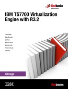
When replacing an existing TS7700 Virtualization Engine Model V06/VEA with a new V07/VEB model, the old routers stay in place. However, they are reconfigured and used solely as regular switches. The existing external network connections are reconfigured and connected directly to the new V07/VEB server. Figure 6-1 shows the new 1 Gb switch and the old Ethernet router for reference.
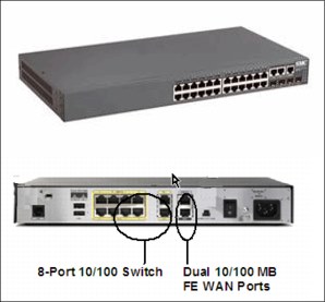
Figure 6-1 New switch (top) and old router (bottom)
TS7700 Virtualization Engine grid adapters
The connection paths between multiple TS7700 Virtualization Engines in a grid configuration are the two grid adapters in slot one of the I/O expansion drawers. The dual-ported 1 gigabits per second (Gbps) Ethernet adapters can be copper RJ45 or optical fiber (shortwave). These optical adapters have an LC duplex connector.
Depending on your bandwidth and availability needs, TS7700 Virtualization Engine can be configured with two or four 1-Gb links. Feature Code 1034 (FC1034) is needed to enable the second pair of ports in the grid adapters. These ports can be either fiber shortwave (SW) or copper. Also, there is a choice of two longwave (LW) single-ported Optical Ethernet adapters (FC1035) for two 10-Gb links. Your network infrastructure must support 10 Gbps for this selection. The adapter does not scale down to 1 Gbps.
The Ethernet adapters cannot be intermixed within the same cluster, they must be of the same type (same feature code).
TS7700 Virtualization Engine Server models (3957-V07/VEB)
The engine server consists of an IBM System POWER7 processor-based server and two new expansion drawers for I/O adapters. This replaces the original IBM POWER® 5 ++ and the I/O drawers from the V06/VEA version. The TS7700 Virtualization Engine Server controls virtualization processes such as host connectivity and device virtualization. It also controls the internal hierarchical storage management (HSM) functions for logical volumes and replication.
Figure 6-2 shows the front view of the new TS7700 Virtualization Engine Server models 3957-V07/VEB.

Figure 6-2 TS7700 Virtualization Engine Server models 3957-V07/VEB (front view)
The TS7700 Virtualization Engine Server V07/VEB offers the following features:
•Rack-mount (4U) configuration.
•One 3.0 gigahertz (GHz) 8-core processor card.
•16 gigabytes (GB) of 1066 megahertz (MHz) error checking and correcting (ECC) memory (32 GB when 8 Gb Fibre Channel connection (FICON) is present).
•Eight small form factor (SFF) direct access storage device (DASD): Four disk drives are assigned to an internal serial-attached SCSI (SAS) controller. The other four disk drives are assigned to an external SAS adapter, providing redundancy.
•The following integrated features:
– Service processor
– Quad-port 10/100/1000 megabits (Mb) Ethernet
– IBM EnergyScale™ technology
– Hot-swap capability and redundant cooling
– Two system (serial) ports
– Two Hardware Management Console (HMC) ports
– Two system power control network (SPCN) ports
– One slim bay for a DVD-RAM
•Five hot-swap slots:
– Two PCIe x8 slots, short card length (slots 1 and 2)
– One PCIe x8 slot, full card length (slot 3)
– Two PCI-X DDR slots, full card length (slots 4 and 5)
The hot-swap capability is only for replacing an existing adapter with another of the same type. It is not available when changing adapter types in a machine upgrade
or change.
or change.
•SAS hard disk drives: TS7700 uses eight disk drives. Four disks mirror one SAS adapter, and the other four backup drives are assigned to a separate SAS adapter.
•A SAS card is used for the mirroring and SAS controller redundancy. It has an external cable for accessing the mirrored disks.
Each new Expansion Unit I/O Adapter Drawer offers six extra PCI-X or PCI Express adapter slots:
•One or two 4 Gb FICON adapters per I/O Expansion Drawer, total of two or four FICON adapters per cluster. Adapters can work at 1, 2, or 4 Gbps. FICON card must be of the same type within one cluster.
•One or two 8 Gb FICON adapters per I/O Expansion Drawer, total of two or four FICON adapters per cluster. Adapters can work at 2, 4 or 8 Gbps. FICON card must be of the same type within one cluster. 8 Gb FICON card requires FC 3462, 16 gigabyte (GB) memory upgrade. All servers with 8 Gb FICON adapters require 32 GB of memory, an increase of 16 GB of memory to the default server configuration.
•Grid Ethernet card (PCI Express). Grid Ethernet can be copper or fiber (1 or 10 Gbps).
•8 Gbps Fibre Channel to disk cache (PCI Express).
•8 Gbps Fibre Channel PCI Express connection to tape in a TS7740 and TS7720T or
8 Gbps Fibre Channel PCI Express for connection to TS7720 Expansion frames.
8 Gbps Fibre Channel PCI Express for connection to TS7720 Expansion frames.
Additional memory upgrade (FC 3462)
The 3957-V07/VEB server features 16 GB of physical memory in its basic configuration. The new FICON 8 Gb adapters (introduced in Licensed Internal Code (LIC) R3.1) require an extra 16 GB of random access memory (RAM) in the 3957-V07/VEB server, for a total size of 32 GB of RAM. This additional capacity is only supported on R3.1 or higher level of code.
6.1.2 TS7720 Virtualization Engine components
The TS7720 Virtualization Engine is a disk-only Virtualization Engine. It provides most of the benefits of the TS7740 Virtualization Engine without physical tape attachment. The TS7720 Virtualization Engine can be used to write tape data that does not need to be copied to physical tape. This enables access to the data from the Virtualization Engine Cache until the data expires.
TS7720 Virtualization Engine Release 3.2 consists of a 3952 Model F05 Encryption Capable Base Frame and one or two optional 3952 Model F05 Encryption Capable Storage Expansion Frames. FC5272 enables full disk encryption on the VEB. FC7404 is needed to enable full disk encryption on each cache drawer. After it is enabled, full disk encryption cannot be disabled.
The 3952 Model F05 Tape Base Frame houses the following components:
•One TS7720 Virtualization Engine Server, 3957 Model VEB.
•Two TS7700 Expansion Unit I/O Drawers (Primary and alternative).
•One TS7720 Virtualization Engine Encryption Capable SAS Cache Controller 3956-CS9. The controller has zero to nine TS7720 Virtualization Engine Encryption Capable SAS 3956- XS9 Cache Expansion Drawers. The base frame must be fully configured before adding a first storage expansion frame.
•Two Ethernet switches.
The 3952 Model F05 Storage Expansion Frame houses one TS7720 Virtualization Engine Encryption Capable SAS Cache Controller 3956-CS9. Each controller can have 0 - 15 TS7720 Virtualization Engine Encryption Capable SAS 3956-XS9 Cache Expansion Drawers. The first expansion frame must be fully configured before adding a second storage expansion frame.
Each TS7720 Virtualization Engine SAS Cache Controller, 3956 Model CS9 using 3 terabyte (TB) drives, provides approximately 23.86 TB of capacity after RAID 6 formatting. The TS7720 Virtualization Engine SAS Cache Drawers, 3956 Model XS9 using 3 TB drives, provides approximately 24 TB of capacity after Redundant Array of Independent Disks
(RAID 6) formatting. The TS7720 uses global spares, enabling all expansion drawers to share a common set of spares in the RAID 6 configuration.
(RAID 6) formatting. The TS7720 uses global spares, enabling all expansion drawers to share a common set of spares in the RAID 6 configuration.
The base frame, first expansion frame, and second expansion frame are not required to be of the same model and type. Only when the base frame is of the CS9 type is it required to be fully populated when adding an expansion frame. When adding a second expansion frame, the first expansion frame must be fully populated if containing CS9 technology.
Using 3 TB disk drives, the maximum configurable capacity of the TS7720 Virtualization Engine at R3.2 with the 3952 Model F05 Storage Expansion Frame is 1007.86 TB of data before compression.
Figure 6-3 shows the TS7720 Virtualization Engine Base Frame components.
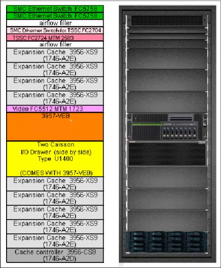
Figure 6-3 TS7720 Virtualization Engine Base Frame components
Figure 6-4 shows the TS7720 Virtualization Engine Expansion Frame components.
Figure 6-4 TS7720 Virtualization Engine Expansion Frame components
TS7720 Virtualization Engine Cache Controller (3956-CS9)
The TS7720 Virtualization Engine Encryption Capable Cache Controller, 3956 Model CS9, is a self-contained 2U enclosure. It mounts in the 3952 Tape Base Frame and the optional 3952 Storage Expansion Frame. Figure 6-5 shows the TS7720 Virtualization Engine Cache Controller from the front (left side) and rear (right side). The rear view details the two separated controllers used for access redundancy and performance (Controller A on left and Controller B on the right side).
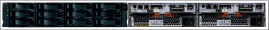
Figure 6-5 TS7720 Virtualization Engine Encryption Capable Cache Controller, 3956-CS9 (front and rear views)
The TS7720 Virtualization Engine Cache Controller provides RAID 6 protection for virtual volume disk storage, enabling fast retrieval of data from cache.
Beginning with R3.0 of Licensed Internal Code, the CC9/CS9 controller supports full disk encryption (FDE). All cache controllers and cache expansion drawers must be encryption capable to activate FDE. FDE encrypts the data at the hard disk level, covering most of data exposures and vulnerabilities at the same time. FDE uses the Advanced Encryption Standard (AES) 256-bit encryption to protect the data, which is approved by the US government for protecting secret-level classified data.
Data is protected through the hardware lifecycle, enabling return of defective disk drives for servicing with no exposure risks. FDE also does not affect performance because the encryption is hardware-based in the disk drive. The individual disk drive encryption engine matches the drive maximum port speed, enabling the subsystem throughput to scales as more drives are added.
The individual disk drive encryption keys are protected and managed locally by the CC9/CS9 Cache Controller. Each FDE hard disk uses its own unique encryption key that is generated when the disks are manufactured, and regenerated when required by the IBM service personnel. This key is stored in an encrypted form within the FDE disk drive and runs symmetric encryption and decryption of data at full disk speed with no effect on disk performance. This data encryption key never leaves the drive, so it is always secure.
There is a second key used by the FDE, named lock key or security key, which is a 32-byte random number that authenticates the drive with the CC9/CS9 Cache controller using asymmetric encryption for authentication. When the encryption is enabled in the TS7700 cache, each FDE drive must authenticate with the CC9/CS9 Cache controller. Otherwise, it does not return any data and remains locked. After the FDE disk drive has been authenticated, access to the drive operates like a decrypted drive.
One security key is created for all FDE drives attached to the CC9/CS9 cache controller and CX9/XS9 Cache Expansion drawers. The authentication key is generated, encrypted, and kept within the non-volatile storage RAM of the CC9/CS9 Cache Controller, in both Controller A and Controller B. Also, the TS7700 Virtualization Engine stores a third copy in the POWER7 persistent storage disks. A method is provided to securely export a copy to DVD when required.
The authentication typically occurs after the FDE has started, when it will be in a locked state. If encryption was never enabled (meaning the lock key is not initially established between the CC9/CS9 Cache Controller and the hard disk), the disk is considered unlocked with unrestricted access like a non-FDE drive.
The TS7720 Virtualization Engine Cache Controller offers the following features:
•Two 8 Gbps Fibre Channel processor cards
•Two battery backup units (one for each processor card)
•Two power supplies with embedded enclosure cooling units
•12 disk drive modules (DDMs), each with a storage capacity of 3 TB, for a usable storage capacity of 23.86 TB
•Configurations with only CS9 controllers support one, two, or three TS7720 Virtualization Engine Cache Controllers:
– All configurations provide one TS7720 Virtualization Engine Cache Controller in the 3952 Tape Base Frame. The 3952 Tape Base Frame can have 0 - 9 TS7720 Virtualization Engine Encryption Capable SAS Cache Drawers, 3956 Model XS9.
– All configurations with the optional 3952 Storage Expansion Frame provide one extra TS7720 Virtualization Engine Encryption Capable Cache Controller, 3956 Model CS9. When the second is added, an extra set of 8 Gb FC adapters is also added. The 3952 Storage Expansion Frame can have 0 - 15 TS7720 Virtualization Engine Encryption Capable SAS Cache Drawers, 3956 Model XS9.
TS7720 Virtualization Engine Cache Drawer (3956-XS9)
The TS7720 Virtualization Engine Encryption Capable Cache Drawer is a self-contained 2U enclosure. It mounts in the 3952 Tape Base Frame and in the optional 3952 Storage Expansion Frame. Figure 6-6 shows the TS7720 Virtualization Engine Cache Drawer from the front (left side) and rear (right side). It offers attachment to the TS7720 Virtualization Engine Encryption Capable Cache Controller.

Figure 6-6 TS7720 Virtualization Engine Encryption Capable Cache Drawer (front and rear views)
The TS7720 Virtualization Engine Cache Drawer expands the capacity of the TS7720 Virtualization Engine Cache Controller by providing extra RAID 6-protected disk storage. Each TS7720 Virtualization Engine Cache Drawer offers the following features:
•Two 8 Gb Fibre Channel processor cards
•Two power supplies with embedded enclosure cooling units
•Eleven DDMs, each with a storage capacity of 3 TB, for a usable capacity of 24 TB
per drawer
per drawer
6.1.3 TS7720T Virtual Engine components
The TS7720T tape attach enables a TS7720 to act similarly like a TS7740 to form a virtual tape subsystem to write to physical tape. Full disk and tape encryption are supported. It contains the same components as the TS7720 Virtualization Engine. In a native TS7720 disk-only configuration, the Fibre Channel ports are used to communicate with the attached cache, while in a TS7720T configuration two of the Fibre Channel ports are used to communicate with the attached tape drives.
6.1.4 TS7740 Virtualization Engine components
The TS7740 combines the TS7700 Virtualization Engine with a tape library to form a virtual tape subsystem to write to physical tape. TS7700 Virtualization Engine Release 3.2 supports the TS7740 Virtualization Engine Encryption Capable Cache Controller, 3956 Model CC9. This disk cache model includes twenty-two 600 GB SAS hard disk drives (HDDs). These HDDs provide approximately 9.45 TB of usable capacity after RAID 6 formatting.
Optional Encryption Capable Cache Drawers Model 3956-CX9 can be added. This drawer includes twenty-two 600-GB SAS HDDs with approximately 9.58 TB of usable capacity after RAID 6 formatting.
Full disk encryption requires all disk cache drawers to support encryption. FC5272 enables full disk encryption on the V07. FC 7404 is needed to enable full disk encryption on each cache drawer. After being enabled, full disk encryption cannot be disabled.
The authentication key is generated, encrypted, and hidden in non-volatile storage within CC9/CS9 Cache Controller in both Controller A and Controller B. Also, the TS7700 stores a third encrypted copy in the POWER7 persistent storage disks. A method is provided to securely export a copy to DVD if required.
New TS7740 Virtualization Engine Release 3.2 plant-built configurations include these components:
•One TS7740 Virtualization Engine Server, 3957 Model V07.
•One TS7740 Virtualization Engine Encryption Capable SAS 3956-CC9 Cache Controller.
•The controller has zero, one, or two TS7740 Virtualization Engine Encryption Capable SAS 3956-CX9 Cache Expansion Drawers.
The total usable capacity of a TS7740 Virtualization Engine with one 3956 Model CC9 and two 3956 Model CX9s is approximately 28 TB before compression.
The Model CX9s can be installed at the plant or in an existing TS7740 Virtualization Engine.
Figure 6-7 shows a summary of TS7740 Virtualization Engine components.

Figure 6-7 Virtualization Engine TS7740 components
TS7740 Virtualization Engine Cache Controller (3956-CC9)
The TS7740 Virtualization Engine Encryption Capable Cache Controller is a self-contained 2U enclosure that mounts in the 3952 Tape Frame.
Figure 6-8 shows the front and rear views of the TS7740 Virtualization Engine Model CC9 Encryption Capable Cache Controller.
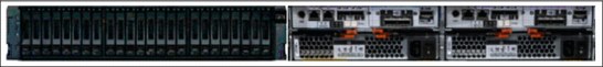
Figure 6-8 TS7740 Virtualization Engine Encryption Capable Cache Controller (front and rear views)
Figure 6-9 shows a diagram of the rear view, detailing the two separated controllers that are used for access redundancy and performance (Controller A and Controller B).

Figure 6-9 TS7740 Virtualization Engine Encryption Capable Cache Controller (rear view)
The TS7740 Virtualization Engine Encryption Capable Cache Controller provides
RAID 6-protected virtual volume disk storage. This storage temporarily holds data from the host before writing it to physical tape. It then caches the data to enable fast retrieval from
the disk.
RAID 6-protected virtual volume disk storage. This storage temporarily holds data from the host before writing it to physical tape. It then caches the data to enable fast retrieval from
the disk.
Beginning with R3.0 Licensed Internal Code, the CC9/CS9 controller supports FDE. All cache controllers and cache expansion drawers must be encryption capable to activate FDE. FDE encrypts the data at the hard disk level, covering most of data exposures and vulnerabilities with 256-bit data encryption to protect the data, which is approved by the US government for protecting secret-level classified data.
Data is protected through the hardware lifecycle, enabling return of defective disk drives for servicing with no exposure risks. FDE also does not affect performance because the encryption is hardware-based in the disk drive. The individual disk drive encryption engine matches the drive maximum port speed.
The individual disk drive encryption keys are protected and managed locally by the CC9/CS9 Cache Controller. Each FDE hard disk uses its own unique encryption key that is generated when the disk is manufactured, and regenerated when required by the IBM service personnel. This key is stored in an encrypted form within the FDE disk drive. It runs symmetric encryption and decryption of data at full disk speed with no effect on disk performance. This data encryption key never leaves the drive, so it is always secure.
There is a second key used by the FDE, named lock key or security key, which is a 32-byte random number that authenticates the drive with the CC9/CS9 Cache controller using asymmetric encryption for authentication. When the encryption is enabled in the TS7700 cache, each FDE drive must authenticate with the CC9/CS9 Cache controller. Otherwise, it does not return any data and remains locked. After the FDE disk drive has been authenticated, access to the drive operates like an decrypted drive.
One security key is created for all FDE drives attached to the CC9/CS9 cache controller and CX9/XS9 Cache Expansion drawers. The authentication key is generated, encrypted, and kept within the non-volatile storage RAM of the CC9/CS9 Cache Controller, in both Controller A and Controller B. Also, the TS7700 Virtualization Engine stores a third copy in the POWER7 persistent storage disks. A method is provided to securely export a copy to DVD when required.
The authentication typically occurs after the FDE has started, when it is in a locked state. If encryption was never enabled (meaning the lock key is not initially established between the CC9/CS9 Cache Controller and the hard disk), the disk is considered unlocked with unrestricted access like a non-FDE drive.
The TS7740 Virtualization Engine Cache Controller offers the following features:
•Two 8 Gbps Fibre Channel processor cards
•Two battery backup units (one for each processor card)
•Two power supplies with embedded enclosure cooling units
•Twenty-two DDMs, each possessing 600 GB of storage capacity, for a usable capacity of 9.45 TB
•Optional attachment to one or two TS7740 Virtualization Engine Encryption Capable Cache Drawers, Model 3956-CX9
TS7740 Virtualization Engine Cache Drawers (3956-CX9)
The TS7740 Virtualization Engine Encryption Capable Cache Drawer is a self-contained 2U enclosure that mounts in the 3952 Tape Frame.
Figure 6-10 shows the front view and the rear view of the TS7740 Virtualization Engine Encryption Capable Model CX9 Cache Drawer.

Figure 6-10 TS7740 Virtualization Engine Encryption Capable Cache Drawer (front and rear views)
The TS7740 Virtualization Engine Encryption Capable Cache Drawer expands the capacity of the TS7740 Virtualization Engine Cache Controller by providing extra RAID 6 disk storage. Each TS7740 Virtualization Engine Cache Drawer offers the following features:
•Two Fibre Channel processor cards
•Two power supplies with embedded enclosure cooling units
•22 DDMs, each with 600 GB of storage capacity, for a total usable capacity of 9.58 TB per drawer
•Attachment to the TS7740 Virtualization Engine Encryption Capable Cache Controller, Model 3956-CC9
TS7740 and TS7720T Virtualization Engine Tape Library attachments, drives, and media
In a TS7740 and TS7720T tape attach Virtualization Engine configuration, the TS7740 and TS7720T Virtualization Engine are used with an attached tape library. The TS7740 and TS7720T must have its own logical partition within the TS3500 Tape Library with dedicated tape drives and tape cartridges.
Tape libraries
The TS3500 Tape Library is the only library that is supported with TS7740 and TS7720T Virtualization Engine Release R3.2 Licensed Internal Code. To support a TS7740 or TS7720T, the TS3500 Tape Library must include a frame model L23 or D23 that is equipped with Fibre Channel switches.
The TS7740 Virtualization Engine Release 3.2 supports 4 Gb and 8 Gb Fibre Channel switches. Feature Code 4872 provides two TS7700 4 Gb Fibre Channel back-end switches. Feature Code 4875 provides only one 8 Gb Fibre Channel switch, so two features are required per TS7740 or TS7720T. Each TS7740 or TS7720T within a TS3500 library requires its own set of FC switches.
Tape drives
The TS7740 and TS7720T Virtualization Engine supports the following tape drives inside a TS3500 Tape Library:
•IBM 3592 Model J1A Tape Drive: However, for maximum benefit from the TS7740 Virtualization Engine, use more recent generations of the 3592 Tape Drive. The 3592 Model J1A Tape Drives cannot be intermixed with TS1130 Tape Drives or TS1140 Tape Drives. The 3592 Model J1A Tape Drives can be intermixed with TS1120 Tape Drives. If the TS1120s are intermixed, they must be set to J1A emulation mode.
•TS1120 Tape Drive (native mode or emulating 3592-J1A Tape Drives): Tape drive types cannot be intermixed except for 3592-J1A Tape Drives and TS1120 Tape Drives operating in 3592-J1A emulation mode.
•TS1130 Tape Drive: TS7740 Virtualization Engine Release 1.6 and later include support for TS1130 Tape Drives. When a TS1130 Tape Drive is attached to a TS7740 Virtualization Engine, all attached drives must be TS1130 Tape Drives. Intermixing is not supported by 3592-J1A and TS1120 Tape Drives. TS1130 Tape Drives can read data written by either of the previous generation 3592 Tape Drives. Tapes that are written in E05 format are appended to in E05 format. The first write to supported tapes is written in the E06 format.
If TS1130 Tape Drives are detected and other generation 3592 Tape Drives are also detected, the TS1130 Tape Drives are not configured.
•TS1140 Tape Drive (3592 Model E07) is the fourth generation of the 3592 Tape Drives. This encryption capable drive reads and writes in EFMT4 format, with 2176 tracks, using 32 read/write channels. The TS1120 and TS1130 have 16 read/write channels, and Model J1A has eight read/write channels.
All these advantages enable TS1140 to reach a 250 megabytes per second (MBps) of data transfer rate and 4 TB of native capacity on a JC cartridge. The E07 can read JA/JJ media written in J1A format (JA and JJ media are no longer supported with E07 drives) and E05 format. Also, 3592-E07 can read and write E06 format. No emulation mode is supported by the TS1140.
The TS1140 cannot be intermixed with any other model of the 3592 drives in the same TS7740.
The TS1140 attached to the TS7740 only supports JB, JC, and JK media for write.
Tapes are written in E07 format when writing from BOT or in E06 format when appending to a E06 format tape. Using Copy Export, you can specify either E06 or E07 formats for the output tape.
Tapes are written in E07 format when writing from BOT or in E06 format when appending to a E06 format tape. Using Copy Export, you can specify either E06 or E07 formats for the output tape.
If FC 9900 is installed, or if you plan to use tape drive encryption with the TS7740 or TS7720T Virtualization Engine, ensure that the installed tape drives support encryption and are enabled for System-Managed Encryption using the TS3500 Library Specialist. By default, TS1130 and TS1140 Tape Drives are encryption-capable. TS1120 Tape Drives with the encryption module are also encryption-capable. Encryption is not supported on 3592 Model J1A Tape Drives.
For more information, see 2.2.25, “Encryption of physical tapes” on page 50 and 4.4.8, “Planning for tape encryption in the TS7740 or TS7720 tape attach Virtualization Engine” on page 165.
Tape media
The TS7740 and TS7720T Virtualization Engine supports the following types of media:
•3592 Tape Cartridge (JA)
•3592 Expanded Capacity Cartridge (JB)
•3592 Advanced Tape Cartridge (JC)
•3592 Economy Tape Cartridge (JJ)
•3592 Economy Advanced Tape Cartridge (JK) media
Write Once Read Many (WORM) cartridges (JW, JR, JX, and JY) are not supported. Capacity scaling is not supported. The effect of capacity scaling is to contain data in a specified fraction of the tape. This yields faster locate and read times.
Not all media types are supported by all drive models. Check Table 6-1 for your configuration.
Table 6-1 Summary of the 3592 Tape Drive models and characteristics versus the supported media and capacity
|
3592 drive type
|
Supported media type
|
Encryption support
|
Capacity
|
Data rate
|
|
TS1140 Tape Drive
(3592-E07 Tape Drive)
|
JB
JC
JK
Media read only:
JA
JJ
|
Yes (IBM Security Key Lifecycle Manager (formerly IBM Tivoli Key Lifecycle Manager) or
IBM Security Key Lifecycle Manager for z/OS only)
|
1.6 TB (JB native)
4.0 TB (JC native)
500 GB (JK native)
4.0 TB (maximum all)
|
250 MBps
|
|
TS1130 Tape Drive
(3592-EU6 or 3592-E06 tape drive)
|
JA
JB
JJ
|
Yes
|
640 GB (JA native)
1.0 TB (JB native)
128 GB (JJ native)
1.0 TB (maximum all)
|
160 MBps
|
|
TS1120 Tape Drive
(3592-E05 Tape Drive)
|
JA
JB
JJ
|
Yes
|
500 GB (JA native)
700 GB (JB native)
100 GB (JJ native)
700 GB (maximum all)
|
100 MBps
|
|
3592-J1A
|
JA
JJ
|
No
|
300 GB (JA native)
60 GB (JJ native)
300 GB (maximum all)
|
40 MBps
|
The tape media has the following characteristics:
•Use of JB tape cartridges with TS1120 Tape Drives is supported only when operating in native capacity mode. Use of JB tape cartridges is supported by TS1130 Tape Drives.
•When TS1120 Tape Drives operating in native mode are replaced with TS1130 Tape Drives, more data written on the 3592-E05 formatted tapes is appended until they are full. As the active data on the E05 formatted tapes gets reclaimed or expired, the tape goes back to the scratch pool. On the next write, the tape will be reformatted to the 3592-E06 data format.
•TS1120 Tape Drives can operate in native E05 mode or in 3592-J1A emulation mode. However, all 3592 Tape Drives associated with the TS7700 Virtualization Engine must be TS1120 Tape Drives to operate in native E05 mode. To use TS1120 Tape Drives in native E05 mode, all attached drives must be set to E05 native mode. To use TS1120 Tape Drives in J1A emulation mode, all attached drives must be set to J1A emulation mode. The capacity of the tape media and performance is the same as the capacity and performance specified for a 3592-J1A.
•When 3592-J1A drives (or TS1120 Tape Drives in J1A emulation mode) are replaced with TS1130 Tape Drives, the TS7740 Virtualization Engine marks the J1A formatted tapes with a status of active data FULL. By marking these tapes full, the TS7740 Virtualization Engine does not append more data because the TS1130 Tape Drive cannot append data to a J1A formatted tape. As the active data on the J1A formatted tape gets reclaimed or expired, the tape goes back to the scratch pool. After the tape is in the scratch pool, it is reformatted to the E06 data format.
•When 3592-J1A drives (or TS1120 Tape Drives in J1A emulation mode) are replaced with TS1140 Tape Drives, the TS7740 Virtualization Engine marks the J1A formatted tapes with a status of active data FULL and SUNSET. By marking these tapes full, the TS7740 Virtualization Engine does not append more data because the TS1140 Tape Drive cannot append data to a J1A formatted tape. These tapes are ejected as soon as the data is reclaimed.
6.2 Hardware configurations
The minimum configurations and the optional enhancements for the TS7700 Virtualization Engine are described. The IBM TS7740, TS7720, and TS7720T Virtualization Engines
are covered.
are covered.
Tape library attachment
The current TS7740 and TS7720T Virtualization Engine no longer implements a physical Library Manager for its TS3500 attached tape library. All Enterprise Library Controller (ELC) functions and associated components are integrated into the TS7700 Virtualization Engine. The TS7720 Virtualization Engine is a disk-only solution and requires no physical tape library.
For more information about the TS3500 Tape Library, see the IBM System Storage TS3500 Tape Library Knowledge Center at:
TS7700 Virtualization Engine configuration summary
Release 3.2 hardware components and configuration requirements for a stand-alone cluster and for a multicluster grid configuration are described.
TS7740 (tape-attached) Virtualization Engine configuration summary
A TS7740 Virtualization Engine consists of the following components:
•One 3952 Tape Frame Model F05 containing:
– One TS7740 Virtualization Engine Server: An IBM System p server (3957 Model V07) with one 3.0 GHz eight-core processor card, 16 or 32 GB of 1066 MHz dynamic device reconfiguration 3 (DDR3) memory, and eight small form factor (SFF) hard disk drives (HDDs) with a redundant serial-attached SCSI (SAS) adapter.
– Two I/O expansion drawers. The I/O expansion drawers have independent power and cooling units. The TS7740 adapters (FICON host adapters, Grid Ethernet adapters, Tape FC Adapters and Cache Controller FC Adapters) are distributed evenly between the two separated enclosures for redundancy.
•Disk cache.
|
Remember: The TS7740 has featured different cache models and sizes since it was first launched. This summary lists Model CC9/CX9, which was introduced with TS7740 Release 3.0.
|
– One 3956 Model CC9 with up to two 3956 Model CX9s Cache Drawer with 600 GB HDDs (total of three drawers) providing up to 28.61 TB of data capacity. Considering a compression rate of 3:1, this represents 85.83 TB of uncompressed data.
•Two redundant network switches.
•Two redundant 4 or 8 Gb Fibre Channel (FC) switches in the TS3500 Tape Library that provide connectivity to the 3592 Model J1A, TS1120 Model E05, TS1130 Model E06/EU6, or TS1140 Model E07 tape drives.
•TS3000 Total Storage System Console (TSSC), local area network (LAN) hub, and keyboard/display: Can be considered optional if you already have an external TSSC.
TS7720 (disk-only) Virtualization Engine configuration summary
A TS7720 Virtualization Engine consists of the following components:
•One 3952 Tape Frame Model F05 containing:
– One TS7720 Virtualization Engine Server: An IBM System p server (3957 Model VEB) with one 3.0 GHz eight-core processor card, 16 or 32 GB of 1066 MHz dynamic device reconfiguration 3 (DDR3) memory, and eight SFF HDDs with a redundant SAS adapter.
•Two I/O expansion drawers: The I/O expansion drawers have independent power and cooling units. The TS7720 adapters (FICON host adapters, Grid Ethernet adapters, and Cache Controller FC Adapters for Base and Cache Expansion Frames) are distributed evenly between the two separated enclosures for redundancy. Two redundant network switches.
•TSSC, LAN hub, and keyboard/display: Can be considered optional if you already have an external TSSC.
•Disk cache.
|
Remember: The TS7720 has featured different cache models and sizes since it was first launched. This summary lists Model CS9/XS9, which was introduced with TS7720 Release 3.0.
|
• One 3956 Model CS9 configured with 3 TB SAS hard disk drives (HDDs) with up to nine 3956 Model XS9s (total of 10 drawers) for a maximum cache size of 239.86 TB of data capacity. Considering a compression rate of 3:1, this represents 719.58 TB of uncompressed data.
•Optional TS7720 Storage First Expansion Frame (3952-F05): One 3956 Model CS9s with up to 15 drawers of 3956 Model XS9s providing an extra capacity of 384 TB (24 TB per drawer) for a total maximum cache size of 623.86 TB. Considering a compression rate of 3:1, this represents 1871.58 TB of uncompressed data.
•Optional TS7720 Storage Second Expansion Frame (3952-F05): Release 3.1 introduced the capability to add a second CS9 based expansion frame with up to 15 drawers of 3956 Model XS9s (extra 24 - 384 TB) for a total maximum cache size of 1007.86 TB. Considering a compression rate of 3:1, this represents 3023.58 TB of uncompressed data.
|
Tip: The CS9-based second expansion frame can be attached to any CS9-based base frame and first expansion frame configuration. The TS7720 must be a 3957-VEB with R3.1 code or higher to support the CS9-based second expansion frame. A TS7720 Base Frame that contains 3956-CS7 or 3956-CS8 cache controllers but is not fully configured can add a TS7720 Storage Expansion Frame containing a 3956-CS9 cache controller and up to 15 3956-XS9 cache drawers.
|
In summary, all components are installed in an IBM 3952-F05 Tape Frame. The Virtualization Engine is connected to the host through FICON channels, with the tape library and disk cache connected through Fibre Channel adapters.
In a multicluster grid configuration, you can have up to six TS7700 Virtualization Engines, interconnected using two or four independent 1 Gb copper or optical grid Ethernet links (single-ported or dual-ported), or alternatively two 10 Gb longwave (LW) optical grid Ethernet links per TS7700 Virtualization Engine to interconnect the clusters.
A copper-based Ethernet network is the communications mechanism between the network switches, client network, TSSC, and virtualization engine.
TS7720T tape attach Virtualization Engine configuration summary
A TS7720T tape attached Virtualization Engine consists of the same components of a TS7720 disk-only Virtualization Engine. However, two of the existing Fibre Channel ports are used to communicate with the attached tape drives.
6.2.1 S7740 Virtualization Engine configuration details
The specific feature codes (FCs) of the TS7740 Virtualization Engine in a stand-alone and grid configuration are described for a minimum configuration.
TS7740 Virtualization Engine minimum configuration with R3.2
The minimum configuration of a TS7740 Virtualization Engine build with R3.2 machine code requires the following components (the FC number is in parenthesis):
•One 3952 Tape Frame Model F05 with the following required features:
– TS7740 Encryption Capable Base Frame (FC7330)
– Install 3957 V07 (FC5629)
– Plant Install 3956 CC9 (FC5652)
– Integrated Control Path (FC5758)
– Dual AC Power (FC1903)
– Two Ethernet switches
– Optionally, one TSSC
– Includes R3.2 Machine Code (FC9115)
– A power cord appropriate for the country of installation must be selected from features FC9954 through FC9959, or FC9966.
•One TS7740 Virtualization Engine Server (3957 Model V07) with the following required features:
– One of 1 TB Cache Enablement (FC5267)
– One of 100 MBps Increment (FC5268)
– Dual-port FC host bus adapter (FC5241)
– Mainframe Attach (FC9000)
– Includes R3.2 Machine Code (FC9115)
– Attach to TS3500 (FC9219)
– Plant Install in F05 (FC9350)
– Two of either 10 Gb Grid Optical LW Connection (FC1035), 1 Gb Grid Dual Port Copper Connection (FC1036), or 1 Gb Grid Dual Optical shortwave (SW) Connection (FC1037)
– Either two of host to Virtualization Engine FICON cables (FC0201 or FC0203) or one No Factory Cables (FC9700)
– FICON adapters (Two is the minimum configuration. The options are two or four FICON adapters) chosen from the following list:
• 8 Gb FICON Shortwave Attachment (FC3438) with one Memory upgrade (FC3462)
• 8 Gb FICON Longwave Attachment (FC3439) with one Memory Upgrade (FC3462)
• 4 Gb FICON Shortwave Attachment (FC3441)
• 4 Gb FICON Longwave Attachment (FC3442)
• 4 Gb FICON 10 km (6.2 miles) Longwave Attachment (FC3443)
– Console Attachment (FC2715)
•One TS7740 Cache Controller (3956 Model CC9) is required with the following required features:
– Plant Install in 3952-F05 Encryption Capable Controller (FC9352)
– 13.2 TB SAS Storage (FC7124)
•Two 4 Gb or 8 Gb Fibre Channel switches are required. Both switches must be the same type. Mixing one 4 Gb switch with one 8 Gb switch is not supported. TS7700 back-end SW Mounting Hardware (FC4871):
– Power Distribution Units (FC1950)
– One power cord FC9954 through FC9959 or FC9966
– Two new 8 Gb Fibre Channel switch (FC4875). The client might choose to reuse previously existing 4 Gb switches. In this case, check the appropriate Feature Codes to relocate switches from 3953 Model F05 to the 3584 Model L23 or D23. See the TS7700 3.2 Knowledge Center:
– Adjacent frame support for TS7700 back-end Fibre Channel switches (FC4874)
•One or more 3584 Model L23 or D23 frames with the following components:
– From four to sixteen 3592 tape drives: The TS7740 can be attached to 3592 Model J1A, TS1120 Model E05, TS1130 Model E06/EU6 tape drives, or TS1140 Model E07 Tape Drives. All attached drives must operate in the same mode. Intermixing is only supported for TS1120 Model E05 working in 3592-J1A emulation mode and 3592-J1A tape drives. The TS1140 Model E07 Tape drive cannot be intermixed with another drive type.
|
Tip: JA and JJ media are only supported for read-only operations by TS1140 Model E07 Tape Drives. Existing JA or JJ media will be marked read-only and moved to a Sunset category after reclamation, which enables the user to eject them later.
|
– Up to 16 FC 1515, 3592 Fibre Channel Tape Drive mounting kit.
6.2.2 TS7720 Virtualization Engine configuration details
The specific features of the TS7720 Virtualization Engine in the stand-alone and grid configurations are described for a minimum configuration.
TS7720 Virtualization Engine minimum configuration with R3.2
The minimum configuration of a TS7720 Virtualization Engine build with R3.2 machine code requires the components that are described here:
•One 3952 Tape Frame Model F05 with the following required features:
– TS7720 Virtualization Engine Encryption-Capable Base Frame (FC7331)
– Plant Install 3957 VEB (FC5627)
– Plant Install 3956 CS9 (FC5651)
– Integrated Control Path (FC5758)
– Dual AC Power (FC1903)
– Two Ethernet switches
– Optionally, one TSSC
– Includes R3.2 Machine Code (FC9115)
– A power cord appropriate for the country of installation must be selected from FC9954 through FC9959, or FC9966.
•One TS7720 Virtualization Engine Server (3957 Model VEB) with the following required features:
– 100 MBps Throughput - Plant (FC9268)
– Mainframe Attach (FC9000)
– Ship with R3.2 Machine Code (FC9115)
– Plant Install in 3952-F05 (FC9350)
– Two of either 10 Gb Grid Optical LW Connection (FC1035), 1 Gb Grid Dual Port Copper Connection (FC1036), or 1 Gb Grid Dual Optical SW Connection (FC1037)
– Either two of host to Virtualization Engine FICON cables (FC0201 or FC0203) or one No Factory Cables (FC9700)
– FICON adapters (Two is the minimum configuration. The options are two or four FICON adapters) chosen from the following list:
• 8 Gb FICON Shortwave Attachment (FC3438) with one Memory Upgrade (FC3462)
• 8 Gb FICON Longwave Attachment (FC3439) with one Memory Upgrade (FC3462)
• 4 Gb FICON Shortwave Attachment (FC3441)
• 4 Gb FICON Longwave Attachment (FC3442)
• 4 Gb FICON 10 km (6.2 miles) Longwave Attachment (FC3443)
– Console Attachment (FC2715)
•One TS7720 Cache Controller (3956 Model CS9) with the following required features:
– 36 TB SAS Storage (FC7115)
– Encryption (FC7404)
– Plant install in 3952-F05 Encryption Capable Controller (FC9352)
TS7720 Storage Expansion frame
One or two TS7720 Encryption Capable Expansion frame can be attached to an existing TS7720 base frame or a TS7720 base frame plus First TS7720 Expansion frame (CS7/CS8) models. For the CS7/CS8 models, there is no requirement for the existing base or expansion frame to be fully configured, as the upgrades for those models have been withdrawn.
The CS9/XS9 base frame must contain one CS9 cache controller and nine XS9 cache drawers (fully configured) before the first expansion frame can be added. Likewise, A CS9 first expansion frame must be fully configured (CS9 plus 15 XS9) before the second expansion frame can be added.
The following configurations are based on the new cache models CS9/XS9:
•On a TS7720 encryption capable base frame (3952 Tape Frame Model F05 with FC7331, the following features are required in addition to the minimum configuration and optional requirements defined previously:
– TS7720 Encryption-capable Expansion Frame Attach (FC7323) for each expansion frame attached
– Nine 3956-XS9 units - either FC5655 Plant-installed, FC5656 Field-installed cache drawers, or a mix of both
•One or two 3952 Tape Frame Model F05 TS7720 Storage Expansions with the following required features:
– TS7720 Encryption Capable Expansion Frame (FC 7332)
– One of plant-installed 3956-CS9 (FC 5651)
– Zero to fifteen plant-installed 3956-XS9 (FC5655) or
– Zero to fifteen field-installed 3956-XS9 (FC5656) or
– A mix of both up to a maximum of fifteen instances.
– Dual AC Power (FC1903)
– A power cord appropriate for the country of installation must be selected from FC9954 through FC9959, or FC9966
There are many other possible TS7720 Cache configurations, mixing different cache models and disk module sizes. The previous topic focused on new configurations featuring Model CS9/XS9, which was introduced with TS7720 Release 3.0. For more information about cache models and available upgrade configurations, see the IBM Knowledge Center:
6.2.3 TS7720T Virtualization Engine configuration details
The specific features of the TS7720T Virtualization Engine in the stand-alone and grid configurations are the same as the TS7720. The TS7720T is an upgrade to the TS7720.
There are specific feature codes associated with the TS7720T:
•FC #5273 Enable TS7720 tape attach
– Can be enabled on any TS7720 VEB except a three-frame TS7720 with a CS8-based expansion frame.
•FC #5274 1TB Active premigration capacity
– A minimum quantity of 1 is required.
– A maximum quantity of 10 is allowed.
•FC #9219 TS3500 Attach
– TS7720T has the same requirements as TS7740 for two FC switches and 4 - 16 3592 tape drives.
•FC #9900 Tape encryption enablement (optional feature)
– Independent from disk-based encryption. You might enable either one separately or both together.
6.2.4 TS3000 System Console (TSSC)
The TS300 System Console connects to multiple Enterprise Tape Subsystems, including TS3500 Tape Libraries, 3953 L05 Library Managers, 3592 Controllers, 3494 Library Managers, 3494 Virtual Tape Servers (VTS), 3494 Virtual Tape Controllers (VTC), and TS7700 Virtualization Engine.
All of these devices are connected to a dedicated, private local area network that is owned by TSSC. Remote data monitoring of each one of these subsystems is provided for early detection of unusual conditions. The TSSC sends this summary information to IBM if something unusual is detected and the Call Home function has been enabled.
|
Requirement: Connection to the TS3000 System Console is required with an IBM TS7700 Virtualization Engine.
|
For the R3.2 IBM TS7700 Virtualization Engine (3957 Models VEA/VEB), the following features are available for installation:
– FC #2704 TS3000 System Console expansion 26-port Ethernet switch/rackmount: This provides a 26-port Ethernet switch and attachment cable for connection to an IBM System Storage TS3000 System Console (TSSC). Up to 24 more connections are provided by this feature for connection of TSSC FC 2714, 2715, or another FC 2704.
– FC #2714 Console Expansion: This feature provides an attachment cable, rack-mountable Ethernet switch, and associated mounting hardware to attach the TS7700 to an existing external TS3000 System Console (features #2720, #2721, #2722, #2730, or #2732) or IBM TotalStorage Master Console for Service (feature #2718). Use this feature when an extra Ethernet switch is required.
– FC #2715 Console Attachment: This feature provides a cable to attach the TS7700 to an Ethernet hub provided by an existing TS3000 System Console (features #2720, #2721, #2722, #2730, or #2732), IBM TotalStorage Master Console for Service (feature #2718), or Console Expansion (#2714). Use this feature when an extra Ethernet hub is not required.
– FC #2725 Rackmount TS3000 System Console: This feature provides the current TSSC 1 U form factor server released in R3.2 Feature codes #2704 and #5512 are still required. Call Home and remote support are now done with broadband. A modem option is not available.
– FC #2748 Optical drive: This feature released in R3.2 is required.
6.2.5 Cables
The cable feature codes for attachment to the TS7700 Virtualization Engine and extra cables, fabric components, and cabling solutions are described.
Required cable feature codes
The following cable feature codes are needed for attachment to the TS7700 Virtualization Engine.
A TS7700 Virtualization Engine Server with the FICON Attachment features (FC3441, FC3442, FC3443, FC3438, or FC3439) can attach to FICON channels of IBM System z mainframe, IBM zSeries server, or IBM S/390® server using FICON cable features ordered on the TS7700 Virtualization Engine Server. A maximum of eight FICON cables, each 31 meters in length, can be ordered.
One cable must be ordered for each host system attachment by using the following cable features:
•FC3442 and FC3443, 4 Gb FICON Long-Wavelength Attachment feature: The FICON long wavelength adapter included with FC3442 (4 Gb FICON Long-Wavelength Attachment) or FC3443 (4 Gb FICON 10 kilometer (km) Long-Wavelength Attachment) has an LC Duplex connector. It can connect to FICON long wavelength channels of IBM z™ Enterprise, IBM System z9®, IBM System z10®, and S/390 servers using a 9-micron single-mode fiber cable.
The maximum fiber cable length is 4 KM (2.48 miles) for FC3442 and 10 KM (6.2 miles) for FC3443. If standard host attachment cables (31 m) are required, they can be specified with FC0201 - 9-micron LC/LC 31-meter fiber cable or FC 0203, 50 micron LC/LC 31-meter fiber cable.
•FC3441, 4 Gb FICON Short-Wavelength Attachment feature: The FICON short wave-length adapter included with FC3441 has an LC Duplex connector. It can connect to FICON short wavelength channels of z Enterprise, System z9, System z10, and S/390 servers using a 50-micron or 62.5-micron multimode fiber cable. At 4 Gbps, the maximum fiber cable length allowed by 50-micron cable is 150 m, or 55 m if using 62.5-micron cable.
If standard host attachment cables are required, they can be specified with FC 0203 - 50 Micron LC/LC 31-meter fiber cable and FC 3438, 8 Gb FICON Short Wavelength Attachment.
|
Requirement: 8 Gb FICON adapters require FC 3462 (16 GB memory upgrade) and TS7700 Licensed Internal Code R3.1 or later.
|
•Wavelength Attachment provides one short-wavelength FICON adapter with an LC Duplex connector for attachment to a FICON host system shortwave channel using a 50 micron or 62.5-micron multimode fiber cable. Each FICON attachment can support up to 512 logical channels. At 8 Gbps speed, the total cable length cannot exceed the following lengths:
– 150 meters using 50-micron OM3 (2000 MHz*km) Aqua blue-colored fiber
– 50 meters using 50-micron OM2 (500 MHz*km) Orange-colored fiber
– 21 meters using 62.5-micron OM1 (200 MHz*km) Orange-colored fiber
If standard host attachment cables are required, they can be specified with FC 0201, 9-micron LC/LC 31-meter fiber cable or FC 0203, 50-micron LC/LC 31-meter fiber cable.
•FC 3439, 8 Gb FICON Long Wavelength Attachment, provides one long-wavelength FICON adapter, with an LC Duplex connector, for the attachment to a FICON host system long wave channel using a 9-micron single-mode fiber cable. The total cable length cannot exceed 10 km. Each FICON attachment can support up to 512 logical channels.
If standard host attachment cables are required, they can be specified with FC 0201, 9-micron LC/LC 31-meter fiber cable or FC 0203, 50 micron LC/LC 31-meter fiber cable.
|
Requirement: FC 3401 (Enable 8 Gb FICON dual port) enables the second port on each installed 8 Gb FICON adapter. With FC3401, two instances of FC0201 or FC0203 are required for each FC 3438 or FC3439.
|
Extra cables, fabric components, and cabling solutions
Conversion cables from SC Duplex to LC Duplex are available as features on the System z servers if you are currently using cables with SC Duplex connectors that now require attachment to fiber components with LC Duplex connections. Extra cable options, along with product support services, such as installation, are offered by IBM Global Services Networking Services. See the IBM Virtualization Engine TS7700 Introduction and Planning Guide, GA32-0568, for Fibre Channel cable planning information.
If Grid Enablement (FC4015) is ordered, Ethernet cables are required for the copper/optical 1 Gbps and optical longwave adapters to attach to the communication grid.
6.3 TS7700 Virtualization Engine component upgrades
Several field-installable upgrades give an existing TS7700 Virtualization Engine more functions or capacities. This section reviews the TS7700 Virtualization Engine component
FC upgrades.
FC upgrades.
6.3.1 TS7700 Virtualization Engine concurrent system component upgrades
Concurrent system upgrades can be installed while the TS7700 Virtualization Engine is online and operating. The following component upgrades can be made concurrently to an existing, onsite TS7700 Virtualization Engine:
•Enable tape attach on TS7720 Virtualization Engine with R3.2 or higher installed. Use FC 5273, which is mandatory for TS7720T.
•1 TB Active premigration policy: 1 minimum to 10 maximum. Use FC 5274, which is mandatory for TS7720T.
•TS3500 attach for TS7720T. Same requirements as TS7740 for 2 FC switches and 4 - 16 3592 drives. Use FC 9219, which is mandatory for TS7720T.
•Incremental disk cache capacity enablement (TS7740 Virtualization Engine only).
You can add a 1 TB (0.91 tebibytes (TiB)) increment of disk cache to store virtual volumes, up to 28 TB (25.46 TiB). Use FC 5267, 1 TB cache enablement to achieve this upgrade.
•Enable 8 Gb FICON second port. Use FC 3401.
•Incremental data throughput.
You can add 100 mebibytes per second (MiBps) increments of peak data throughput up to your system’s hardware capacity by using FC5268.The throughput is considered as transferred from a host to a virtualization node (vnode) before compression.
Model VEB: A maximum of nine instances of FC5268 can be ordered, plus one Plant Installed FC9268, for a total of ten 100 MiB/sec instances, when using 4 Gb FICON adapters. With 4 Gb FICON adapter installed and 10 instances of 100 MBps throughput increments installed, the host throughput is not constrained at 1000 MBps.
Model V07: A maximum of 10 instances of FC5268 can be ordered for a total of ten
100 MiB/sec instances. When using 4 Gb FICON adapters (with 4 Gb FICON adapter installed and 10 instances of 100 MBps throughput increments installed, the host throughput is not constrained at 1000 MBps.
100 MiB/sec instances. When using 4 Gb FICON adapters (with 4 Gb FICON adapter installed and 10 instances of 100 MBps throughput increments installed, the host throughput is not constrained at 1000 MBps.
With the additional bandwidth and connectivity offered by new 8 Gb FICON adapters, the maximum number of 100 MBps throughput increments is increased. Up to 25 total throughput increments can be installed on any server with 8 Gb FICON adapters.
Host throughput on TS7700 clusters with 25 increments installed are not constrained at 2500 MBps.
•Selective Device Access Control.
You can grant exclusive access to one or more logical volume ranges by only certain logical control units (LCUs) or subsystem IDs within a composite library for host-initiated mounts, ejects, and changes to attributes or categories. Use FC5271, Selective Device Access Control (SDAC), to add this upgrade.
Each instance of this feature enables the definition of eight selective device access groups. The default group provides a single access group, resulting in nine total possible access groups. This feature is available only with a microcode level of 8.20.0.xx or higher.
|
Restriction: The feature must be installed on all clusters in the grid before the function becomes enabled.
|
•Increased logical volumes.
The default number of logical volumes supported is 1,000,000. You can add support for extra logical volumes in 200,000 volume increments using FC5270. Up to a total of 4,000,000 logical volumes are supported by the maximum quantity of 15 FC5270s installed with the 3957-VEB and 3957-V07.
|
Remember: The number of logical volumes supported in a grid is set by the cluster with the smallest number of FC5270 increments installed.
When joining a cluster to an existing grid, the joining cluster must meet or exceed the currently supported number of logical volumes of the existing grid.
When merging one or more clusters into an existing grid, all clusters in the ending grid configuration must contain enough FC5270 increments to accommodate the sum of all post-merged volumes.
|
•Dual-port grid connection.
You can enable the second port of each dual port, 1 Gbps grid connection adapter for a total of four 1-Gbps grid Ethernet connections in the following TS7700 server configurations:
– On a new 3957-V07 or 3957-VEB when FC1036, 1 Gbps grid dual port copper connection, or FC1037, 1 Gbps dual port optical shortwave connection, is present.
Use FC1034, Enable dual port grid connection, to achieve this upgrade.
•Tape Encryption Enablement (TS7740 and TS7720T Virtualization Engine only).
With TS1130 and TS1140 tape drives installed, implementing encryption is nondisruptive. Use FC9900, Encryption Enablement, to achieve this upgrade.
•Disk encryption.
You can encrypt the disk drive modules (DDMs) within a TS7700 Virtualization Engine disk storage system.
•TS7720 Storage Expansion frame.
You can add up to two cache expansion frames to a fully configured TS7720 Virtualization Engine using FC 9323 Expansion frame attachment, and apply FC 7323, TS7720 Storage expansion frame to a 3952 F05 Tape Frame.
For cache upgrade requirements and configurations, see 6.3.3, “TS7720 Virtualization Engine Cache upgrade options” on page 227.
|
Note: The adapter installation (FC5241) is non-concurrent.
|
6.3.2 TS7700 Virtualization Engine non-concurrent system component upgrades
A multicluster GRID configuration can enable practically all changes or upgrades to be concurrent from a client’s standpoint, putting one individual member in service at a time. In a stand-alone cluster configuration, non-concurrent upgrades require the TS7700 Virtualization Engine to be brought offline before installation. In certain instances, the targeted component must be reconfigured before the upgrade takes effect. The component upgrades listed in the following sections must be made non-concurrently to an existing, onsite TS7700 Virtualization Engine:
•8 Gb FICON adapters
You can install up to two 8 Gb FICON adapters or exchange adapters for another type (SW-to-LW or LW-to-SW) to connect a TS7700 Server (3957-V07 or 3957-VEB) to a host system. FICON adapter replacement is non-concurrent when used with a 3957-V07 or 3957-VEB. Use FC 3438, 8 Gb FICON Short Wavelength Attachment, or FC 3439, 8 Gb FICON Long Wavelength Attachment for this installation. You can also use FC 3401, Enable 8 Gb FICON dual port to enable a second 8 Gb FICON adapter port for double the number of host connections. The enablement of the second port is concurrent.
•4 Gb FICON adapters
You can install Fibre Channel (FICON) adapters to convert a two FICON configuration to a four FICON configuration, or to replace one pair of FICON adapters of a certain type with a pair of another type for shortwave (4 km (2.48 miles)) or longwave (10 km (6.2 miles)). Replacement of an existing FICON adapter requires the removal of the original feature and addition of the new feature. Use FC3441, FICON short-wavelength attachment; FC3442, FICON long-wavelength attachment; and FC3443, FICON 10-km long-wavelength attachment for these upgrades.
•Ethernet adapters for grid communication:
– Shortwave fiber Ethernet
You can add a 1 Gbps shortwave fiber Ethernet adapter for grid communication between TS7700 Virtualization Engines. On a 3957-V07 or 3957-VEB, use FC1037, 1 Gbps dual port optical shortwave connection, for this upgrade.
– Longwave fiber Ethernet
On a 3957-V07 or 3957-VEB, you can add a longwave fiber Ethernet adapter for grid communication between TS7700 Virtualization Engines. Use FC1035, Grid optical longwave connection, for this upgrade.
FC 1035, 10 Gb grid optical LW connection, provides a single port, 10 Gbps Ethernet longwave adapter for grid communication between TS7700 Virtualization Engines. This adapter has an LC Duplex connector for attaching 9 micron, single mode fiber cable. This is a standard longwave (1,310 nm) adapter that conforms to the IEEE 802.3ae standards. It supports distances up to 10 km (6.2 miles). This feature is only supported on a 3957-V07 or 3957-VEB operating a microcode level of 8.20.0.xx or later.
|
Restriction: These adapters cannot negotiate down to run at 1 Gb. They must be connected to a 10 Gb network device or light point.
|
– Copper Ethernet
You can add a 1 Gbps copper Ethernet adapter for grid communication between TS7700 Virtualization Engines. On a 3957-V07 or 3957-VEB, use FC1036, 1 Gbps grid dual port copper connection, to achieve this upgrade.
|
Clarification: On a TS7700 Virtualization Engine, you can have two 1 Gbps copper Ethernet adapters or two 1 Gbps shortwave fiber Ethernet adapters or two
10 Gbps longwave fiber Ethernet adapters (3957-V07 and VEB only) installed. Intermixing different types of Ethernet adapters within one cluster is not supported. |
– TS7700 Server dual copper/optical Ethernet Adapter Card Conversion
You can convert a dual port grid Ethernet adapter in a TS7700 Server for a dual port adapter of the opposite type, by ordering FC 1036 (dual port copper) in exchange for a dual port optical Ethernet adapter FC1037, or vice-versa.
In a similar way, you can order the 10 Gb grid longwave adapter (FC1035) in exchange for the 1 Gbps adapters (FC1036 and FC1037) and vice versa.
With release 3.1, 8 Gb FICON host bus adapters (HBAs) are available for the 3957-V07 and 3957-VEB. New builds contain the 8 Gb FICON cards. When the 8 Gb FICON HBAs are ordered, an extra 16 GB of memory is required, bringing the total memory to 32 GB. The additional 16 GB of memory is supplied by FC3462.
•TS7720 Server Fibre Channel host bus adapter installation
You can install two Fibre Channel interface cards in theTS7720 Server (3957-VEB) to connect the TS7720 Server to the disk arrays in the TS7720 Storage Expansion Frame. Use FC 5241, Dual port FC HBA to achieve this installation.
•FC4743 and FC5629 (Remove 3957-V06/VEA and Install 3957-V07/VEB)
This is support to upgrade your existing TS7700 Virtualization Engine equipped with the previous 3957-V06/VEA server to the newer 3957-V07/VEB that is based on IBM POWER7 technology.
•TS7740 to TS7740 frame replacement
This is available only for the TS7740 Virtualization Engine. The goal is to replace the entire TS7740 frame with a 3957-V06 server by a new TS7740 with a 3957-V07 server from manufacturing, due to technical reasons. For example, a new cache model is wanted or a lease contract is expiring.
6.3.3 TS7720 Virtualization Engine Cache upgrade options
This section describes the Tape Volume Cache (TVC) upgrade options that are available for the TS7720 Virtualization Engine. If you want to implement encryption, see the feature codes in Appendix A, “Feature codes and RPQ” on page 797.
For the data storage values in TB versus TiB, see 1.5, “Data storage values” on page 12.
TS7720 existing frame operating with a 3956-CS9 controller
You can use FC 5656, Field installation of 3956-XS9, as an MES to add up to a maximum of nine TS7720 Cache Drawers to an existing TS7720 Cache subsystem operating with a 3956-CS9 controller.
Table 6-2 shows the resulting usable capacity associated with each upgrade configuration available to an existing TS7720 Cache base frame.
The CS9-based first expansion frame can be attached to any CS9-based base frame configuration. A CS9 base frame must be filled before the first expansion frame can be added.
Table 6-2 Upgrade configurations for an existing TS7720 Cache
|
Existing minimum TS7720 Cache configuration
|
Extra TS7720 Cache Drawer(s) (instances of FC 5656, Field installation of 3956-XS9)
|
Total count of TS7720 Cache units
|
Usable capacity
|
|
1 TS7720 Cache Controller (3956-CS9)
|
1
|
2
|
45.56 TB (41.44 TiB)
|
|
2
|
3
|
68.34 TB (62.15 TiB)
|
|
|
3
|
4
|
91.12 TB (82.87 TiB)
|
|
|
4
|
5
|
113.9 TB (103.6 TiB)
|
|
|
5
|
6
|
136.68 TB (124.31 TiB)
|
|
|
6
|
7
|
159.46 TB (145.03 TiB)
|
|
|
7
|
8
|
182.24 TB (165.75 TiB)
|
|
|
8
|
9
|
205.02 TB (186.46 TiB)
|
|
|
9
|
10
|
227.8 TB (207.18 TiB)
|
Release 3.1 introduced the capability to add a second CS9-based expansion frame that contains a single 3956-CS9 cache controller and up to 15 3956-XS9 cache expansion drawers. This provides an extra 24 - 384 TB of disk cache. The CS9-based second expansion frame can be attached to any CS9-based base and first expansion frame configuration. A CS9 first expansion frame must be filled before the second expansion frame can be added.
You can use FC 7323, TS7720 Storage expansion frame, as an MES to add up to two expansion frames to a fully configured TS7720 Cache subsystem operating with a 3956-CS9 controller. Each TS7720 Storage Expansion Frame contains one extra cache controller, controlling up to 15 extra expansion drawers.
Table 6-3 shows the resulting usable capacity associated with each upgrade configuration.
Table 6-3 TS7720 Storage Expansion Frame configurations
|
Cache configuration in a new TS7720 Virtualization Engine
|
Cache units1 in eachTS7720 Storage Expansion Frame cache controller (3956-CS9) plus optional cache drawers (3956-XS9)
|
First TS7720 Storage Expansion Frame
|
Second TS7720 Storage Expansion Frame
|
||
|
Total cache units (including TS7720 Base Frame)
|
Available capacity
|
Total cache units (including TS7720 Base Frame)
|
Available capacity
|
||
|
1 TS7720 Cache Controller (3956-CS9)
9 TS7720 Cache Drawers (3956-XS9)
|
1 (controller only)
|
11
|
263.86 TB (262.79 TiB)
|
27
|
647.86 TB (646.79 TiB)
|
|
2
|
12
|
287.86 TB (286.79 TiB)
|
28
|
671.86 TB (670.79 TiB)
|
|
|
3
|
13
|
311.86 TB (310.79 TiB)
|
29
|
695.86 TB (694.79 TiB)
|
|
|
4
|
14
|
335.86 TB (334.79 TiB)
|
30
|
719.86 TB (718.79 TiB)
|
|
|
5
|
15
|
359.86 TB (358.79 TiB)
|
31
|
743.86 TB (742.79 TiB)
|
|
|
6
|
16
|
383.86 TB (382.79 TiB)
|
32
|
767.86 TB (766.79 TiB)
|
|
|
7
|
17
|
407.86 TB (406.79 TiB)
|
33
|
791.86 TB (790.79 TiB)
|
|
|
8
|
18
|
431.86 TB (430.79 TiB)
|
34
|
815.86 TB (814.79 TiB)
|
|
|
9
|
19
|
455.86 TB (454.79 TiB)
|
35
|
839.86 TB (838.79 TiB)
|
|
|
10
|
20
|
479.86 TB (478.79 TiB)
|
36
|
863.86 TB (862.79 TiB)
|
|
|
11
|
21
|
503.86 TB (502.79 TiB)
|
37
|
887.86 TB (886.79 TiB)
|
|
|
12
|
22
|
527.86 TB (526.79 TiB)
|
38
|
911.86 TB (910.79 TiB)
|
|
|
13
|
23
|
551.86 TB (550.79 TiB)
|
39
|
935.86 TB (934.79 TiB)
|
|
|
14
|
24
|
575.86 TB (574.79 TiB)
|
40
|
959.86 TB (958.79 TiB)
|
|
|
15
|
25
|
599.86 TB (598.79 TiB)
|
41
|
983.86 TB (982.79 TiB)
|
|
|
16
|
26
|
623.86 TB (622.79 TiB)
|
42
|
1007.86 TB (1006.79 TiB)
|
|
1 The term “Total cache units” refers to the combination of cache controllers and cache drawers.
Figure 6-11 shows the maximum TS7720 CS9-based cache configuration with two expansion frames installed.
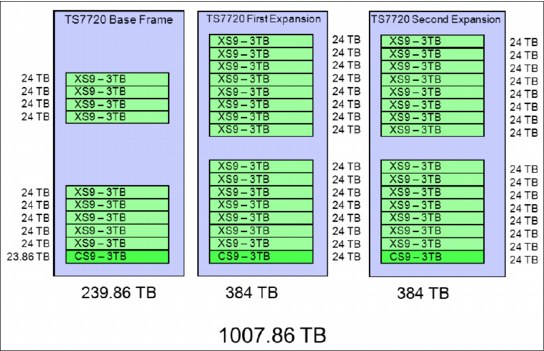
Figure 6-11 TS7720 with CS9/XS9 Cache
TS7720 existing frame operating with a 3956-CS7/CS8 controller
An expansion frame can be added to an existing TS7720 base frame that contains previous generations of disk cache. A TS7720 base frame with either 40 TB or 70 TB of CS7/XS7 based cache can increase its cache by adding one or two CS9/XS9 expansion frames.
The expansion frames are configured with one CS9 cache controller and 0 - 15 XS9 cache drawers each. The expansion frames add 24 - 384 TB of storage each. There is no need to fully populate the base frame with XS7 cache drawers before adding the CS9/XS9 based expansion frames.
The CS9/XS9 based disk cache in the first expansion frame must be fully populated before adding a second cache expansion frame.
Figure 6-12 on page 231 shows TS7720 CS9/XS9 Expansion Frames with 40 TB/70 TB CS7 based Cache in Base Frame.

Figure 6-12 TS7720 CS9/XS9 Expansion Frames with 40 TB/70 TB CS7-based Cache in Base Frame
A TS7720 base frame with a CS7 cache controller, three XS7 cache drawers with 1 TB drives, and one to three XS7 cache drawers with 2 TB drives, can increase its cache by adding one or two CS9/XS9 expansion frames. The expansion frames are configured with one CS9 cache controller and 0 - 15 XS9 cache drawers each. The expansion frame adds 24 - 384 TB of storage each.
A TS7720 base frame with a CS7 cache controller and zero to six XS7 cache drawers with 2 TB drives can increase its cache by adding one or two CS9/XS9 expansion frames. The expansion frames are configured with one CS9 cache controller and 0 - 15 XS9 cache drawers each. The expansion frame adds 24 - 384 TB of storage each.
There is no need to fully populate the base frame with XS7 cache drawers before adding the CS9/XS9 based expansion frame.
The CS9/XS9 based disk cache in the first expansion frame requires release 3.0 or later. The addition of the second CS9/XS9 based expansion frame requires release 3.1 or later.
Figure 6-13 on page 233 shows CS9/XS9 Expansion Frames with CS8 and mixed XS7-based Cache in Base Frame.
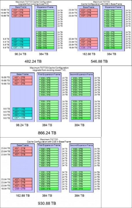
Figure 6-13 CS9/XS9 Expansion Frames with CS8 and mixed XS7-based Cache in Base Frame
A CS9-based second expansion frame can be added to an existing TS7720 base frame and expansion frame that contains previous generations of disk cache. The CS9-based second expansion frame is configured with one CS9 cache controller and 0 - 15 XS9 cache drawers each. The second expansion frame adds 24 - 384 TB of storage each.
There is no need to fully populate the expansion frame with XS7 cache drawers before adding the CS9/XS9 based second expansion frame.
Figure 6-14 shows CS9-based Second Expansion Frame with 40 TB CS7-based Cache in Base Frame and 278 TB CS8-based Cache in First Expansion Frame.
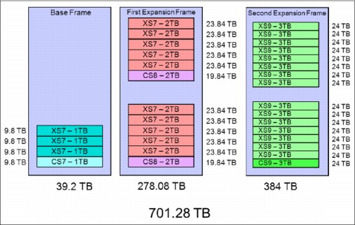
Figure 6-14 CS9-based Second Expansion Frame with 40 TB CS7-based Cache in Base Frame and 278 TB CS8-based Cache in First Expansion Frame
Figure 6-15 shows a CS9-based Second Expansion Frame with 70 TB CS7-based Cache in a Base Frame and 278 TB CS8-based Cache in a First Expansion Frame.
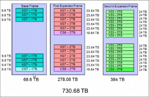
Figure 6-15 CS9 based Second Expansion Frame with 70 TB CS7 based Cache in Base Frame and 278 TB CS8 based Cache in First Expansion Frame
Figure 6-16 shows a CS9-based Second Expansion Frame with 98 TB CS7-based Cache in a Base Frame and 278 TB CS8-based Cache in a First Expansion Frame.

Figure 6-16 CS9-based Second Expansion Frame with 98 TB CS7-based Cache in Base Frame and 278 TB CS8-based Cache in First Expansion Frame
Figure 6-17 shows a CS9-based Second Expansion Frame with 163 TB CS8-based Cache in a Base Frame and 278 TB CS8-based Cache in a First Expansion Frame.

Figure 6-17 CS9-based Second Expansion Frame with 163 TB CS8-based Cache in Base Frame and 278 TB CS8-based Cache in First Expansion Frame
6.3.4 TS7740 Virtualization Engine Cache upgrade options
This section describes the TVC upgrade options that are available for the TS7740 Virtualization Engine. If you want to introduce encryption, see the feature codes in Appendix A, “Feature codes and RPQ” on page 797. Incremental features help tailor storage costs and solutions to your specific data requirements.
Subsets of total cache and peak data throughput capacity are available through incremental features FC5267, 1 TB cache enablement, and FC5268, 100 MiBps increment. These features enable a wide range of factory-installed configurations and enable you to enhance and update an existing system.
They can help you meet specific data storage requirements by increasing cache and peak data throughput capability to the limits of your installed hardware. Increments of cache and peak data throughput can be ordered and installed concurrently on an existing system through the TS7740 Virtualization Engine MI.
Incremental disk cache capacity enablement
Incremental disk cache capacity enablement is available in 1 TB (0.91 TiB) increments in a TS7740 cluster. Disk cache is used for these types of data:
•Data originated by a host through the vnodes of a local or remote cluster
•Data recalled from a physical tape drive associated with the cluster
•Data copied from another cluster
The capacity of the system is limited to the number of installed 1 TB increments, but the data stored is evenly distributed among all physically installed disk cache. Therefore, larger drawer configurations provide improved cache performance even when usable capacity is limited by the 1 TB installed increments. Extra cache can be installed up to the maximum capacity of the installed hardware.
The following tables display the maximum physical capacity of the TS7740 Cache configurations and the instances of FC5267, 1 TB cache enablement, required to achieve each maximum capacity. Perform the installation of cache increments through the TS7740 Virtualization Engine MI.
|
Considerations:
•A minimum of one instance of FC5267, 1 TB cache enablement, can be ordered on the TS7740 Cache Controller, and the required amount of disk cache capacity is 1 TB.
•Enough physical cache must be installed before adding extra 1-TB cache increments.
•Cache Increments become active within 30 minutes.
•FC5267, 1 TB Cache Enablement, is not removable after activation.
|
Table 6-4 shows the maximum physical capacity of the TS7740 Cache configurations using the 3956-CC9 cache controller.
Table 6-4 Supported TS7740 Cache configurations using the 3956-CC9 cache controller
|
Configuration
|
Physical capacity
|
Maximum usable capacity
|
Maximum quantity of FC52671
|
|
1 TS7740 Cache Controller (3956-CC9)
|
9.6 TB
|
9.45 TB (8.59 TiB)
|
10
|
|
1 TS7740 Cache Controller (3956-CC9)
1 TS7740 Cache Drawer (3956-CX9)
|
19.2 TB
|
19.03 TB (17.30 TiB)
|
19
|
|
1 TS7740 Cache Controller (3956-CC9)
2 TS7740 Cache Drawer (3956-CX9)
|
28.8 TB
|
28.60 TB (26.02 TiB)
|
28
|
1 Number of instances required to use maximum physical capacity.
6.4 TS7700 Virtualization Engine upgrade to Release 3.2
The R3.2 release of code can be installed on any previous V07 or VEB-based TS7700 system that contains a code level of R2.1 or R3.0. Existing V06 and VEA systems do not support R3.1 or higher levels of microcode.
6.4.1 Planning for the upgrade
A multicluster GRID configuration can enable practically all changes or upgrades to be concurrent from a client’s standpoint, putting one individual member in service at a time. The Release 3.2 Licensed Internal Code upgrade is a disruptive activity in a stand-alone cluster. A Licensed Internal Code update is done by an IBM service support representative (SSR). Preinstallation planning and a scheduled outage are necessary.
When updating code on a cluster in a grid configuration, planning an upgrade to minimize the time that a grid operates clusters at different code levels is important.
Before starting a code upgrade, all devices in this cluster must be quiesced and varied offline. A cluster in a grid environment must be put into service mode and then varied offline for the code update. You might consider opening more devices from other clusters in the grid because you are losing devices for the code upgrade.
|
Restriction: Within the grid, some new functions or features are not usable until all clusters within the grid are updated to the same Licensed Internal Code (LIC) level and feature codes.
The MI in the cluster being updated is not accessible during installation. You can use a web browser to access the remaining clusters, if necessary.
|
Apply the required software support before you perform the Licensed Internal Code upgrade.
|
Important: Ensure that you check the D/T3957 Preventive Service Planning (PSP) bucket for any recommended maintenance before performing the LIC upgrade.
PSP buckets are at the following address. Search for D/T3957:
|
6.5 Adding clusters to a grid
The TS7700 Virtualization Engine clusters can be installed in stand-alone or multicluster grid configurations. This section describes the available options and the required steps to add a cluster to a grid, merge a cluster into a grid, or merge a grid with another grid. Adding clusters to a grid is a concurrent process from the client’s standpoint. None of the existing clusters must go into service when joining a new cluster to the grid.
6.5.1 TS7700 Virtualization Engine grid upgrade concept
A TS7700 Virtualization Engine Grid refers to two, three, four, five, or six TS7700 Virtualization Engine clusters that can be physically separated and are interconnected by using a Internet Protocol network.
Migrations to a TS7700 Virtualization Engine multicluster grid configuration require the use of the Internet Protocol network. In a two-cluster grid, the grid link connections can be direct-connected (in a point-to-point mode) to clusters that are located within the supported distance for the adapters present in the configuration.
Check “TS7700 grid interconnect LAN/WAN requirements” on page 125 for distances that are supported by different grid adapters and cabling options. For separated sites or three or more cluster grids, be sure that you have the network prepared at the time that the migration starts. The TS7700 Virtualization Engine provides two or four independent 1 Gbps copper (RJ-45) or shortwave fiber Ethernet links (single-ported or dual-ported) for grid network connectivity.
Alternatively, on a 3957-V07 or 3957-VEB server, two 10 Gbps longwave fiber Ethernet links can be provided. Be sure to connect each one through an independent WAN interconnection to be protected from a single point of failure that disrupts service to both WAN paths from a node. See 4.1.4, “TCP/IP configuration considerations” on page 124 for more information.
Grid upgrade terminology
The following terminology is used throughout the Grid configuration sections:
•Join
Join is the process that is performed when an empty cluster is joined to another cluster or clusters to create a grid or a larger grid. The empty cluster is referred to as the joining cluster. The cluster or clusters to which it is joined to must have a chosen cluster to act as the existing cluster. The existing cluster can be a new empty cluster, an existing stand-alone cluster, or a cluster that is a member of an existing grid. There are many combinations of code levels and configurations that are supported when joining an
empty cluster.
empty cluster.
•Merge
Merge is the process that is performed in the following situations:
– Merging a cluster with data to another stand-alone cluster with data (to create a grid)
– Merging a cluster with data to an existing grid
– Merging a grid with data to another existing grid
The merging cluster can be a stand-alone cluster or it can be a cluster in an existing grid. Similarly, the existing cluster can be a stand-alone cluster or it can be a cluster in an existing grid.
|
Note: An RPQ is required before implementing a five-cluster or six-cluster configuration. If you need a configuration with more than four clusters, contact your IBM sales representative to submit the RPQ.
|
6.5.2 Considerations when adding a cluster to the existing configuration
Figure 6-18 shows an example of joining or merging a new cluster to an existing stand-alone configuration.

Figure 6-18 Example of a join or merge of a new cluster
Figure 6-19 shows an example of merging or joining a new cluster to an existing grid configuration. The example shows a join or merge of a new cluster to an existing five-
cluster grid.
cluster grid.

Figure 6-19 Join or merge a new cluster to a multicluster grid
Preparation
When performing a join, note that the actual data does not get copied from one cluster to another. This process instead only creates placeholders for all of the logical volume data in the final grid. When joining to an existing grid, the process is initiated to a single cluster in the grid and the information is populated to all members of the grid.
TS7700 constructs, such as Management Class (MC), Data Class (DC), Storage Class (SC), and Storage Group (SG), are copied over from the existing cluster or grid to the joining cluster.
Host configuration changes
Considering the host configuration changes that are needed before you attempt to use the newly joined cluster is important. For more information, see 4.3.1, “Host configuration definition” on page 148 and 5.4, “Hardware configuration definition” on page 186.
•All HCDs, subsystem IDs, and Port IDs must be updated, and the cabling must be done correctly.
•Define the new distributed library ID to the storage management subsystem (SMS). Check with the SSR for the appropriate library sequence number (LIBRARY-ID). Management and data policy planning.
Plan to define the following management and data policies after the TS7740 Cluster join is complete:
•Define stacked volume ranges
•Define reclaim threshold percentage
•Define free storage threshold
Logical volume considerations
Ensure that the joining cluster has at least the same amount of FC5270s installed as the existing cluster or grid.
Microcode supported levels and feature code for join
The R3.2 release supports the ability to have a V07/VEB R3.2 clusters (new from manufacturing or empty through a manufacturing cleanup process) join into an existing grid with a restricted mixture of R2.1 and R3.x clusters. There can be three total code level differences across both targets and the joining system during the MES where R2.1 can be the lowest of the three levels.
The joining cluster must be at an equal or later code level than the existing clusters. One or more R3.2, R3.1, R3.0, or R2.1 clusters can exist in the grid if the total of all levels including the joining cluster does not exceed three unique levels.
When you join one cluster to a cluster in an existing grid, all clusters in the existing grid are automatically joined. Before you add an empty cluster to an existing cluster or grid, ensure that you have addressed the following restrictions for the join process:
•The joining cluster must be empty (contain no data, no logical volumes, and no constructs).
•If the existing cluster to be joined to is a member of a grid, it must be the current code level of any member in the grid.
•The joining cluster must be at an equal or later code level than the existing clusters.
•The joining cluster and existing cluster must have FC4015 installed.
•The joining cluster must support at least the number of logical volumes that are supported by the grid, by using FC5270.
•The joining cluster must contain FC5271 if the existing cluster to be joined has this feature code installed.
•If the joining cluster has FC1035 installed, the client’s infrastructure must support 10 Gb.
Join steps
Complete the following steps to join the cluster:
1. Arrange for these join cluster tasks to be performed by the IBM SSR:
a. Verify the feature code.
b. Establish the cluster index number on the joining cluster.
c. Configure the grid IP address on both clusters and test.
d. Configure and test Autonomic Ownership Takeover Manager (AOTM) when needed. See Chapter 2, “Architecture, components, and functional characteristics” on page 13 for more information.
2. Change HCD channel definitions.
Define the new channels and the device units’ addresses in HCD.
3. Change SMS and tape configuration database (TCDB).
With the new grid, you need one composite library and up to six distributed libraries. All distributed libraries and cluster IDs must be unique. You must now define the new added distributed library in SMS. Ensure to enter the correct Library-ID delivered by the SSR.
4. Activate the input/output definition file (IODF) and the SMS definitions and issue an object access method (OAM) restart (if it was not done after the SMS activation).
|
Restriction: If the new Source Control Data Set (SCDS) is activated before the new library is ready, the host cannot communicate with the new library yet. Expect message CBR3006I to be generated:
CBR3006I Library library-name with Library ID library-ID unknown in I/O configuration.
|
5. Vary devices online to all connected hosts. After a new cluster is joined to a cluster in an existing grid, all clusters in the existing grid are automatically joined. Now, you are ready to validate the grid.
6. Run test jobs to read and write to volumes from all the clusters.
7. Modify Copy Policies and Retain Copy mode in the Management Class definitions according to your needs. Check all constructs on the Management Interface of both clusters and ensure that they are set properly for the grid configuration. See 2.3.25, “Copy Consistency Point: Copy policy modes in a multicluster grid” on page 77 for more information.
8. Test write and read with all the clusters and validate the copy policies to match the previously defined Copy Consistency Points.
9. If you want part or all of the existing logical volumes to be replicated to the new cluster, this can be done in different ways. IBM has tools, such as COPYRFSH, to support these actions. The logical volumes must be read or referred to retrieve the new management policies that you define. The tools are available at the following URL:
6.5.3 Considerations for merging an existing cluster or grid into a grid
Figure 6-20 shows a grid merge scenario involving a two-cluster grid and a three-cluster grid being merged into a five-cluster grid.
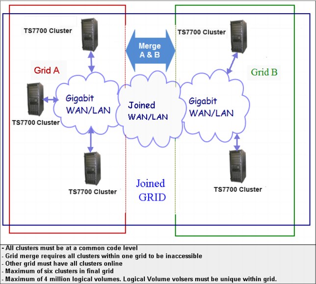
Figure 6-20 Grid merge example
Preparation
You can add an existing TS7700 Cluster to another existing TS7700 Cluster to form a grid for the first time or to create a larger grid. You can also merge a stand-alone cluster to an existing grid, or merge two grids together.
You can merge two existing TS7700 grids to create a larger grid. This solution enables you to keep redundant copies of data within both grids during the entire merge process versus needing to remove one or more clusters first and exposing them to a single copy loss condition.
When performing a merge, it is important to note that the actual data does not get copied from one cluster to another. This process creates place holders for all of the logical volumes in the final grid. When merging grids, the process is initiated to a single cluster in the grid and the information is populated to all members of the grid.
The grid or cluster chosen to be inaccessible during the merge process has its indexes changed to not conflict with the other grid or cluster. Check with your SSR for planning information.
Ensure that no overlapping logical volume ranges or physical volume ranges exist. The merge process detects that situation. You need to check for duplicate logical volumes and, on TS7740 clusters, for duplicate physical volumes. Logical volume ranges in a TS7700 Virtualization Engine must be unique. If duplicate volumes are identified during the merge process, the process stops before the merge starts the actual merge process.
Host configuration changes
If you merge clusters or grids together, you must plan which logical partition (LPAR) will have access to which clusters and which device ranges in the grid in advance. These changes need to be prepared in each LPAR (HCD, SMS, and TCDB):
•All HCDs, subsystem IDs, and Port IDs must be updated, and the cabling must be done correctly.
•Define the new distributed Library ID to SMS. Check with the IBM SSR for the appropriate ID number.
•The Tape Management System (TMS) and volume category (volcat) definitions must be updated within their respective Storage Groups. These updates are necessary to maintain continued access to the original volumes that were created when the systems were configured as stand-alone clusters.
•Review your DEVSUPxx members in all connected LPARs to ensure that no duplicate scratch or private categories are defined.
Management and data policy planning
Check the following information:
•Constructs in a cluster, which are already in the existing cluster, will be updated with the content of the existing cluster.
•Constructs in a cluster, which exist in the existing cluster but not in the merging cluster, will be copied.
•Constructs in a cluster, which exist in the merging cluster but not in the existing cluster, will be kept, but not copied to the existing cluster or grid.
Figure 6-21 shows the Management Class definition of the merging cluster and the two-cluster grid before the merge.
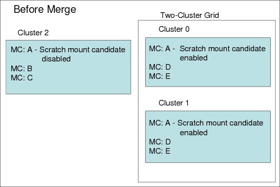
Figure 6-21 Management Class definition before merge
Figure 6-22 shows the Management Class definition of the merging cluster and the two-cluster grid after the merge.

Figure 6-22 MC definition after merge
If categories and constructs are already defined on the merging cluster, verify that the total number of each category and construct that will exist in the grid does not exceed 256. If necessary, delete existing categories or constructs from the joining or merging clusters before the grid upgrade occurs.
Each TS7700 grid supports a maximum of 256 of each of the following categories and constructs:
•Scratch Categories
•Management Classes
•Data Classes
•Storage Classes
•Storage Groups
Logical volume considerations
The TS7700 Virtualization Engine default number of supported logical volumes is 1,000,000. With Release 3.0, you can add support for more logical volumes in 200,000 volume increments using FC5270, up to a total of 4,000,000 logical volumes (2,000,000 million maximum on V06/VEA). The number of logical volumes supported in a grid is set by the cluster with the smallest number of FC5270 increments installed.
If the current combined number of logical volumes in the clusters to be joined exceeds the maximum number of supported logical volumes, some logical volumes must be moved to another library or deleted to reach the allowed grid capacity. To maximize the full number of logical volumes supported on the grid, all clusters must have the same quantity of FC5270s installed. If feature counts do not match and the final merged volume count exceeds a particular clusters feature count, further inserts are not allowed until the feature counts on those clusters are increased.
Minimum microcode level and feature code for merge
Before the merge of a cluster or a grid into another grid, the following restrictions apply to the merge process:
•When you merge from one cluster or a grid to another grid, all clusters in the existing grids are automatically merged. The merging cluster must be offline and the cluster to be merged is only online if it has 8.21.x.x code or higher.
•A grid-to-grid merge is only supported at 8.21.x.x code or higher, and both grids must operate at the same microcode level.
•Merges are only supported when all clusters in the resulting grid are at the exact same code level.
•FC4015, Grid enablement, must be installed on all TS7700 clusters that operate in a grid configuration, and all clusters must operate at microcode level 8.7.0.x or higher.
•Both existing clusters and merging clusters must contain enough features to accommodate the total resulting volume count post merge, or the merge will fail.
•The merging cluster must contain FC5271 if the cluster to be merged has it installed.
•If the merging cluster has FC1035 installed, the client’s infrastructure must support 10 Gb.
Merge steps
Complete these steps to merge of the clusters or grids into a grid:
1. Arrange for these merge cluster tasks to be performed by the IBM SSR:
a. Verify the feature code.
b. Configure the grid IP address on all clusters and test.
c. Configure and test Autonomic Ownership Takeover Manager (AOTM), when needed. See Chapter 2, “Architecture, components, and functional characteristics” on page 13 for more information.
2. Change HCD channel definitions.
Define the new channels and the device units’ addresses in HCD. For more information about HCD, see 4.3.1, “Host configuration definition” on page 148 and 5.4, “Hardware configuration definition” on page 186.
3. Change SMS and TCDB.
With the new grid, you need one composite library and up to six distributed libraries. All distributed libraries and cluster IDs must be unique. You must now define the new added distributed library in SMS. Make sure to enter the correct Library-ID delivered by the SSR.
4. Activate the IODF and the SMS definitions and issue an OAM restart (if it was not done after the SMS activation).
5. Vary devices online to all connected hosts. After a cluster is merged to a cluster in an existing grid, all clusters in the existing grid are automatically merged. Now, you are ready to validate the grid.
6. Run test jobs to read and write to volumes from all the clusters. Remember, you must verify all LPARs in the sysplex.
7. Modify copy policies and Retain Copy mode in the Management Class definitions according to your needs. Check all constructs on the MI of both clusters and ensure that they are set correctly for the new configuration. See 2.3.25, “Copy Consistency Point: Copy policy modes in a multicluster grid” on page 77 for more information.
8. Test write and read with all the clusters and validate the copy policies to match the previously defined Copy Consistency Points.
9. If you want part or all of the existing logical volumes to be replicated to the new cluster, this can be done in different ways. IBM has tools, such as PRESTAGE, to support these actions. The logical volumes must be read or referred to retrieve the new management policies that you define. The tools are available at the following URL:
6.6 Removing clusters from a grid
FC4016, Remove Cluster from Grid, delivers instructions for a one-time process to remove/unjoin a cluster (either TS7720 or TS7740) from a grid configuration. It can be used for removing one cluster from a two-cluster to six-cluster domain. Subsequent invocations can be run to remove multiple clusters from the grid configuration.
After the removal, a Cluster Cleanup (FC4017) can be run. FC4017 is required if the removed cluster is going to be reused. A Cluster Cleanup removes the previous data from cache and returns the cluster to a usable state, similar to a new TS7700 included by manufacturing, keeping the existing feature codes in place. Both feature codes are one-time use features.
You can delay the cluster cleanup for a short period while the TS7700 grid continues operation to ensure that all volumes are present after the removal of the TS7700 cluster. If the removed cluster needs to retain its data and be accessed as an independent cluster or grid, a service offering is available to complete the process. Contact your sales representative
for information.
for information.
The client is responsible for determining how to handle the volumes that only have a Copy Consistency Point at the cluster that is being removed (eject them, move them to the scratch category, or activate a Management Class change on a mount/demount to get a copy on another cluster). This process needs to be done before starting the removal process. A new Bulk Volume Information Retrieval (BVIR) option Copy Audit or COPYRFSH is provided for generating a list of inconsistent volumes to help you.
The removal of the cluster from the grid is concurrent with client operations on the remaining clusters, but some operations are restricted during the removal process. During this time, inserts, ejects, and exports are inhibited. Generally, run the removal of a cluster from the grid during off-peak hours.
No data, on cache or tapes, on the removed cluster will be available after the cluster has been removed with the completion of FC4016. The cluster cannot be rejoined with the existing data. There is a special service offering to rejoin a cluster with existing data, if this particular operation is wanted. Contact your IBM representative for details of this service offering.
No secure erase or low-level format will be done on the tapes or the cache as part of FC4016 or FC4017. If the client requires data secure erase of the tape volume cache contents, it is a contracted service for a fee. Consider delaying the cluster cleanup for a short time while the TS7700 grid continues operation to ensure that all volumes are present after the removal of the TS7700 cluster.
6.6.1 Reasons to remove a cluster
Use FC4016 for the following tasks.
Data center consolidation
A client is consolidating data centers by collecting the data from remote data centers and using the TS7700 grid to move the data to their centralized data center. In this scenario, the client potentially has two clusters at the primary data center for high availability. The third cluster is at a different data center. To consolidate the data center, it is necessary to copy the data from the third cluster to the existing grid in the primary data centers. The third cluster is joined with the two existing clusters and the data is copied with grid replication.
After all of their data has been copied to the primary data center TS7700s, the client can remove the third cluster from the remote data center and clean up the data from it. This TS7700 can now be relocated and the process can be repeated.
TS7720, TS7720T, or TS7740 reuse
A client has a multisite grid configuration, and the client no longer requires a TS7720, TS7720T, or TS7740 at one site. The client can remove this cluster (after all required data has been copied, removed, or expired) and use this resource in another role. Before the cluster can be used, it needs to be removed from the grid domain and cleaned up.
6.6.2 High-level description of the process
The following high-level preparation activities occur on the removal of a cluster from an existing domain:
•You must determine whether there are any volumes that are only available on the cluster to be removed (for example, Management Classes defined to only have a copy on one cluster, or auto removal from TS7720). Before the removal, you must create consistent copies on other clusters in the domain. Reference the BVIR Copy Audit function described in the IBM Virtualization Engine TS7700 Series Bulk Volume Information Retrieval Function User’s Guide Version 1.5 white paper at the following website:
•If volumes that only have a valid copy on the cluster are to be removed, you must determine how to handle those volumes by performing one or more of the following tasks:
– Eject the logical volumes (see “Ejecting logical volumes” on page 590).
– Move the volumes to a scratch category.
– Activate a Management Class change on the volume with a mount or unmount to get a copy made on another cluster.
•Ensure that there are no volumes in the damaged category. You can use the Repair Logical Volumes menu under the MI panel to repair them.
•Modify Management Classes so that the removed cluster is no longer the target for copies.
•If you have microcode level 8.6.0.x or higher installed and the cluster being removed is part of a cluster family, the cluster must be removed from the family before the removal by using the TS7700 MI.
|
Note: If at least one remaining cluster in the grid is at code level 8.7.0.134 or later, you can use one of those clusters to perform the removal of another cluster by using FC4016 even if the grid contains two different code versions. Consult with your IBM SSR for the code version prerequisites for FC4016.
A copy consistency check is run at the beginning of the process. Do not skip consistency checks unless it is a disaster recovery (DR) unjoin or you can account for why a volume is inconsistent. Failure to do this can result in data loss when the only valid copy was present on the removed cluster.
After a cluster is removed, you might want to modify the host configuration to remove the LIBPORT IDs associated with the removed cluster.
|
..................Content has been hidden....................
You can't read the all page of ebook, please click here login for view all page.