

IBM TS7700 implementation
This chapter describes how to implement the IBM TS7700 Virtualization Engine on the IBM System z host systems. From a software perspective, differences exist between the IBM TS7740 Virtualization Engine, the IBM TS7720 Virtualization Engine, and the IBM TS7720T Virtualization Engine. If no specific differences are indicated, the implementation steps apply to both. Otherwise, the differences are explained in each relevant step.
This chapter includes the following sections:
For more information about defining a tape subsystem in a DFSMS environment, see IBM TS3500 Tape Library with System z Attachment: A Practical Guide to Enterprise Tape Drives and TS3500 Tape Automation, SG24-6789.
|
Important: IBM 3494 Tape Library attachment is not supported at Release 2.0 and later.
|
5.1 TS7700 Virtualization Engine implementation
The following sections describe the implementation and installation tasks to set up the TS7700 Virtualization Engine. The TS7700 Virtualization Engine includes the IBM TS7720 Virtualization Engine, the IBM TS7740 Virtualization Engine, and the IBM TS7720T Virtualization Engine. Specific names are used in this chapter if a certain task only applies to one of the three, because there are slight differences between the TS7720 Virtualization Engine, the TS7740 Virtualization Engine, and the TS7720T Virtualization Engine.
The TS7720 Virtualization Engine does not have a tape library attached, so the implementation steps related to a physical tape library, IBM System Storage TS3500 Tape Library, do not apply to the TS7720 Virtualization Engine. They do apply to the TS7720T, however, and all of the steps from the TS7720 section, the TS7740 section, and the TS3500 section need to be followed.
You can install the TS7740 or TS7720T Virtualization Engine together with your existing TS3500 Tape Library. Because the Library Manager functions are in the TS7700 Virtualization Engine microcode, the TS7740 or TS7720T manage all necessary operations, so the IBM TotalStorage 3953 Tape System is no longer required to attach these models.
Implementation tasks
The TS7700 Virtualization Engine implementation can be logically separated into three major sections:
•TS7740 or TS7720T Virtualization Engine and tape library setup
Use the TS7740 or TS7720T Virtualization Engine and the TS3500 Tape Library interfaces for these setup steps:
– Defining the logical library definitions of the TS7740 or TS7720T Virtualization Engine, such as physical tape drives and cartridges using the TS3500 Tape Library Specialist, which is the web browser interface with the TS3500 Tape Library.
– Defining specific settings, such as encryption, and inserting logical volumes into the TS7740 or TS7720T Virtualization Engine. You can also use the Management Interface (MI) to define logical volumes, management policies, and volume categories.
This chapter provides details about these implementation steps.
•TS7700 Hardware input/output (I/O) configuration definition
This section relates to the system generation. It consists of processes, such as FICON channel attachment to the host, hardware configuration definition (HCD) or input/output configuration program (IOCP) definitions, and missing-interrupt handler (MIH) settings. This activity can be done before the physical hardware installation and it can be part of the preinstallation planning.
•TS7700 Virtualization Engine software definition
This is where you define the new virtual tape library to the individual host operating system. In a System z environment with Data Facility Storage Management Subsystem (DFSMS)/IBM MVS™, this includes updating DFSMS automatic class selection (ACS) routines, object access method (OAM), and your tape management system during this phase. You also define Data Class (DC), Management Class (MC), Storage Class (SC), and Storage Group (SG) constructs and selection policies, which are passed to the TS7700 Virtualization Engine.
These three groups of implementation tasks can be done in parallel or sequentially. HCD and host definitions can be completed before or after the actual hardware installation.
5.2 TS3500 Tape Library definitions (TS7740 or TS7720T Virtualization Engine)
Use this section if you are implementing the TS7740 or TS7720T Virtualization Engine and a TS3500 Tape Library in a System z environment. If your TS7700 Virtualization Engine does not have an associated tape library (TS7720), see 5.3, “Setting up the TS7700 Virtualization Engine” on page 186.
Your IBM service support representative (SSR) performs the hardware installation of the TS7740 or TS7720T Virtualization Engine, its associated tape library, and the frames. This installation does not require your involvement other than the appropriate planning. See Chapter 4, “Preinstallation planning and sizing” on page 115 for details.
|
Clarification: The steps described in this section relate to the installation of a new IBM TS3500 Tape Library with all the required features, such as Advanced Library Management System (ALMS), already installed. If you are attaching an existing IBM TS3500 Tape Library that is already attached to Open Systems hosts to System z hosts also, see IBM TS3500 Tape Library with System z Attachment: A Practical Guide to Enterprise Tape Drives and TS3500 Tape Automation, SG24-6789, for extra actions that might be required.
|
The following tasks are for TS3500 library definition. For the detailed procedure, see 8.3.1, “TS3500 Tape Library with a TS7740 and TS7720T Virtualization Engine” on page 481.
•Defining a logical library
– Ensuring that ALMS is enabled
– Creating a new logical library with ALMS
– Setting the maximum cartridges for the logical library
•Adding drives to the logical library
•Defining control path drives
Each TS7740 or TS7720T Virtualization Engine requires four control path drives defined.
•Defining the Encryption Method for the new logical library
•Defining Cartridge Assignment Policies
•Inserting TS7740 or TS7720T Virtualization Engine physical volumes
•Assigning cartridges in the TS3500 Tape Library to the logical library partition
This procedure is necessary only if a cartridge was inserted, but a Cartridge Assignment Policy (CAP) was not provided in advance.
5.3 Setting up the TS7700 Virtualization Engine
This section describes the tasks to set up the TS7700 Virtualization Engine.
5.3.1 Definitions for TS7740 or TS7720T Virtualization Engines
If you have a TS7720, skip to 5.3.2, “TS7700 Virtualization Engine definitions” on page 186. For the detailed procedures, see 8.3.2, “TS7740 or TS7720T Virtualization Engine definitions” on page 498.
The tasks listed in this section are for TS7740 or TS7720T Virtualization Engine only:
•Defining VOLSER ranges for physical volumes
•Defining physical volume pools (TS7740 or TS7720T Virtualization Engine):
– Reclaim threshold setting
– Inhibit Reclaim schedule
5.3.2 TS7700 Virtualization Engine definitions
Use the TS7700 MI to continue with the TS7700 Virtualization subsystem setup. For more information, see 8.3.3, “TS7700 Virtualization Engine definitions” on page 514.
•Defining scratch categories and logical volume expiration time
•Defining TS7700 constructs
To use the Outboard Policy Management functions, you must define four constructs:
– Storage Group (SG)
– Management Class (MC)
– Storage Class (SC)
– Data Class (DC)
•TS7700 licensing
•Defining Encryption Key Server (EKS) addresses
•Defining Simple Network Management Protocol (SNMP)
•Cluster Network Setting
•Enabling Internet Protocol Security (IPSec)
•Security Settings
•Inserting logical virtual volumes
5.4 Hardware configuration definition
This section describes the process of defining the TS7700 Virtualization Engine through the hardware configuration definition (HCD) interface. Usually, HCD definitions are made by IBM z/OS system administrators. A helpful approach is to complete a table with all of the definitions that the administrators need to be able to create HCD, and then give the table to the administrators.
Table 5-1 is an example for a stand-alone cluster. In general, all of the blank cells must be completed by system administrators, because they know what channels are free, what control unit (CU) numbers are free, and so on.
Table 5-1 HCD definitions table for Cluster 0
|
CHPID
|
CU
|
CUADD
|
Link
|
Devices
|
ADD
|
LIB-ID
|
Libport
|
|
|
|
0
|
|
|
00-0F
|
|
01
|
|
|
|
1
|
|
|
00-0F
|
|
02
|
|
|
|
2
|
|
|
00-0F
|
|
03
|
|
|
|
3
|
|
|
00-0F
|
|
04
|
|
|
|
4
|
|
|
00-0F
|
|
05
|
|
|
|
5
|
|
|
00-0F
|
|
06
|
|
|
|
6
|
|
|
00-0F
|
|
07
|
|
|
|
7
|
|
|
00-0F
|
|
08
|
|
|
|
8
|
|
|
00-0F
|
|
09
|
|
|
|
9
|
|
|
00-0F
|
|
0A
|
|
|
|
A
|
|
|
00-0F
|
|
0B
|
|
|
|
B
|
|
|
00-0F
|
|
0C
|
|
|
|
C
|
|
|
00-0F
|
|
0D
|
|
|
|
D
|
|
|
00-0F
|
|
0E
|
|
|
|
E
|
|
|
00-0F
|
|
0F
|
|
|
|
F
|
|
|
00-0F
|
|
10
|
5.4.1 Defining devices through HCD
You can define up to 16 CUs with 16 devices each per cluster in the grid configuration. Use CUADD=0 through CUADD=7 and LIBPORT-IDs of 01 through 08 for the first eight CUs, as shown in Table 5-2.
Table 5-2 CUADD and LIBPORT-ID for the first set of 256 virtual devices
|
CU
|
1
|
2
|
3
|
4
|
5
|
6
|
7
|
8
|
|
CUADD
|
0
|
1
|
2
|
3
|
4
|
5
|
6
|
7
|
|
LIBPORT-ID
|
01
|
02
|
03
|
04
|
05
|
06
|
07
|
08
|
For the ninth to sixteenth CUs, use CUADD=8 through CUADD=F and LIBPORT-IDs of 09 through 10, as shown in Table 5-3.
Table 5-3 CUADD and LIBPORT-ID for the second set of virtual devices
|
CU
|
9
|
10
|
11
|
12
|
13
|
14
|
15
|
16
|
|
CUADD
|
8
|
9
|
A
|
B
|
C
|
D
|
E
|
F
|
|
LIBPORT-ID
|
09
|
0A
|
0B
|
0C
|
0D
|
0E
|
0F
|
10
|
|
------------------------ Add Control Unit ---------------------
CBDPCU10 Specify or revise the following values. Control unit number . . . . 0440 + Control unit type . . . . . 3490 + Serial number . . . . . . . __________ Description . . . . . . . . ________________________________ Connected to switches . . . 01 01 01 01 __ __ __ __ + Ports . . . . . . . . . . . D6 D7 D8 D9 __ __ __ __ + If connected to a switch: Define more than eight ports . 2 1. Yes 2. No Propose CHPID/link addresses and unit addresses. . . . . . . . .2 1. Yes
2. No F1=Help F2=Split F3=Exit F4=Prompt F5=Reset F9=Swap F12=Cancel |
Figure 5-1 Adding the first TS7700 Virtualization Engine CU through HCD (Part 1 of 2)
Specify the CU number and the type here (3490), as shown in Figure 5-1 on page 188, then press Enter. The window shown in Figure 5-2 is displayed. Select the processor to which the CU is to be connected.
|
-------------------------- Add Control Unit -------------------------
CBDPCU12 Specify or revise the following values. Control unit number . : 0440 Type . . . . . . : 3490 Processor ID . . . . . : PROC1 This is the main processor Channel Subsystem ID . : 0 Channel path IDs . . . . 40 50 60 70 __ __ __ __ + Link address . . . . . . D6 D7 D8 D9 __ __ __ __ + Unit address . . . . . . 00 __ __ __ __ __ __ __ + Number of units . . . . 16 ___ ___ ___ ___ ___ ___ ___ Logical address . . . . 0 + (same as CUADD) Protocol . . . . . . . . __ + (D,S or S4) I/O concurrency level . 2 + (1, 2 or 3) F1=Help F2=Split F4=Prompt F5=Reset F9=Swap F12=Cancel |
Figure 5-2 Adding the first TS7700 Virtualization Engine CU through HCD (Part 2 of 2)
|
Tip: When the TS7700 Virtualization Engine is not attached through Fibre Channel (FICON) directors, the link address fields are blank.
|
Repeating the previous process, define the second through sixteenth TS7700 Virtualization Engine virtual tape CUs, specifying the logical unit address (CUADD)=1 to F, in the Add Control Unit windows. The Add Control Unit summary window is shown in Figure 5-2.
To define the TS7700 Virtualization Engine virtual drives, use the Add Device window shown in Figure 5-3.
|
------------------------------- Add Device ---------------------------
CBDPDV10 Specify or revise the following values. Device number . . . . . . . . 0A40 (0000 - FFFF) Number of devices . . . . . . 16__ Device type . . . . . . . . . 3490_________ + Serial number . . . . . . . . __________ Description . . . . . . . . . ________________________________ Connected to CUs . . 0440 ____ ____ ____ ____ ____ ____ ____ + F1=Help F2=Split F3=Exit F4=Prompt F5=Reset F9=Swap F12=Cancel |
Figure 5-3 Adding the first 16 drives through HCD
After entering the required information, you can specify to which processors and operating systems the devices are connected to. Figure 5-4 shows the window used to update the processor’s view of the device.
|
------------------------ Define Device / Processor---------------------------
CBDPDV12 Specify or revise the following values. Device number . : 0A40 Number of devices . . . . : 16 Device type . . : 3490 Processor ID. . : PROC1 This is the main processor
Unit address . . . . . . . . . . 00 +(only necessary when different from the last 2 digits of device number) Time-Out . . . . . . . . . . . . No (Yes or No)
STADET . . . . . . . . . . . . . No (Yes or No) Preferred CHPID . . . . . . . . __ + Explicit device candidate list . No (Yes or No) F1=Help F2=Split F4=Prompt F5=Reset F9=Swap F12=Cancel |
Figure 5-4 HCD Define Device / Processor window
After entering the required information and specifying to which operating systems the devices are connected, the window in Figure 5-5 is displayed, where you can update the device parameters.
|
CBDPDV13 Define Device Parameters / Features Row 1 of 6
Command ===> __________________________________________ Scroll ===> PAGE
Specify or revise the values below.
Configuration ID . : AB MVS operating system
Device number . . : 0440 Number of devices :16
Device type . . . : 3490
Parameter /
Feature Value P Req. Description
OFFLINE Yes Device considered online or offline at IPL
DYNAMIC Yes Device supports dynamic configuration
LOCANY No UCB can reside in 31 bit storage
LIBRARY Yes Device supports auto tape library
AUTOSWITCH No Device is automatically switchable
LIBRARY-ID CA010 5-digit library serial number
LIBPORT-ID 01 2 digit library string ID (port number)
MTL No Device supports manual tape library
SHARABLE No Device is Sharable between systems
COMPACT Yes Compaction
***************************** Bottom of data ****************************
F1=Help F2=Split F4=Prompt F5=Reset F7=Backward
F8=Forward F9=Swap F12=Cancel F22=Command
|
Figure 5-5 Define Device Parameters HCD window
|
Tips:
•If you are defining drives that are installed in a system-managed IBM Tape Library, such as the TS7700 Virtualization Engine, you must specify LIBRARY=YES.
•If more than one System z host will be sharing the virtual drives in the TS7700 Virtualization Engine, specify SHARABLE=YES. This forces OFFLINE to YES. It is up to the installation to ensure the correct serialization from all attached hosts.
•You must use the composite library ID of the TS7700 Virtualization Engine in your HCD definitions.
•The distributed library IDs are not defined in HCD.
|
To define the remaining TS7700 Virtualization Engine 3490E virtual drives, repeat this process for each CU in your implementation plan.
5.4.2 Activate the I/O configuration
There are differences in the concurrent input/output definition file (IODF) activation process between a new tape library implementation and a configuration change made to an existing library. Changes to the virtual devices’ address range of an existing library is an example of where concurrent IODF activation is useful.
As an alternative to the procedures described next, you can always perform an initial program load (IPL) or restart of the system.
Installing a new tape library
If you are installing a TS7700 Virtualization Engine for the first time, from a host software definition point of view, this is an installation of a new library. When you are activating the IODF for a new tape library, the following steps must be completed to get the tape library or TS7700 Virtualization Engine online without an IPL of your systems:
1. Activate the IODF.
2. Run MVS console command VARY ONLINE to vary online the devices in the library. This command creates some of the control blocks. You see the following message:
IEA437I TAPE LIBRARY DEVICE(ddd), ACTIVATE IODF=xx, IS REQUIRED
3. Do the final ACTIVATE. This action is required to build the eligible device table (EDT) for MVS Allocation.
After activation, you can check the details using the DEVSERV QTAPE command. See 9.1.2, “MVS system commands” on page 571.
Modifications to an existing tape library
When you are modifying an existing tape library so that existing device addresses can be changed, complete the following steps:
1. Activate an IODF that deletes all devices from the library.
2. Activate an IODF that defines all of the devices of the modified library.
3. Run MVS console command VARY ONLINE to vary online the devices in the library. This creates some of the control blocks. You see the following message:
IEA437I TAPE LIBRARY DEVICE(ddd), ACTIVATE IODF=xx, IS REQUIRED
4. Do the final ACTIVATE.
Alternatively, you can use the DS QL,nnnnn,DELETE (where nnnnn is the LIBID) command to delete the library’s dynamic control blocks. If you have IODEF with LIBID and LIBPORT coded already, complete the following steps:
1. Use QLIB LIST to see whether the INACTIVE control blocks are deleted.
2. Use ACTIVATE IODF to redefine the devices.
3. Use QLIB LIST to verify that the ACTIVE control blocks are properly defined.
If LIBRARY-ID (LIBID) and LIBPORT-ID are not coded, complete the following step:
1. Run MVS console command VARY ONLINE to vary on the devices in the library. This creates some control blocks, and you see the following message:
IEA437I TAPE LIBRARY DEVICE(ddd), ACTIVATE IODF=xx, IS REQUIRED
5.5 Set values for the Missing Interrupt Handler
The TS7700 Virtualization Engine emulates 3490E devices and does not automatically communicate the missing-interrupt handler (MIH) timeout values to the host operating system in the Read Configuration Data channel control word (CCW).
|
Important: An MIH value of 45 minutes is preferable for the virtual devices in a multicluster grid when a copy consistency for the remote clusters is set to RUN.
|
You must specify the MIH timeout value for IBM 3490E devices. The value applies only to the virtual 3490E drives and not to the real IBM TS1140/TS1130/TS1120/3592 drives that the TS7740 Virtualization Engine manages in the back end. Remember that the host only knows about logical 3490E devices.
Table 5-4 summarizes the minimum values, which might need to be increased, depending on specific operational factors.
Table 5-4 Tape device MIH values
|
Tape device
|
MIH
|
|
TS7700 Virtualization Engine stand-alone grid with 3490E emulation drives
|
20 minutes
|
|
TS7700 Virtualization Engine multicluster grid with 3490E emulation drives
|
45 minutes
|
|
TS7700 Virtualization Engine multicluster grid with 3490E emulation drives and not using rewind unload copy policies
|
20 minutes
|
Specify the MIH values in PARMLIB member IECIOSxx. Alternatively, you can also set the MIH values through the System z operator command SETIOS. This setting is available until it is manually changed or until the system is initialized.
Use the following statements in PARMLIB, or manual commands to display and set your MIH values:
•You can specify the MIH value in the IECIOSxx PARMLIB member:
MIH DEV=(0A40-0A7F),TIME=45:00
•To manually specify MIH values for emulated 3490E tape drives, use this command:
SETIOS MIH,DEV=(0A40-0A7F),TIME=45:00
– To display the new settings, use this command:
D IOS,MIH,DEV=0A40
– To check the current MIH time, use this command:
D IOS,MIH,TIME=TAPE
For more information about MIH settings, see MVS Initialization and Tuning Reference, SA22-7592.
During IPL (if the device is defined to be ONLINE) or during the VARY ONLINE in process, some devices (such as the IBM 3590/3592 physical tape devices) might present their own MIH timeout values through the primary/secondary MIH timing enhancement that is contained in the self-describing data for the device. The primary MIH timeout value is used for most I/O commands, but the secondary MIH timeout value can be used for special operations, such as long-busy conditions or long-running I/O operations.
Any time that a user specifically sets a device or device class to an MIH timeout value that is different from the default for the device class that is set by IBM, that value overrides the device-established primary MIH timeout value. This implies that if an MIH timeout value that is equal to the MIH default for the device class is explicitly requested, iOS does not override the device-established primary MIH timeout value. To override the device-established primary MIH timeout value, you must explicitly set a timeout value that is not equal to the MIH default for the device class.
5.6 TS7700 Virtualization Engine software definitions
This section describes the software definition considerations for implementing the TS7700 Virtualization Engine in z/OS.
The TS7700 Virtualization Engine must be defined as a new tape library with emulated 3490E Tape Drives from the host system. For more information about defining this configuration, see IBM TotalStorage 3494 Tape Library: A Practical Guide to Tape Drives and Tape Automation, SG24-46322.
To use the TS7700 Virtualization Engine, at least one Storage Group must be created to enable the TS7700 Virtualization Engine tape library virtual drives to be allocated by the storage management subsystem (SMS) ACS routines. Because all of the logical drives and volumes are associated with the composite library, only the composite library can be defined in the Storage Group.
See the following resources for information about host software implementation tasks for IBM tape libraries:
•z/OS DFSMS OAM Planning, Installation, and Storage Administration Guide for Tape Libraries, SC23-6867
•IBM TS3500 Tape Library with System z Attachment: A Practical Guide to Enterprise Tape Drives and TS3500 Tape Automation, SG24-6789
If your tape management system (TMS) is DFSMS Removable Media Manager (DFSMSrmm), the following manuals can be useful:
•IBM Redbooks Publication: DFSMSrmm Primer, SG24-5983
•z/OS DFSMSrmm Implementation and Customization Guide, SC23-6874
If this installation is the first SMS tape library at this host, additional steps are required. The full product documentation for your Tape Management System needs to be consulted, in addition to the OAM PISA listed in the previous bullet.
Complete the following steps to define the TS7700 Virtualization Engine Tape Library in an existing z/OS SMStape environment:
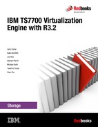
1. Use the ISMF Library Management → Tape Library → Define panel to define the tape library as a DFSMS resource. Define the composite library and one or more distributed libraries. Remember that library names cannot start with a “V”. In the following figures, we define one composite library named IBMC1 and a single distributed library named IBMD1.
|
Remember: Library ID is the only field that applies for the distributed libraries. All other fields can be blank or left as the default.
|

Figure 5-6 Define Composite Tape Library Screen1

Figure 5-7 Define Composite Tape Library Screen2
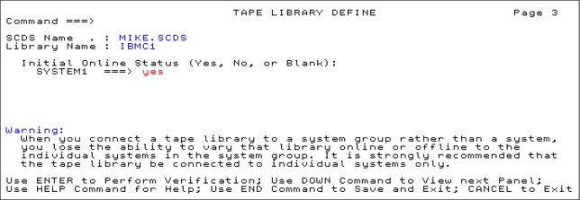
Figure 5-8 Define Composite Tape Library Screen3
Figure 5-9 illustrates defining the distributed tape library.
Figure 5-9 Define Distributed Tape Library
2. Using the Interactive Storage Management Facility (ISMF), create or update the Data Classes (DCs), Storage Classes (SCs), and Management Classes (MCs) for the TS7700 Virtualization Engine. Ensure that these defined construct names are the same as those you have defined at the TS7700 Virtualization Engine Management Interface (MI).
3. Using ISMF, create the Storage Groups (SGs) for the TS7700 Virtualization Engine. Ensure that these defined construct names are the same as those you have defined at the TS7700 Virtualization Engine MI.
The composite library must be defined in the Storage Group. Do not define the distributed libraries in the Storage Group.
|
Tip: At OAM address space initialization, if a distributed library is defined to a Storage Group, the warning message CBR3017I is generated indicating that the distributed library is incorrectly defined to the Storage Group.
|
4. Update the ACS routines to assign the constructs needed to use the TS7700 and then translate, test, and validate the ACS routines.
5. Customize your TMS to include the new volume ranges and library name. For DFSMSrmm, this involves EDGRMMxx updates for VLPOOL and LOCDEF statements, in addition to any OPENRULE and PRTITION statements needed. Remember that if you leave REJECT ANYUSE(*) in your EDGRMMxx member, you cannot use any tape volume serial numbers (VOLSERs) not previously defined to RMM.
6. Consider if your current TMS database or control data set (CDS) has sufficient space for the added library, dataset, and volume entries. For DFSMSrmm, consult the IBM Redbooks Publication DFSMSrmm Primer, SG24-5983 under topic 3.1.10 Creating the DFSMSrmm CDS.
7. Modify the SYS1.PARMLIB members DEVSUPxx for new categories, see 4.3.4, “Sharing and partitioning considerations” on page 150. It is suggested that the DEVSUPxx default categories should always be changed to prevent disruption of library operations. See z/OS V2R1.0 DFSMS OAM Planning, Installation, and Storage Administration Guide for Tape Libraries, SC23-6867 under topic Changing the library manager category assignments in an ATLDS.
8. Consider updating COMMANDxx to vary the library online at IPL if you have not already set it to come online during the definition of the library through ISMF., 9.1.1, “DFSMS operator commands” on page 568.
9. In a Grid environment, it might be desirable to update the ALLOCxx parmlib member SYSTEM TAPELIB_PREF to balance workloads. The default algorithm EQUAL works well if the libraries under consideration have an equal number of online devices, otherwise it might be useful to consider using BYDEVICES.
10. Consider the current size of the volume catalogs and the additional space that is required for the new volume and library entries. For a TS7700 with 100,000 volumes, at least 32 cylinders should be allocated. To more precisely estimate the space allocation requirements in the tape volume catalog, use the following steps:
a. Estimate the number of tape library entries and tape volume entries to be cataloged in the VOLCAT. Each tape library entry requires 320 bytes and each volume entry requires 275 bytes.
b. Divide the total number of bytes by 1024 to determine the number of kilobytes, or by 1,048,576 to determine the number of megabytes.
For more guidance see z/OS DFSMS Managing Catalogs, SC23-6853 Chapter 3 under the topic Defining Names for a Tape Volume Catalog.
11. Activate the new Source Control Data Set (SCDS) with the SETSMS SCDS (scdsname) command.
12. Restart the OAM address space with F OAM,RESTART command. SMS SCDS activation initiates an OAM restart if parameter RESTART=YES is specified in the OAM startup procedure in PROCLIB and in that case a manual restart is not needed.
13. Define any security profiles required.
14. Vary the composite library and distributed libraries online. See 9.1.1, “DFSMS operator commands” on page 568.
15. Vary the TS7700 Virtualization Engine virtual drives online. See 9.1.1, “DFSMS operator commands” on page 568.
For more information about defining a tape subsystem in a DFSMS environment, see IBM TS3500 Tape Library with System z Attachment: A Practical Guide to Enterprise Tape Drives and TS3500 Tape Automation, SG24-6789.
..................Content has been hidden....................
You can't read the all page of ebook, please click here login for view all page.