

Operation
This chapter provides information about how to operate and configure the IBM TS7700 Virtualization Engine by using the Management Interface (MI). The following topics
are covered:
are covered:
•IBM TS7700 Virtualization Engine MI
•Basic operations
•Tape cartridge management
•Managing logical volumes
•Recovery scenarios
This chapter also includes information about these topics:
•TS3500 Tape Library Specialist
For general guidance about how to operate the IBM TS3500 tape library, see the following IBM Redbooks publication:
IBM TS3500 Tape Library with System z Attachment A Practical Guide to Enterprise Tape Drives and TS3500 Tape Automation, SG24-6789
8.1 User interfaces
To successfully operate your TS7700 Virtualization Engine, you need to understand its concepts and components. This chapter combines the components and functions of the TS7700 Virtualization Engine into two groups:
•The logical view
•The physical view
Each component and each function belong to only one view.
The logical view is named the host view. From the host allocation point of view, there is only one library, called the composite library. Before R3.2 of Licensed Level of Code (LIC), a composite library could have up to 1536 virtual addresses for tape mounts, considering a six-cluster grid (256 devices or 16 logical control units per cluster).
R3.2 introduces support for 496 devices per cluster (available with feature code 5275), making up for 3968 virtual tape devices in a grid of six fully configured clusters (z/OS also needs an authorized program analysis report (APAR) to grow from the previous limit of 2048 to 4096 per grid or composite library). Read more about this in Chapter 2, “Architecture, components, and functional characteristics” on page 13. The logical view includes virtual volumes and virtual tape drives.
The host is only aware of the existence of the underlying physical libraries because they are defined through Interactive Storage Management Facility (ISMF) in a z/OS environment. The term distributed library is used to denote the physical libraries and TS7700 Virtualization Engine components that are part of one cluster of the multicluster grid configuration.
The physical view is the hardware view that deals with the hardware components of a stand-alone cluster or a multicluster grid configuration. In a TS7740 or TS7720T Virtualization Engine, it includes the TS3500 Tape Libraries and 3592 J1A, TS1120, TS1130, or TS1140 tape drives.
The following operator interfaces for providing information about the TS7700 Virtualization Engine are available:
•Object access method (OAM) commands are available at the host operator console. These commands provide information about the TS7700 Virtualization Engine in stand-alone and grid environments. This information represents the host view of the components within the TS7700 Virtualization Engine. Other z/OS commands can be used against the virtual addresses. This interface is described in Chapter 9, “Host Console Operations” on page 567.
•Web-based management functions are available through web-based user interfaces (UIs). You can access the web interfaces with the following browsers:
– Mozilla Firefox 13.0, Firefox 17.0, Firefox 17.x ESR, Firefox 19.x, Firefox 24.0, Firefox 24.x ESR
– Microsoft Internet Explorer Version 9.x or 10.x
Enable cookies and disable the browser’s function of blocking pop-up windows for the Management Interface usage.
|
Attention: Only supported web browsers should be used for management. Non-supported web browser versions might cause some MI panes to malfunction.
|
•Considering the overall TS7700 implementation, two different web-based functions
are available:
are available:
– The TS3500 Tape Library Specialist, which enables management, configuration and monitoring of the IBM TS3500 Tape Library. The TS3500 Tape Library is used in TS7700 implementation for tape attached models.
– The TS7700 Virtualization Engine Management Interface (MI) is used to run all TS7700 Virtualization Engine configuration, setup, and monitoring actions.
Call Home Interface: This interface is activated on the TS3000 System Console (TSSC) and enables Electronic Customer Care (ECC) by IBM System Support. Alerts can be sent out to IBM RETAIN systems and the IBM service support representative (SSR) can connect through the TSSC to the TS7700 Virtualization Engine and the TS3500 Tape Library.
8.1.1 TS3500 Tape Library Specialist
The IBM System Storage TS3500 Tape Library Specialist web interface, which can be called from the TS7700 Virtualization Engine interface, enables you to monitor and configure most of the library functions from the web.
Figure 8-1 shows the TS3500 Tape Library Specialist welcome window with the System Summary.

Figure 8-1 TS3500 Tape Library Specialist welcome window
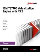
Figure 8-2 shows a flowchart of the functions that are available, depending on the configuration of your TS3500 Tape Library.
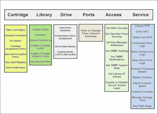
Figure 8-2 TS3500 Tape Library Specialist functions
The TS3500 windows are mainly used during the hardware installation phase of the TS7740 and TS7720T Virtualization Engine. The activities involved in installation are described in 8.3.1, “TS3500 Tape Library with a TS7740 and TS7720T Virtualization Engine” on page 481.
8.1.2 Call Home and Electronic Customer Care
The tape subsystem components include several external interfaces that are not directly associated with data paths. Instead, these interfaces are associated with system control, service, and status information. They support customer interaction and feedback, and attachment to IBM remote support infrastructure for product service and support.
These interfaces and facilities are part of the IBM System Storage Data Protection and Retention (DP&R) storage system. The main objective of this mechanism is to provide a safe and efficient way for the System Call Home (Outbound) and Remote Support (Inbound) connectivity capabilities.
See the document IBM Data Protection & Retention System Connectivity and Security, WP100704, for a complete description of the connectivity mechanism and related security aspects:
The Call Home function generates a service alert automatically when a problem occurs with one of the following components:
•TS3500 Tape Library
•3592 tape controllers models J70, C06, and C07
•TS7700 Virtualization Engine
Error information is transmitted to the IBM System Storage TS3000 System Console for service, and then to the IBM Support Center for problem evaluation. The IBM Support Center can dispatch an IBM SSR to the client installation. Call Home can send the service alert to a pager service to notify multiple people, including the operator. The SSR can deactivate the function through service menus, if required.
See Figure 8-3 for a high-level view of call home and remote support capabilities.
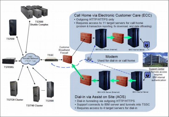
Figure 8-3 Call home and remote support functions
In addition to Release 3.2 of Licensed Internal Microcode, a new IBM System Storage TS3000 System Console (TSSC) model is introduced. The TSSC can be ordered as a rack mount feature of several products. Feature code 2725 provides the new enhanced TS3000 System Console. Physically, the TS3000 TSSC is a standard rack 1U mountable server that is installed within the 3592 F05 frame.
Feature code 2748 provides an optical drive, needed for the Licensed Internal Code changes and log retrieval. With the new TS3000 System Console provided by FC2725, remote data link or call home by using an analog telephone line and modem is not supported any longer. Dial-in function through Assist On Site (AOS) and Call Home with Electronic Customer Care functions are both available using HTTP/HTTPS broadband connection.
Electronic Customer Care
Electronic Customer Care (ECC) provides a method to connect IBM storage systems with IBM remote support. The package provides supports for dial-out communication for broadband Call Home and modem connection. All information sent back to IBM is Secure Sockets Layer (SSL) encrypted. Modem connectivity protocols follow similar standards as for direct connected modems. Broadband connectivity uses both HTTP and HTTPS protocols.
|
Note: Modem is not supported any longer in the new TS3000 System Console model.
|
ECC is a family of services featuring problem reporting by opening a problem management record (PMR), sending data files, and downloading fixes. The ECC client provides a coordinated end-to-end electronic service between IBM business operations, its IBM Business Partners, and its clients. The ECC client runs electronic serviceability activities, such as problem reporting, inventory reporting, and fix automation. This becomes increasingly important because customers are running heterogeneous, disparate environments, and are seeking a means to simplify the complexities of those environments.
The TSSC enables you to use a Proxy Server or Direct Connection. Direct Connection implies that there is not an HTTP proxy between the configured TS3000 and the outside network to IBM. Selecting this method requires no further setup. ECC supports customer-provided HTTP proxy. Additionally, a customer might require all traffic to go through a proxy server. In this case, the TSSC connects directly to the proxy server, which initiates all communications to the Internet.
|
Note: All inbound connections are subject to the security policies and standards defined by the client. When a Storage Authentication Service, Direct Lightweight Directory Access Protocol (LDAP), or RACF policy is enabled for a cluster, service personnel (local or remote) are required to use the LDAP-defined service login.
Important: Be sure that local and remote authentication has been allowed, or that an account has been created to be used by service personnel, before enabling storage authentication, LDAP, or RACF policies.
|
The outbound communication associated with ECC call home can be through an Ethernet connection, a modem, or both, in the form of a failover setup. Modem is not supported in the new TS3000 System Console. The local subnet LAN connection between the TSSC and the attached subsystems remains the same. It is still isolated without any outside access. ECC adds another Ethernet connection to the TSSC, bringing the total number to three. These connections are labeled:
•The External Ethernet Connection, which is the ECC Interface
•The Grid Ethernet Connection, which is used for the TS7700 Virtualization Engine Autonomic Ownership Takeover Manager (AOTM)
•The Internal Ethernet Connection, used for the local attached subsystem’s subnet
All of these connections are set up using the Console Configuration Utility User Interface that is on the TSSC.
|
Note: The AOTM and ECC interfaces should be in different TCP/IP subnets. This avoids both communications from using the same network connection.
|
The TS7700 Virtualization Engine shows the events that originated a Call Home in the Events pane, under the Monitor icon.
Tivoli Assist On-site
Enhanced support capabilities include the introduction of Tivoli Assist On-site (AOS) to expand maintenance capabilities. This is a service function that is managed by an IBM SSR or by the client through the AOS customer interface. AOS is a tool that enables an authenticated session for remote TSSC desktop connections over an external broadband Ethernet adapter. An AOS session enables IBM remote support center representatives to troubleshoot issues with the system.
AOS uses the same network as broadband call home, and works on either HTTP or HTTPS. The AOS function is disabled, by default. When enabled, the AOS can be configured to run in either attended or unattended modes:
•Attended mode requires that the AOS session be initiated at the TSSC associated with the target TS7700 Virtualization Engine. This requires physical access by the IBM SSR to the TSSC or the client through the customer interface.
•Unattended mode, also called Lights Out mode, enables a remote support session to be established without manual intervention at the TSSC associated with the target TS7700 Virtualization Engine.
All AOS connections are outbound. In unattended mode, the session is established by periodically connecting to regional AOS relay servers to determine whether remote access is needed. If access has been requested, AOS authenticates and establishes the connection, enabling a remote desktop access to the TSSC.
|
Note: Remember that all authentications are subject to the Authentication policy in effect. See the information under 8.2.9, “The Access icon” on page 413.
|
8.2 TS7700 Virtualization Engine Management Interface
The TS7700 Virtualization Engine Management Interface (MI) is the primary interface to monitor and administer the TS7700 Virtualization Engine.
|
Tip: Starting with R3.0, a new graphical user interface (GUI) has been implemented. This gives the TS7700 MI an appearance and operation that is similar to other IBM Storage products management interfaces.
|
8.2.1 Connecting to the Management Interface
To connect to the TS7700 Virtualization Engine MI, complete the following steps:
1. The TS7700 Virtualization Engine must first be installed, configured, and online.
2. In the address field of a supported web browser, enter http://x.x.x.x
(where x.x.x.x is the virtual IP address that was assigned during installation). Press Enter or click Go in your web browser.
(where x.x.x.x is the virtual IP address that was assigned during installation). Press Enter or click Go in your web browser.
|
Tip: The following web browsers are currently supported:
•Firefox 13.0, Firefox 17.0, Firefox 17.x ESR, Firefox 19.x, Firefox 24.0, and
Firefox 24.x ESR •Internet Explorer 9 and 10
|
3. The virtual IP is one of three IP addresses that are provided during installation. If you want to access a specific cluster, the cluster must be specified when the IP address is entered as shown in Example 8-1, where Cluster 0 is accessed directly.
Example 8-1 IP address to connect to Cluster 0 in a grid
http://x.x.x.x/0/Console
4. If you are using your own name server, where you can associate a name with the virtual IP address, you can use the name rather than the hardcoded address for reaching the MI.
5. The login page for the MI displays as shown in Figure 8-4. Enter the default login name as admin and the default password as admin.
Figure 8-4 TS7700 Virtualization Engine MI login
After entering your password, you see the first web page presented by the MI, the Virtualization Engine Grid Summary, as shown in Figure 8-5 on page 297.
After security policies are implemented locally at the TS7700 Virtualization Engine cluster or by using centralized role-base access control (RBAC), a unique user identifier and password can be assigned by the administrator. The user profile can be modified to only provide functions applicable to the role of the user. All users might not have access to the same functions or views through the MI.
For more information, see 8.2.9, “The Access icon” on page 413.
Figure 8-5 shows a visual summary of the TS7700 Virtualization Engine Grid. It shows a four-cluster grid, the components, and health status. The composite library is depicted as a data center, with all members of the grid on the raised floor.
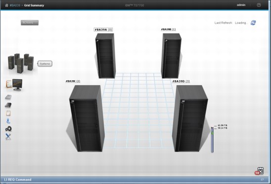
Figure 8-5 MI Virtualization Engine Grid Summary
Each cluster is represented by an image of the TS7700 Virtualization Engine, displaying the cluster’s nickname and ID, and the composite library name and Library ID.
The health of the system is checked and updated automatically at times determined by the TS7700 Virtualization Engine. Data displayed in the Grid Summary page is not updated in real time. The Last Refresh field, in the upper-right corner, reports the date and time that the displayed data was retrieved from the TS7700 Virtualization Engine. To populate the summary with an updated health status, click the Refresh icon near the Last Refresh field in the upper-right corner of Figure 8-5.
The health status of each cluster is indicated by a status sign next to its icon. The legend explains the meaning of each status sign. To obtain additional information about a specific cluster, click that component’s icon.
Library control with TS7700 Virtualization Engine Management Interface
The TS770 MI can also link to the TS3500 Tape Library Web Specialist, which interacts with the physical Tape Library. In environments where the tape library is separated from the LAN-attached hosts or web clients by a firewall, the ports shown in Table 8-1 should be open for proper functionality.
Table 8-1 Network interface firewall
|
Function
|
Port
|
Direction (from library)
|
Protocol
|
|
TS3500 Tape Library Specialist
|
80
|
Inbound
|
TCP/IP
|
|
Simple Network Management Protocol (SNMP) traps
|
161/162
|
Bidirectional
|
User Datagram Protocol (UDP)/IP
|
|
Encryption Key Manager
|
1443
|
Outbound
|
Secure Sockets Layer (SSL)
|
|
Encryption Key Manager
|
3801
|
Outbound
|
TCP/IP
|
See the topic Planning → Infrastructure Requirements in the TS7700 3.2 IBM Knowledge Center for additional information:
8.2.2 Using the TS7700 Management Interface
This topic describes how to use the IBM TS7700 Virtualization Engine MI and its common page and table components.
|
Tip: To support Japanese input, a Japanese front-end processor needs to be installed on the computer where a web browser is running the MI.
|
Login
Each cluster in a grid uses its own login page. This is the first page displayed when you enter the cluster URL in your browser address field. The login page displays the name and number of the cluster to be accessed. After you log in to a cluster, you can access other clusters in the same grid from the same web browser window.
Navigating between pages
You can move between MI pages using the navigation icons, by clicking active links on a page or on the banner, or by selecting a menu option.
|
Restriction: You cannot use the Back or Forward buttons or the Go Back or Go Forward options in your browser to navigate between MI pages.
|
Banner
The banner is common to all pages of the MI. You can use banner elements to navigate to other clusters in the grid, run some user tasks, and locate additional information about the MI.
See Figure 8-6 for an example of the banner elements and available tasks.
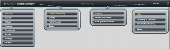
Figure 8-6 Management Interface Banner
Status and event indicators
Status and alert indicators occur at the bottom of each MI page. These indicators provide a quick status check for important cluster and grid properties. Grid indicators provide information for the entire grid. These indicators are displayed on the left and right corners of the page footer, and include tasks and events.
Figure 8-7 shows some examples of status and events that can be displayed from the Grid Summary panel. Also, notice the new function in the Management Interface introduced by R3.2 Licensed Internal Code (LIC), the Library Request command pane.
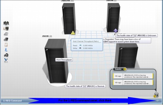
Figure 8-7 Status and Events indicators in the Grid Summary pane.
All cluster indicators provide information only for the accessing cluster, and are displayed only on MI pages that have a cluster scope. These three indicators occur in the middle of the page footer and include the following information:
•Physical Cache
•Copy Queues
•Health Status
Figure 8-8 shows a Cluster Summary pane, and some examples of status, events, and messages that can be seen in this page.

Figure 8-8 Cluster Summary pane and some information examples.
Management Interface also provides ways to filter, sort, and change the presentation of different tables in the MI. For example, you can hide or display a specific column, modify its size, sort the table results, or download the table row data in a comma-separated value (CSV) file to a local directory.
For a complete description of tasks, the behavior of health and status icons, and a description of how to optimize the table presentations, see the Using the Management Interface topic in the IBM Knowledge Center TS7700 3.2:
Library Request Command window
The LI REQ command pane in the Management Interface is a new capability introduced by R3.2 of the Licensed Internal Code, expanding the interaction of the System Administrator with the TS7700 subsystem. By using the LI REQ pane, a standard LI REQ command can be issued by the Storage Administrator directly from the Management Interface to a Grid (also known as Composite Library), or to a specific Cluster (also known as Distributed Library), with no need to be logged in to the z/OS host system.
The LI REQ pane is minimized and docked at the bottom of the MI panel. The user only has to click it (at the lower right end) to open up the LI REQ command pane. Figure 8-9 shows the new LI REQ command pane and operation.

Figure 8-9 LI REQ Command window and operation.
By default, the only user role allowed to issue LI REQ commands is the Administrator. LI REQ commands are logged in to tasks.
|
Remember: The LI REQ option only shows in the bottom of the Management Interface pages for users with the Administrator role.
|
Figure 8-10 shows an example of a library request command reported in the Tasks list, and shows how to get more information about the command by selecting Properties and See details in the MI page.

Figure 8-10 LI REQ command log and information
|
Important: LI REQ commands issued from this window are not presented in the host console logs.
|
For a complete list of available LI REQ commands, their usage, and respective responses, see the current IBM TS7700 Series z/OS Host Command Line Request User's Guide (WP101091), available in Techdocs:
Standard navigation elements
This section of the TS7700 Virtualization Engine MI provides you with functions to manage and monitor the health the TS7700 Virtualization Engine. Listed next are the expandable interface pages displayed on the left side of the MI Summary page. The exception is the systems interface page, which is displayed only when the cluster is part of a grid.
More items might also show, depending on the actual cluster configuration:
Systems icon This page shows the cluster members of the grid and grid-related functions.
Monitor icon This page gathers the events, tasks, and performance information about one cluster.
Light cartridge icon Information related to virtual volumes is available here.
Dark cartridge icon Information related to physical cartridges and the associated tape library are under this page.
Notepad icon In this page, you find the constructs settings.
Blue man icon Under the Access icon, you find all security-related settings.
Gear icon Cluster general settings, feature licenses, overrides, SNMP, write protect mode, and backup and restore settings under the Gear icon.
Tool icon Ownership takeover mode, network diagnostics, data collection, and other repair/recovery-related activities are under this icon.
MI Navigation
Use this window (Figure 8-11) for a visual summary of the IBM TS7700 Virtualization Engine MI Navigation.
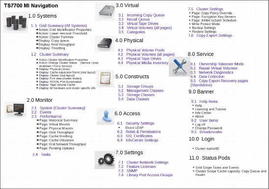
Figure 8-11 TS7700 Virtualization Engine MI Navigation
8.2.3 The Systems icon
The TS7700 Virtualization Engine MI windows gathered under the Systems icon can help to quickly identify cluster or grid properties, and assess the cluster or grid “health” at a glance.
|
Tip: The Systems icon is only visible when the accessed TS7700 Cluster is part of a grid.
|
Grid Summary page
The Grid Summary window is the first page displayed on the web interface when the IBM TS7700 Virtualization Engine is online. You can use this window to quickly assess the health of all clusters in the grid and as a starting point to investigate cluster or network issues.
|
Note: If the accessing cluster is a stand-alone cluster, the Cluster Summary window is shown upon login.
|
This window shows a summary view of the health of all clusters in the grid, including family associations, host throughput, and any incoming copy queue. Figure 8-12 shows an example of a Grid Summary window, including the pop-up windows.

Figure 8-12 Grid Summary and pop-up windows
Actions menu
Use this menu to change the appearance of clusters on the Grid Summary window or grid identification details. When the grid includes a TS7720 Virtualization Engine, you can also use this menu to change TS7720 Virtualization Engine removal threshold settings. See Figure 8-13 on page 305 for the Actions menu window. The following tasks are on this menu:
•Order by Cluster ID
Select this option to group clusters according to their cluster ID number. Ordered clusters are shown first from left to right, then front to back. Only one ordering option can be selected at a time.
|
Note: The number shown in parentheses in breadcrumb navigation and cluster labels is always the cluster ID.
|
•Order by Families
Select this option to group clusters according to their family association.
•Show Families
Select this option to show the defined families on the grid summary page. Cluster families are used to group clusters in the grid according to a common purpose.
•Cluster Families
Select this option to add, modify, or delete cluster families used in the grid.
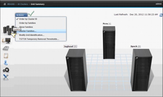
Figure 8-13 Grid Summary page and Actions
Cluster Families window
Use the window shown in Figure 8-14 to view information and run actions related to TS7700 Virtualization Engine cluster families.

Figure 8-14 MI Add Cluster Families window
Data transfer speeds between TS7700 Virtualization Engine clusters sometimes vary. The cluster family configuration groups clusters so that microcode can optimize grid connection performance between the grouped clusters.
To view or modify cluster family settings, first verify that these permissions are granted to your assigned user role. If your user role includes cluster family permissions, select Modify to run the following actions:
•Add a family: Click Add to create a new cluster family. A new cluster family placeholder is created to the right of any existing cluster families. Enter the name of the new cluster family in the active Name text box. Cluster family names must be 1 - 8 characters in length and composed of Unicode characters. Each family name must be unique. Clusters are added to the new cluster family by relocating a cluster from the Unassigned Clusters area using the method described in the Move a cluster function, described next.
•Move a cluster: You can move one or more clusters, by dragging, between existing cluster families, to a new cluster family from the Unassigned Clusters area, or to the Unassigned Clusters area from an existing cluster family:
– Select a cluster: A selected cluster is identified by its highlighted border. Select a cluster from its resident cluster family or the Unassigned Clusters area by using one of these methods:
• Clicking the cluster with your mouse.
• Using the Spacebar key on your keyboard.
• Pressing and holding the Shift key while selecting clusters to select multiple clusters at one time.
• Pressing the Tab key on your keyboard to switch between clusters before selecting one.
– Move the selected cluster or clusters:
• Clicking and holding the mouse on the cluster and drag the selected cluster to the destination cluster family or the Unassigned Clusters area.
• Using the arrow keys on your keyboard to move the selected cluster or clusters right or left.
|
Restriction: An existing cluster family cannot be moved within the Cluster Families window.
|
•Delete a family: You can delete an existing cluster family. Click the X in the upper-right corner of the cluster family you want to delete. If the cluster family that you attempt to delete contains any clusters, a warning message is displayed. Click OK to delete the cluster family and return its clusters to the Unassigned Clusters area. Click Cancel to abandon the delete action and retain the selected cluster family.
•Save changes: Click Save to save any changes made to the Cluster Families window and return it to read-only mode.
|
Remember: Each cluster family must contain at least one cluster. If you attempt to save changes and a cluster family does not contain any clusters, an error message displays and the Cluster Families window remains in edit mode.
|
Grid Identification properties window
Use the window shown in Figure 8-15 to view and alter identification properties for the TS7700 Virtualization Engine grid. In a multigrid environment, use this window to clearly identify a particular composite library, making it easier to distinguish, operate, and manage this TS7700 grid (avoiding operational mistakes due to ambiguous identification).
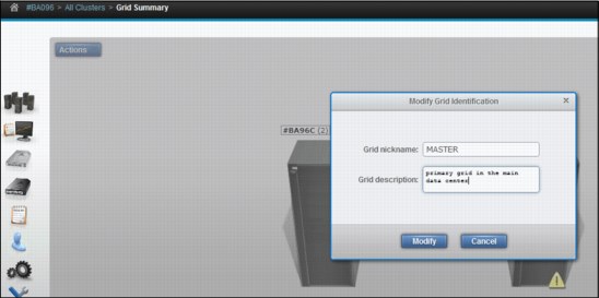
Figure 8-15 MI Grid Identification properties window
The following information, related to grid identification, is displayed. To change the grid identification properties, edit the available fields and click Modify. The following fields are available:
•Grid nickname: The grid nickname must be 1 - 8 characters in length and composed of alphanumeric characters with no spaces. The characters at (@), period (.), dash (-), and plus sign (+) are also allowed.
•Grid description: A short description of the grid. You can use up to 63 characters.
Lower removal threshold
Select TS7720 Temporary Removal Threshold from the Actions menu in the Grid summary view to lower the removal threshold for any TS7720 cluster in the grid. For more information about removal policies, see 4.2.5, “TS7720 cache thresholds and removal policies” on page 142.
Figure 8-16 shows the TS7720 Temporary Removal Threshold window.

Figure 8-16 TS7720 Temporary Removal Threshold
Grid health and details
In the Grid Summary view, cluster is in a normal state (healthy) when there is no warning or degradation icon displayed at the lower left side at the cluster’s representation in the Management Interface. Hovering the mouse pointer over the lower right corner of the cluster’s picture in the Grid Summary page shows The health state of the [cluster number] [cluster name] is Normal message, confirming that this cluster is in a normal state.
Exceptions in the cluster state are represented in the Grid Summary page by a little icon at the lower right side of the cluster’s picture. Use the main view of the Grid Summary window to compare the details and health status of all clusters in the grid. You can view additional information about the status by hovering over the icon with a mouse pointer.
Figure 8-17 on page 309 shows the appearance of the degraded icon, and the possible reasons for degradation to happen. The complete list of the icons and their meaning can be found at the TS7700 IBM Knowledge Center, which can be accessed straight from the Management Interface window by hovering over the question mark symbol at the right side of the banner, and clicking IBM Knowledge Center. Alternatively, the TS7700 3.2 IBM Knowledge Center is available at:

Figure 8-17 Warning or Degraded Icon meanings.
The following list includes the other possible statuses for a cluster that can be found in the Management Interface:
•Failed
•Service or Service Prep
•Unknown
•Offline
•Write Protect Mode
Figure 8-18 shows the icons.
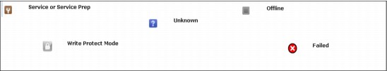
Figure 8-18 Other cluster status icons
Additional information can be obtained by hovering over the status icon with the mouse pointer.
See the IBM TS7700 3.2 IBM Knowledge Center, available locally at the Management Interface page by clicking the question mark icon at the right of the banner. For the complete list of icons and meanings, see the following website:
In the Grid Summary pane, there is an indicator meaning that throttling activity is occurring for a determined cluster within the grid. See Figure 8-19 for the visual reference of the throttling indicator. See Chapter 10, “Performance and monitoring” on page 597 for practical considerations on this topic, what it means, and what can be done to avoid it.

Figure 8-19 Clusters throttling in a two-cluster grid
Also see the IBM Virtualization Engine TS7700 Series Best Practices - Understanding, Monitoring and Tuning the TS7700 Performance white paper for an in-depth explanation of the throttling mechanism, where it is applied in the TS7700 and how it affects the subsystem performance:
Cluster Summary window
By clicking the icon of an individual cluster in the grid, or by selecting a specific cluster in the cluster navigation element in the banner, you can access the Cluster Summary window. When you are in a stand-alone configuration, this is the first icon available in the MI.
Figure 8-20 shows an example of the Cluster Summary window.

Figure 8-20 Cluster Summary window
In the Cluster Summary window, you can access the following options using the Actions menu:
•Modify Cluster Information
•Change Cluster State → Force Shut Down
•Change Cluster State → Service Prep
You also can display the Cluster Information by hovering the mouse over the components, as shown in Figure 8-20. In the resulting box, the following information is available:
•Cluster components health status
•Cluster Name
•Family to which this cluster is assigned
•Cluster model
•Licensed Internal Code (LIC) (Microcode) level for this cluster
•Description for this cluster
•Disk encryption status
•Cache size and occupancy (Cache Tube)
Cluster Actions menu
By using the options under this menu, the user can change the state or settings of a cluster. Also, when the selected cluster is a TS7740 or a TS7720T (a TS3500 Tape Library is present) this menu can be used to change the Copy Export settings.
From the Action menu, the Cluster State can be changed to a different one to perform a specific task, such as preparing for a maintenance window, performing a disaster recovery drill, or moving machines to a different IT center. Depending on the current cluster state, different options display.
Table 8-2 describes options available to change the state of a cluster.
Table 8-2 Options to change cluster state
|
If the current state is
|
You can select
|
Restrictions and notes
|
|
Online
|
Service Prep
|
All following conditions must first be met:
•The cluster is online.
•No other clusters in the grid are in service
prep mode. •At least one other cluster must remain online.
Caution: If only one other cluster remains online, a single point of failure exists when this cluster state becomes service prep mode.
Select Service Prep to confirm this change.
|
|
Force Shutdown
|
Select Force Shutdown to confirm this change.
Important: After a shutdown operation is initiated, it cannot be canceled.
|
|
|
Service Pending
|
Force Service
|
You can select this option if you think that an operation has stalled and is preventing the cluster from entering Service Prep.
Select Force Service to confirm this change.
Note: You can place all but one cluster in a grid into service mode but it is advised that only one cluster be in service mode at a time. If more than one cluster is in service mode, and you cancel service mode on one of them, that cluster does not return to normal operation until service mode is canceled on all clusters in the grid.
|
|
Return to Normal
|
You can select this option to cancel a previous service prep change and return the cluster to the normal online state.
Select Return to Normal to confirm this change.
|
|
|
Force Shutdown
|
Select Force Shutdown to confirm this change.
Important: After a shutdown operation is initiated, it cannot be canceled.
|
|
|
Shutdown (offline)
|
User interface not available
|
After an offline cluster is powered on, it attempts to return to normal. If no other clusters in the grid are available, you can skip hot token reconciliation.
|
|
Online-Pending or Shutdown Pending
|
Menu disabled
|
No options to change state are available when a cluster is in a pending state.
|
Going offline and coming online considerations
Whenever a member cluster of a grid goes offline or comes back online, it needs to exchange information with other peer members regarding the current status of the logical volumes controlled by the grid. Each logical volume is represented by a so-called token, which contains all of the pertinent information regarding that volume, such as creation date, whose cluster it belongs to, which cluster is supposed to have a copy of it, what kind of copy it should be, and so on.
Each cluster in the grid keeps its own copy of the collection of tokens, representing all the logical volumes existing in grid, and those copies are kept updated at the same level by the grid mechanism. When coming back online, a cluster needs to reconcile its own collection of tokens with the peer members of the grid, making sure that it represents the current status of the grid inventory. This reconcile operation is also referred to as token merge.
•Pending token merge
A cluster in a grid configuration attempts to merge its token information with all of the other clusters in the grid as it goes online. When no other clusters are available for this merge operation, the cluster attempting to go online remains in the going online, or blocked, state indefinitely as it waits for the other clusters to become available for the merge operation. If a pending merge operation is preventing the cluster from coming online, you are given the option to skip the merge step.
Click Skip Step to skip the merge operation. This button is only available if the cluster is in a blocked state waiting to share pending updates with one or more unavailable clusters. If you click Skip Step, pending updates against the local cluster might remain undetected until the unavailable clusters become available.
•Ownership takeover
If ownership takeover was set at any of the peers, the possibility exists that old data can surface to the host if the cluster is forced online. Therefore, before attempting to force this cluster online, it is important to know whether any peer clusters have ever enabled ownership takeover mode against this cluster while it was unavailable. In addition, if this cluster is in service, automatic ownership takeover from unavailable peers is also likely and must be considered before attempting to force this cluster online.
If multiple clusters have been offline and must be forced back online, force them back online in the reverse order that they went down in (for example, the last cluster down is the first cluster up). This process ensures that the most current cluster is available first to educate the rest of the clusters forced online.
•Autonomic Ownership Takeover Manager (AOTM)
If it is installed and configured, it attempts to determine whether all unavailable peer clusters are actually in a failed state. If it determines that the unavailable cluster is not in a failed state, it blocks an attempt to force the cluster online. If the unavailable cluster is not in a failed state, the forced online cluster can be taking ownership of volumes that it must not take ownership of. If AOTM discovers that all unavailable peers have failed and network issues are not to blame, this cluster is then forced into an online state.
After it is online, AOTM can further enable ownership takeover against the unavailable clusters if the AOTM option is enabled. Additionally, manual ownership takeover can be enabled, if necessary.
•Shutdown restrictions
You can shut down only the cluster into which you are logged. To shut down another cluster, you must log out of the current cluster and log in to the cluster that you want to shut down. See “Cluster Shutdown window” on page 316 for more details about this topic.
|
Note: After a shutdown or force shutdown action, the targeted cluster (and associated cache) are powered off. A manual intervention is required on site where the cluster is physically located to power it up again.
|
A cluster shutdown operation started from the TS7700 Virtualization Engine MI also shuts down the cache. The cache must be restarted before any attempt is made to restart the TS7700 Virtualization Engine.
Service mode window
Use the window shown in Figure 8-21 to put a TS7700 Virtualization Engine Cluster into service mode, whenever required by a service action or any disruptive activity on a cluster that is a member of a grid. See Chapter 2, “Architecture, components, and functional characteristics” on page 13 for more information.
|
Remember: Service mode is only possible for clusters that are members of a grid.
|

Figure 8-21 TS7700 MI for service preparation
Service mode enables the subject cluster to leave the grid graciously, surrendering the ownership of its logical volumes as required by the peer clusters in the grid to attend to the tasks being performed by client. The operation continues smoothly in the other members of the grid, automatically, because consistent copy volumes in this cluster exist elsewhere in the grid. Before changing a cluster state to Service, the user needs to vary offline all logical drives associated to this cluster. No host access is available in a cluster that is in service mode.
|
Important: Forcing Service Mode causes jobs currently mounted or using resources provided by targeted cluster to fail.
|
Whenever a cluster state is changed to Service, it enters first in service preparation mode, and then, when the preparation stage finishes, it goes automatically into service mode.
During the service preparation stage, the cluster monitors the status of current host mounts, sync copy mounts targeting local TVC, monitors and finishes up the copies that are currently in execution, and makes sure that there are no remote mounts targeting local TVC. When all running tasks have ended, and no more pending activities are detected, the cluster finishes service preparation stage and enters Service mode.
In a TS7700 Virtualization Engine Grid, service prep can occur on only one cluster at any one time. If service prep is attempted on a second cluster at the same time, the attempt fails. After service prep has completed for one cluster and that cluster is in service mode, another cluster can be placed in service prep. A cluster in service prep automatically cancels service prep if its peer in the grid experiences an unexpected outage while the service prep process is
still active.
still active.
|
Consideration: Although you can place all clusters except one in service mode, the best approach is having only one cluster in service mode at a time. If more than one cluster is in service mode, and you cancel service mode on one of them, that cluster does not return to online state until service mode is canceled on all the clusters.
|
For a TS7720 Virtualization Engine cluster in a grid, you can click Lower Threshold to lower the required threshold at which logical volumes are removed from cache in advance. See “Temporary Removal Threshold” on page 145 for more information about the Temporary Removal Threshold. The following items are available when viewing the current operational mode of a cluster.
Cluster State can be any of the following states:
•Normal: The cluster is in a normal operation state. Service prep can be initiated on this cluster.
•Service Prep: The cluster is preparing to go into service mode. The cluster is completing operations (that is, copies owed to other clusters, ownership transfers, and lengthy tasks, such as inserts and token reconciliation) that require all clusters to be synchronized.
•Service: The cluster is in service mode. The cluster is normally taken offline in this mode for service actions or to activate new code levels.
Depending on the mode that the cluster is in, a different action is presented by the button under the Cluster State display. You can use this button to place the TS7700 Virtualization Engine into service mode or back into normal mode:
•Prepare for Service Mode: This option puts the cluster into service prep mode and enables the cluster to finish all current operations. If allowed to finish service prep, the cluster enters service mode. This option is only available when the cluster is in normal mode. To cancel service prep mode, click Return to Normal Mode.
•Return to Normal Mode: Returns the cluster to normal mode. This option is available if the cluster is in service prep or service mode. A cluster in service prep mode or service mode returns to normal mode if Return to Normal Mode is selected.
You are prompted to confirm your decision to change the Cluster State. Click Service Prep or Normal Mode to change to new Cluster State, or Cancel to abandon the change operation.
Cluster Shutdown window
Use the window shown in Figure 8-22 to remotely shut down a TS7700 Virtualization Engine Cluster for a planned power outage or in an emergency.

Figure 8-22 MI Cluster shutdown window
This window is visible from the TS7700 Virtualization Engine MI whether the TS7700 Virtualization Engine is online or in service. If the cluster is offline, MI is not available, and the error HYDME0504E The cluster you selected is unavailable is presented.
|
Note: After a shutdown or force shutdown action, the targeted cluster (and associated cache) are powered off. A manual intervention is required on site where cluster is physically located to power it up again.
|
You can shut down only the cluster to which you are logged in. To shut down another cluster, you must log out of the current cluster and log in to the cluster that you want to shut down.
Before you shut down the TS7700 Virtualization Engine, you must decide whether your circumstances provide adequate time to perform a clean shutdown. A clean shutdown is not mandatory, but it is suggested for members of a TS7700 grid configuration. A clean shutdown requires you to first put the cluster in service mode to ensure that no jobs or copies are targeting or being sourced from this cluster during shutdown.
Jobs using this specific cluster are affected, but also copies are cancelled. Eligible data, which has not been copied yet to remaining clusters cannot be processed accordingly during service and downtime. If you cannot place the cluster in service mode, you can use the force shutdown option.
|
Attention: A forced shutdown can result in lost access to data and job failure.
|
A cluster shutdown operation that is started from the TS7700 Virtualization Engine MI also shuts down the cache. The cache must be restarted before any attempt is made to restart the TS7700 Virtualization Engine.
If you select Shutdown from the action menu for a cluster that is still online, as shown at the top of Figure 8-22 on page 316, a message alerts you to first put the cluster in service mode before shutting down as shown in Figure 8-23.

Figure 8-23 Warning message and Cluster Status
In Figure 8-23, the Online State and Service State fields in the message show the operational status of the TS7700 Virtualization Engine and appear over the button that is used to force its shutdown. The lower-right corner of the picture shows the cluster status reported by the message. You have the following options:
•Cluster State. The following values are possible:
– Normal. The cluster is in an online, operational state and is part of a TS7700 Virtualization Engine Grid.
– Service. The cluster is in service mode or is a stand-alone system.
– Offline. The cluster is offline. It might be shutting down in preparation for service mode.
•Shutdown. This button initiates a shutdown operation:
– Clicking Shutdown in Normal mode. If you click Shutdown while in normal mode, you receive a warning message suggesting that you place the cluster in service mode before proceeding, as shown in Figure 8-23 on page 317. To place the cluster in service mode, select Modify Service Mode. To continue with the force shutdown operation, provide your password and click Force Shutdown. To abandon the shutdown operation, click Cancel.
– Clicking Shutdown in Service mode. If you select Shutdown while in service mode, you are asked to confirm your decision. Click Shutdown to continue, or click Cancel to abandon the shutdown operation.
|
Important: After a shutdown operation is initiated, it cannot be canceled.
|
When a shutdown operation is in progress, the Shutdown button is disabled and the status
of the operation is displayed in an information message. The following list shows the shutdown sequence:
of the operation is displayed in an information message. The following list shows the shutdown sequence:
1. Going offline
2. Shutting down
3. Powering off
4. Shutdown completes
Verify that power to the TS7700 Virtualization Engine and to the cache is shut down before attempting to restart the system.
A cluster shutdown operation started from the TS7700 Virtualization Engine MI also shuts down the cache. The cache must be restarted first and allowed to achieve an operational state before any attempt is made to restart the TS7700 Virtualization Engine.
Cluster Identification Properties window
Use the window shown in Figure 8-24 to view and alter cluster identification properties for the TS7700 Virtualization Engine. This can be used to distinguish this distributed library.

Figure 8-24 MI Cluster Identification properties window
The following information related to cluster identification is displayed. To change the cluster identification properties, edit the available fields and click Modify. The following fields are available:
•Cluster nickname: The cluster nickname must be 1 - 8 characters in length and composed of alphanumeric characters. Blank spaces and the characters at (@), period (.), dash (-), and plus sign (+) are also allowed. Blank spaces cannot be used in the first or last character position.
•Cluster description: A short description of the cluster. You can use up to 63 characters.
Cluster health and detail
The health of the system is checked and updated automatically from time to time by the TS7700 Virtualization Engine. The information status reflected on this page is not in real time; it shows the status of the last check-out. To repopulate the summary window with the updated health status, click the Refresh icon. This operation takes some minutes to complete. If this cluster is operating in Write Protect Mode, a lock icon is shown in the middle right part of the cluster image.
See Figure 8-25 for reference. In the cluster front view, you see a general description about the cluster, such as model, name, family, microcode level, cluster description, and cache encryption capabilities right in the cluster badge (top of the box picture).
Hovering the cursor over the locations within the picture of the frame shows you the health status of different components, such as the network gear (at the top), Tape Volume Cache (TVC) controller and expansion enclosures (bottom and halfway up), and the engine server along with the internal 3957-Vxx disks (the middle). The summary of cluster health shows at the lower-right status bar, and also at the badge health status (over the frame).
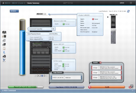
Figure 8-25 Front view of Cluster Summary with health details
The new R3.2 of Licensed Internal Code for the Management Interface improves the information provided by the element health information. Note the information now available in the example shown in Figure 8-20 on page 311 for a healthy cluster. Figure 8-26 shows another example of the enhanced information by the R3.2 MI, detailing a failed DDM in a 3956-CC7 Cache Controller.
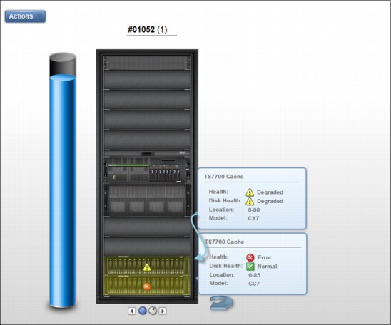
Figure 8-26 Sample of a degraded 3957-CC7 with a failed DDM in R3.2
Figure 8-27 an example of the cache tube display in a multi-partitioned TS7720T (Tape Attach), introduced in R3.2 of Licensed Internal Code:
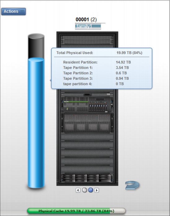
Figure 8-27 Display of the Cache tube in a multi-partitioned TS7720T
Figure 8-28 on page 322 shows the back view of the cluster summary window and health details. The components depicted in the back view are the Ethernet ports and host Fibre Channel connection (FICON) adapters for this cluster. Under the Ethernet tab, you can see the ports dedicated to the internal network (the TSSC network) and those dedicated to the external (client) network.
You can see the assigned IP addresses, if IPv4 or IPv6, that are being used, and the health of the ports are shown for those ports. In the grid Ethernet ports, information about links to the other clusters, data rates, and cyclic redundancy check (CRC) errors are displayed for each port in addition to the assigned IP address and Media Access Control (MAC) address.
The host FICON adapter information is displayed under the Fibre tab for a selected cluster, as shown in Figure 8-28. The available information includes the adapter position and general health for each port.
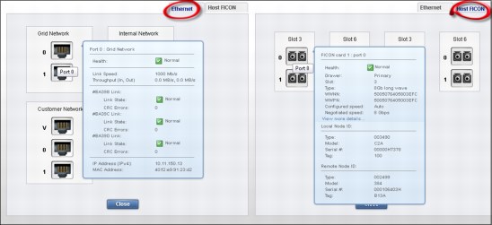
Figure 8-28 Back view of the cluster summary with health details
To display the different area health details, hover the cursor over the component in the picture.
Cache expansion frame
The expansion frame view displays details and health for a cache expansion frame attached to the TS7720 Cluster. To open the expansion frame view, click the small image corresponding to a specific expansion frame, beneath the Actions button.
|
Tip: The expansion frame icon is only displayed if the accessed cluster has an expansion frame.
|
See Figure 8-29 for a visual reference of the Cache Expansion frame details and health view through the Management Interface.
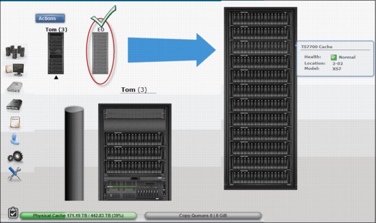
Figure 8-29 Cache expansion frame details and health
Physical library and tape drive health
The Physical Library icon, visible in a TS7740 and TS7720T Cluster Summary window, enables you to check the health of the tape library and tape drives by clicking it. See Figure 8-30.
Also, clicking the TS3500 Tape Library Expanded picture opens the TS3500 Library Specialist web interface.
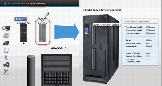
Figure 8-30 TS3500 Tape Library Expanded from Cluster Summary page
|
Restriction: If the cluster is not a TS7740 or a TS7720T, the Tape Library icon does not display on the TS7700 Virtualization Engine MI.
|
The library details and health are displayed as explained in Table 8-3.
Table 8-3 Library health details
|
Detail
|
Definition
|
|||
|
Physical library type - virtual library name
|
The type of physical library (type is always TS3500) accompanied by the name of the virtual library established on the physical library.
|
|||
|
Tape Library Health
Fibre Switch Health
Tape Drive Health
|
The health states of the library and its main components. The following values are possible:
•Normal
•Degraded
•Failed
•Unknown
|
|||
|
State
|
Whether the library is online or offline to the TS7700 Virtualization Engine.
|
|||
|
Operational Mode
|
The library operational mode. The following values are possible:
•Auto
•Paused
|
|||
|
Frame Door
|
Whether a frame door is open or closed.
|
|||
|
Virtual I/O Slots
|
Status of the I/O station used to move cartridges into and out of the library. The following values are possible:
•Occupied
•Full
•Empty
|
|||
|
Physical Cartridges
|
The number of physical cartridges assigned to the identified virtual library.
|
|||
|
Tape Drives
|
The number of physical tape drives available, as a fraction of the total. Click this detail to open the Physical Tape Drives window.
|
|||
From the TS3500 Tape Library Expanded page, you can open the Physical Tape Drives window. Click the Tape Drives item in the health report, as shown in Figure 8-31.

Figure 8-31 Opening the Physical Tape Drives window
The Physical Tape Drives window looks similar to the example in Figure 8-32.

Figure 8-32 Physical Tape Drives window
On the Physical Tape Drives window, you see all the specific details about a physical tape drive, such as its serial number, drive type, whether the drive has a cartridge mount on it, what is it mounted for, among others. To see the same information, such as drive encryption, tape library location, and so on, about the other tape drives, select a specific drive and choose Details in the Select Action menu. The detailed drive information window is shown in Figure 8-33.

Figure 8-33 Physical Tape Drive Details and navigation
8.2.4 The Monitor icon
The collection of pages under the Monitor icon in the MI enables7 you to monitor events in the TS7700 Virtualization Engine.
Events encompass every significant occurrence within the TS7700 Virtualization Grid or Cluster, such as a malfunctioning alert, an operator intervention, a parameter change, a warning message, or some user-initiated action. Figure 8-34 shows the Monitor icon in a grid and in a stand-alone cluster.

Figure 8-34 Monitor icon in a grid or stand-alone configuration
|
Tip: Notice in Figure 8-34 that the Systems icon only shows up in a grid configuration, and the Cluster Summary item only shows up under Monitor in a stand-alone configuration.
|
Events
Use this window, shown in Figure 8-35, to view all meaningful events that occurred within the grid or a stand-alone TS7700 Virtualization Engine Cluster.
You have the choice to send future events to the host operational system, by enabling host notification. Although events are grid-wide, enabling or disabling host notification only affects the currently accessed cluster when in a grid configuration. Also, task events are not sent to the host.
Information is displayed on the Events table for 30 days after the operation stops or the event becomes inactive.
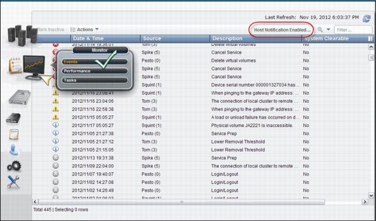
Figure 8-35 TS7700 Management Interface Events window
|
Note: The Date & Time column refers the time of the events to the local time in the computer where the Management Interface was initiated. If the DATA/TIME has been modified in the TS7700 from Coordinated Universal Time during installation, the event times are offset by the same difference in the Events display on the Management Interface. We suggest using Coordinated Universal Time in all TS7700 clusters when possible.
|
Figure 8-36 shows the alerts, tasks, and event values and associated severity icons in the Events window in the MI.

Figure 8-36 Alerts, tasks, and event values and associated severity icons
Table 8-4 describes the column names and descriptions of the fields, as shown in the Event window (see Figure 8-35 on page 327).
Table 8-4 Field name and description for the Events window
|
Column name
|
Description
|
|||
|
Date & Time
|
Date and time the event occurred.
|
|||
|
Source
|
Cluster where the event occurred.
|
|||
|
Location
|
Specific location on the cluster where the event occurred.
|
|||
|
Description
|
Description of the event.
|
|||
|
ID
|
The unique number that identifies the instance of the event. This number consists of the following values:
•A locally generated ID, for example: 923
•The type of event: E (event) or T (task)
An event ID based on these examples appears as 923E.
|
|||
|
Status
|
The status of an alert or task.
If the event is an alert, this value is a fix procedure to be performed or the status of a call home operation.
If the event is a task, this value is its progress or one of these final status categories:
•Canceled
•Canceling
•Completed
•Completed, with information
•Completed, with warning
•Failed
|
|||
|
System Clearable
|
Whether the event can be cleared automatically by the system. The following values are possible:
Yes. The event is cleared automatically by the system when the condition causing the event has been resolved.
No. The event requires user intervention to clear. You must clear or deactivate the event manually after resolving the condition causing the event.
|
|||
Table 8-5 lists actions that can be run on the Events table.
Table 8-5 Actions that can be run on the Events table
|
To run this task
|
Action
|
|||
|
Deactivate or clear one or more alerts
|
1. Select at least one but no more than 10 events.
2. Click Mark Inactive.
If a selected event is normally cleared by the system, you must confirm your selection. Other selected events are cleared immediately.
Note: You can clear a running task but if the task later fails, it is displayed again as an active event.
|
|||
|
Enable or disable host notification for alerts
|
Select Actions → [Enable/Disable] Host Notification. This change affects only the accessing cluster.
Note: Tasks are not sent to the host.
|
|||
|
View a fix procedure for an alert
|
Select Actions → View Fix Procedure.
Note: A fix procedure can be shown for only one alert at a time. No fix procedures are shown for tasks.
|
|||
|
Download a comma-separated value (CSV) file of the events list
|
Select Actions → Download all Events.
|
|||
|
View more details for a selected event
|
1. Select an event.
2. Select Actions → Properties.
|
|||
|
Hide or show columns on the table
|
1. Right-click the table header.
2. Click the check box next to a column heading to hide or show that column in the table. Column headings that are checked display on the table.
|
|||
|
Filter the table data
|
Follow these steps to filter by using a string of text:
1. Click in the Filter field.
2. Enter a search string.
3. Press Enter.
To filter by column heading:
1. Click the down arrow next to the Filter field.
2. Select the column heading to filter by.
3. Refine the selection.
|
|||
|
Reset the table to its default view
|
1. Right-click the table header.
2. Click Reset Table Preferences.
|
|||
8.2.5 Performance
This section introduces the performance and statistic windows available in the TS7700 Virtualization Engine MI.
All graphical views, except the Historical Summary, are from the last 15 minutes. The Historical Summary presents a customized graphical view of the different aspects of the cluster operation, in a 24-hour time frame. This 24-hour window can be slid back up to 90 days, which covers three months of operations.
Historical Summary
Figure 8-37 shows the Throughput View for the Historical Summary in Monitor → Performance Management Interface operation in a TS7720T cluster.

Figure 8-37 Performance window operation, Throughput view
Release R3.2 enhances the Performance window in Management Interface to accommodate the new functions introduced by the new code. Figure 8-38 shows the Performance Historical Summary and related chart selections available for this item.

Figure 8-38 Performance options and chart selections
Figure 8-39 shows another Historical Summary sample from the same cluster, selecting the Throttling view. The performance data came from a TS7720T (tape attach) cluster.
Notice that the chart shows in orange the information about the host throttling applied to the resident partition (CP0), where the brown line represents the host write throttling values applied to the tape-attached partitions (CP1 - CP7). Because all tape attached partition feeds into the same premigration queue, sharing the same physical tape drive resources, they all are equally affected by the same host throttling value.

Figure 8-39 Historical Summary showing the Throttling view for a stand-alone TS7720T
Clicking the Download Spreadsheet icon shown on the left of Figure 8-39 saves the raw data for the graph in a comma-separated value (CSV) file. Downloadable data is also limited to a 24-hour period from the start date and time defined in the window.
By using the Select Metrics icon, the user is able to select up to 10 data sets of different statistics to populate the chart depending on what aspect of cluster’s performance is under scrutiny. The Select Metrics window is shown (not all options in the picture) in Figure 8-40.
|
Note: Up to ten different statistic data sets can be selected for the same graph view.
|

Figure 8-40 Select Metrics window
See Chapter 10, “Performance and monitoring” on page 597 for an explanation of the values and what to expect in the resulting graphs. Also, see the TS7700 3.2 IBM Knowledge Center for a complete description of the page and available settings. The TS7700 3.2 IBM Knowledge Center is available both locally on the TS7700 MI (by clicking the question mark icon at the upper right corner of the page) and on the following website:
Also, see IBM Virtualization Engine TS7700 Series Best Practices - Understanding, Monitoring, and Tuning the TS7700 Performance, WP101465, which is available on the IBM Techdocs Library website:
The WP101465 paper is an in-depth study of the inner workings of the TS7700, and the factors that can affect the overall performance of a stand-alone cluster or a TS7700 grid. Also, it explains throttling mechanisms and available tuning options for the subsystem to achieve peak performance.
Virtual Mounts
The Virtual Mounts statistics for the last 15 minutes of activity are displayed in a bar graphs and table format per cluster. Figure 8-41 shows an example of a virtual mounts graph for a TS7720T cluster.
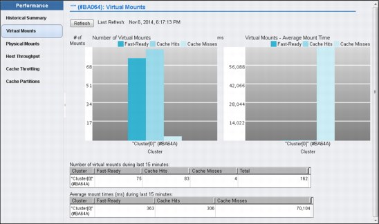
Figure 8-41 Virtual Mounts performance window.
In a grid configuration, the Virtual Mounts chart displays the activity for all members in the grid. See the TS7700 Customer Information for more details.
Physical Mounts
The Physical Mounts statistics for the last 15 minutes of activity will be displayed in a bar graphs and table format per cluster. This page will be available and active when the selected TS7700 is attached to a physical tape library (TS7740 or TS7720T). When a grid possesses a physical library but the selected cluster does not, MI displays the following message:
The cluster is not attached to a physical tape library.
This page is not visible on the TS7700 Management Interface if the grid does not possess a physical library (no tape attached member).
Figure 8-42 shows an example of a physical mounts page for a four-cluster grid.

Figure 8-42 Physical mounts statistic display
Host Throughput
The host throughput for data transfer activity is shown for the last 15 minutes in a bar graph and tables. The throughput is shown for all clusters in a grid. Figure 8-43 shows the Host Throughput page in MI.
Notice the hyperlink, which enables the user to single out the throughput numbers of a specific host adapter in a specific cluster for a deeper look.

Figure 8-43 the Host Throughput page
See the TS7700 3.2 IBM Knowledge Center for a complete description of the page.
The TS7700 3.2 IBM Knowledge Center is available both locally at TS7700 MI (by clicking the question mark icon at the upper right corner of the page) and on the following website:
Cache Throttling
This page shows the statistics of the throttling values applied on the host write operations and RUN copy operations throughout the grid.
Figure 8-44 is an example of the Cache Throttling page.
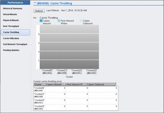
Figure 8-44 Cache Throttling page
See the TS7700 3.2 IBM Knowledge Center for a complete description of the page, either locally at TS7700 MI (by clicking the question mark icon at the upper right corner of the page) or on the following website:
Cache Utilization
Cache utilization statistics are presented for clusters having one resident-only or tape-only partition, and for clusters with partitioned cache. Models TS7720 and TS7740 only have one resident or tape partition, which accounts for the entire cache. The cache partitioning concept, and the TS7720T cluster model, were introduced in Release 3.2 of Licensed Internal Code.
Figure 8-45 on page 337 shows an example of Cache Utilization (single partition), as displayed in a TS7720 disk only or TS7740 cluster.

Figure 8-45 TS7720 or TS7740 Cache Utilization page.
Cache Partition
The Cache Partition page presents the cache use statistics for the TS7720T model, in which the cache is made up of multiple partitions. Figure 8-46 shows a sample of the Cache Partition (multiple partitions) page. This page can be reached using the Monitor icon (as described here) or using the Virtual icon. Both ways direct you to the same page. In this page, the user can display the already existent cache partitions, but also can create a new partition, reconfigure an existing one, or delete a partition as needed.
|
Tip: Consider limiting the Management Interface user roles who are allowed to change the partition configurations through this page.
|
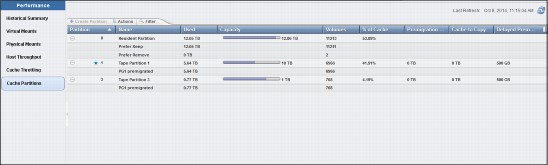
Figure 8-46 Cache Partitions page
See the TS7700 IBM Knowledge Center for a complete description of the page, either locally on the TS7700 MI (by clicking the question mark icon) or on the following website:
Grid Network Throughput
This page is only available if the TS7700 cluster is a member of a Grid. The Grid Network Throughput page shows the last 15 minutes of cross-cluster data transfer rate statistics, shown in megabytes per second (MBps). Each cluster of the grid is represented both in the bar graph chart and in the tables. Figure 8-47 shows an example of the Grid Network Throughput page.

Figure 8-47 Grid Network Throughput page
See the TS7700 3.2 IBM Knowledge Center for more details about this page. Learn about data flow within the grid and how those numbers vary during the operation in Chapter 10, “Performance and monitoring” on page 597.
Pending Updates
The Pending Updates window is only available if the TS7700 cluster is a member of a grid. Pending updates window can be used to monitor status of outstanding updates per cluster throughout the grid. Pending updates can be caused by one cluster being offline, in service preparation or service mode while other grid peers were busy with the normal client’s production work.
A faulty grid link communication also might cause a RUN or SYNC copy to became Deferred Run or Sync. The Pending Updates window can be used to follow the progress of those copies. Figure 8-48 on page 339 shows a sample of Pending Updates window.
The Download bottom in the top of the page saves a comma-separated value (.CSV) file listing all volumes or grid global lock targeted during an ownership takeover. The volume or global pending updates are listed, along with hot tokens and stolen volumes.
Tokens are internal data structures that are used to track changes to the ownership, data, or properties of each one of the existing logical volumes in the grid. Hot tokens occur when a cluster attempts to merge its own token information with the other clusters, but the clusters are not available for the merge operation.
Stolen volume describes a volume whose ownership has been taken over during a period in which the owner cluster was in service mode or offline. Also, in the case of an unexpected cluster outage, when the volume ownership has been taken over under an operator’s direction, or by using AOTM (Autonomic Ownership Takeover Manager).

Figure 8-48 Pending Updates page.
See Chapter 2, “Architecture, components, and functional characteristics” on page 13 for more information regarding copy mode and other concepts referred to in this section. Also, see TS7700 3.2 IBM Knowledge Center for other information about this MI function on the following website:
Tasks window
This page is used to monitor the status of tasks submitted to the TS7700 Virtualization Engine. You can find information for an entire grid if the accessing cluster is part of a grid, or only for this individual cluster if it is a stand-alone configuration. You can format the table by using filters, or you can reset the table format to its default by using reset table preferences. Information is available in the task table for 30 days after the operation stops or the event or action becomes inactive.
Tasks are listed by starting date and time. Tasks that are still running are shown on the top of the table, and the completed tasks are listed at the bottom. Figure 8-49 shows an example of the Tasks window.

Figure 8-49 Tasks window
|
Note: The Start Time column refers to the time of starting a task to the local time on the computer where the Management Interface was started. If the DATA/TIME has been modified in the TS7700 from Coordinated Universal Time during installation, the task start times are offset by the same difference in the Tasks display on the MI. Use Coordinated Universal Time in all TS7700 clusters unless you have a good reason not to.
|
8.2.6 The Virtual icon
TS7700 Virtualization Engine MI pages collected under the Virtual icon can help you view or change settings related to virtual volumes and their queues, virtual drives, and scratch (Fast Ready) categories. Release 3.2 of Licensed Internal Code introduces the TS7720T (Tape Attach). For the TS7720T a new item, Cache Partitions, has been added under the Virtual icon, which enables the user to create, modify, or delete cache partitions.
Figure 8-50 shows the Virtual icon and the options available both for TS7720T and the traditional models.
The Cache Partitions item only is available for the TS7720T models, while the Incoming Copy Queue item shows only in grid configurations.

Figure 8-50 The Virtual icon and options
The available items under the Virtual icon are described in the following topics.
Cache Partitions
Cache utilization, multiple partitions is the page available in Management Interface to create a new cache partition, or reconfigure or delete an existing cache partition. Cache partitioning is introduced with R3.2 of Licensed Internal Code for the new TS7720T models. Also, the same page enables the user to monitor the cache and partitions occupancy and usage. Figure 8-51 shows a Cache Partitions screen capture.
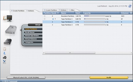
Figure 8-51 Cache Partitions page in Management Interface
Figure 8-52 on page 343 shows a sequence for creating a new partition. There can be as many as eight partitions, from Resident partition (partition 0) to Tape Partition 7, if needed. The tape partition allocated size is subtracted from the actual resident partition capacity, if there is at least more than 2 TB of free space in the resident partition (CP0). See the TS7700 3.2 IBM Knowledge Center for the complete set of rules and allowed values in effect for this page. Also, learn about the TS7720T, cache partitions, and usage in Chapter 2, “Architecture, components, and functional characteristics” on page 13.
|
Restrictions: No new partition can be created if Resident-Only (CP0) has 2 TB or less of free space. Creation of new partitions is blocked by a Flash Copy for DR in progress, or by one of the existing partitions being in overcommitted state.
|
Figure 8-52 illustrates creating a new partition.
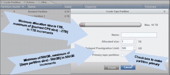
Figure 8-52 Creating a new Tape Partition
Figure 8-53 show an example of successful creation in the upper half. In the lower half, an example where the user failed to observe the amount of free space available in CP0.

Figure 8-53 Example of success and a failure to create a new partition.
Notice that redefining the size of existing partitions in an operational TS7720T might create unexpected load peak in the overall premigration queue, causing host write throttling to be applied to the tape partitions.
For instance, consider the following example, where a tape attached partition is downsized, and become instantly overcommitted. In this example, the TS7720T premigration queue is flooded by volumes that got dislodged by the size of this cache partition becoming smaller. Partition readapts to the new size by migrating volumes in excess to physical tape.
Figure 8-54 shows the previous scenario, TS7720T operating and Tape Partition 1 operating with 12 TB cache.

Figure 8-54 Tape partition 1 operating with 12TB Cache.
Figure 8-55 shows tape partition 1 being downsized to 8 TB. Note the initial warning and subsequent overcommit statement that shows up when resizing the tape partition results in overcommitted cache size.

Figure 8-55 Downsizing Tape Partition 1, and the overcommit warning.
Accepting the Overcommit statement initiates the resizing action. If this is not the best-suited time for the partition resizing (as during the peak load period), the user can click No and decline to take the action, and then resume it at a more appropriate time. Figure 8-56 shows the final sequence of the operation.

Figure 8-56 Resizing message and resulting cache partitions window
Read more about this subject in Chapter 10, “Performance and monitoring” on page 597 and Chapter 2, “Architecture, components, and functional characteristics” on page 13.
|
Tip: Consider limiting the Management Interface user roles that are allowed to change the partition configurations through this page.
|
Incoming copy queue
The Incoming copy queue page is displayed for a grid-member TS7700 cluster. Use this page to view the virtual volume incoming copy queue for an IBM TS7700 Virtualization Engine cluster. The incoming copy queue represents the amount of data waiting to be copied to a cluster. Data written to a cluster in one location can be copied to other clusters in a grid to achieve uninterrupted data access.
You can specify on which clusters (if any) copies are, and how quickly copy operations occur. Each cluster maintains its own list of copies to acquire, and then satisfies that list by requesting copies from other clusters in the grid according to queue priority.
Table 8-6 shows the values displayed in the copy queue table.
Table 8-6 Values in the copy queue table
|
Column type
|
Description
|
|||
|
Copy Type
|
The type of copy that is in the queue. The following values are possible:
•Immediate: Volumes can be in this queue if they are assigned to a Management Class that uses the Rewind Unload (RUN) copy mode.
•Synchronous-deferred: Volumes can be in this queue if they are assigned to a Management Class that uses the Synchronous mode copy and some event (such as the secondary cluster going offline) prevented the secondary copy from occurring.
•Immediate-deferred: Volumes can be in this queue if they are assigned to a Management Class that uses the RUN copy mode and some event (such as the secondary cluster going offline) prevented the immediate copy from occurring.
•Deferred: Volumes can be in this queue if they are assigned to a Management Class that uses the Deferred copy mode.
•Time Delayed: Volumes can be in this queue if they are eligible to be copied based on either their creation time or last access time.
•Copy-refresh: Volumes can be in this queue if the Management Class assigned to the volumes has changed and a LI REQ command was sent from the host to initiate a copy.
•Family-deferred: Volumes can be in this queue if they are assigned to a Management Class that uses RUN or Deferred copy mode and cluster families are being used.
|
|||
|
Last TVC Cluster
|
The name of the cluster where the copy last was in the TVC. Although this might not be the cluster from which the copy is received, most copies are typically obtained from the TVC cluster.
Note: This column is only shown when View by Last TVC is selected.
|
|||
|
Size
|
Total size of the queue, displayed in GiB.
Note: See 1.5, “Data storage values” on page 12 for additional information about the use of binary prefixes.
When Copy Type is selected, this value is per copy type. When View by Last TVC is selected, this value is per cluster.
|
|||
|
Quantity
|
The total number of copies in queue for each type.
|
|||
Figure 8-57 shows the incoming copy queue page and other places in the Grid Summary and Cluster Summary that inform the user about the current copy queue for a specific cluster.

Figure 8-57 Incoming copy queue
Using the upper-left option, you can choose between View by Type and View by Last TVC Cluster. The Actions menu enables you to download the Incoming Queued Volumes list.
Recall queue
The Recall Queue window of the MI displays the list of virtual volumes in the recall queue. You can use this window to promote a virtual volume or filter the contents of the table. The Recall Queue item is visible but disabled on the TS7700 Virtualization Engine MI if there is no physical tape attachment to the selected cluster, but there is at least one tape attached cluster (TS7740 or TS7720T, which are connected to a TS3500 Tape Library) within the grid. Trying to access the Recall queue link from a cluster with no tape attachment causes the following message to display:
The cluster is not attached to a physical tape library.
|
Tip: This item is not visible on the TS7700 Virtualization Engine MI if there is no TS7740 or TS7720T cluster in grid.
|
A recall of a virtual volume retrieves the virtual volume from a physical cartridge and places it in the cache. A queue is used to process these requests. Virtual volumes in the queue are classified into three groups:
•In Progress
•Scheduled
•Unscheduled
Figure 8-58 shows an example of the Recall queue window.

Figure 8-58 Recall queue window
Table 8-7 shows the names and the descriptions of the values that might be seen on the Recall window.
Table 8-7 Recall window values
|
Column name
|
Description
|
|||
|
Position
|
The position of the virtual volume in the recall queue. The following values are possible:
•In Progress: A recall is in progress for the volume.
•Scheduled: The volume is scheduled to be recalled. If optimization is enabled, the TS7700 Virtualization Engine schedules recalls to be processed from the same physical cartridge.
•Position: A number that represents the volume’s current position in the list of volumes that have not yet been scheduled.
These unscheduled volumes can be promoted using the Actions menu.
|
|||
|
Virtual Volume
|
The virtual volume to be recalled.
|
|||
|
Physical Cartridges
|
The serial number of the physical cartridge on which the virtual volume resides. This column can be hidden.
|
|||
|
Time in Queue
|
Length of time the virtual volume has been in the queue, which is displayed in hours, minutes, and seconds as HH:MM:SS. This column can be hidden.
|
|||
In addition to changing the recall table’s appearance by hiding and showing some columns, the user can filter the data shown in the table by a string of text or by the column heading. Possible selections are by Virtual Volume, Position, Physical Cartridge, or by Time in Queue. To reset the table to its original appearance, click Reset Table Preferences.
Another interaction now available in the Recall window is that the user can promote an unassigned volume recall to the first position in the unscheduled portion of the recall queue. This is available by checking an unassigned volume in the table, and clicking Actions → Promote Volume.
Virtual tape drives
The Virtual Tape Drives page of the MI presents the status of all virtual tape drives in a cluster. You can use this page to check the status of a virtual mount, mount or unmount a volume, or assign host device numbers. Figure 8-59 shows the Virtual tape drives window and the Actions menu.

Figure 8-59 Virtual Tape Drives window
Figure 8-59 also shows how to customize the columns displayed in the Virtual Tape Drive window, by selecting the correspondent box.
Table 8-8 shows the properties of virtual tape drives.
Table 8-8 Properties displayed for virtual tape drives
|
Column name
|
Description
|
|||
|
Address
|
The virtual drive address takes the format vtdXXXX, where X is a hexadecimal number.
|
|||
|
Host Device Number
|
The device identifier as defined in the attached host. The value in this field does not affect drive operations, but if the host device number is set, it is easier to compare the virtual tape drives to their associated host devices.
Follow these steps to add host device numbers:
1. Select one or more virtual tape drives.
2. Select Assign Host Device Numbers from the Actions menu.
3. Enter the host device address that you want assigned to the first virtual tape drive. Host device numbers are added to subsequent virtual tape drives incrementally.
|
|||
|
Mounted Volume
|
The volume serial number (VOLSER) of the mounted virtual volume.
|
|||
|
Previously Mounted Volume
|
The VOLSER of the virtual volume mounted on the drive before this one.
|
|||
|
State
|
The role that the drive is performing. The following values are possible:
Idle: The drive is not in use.
Read: The drive is reading a virtual volume.
Write: The drive is writing a virtual volume.
This column is blank if no volume is mounted.
With R3.1, this column shows Offline status for the virtual tape drive when appropriate. The column Online in previous versions of this page was removed; drive status is assumed Online unless specifically stated Offline in this column.
|
|||
|
Time on Drive
|
The elapsed time that the virtual volume has been mounted on the virtual tape drive.
This column is blank if no volume is mounted.
|
|||
|
Cache Mount Cluster
|
The TVC cluster running the mount operation. If a synchronous mount exists, this field displays two clusters.
This column is blank if no volume is mounted.
|
|||
|
Bytes Read
|
Amount of data read from the mounted virtual volume. This value is shown as Raw KiB (Compressed KiB).
|
|||
|
Bytes Written
|
Amount of data that was written to the mounted virtual volume. This value is shown as Raw KiB (Compressed KiB).
|
|||
|
Virtual Block Position
|
The position of the drive on the tape surface in a block number, as calculated from the beginning of the tape. This value is displayed in hexadecimal form. When a volume is not mounted, this value is 0x0.
|
|||
|
Mount Type
|
The type of mount on the drive. This field is blank if no volume is mounted. Possible values are:
•Live Copy: The mount is a live copy of the volume. This is the type used during normal production.
•Flash Copy: The mount is a Flash Copy used for disaster recovery testing.
•Stand-alone: The mount request was initiated by the cluster and not the host. To mount a virtual volume:
1. Select a volume.
2. Select Stand-alone Mount from the Actions menu.
Note: You can only mount virtual volumes that are not already mounted, on a drive that is online.
Follow these steps to unmount a virtual volume:
1. Select a mounted volume.
2. Select Unmount from the Actions menu.
Note: You can unmount only those virtual volumes that are mounted and have a status of Idle.
•Stand-alone Flash Copy: A user initiated a stand-alone mount for a Flash Copy.
|
|||
Virtual volumes
The topics in this section present information about monitoring and manipulating virtual volumes in the IBM TS7700 Virtualization Engine.
Virtual volume details
Use this page to obtain detailed information about the state of a virtual volume or a Flash Copy of a virtual volume in the TS7700 Virtualization Engine Grid. Figure 8-61 on page 352 and Figure 8-63 on page 354 show an example of the resulting pages for a Virtual Volume query. The entire page can be subdivided in three parts:
1. Virtual volume summary
2. Virtual volume details
3. Cluster-specific virtual volume properties
There is a tutorial available about virtual volume display and how to interpret the windows accessible directly from the MI window. To watch it, click the View Tutorial link on the Virtual Volume Detail page.
Figure 8-60 shows an example of the graphical summary for a virtual volume (Z22208, in this example). The first part of the Virtual Volume Details page in the MI shows a graphical summary of the status of the virtual volume being displayed.
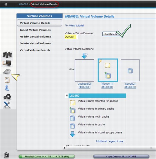
Figure 8-60 Virtual Volume Details- graphical summary
This graphical summary brings details of the present status of the virtual volume within the grid, plus the current operations taking place throughout the grid concerning that volume. The graphical summary helps you understand the dynamics of a logical mount, whether the volume is in cache at the mounting cluster, or whether it is being recalled from tape in a remote location.
|
Note: The physical resources are shown in the virtual volume summary, virtual volume details table, or the cluster-specific virtual volume properties table for the TS7720T and TS7740 cluster models.
|
The Virtual Volume Details window shows all clusters where the selected virtual volume is located within the grid. The icon representing each individual cluster is divided in three different areas by broken lines:
•The top area relates to the logical volume status.
•The intermediate area shows actions that are currently in course or pending for the cluster.
•The bottom area reports the status of the physical components that are related to that cluster.
The cluster that owns the logical volume being displayed is identified by the blue border around it. For instance, referring to Figure 8-60 on page 351, volume Z22208 is owned by cluster 1, where volume and a Flash Copy are in cache. Volume Z22208 is neither mounted nor available in the primary cache at cluster 2. At the same time, Z22208 is in the deferred incoming copy queue for cluster 0.
Figure 8-61 shows how the icons are distributed through the window, and where the pending actions are represented. The blue arrow icon over the cluster represents data being transferred from another cluster. The icon in the center of the cluster indicates data being transferred within the cluster.
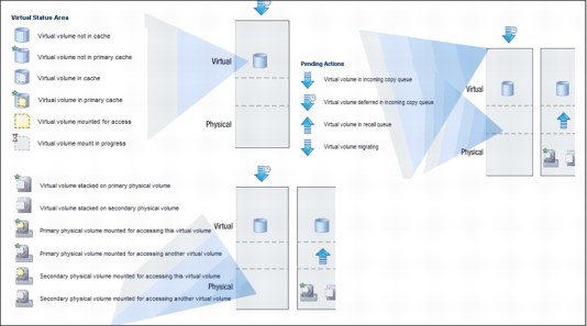
Figure 8-61 Details of the graphical summary area
Figure 8-62 shows a list of legends that can appear in the virtual volume details display, along with a brief description of the meaning of the icons.

Figure 8-62 Legend list for the graphical representation of the virtual volume details
Figure 8-63 shows the text section, which follows the graphical representation for the logical volume details window of the TS7700 Virtualization Engine MI, complementing the information about the logical volume. Details, such as the media type, compressed data size, current owner, whether the volume is currently mounted and where, and so on, are presented. It displays other properties for this volume, such as copy retention, copy policy, whether an automatic removal was attempted or not, and when if so.

Figure 8-63 Virtual volume details -text section
Virtual volume details: text
The virtual volume details and status are displayed in the Virtual volume details table:
Volser The VOLSER of the virtual volume. This value is a six-character number that uniquely represents the virtual volume in the virtual library.
Media Type The media type of the virtual volume. The possible values are Cartridge System Tape (400 MiB) or Enhanced Capacity Cartridge System Tape (800 MiB).
Current Volume Size (device)
Actual size (MiB) of the virtual volume.
Maximum Volume Capacity (device)
The maximum size (MiB) of the virtual volume. This capacity is set upon insert by the Data Class of the volume. Changes to one logical volume size are applied only when a load point write (scratch mount) occurs for that volume.
At volume close time, the value defined by data class or override is bounded to the volume and cannot be changed until the volume is reused. Any further changes to a data class override are not inherited by a volume until it is written again during a scratch mount and closed.
Current Owner The name of the cluster that currently owns the current version of the virtual volume.
Currently Mounted Indicates whether the virtual volume is mounted in a virtual drive.
Vnode The name of the vnode on which the virtual volume is mounted.
Virtual Drive The ID of the virtual drive on which the virtual volume is mounted.
Cache Copy Used for Mount
The cluster name of the cache that was chosen for I/O operations for mount based on Consistency policy, volume validity, residency, performance, and cluster mode.
The cluster name of the cache that was chosen for I/O operations for mount based on Consistency policy, volume validity, residency, performance, and cluster mode.
Cache Management Preference Group
The preference level for the Storage Group; it determines how soon volumes are removed from cache after their copy to tape. This information is only displayed if a physical library exists in the grid. The following values are possible:
The preference level for the Storage Group; it determines how soon volumes are removed from cache after their copy to tape. This information is only displayed if a physical library exists in the grid. The following values are possible:
0 Volumes in this group have preference to be removed from cache over other volumes.
1 Volumes in this group have preference to be retained in cache over other volumes. A least recently used (LRU) algorithm is used to select volumes for removal from cache if there are no volumes to remove in preference group 0.
Unknown The preference group cannot be determined.
Mount State The current mount state of the virtual volume. The following values are possible:
Mounted The volume is mounted.
Mount Pending A mount request has been received and is in progress.
Recall Queued/Requested
A mount request has been received and a recall request has been queued.
A mount request has been received and a recall request has been queued.
Recalling A mount request has been received and the virtual volume is being staged into the TVC from physical tape.
Last Accessed by a Host
The date and time that the virtual volume was last accessed by a host. The time recorded reflects the time zone in which the user’s browser
is located.
The date and time that the virtual volume was last accessed by a host. The time recorded reflects the time zone in which the user’s browser
is located.
Last Modified The date and time the virtual volume was last modified by a host. The time recorded reflects the time zone in which the user’s browser
is located.
is located.
Category The number of the category to which the virtual volume belongs.
Storage Group The name of the Storage Group that defines the primary pool for the premigration of the virtual volume. Only displayed for virtual volumes belonging to a private category (non-scratch).
Management Class The name of the Management Class applied to the volume. This policy defines the copy process for volume redundancy. Only displayed for virtual volumes belonging to a private category (non-scratch).
Storage Class The name of the Storage Class applied to the volume. This policy classifies virtual volumes to automate storage management. Only displayed for virtual volumes belonging to a private category (non-scratch).
Data Class The name of the Data Class applied to the volume. This policy classifies virtual volumes to automate storage management. Only displayed for virtual volumes belonging to a private category (non-scratch).
Volume Data State The state of the data on the virtual volume:
New The virtual volume is in the insert category or a private (non-Fast Ready) category and data has never been written to it.
Active The virtual volume is located within a private category and
contains data.
contains data.
Scratched The virtual volume is located within a scratch (Fast Ready) category and its data is not scheduled to be automatically deleted.
Pending Deletion The volume is located within a scratch (Fast Ready) category and its contents are a candidate for automatic deletion when the earliest deletion time has passed. Automatic deletion then occurs sometime later. The volume can be accessed for mount or category change before the automatic deletion and therefore the deletion can be incomplete.
Pending Deletion with Hold
The volume is located within a scratch (Fast Ready) category configured with hold and the earliest deletion time has not yet passed. The volume is not accessible by any host operation until the volume has left the hold state. After the earliest deletion time has passed, the volume then becomes a candidate for deletion and moves to the Pending Deletion state. While in this state, the volume is accessible by all legal host operations.
Deleted The volume is either currently within a scratch (Fast Ready) category or has previously been in a scratch (Fast Ready) category where it became a candidate for automatic deletion and was deleted. Any mount operation to this volume is treated as a scratch (Fast Ready) mount because no data is present.
Flash Copy Details of any existing flash copies. This field is only available in the TS7720 clusters. Possible values are:
Not active No Flash Copy is active. No Flash Copy was enabled at the host by a LI REQ operation.
Active A Flash Copy that affects this volume was enabled at the host by a LI REQ operation. Volume properties have not changed since Flash Copy time zero.
Created A Flash Copy that affects this volume was enabled at the host by a LI REQ operation. Volume properties between the live copy and the Flash Copy have changed. If the value Created is displayed under Flash Copy item, you can click it to start the Flash Copy details page. See the Flash Copy details page later in this chapter.
Earliest Deletion On This is the date and time when the virtual volume is deleted. Time recorded reflects the time zone in which the user’s browser is located. If there is no expiration date set, this value displays as a dash (-).
Logical WORM Whether the virtual volume is formatted as a Write Once, Read Many (WORM) volume. The possible values are Yes and No.
Cluster-specific Virtual Volume Properties
Figure 8-64 shows the Cluster-specific Virtual Volume Properties table shown in the last part of Virtual volume details page.
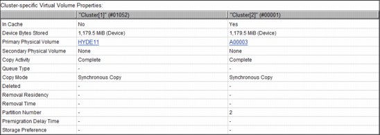
Figure 8-64 Cluster-specific virtual volume properties
The Cluster-specific Virtual Volume Properties table displays information about requesting virtual volumes on each cluster. These are properties that are specific to a cluster. Virtual volume details and the status displayed include the following properties:
Cluster The cluster location of the virtual volume copy. Each cluster location occurs as a separate column header.
In Cache Whether the virtual volume is in cache for this cluster.
Primary Physical Volume
The physical volume that contains the specified virtual volume. Click the VOLSER hyperlink to open the Physical Stacked Volume Details page for this physical volume. A value of None means that no primary physical copy is to be made. This column is only visible if a physical library is present in the grid. If there is at least one physical library in the grid, the value in this column is shown as a dash for those clusters not attached to a physical library.
The physical volume that contains the specified virtual volume. Click the VOLSER hyperlink to open the Physical Stacked Volume Details page for this physical volume. A value of None means that no primary physical copy is to be made. This column is only visible if a physical library is present in the grid. If there is at least one physical library in the grid, the value in this column is shown as a dash for those clusters not attached to a physical library.
Secondary Physical Volume
A secondary physical volume that contains the specified virtual volume. Click the VOLSER hyperlink to open the Physical Stacked Volume Details page for this physical volume. A value of None means that no secondary physical copy is to be made. This column is only visible if a physical library is present in the grid. If there is at least one physical library in the grid, the value in this column is shown as a dash for those clusters that are not attached to a physical library.
A secondary physical volume that contains the specified virtual volume. Click the VOLSER hyperlink to open the Physical Stacked Volume Details page for this physical volume. A value of None means that no secondary physical copy is to be made. This column is only visible if a physical library is present in the grid. If there is at least one physical library in the grid, the value in this column is shown as a dash for those clusters that are not attached to a physical library.
Copy Activity Status information about the copy activity of the virtual volume copy. The following values are possible:
Complete A consistent copy exists at this location.
In Progress A copy is required and currently in progress.
Required A copy is required at this location but has not started or completed.
Not Required A copy is not required at this location.
Reconcile Pending updates exist against this location’s volume. The copy activity updates after the pending updates get resolved.
Queue Type The type of queue as reported by the cluster. The following values are possible:
Rewind Unload (RUN)
The copy occurs before the rewind-unload operation completes at the host.
Deferred The copy occurs some time after the rewind-unload operation completes at the host.
Time Delayed The copy occurs after the defined time delays (create / access) in hours has expired.
Sync Deferred The copy was set to be synchronized, according to the synchronized mode copy settings, but the synchronized cluster was unable to be accessed. The copy is in the Deferred state. See “Synchronous mode copy” on page 77 for additional information about Synchronous mode copy settings and considerations.
Immediate Deferred A RUN copy that has been moved to the Deferred state due to copy timeouts or TS7700 grid states.
Copy Mode The copy behavior of the virtual volume copy. The following values are possible:
Rewind Unload (RUN)
The copy occurs before the rewind-unload operation completes at the host.
Deferred The copy occurs some time after the rewind-unload operation at the host.
Time Delayed A copy is only made if the specified time has elapsed.
No Copy No copy is made.
Sync The copy occurs upon any synchronization operation. See “Synchronous mode copy” on page 77 for additional information about settings and considerations.
Exist A consistent copy exists at this location although No Copy is intended. A consistent copy existed at this location at the time that the virtual volume was mounted. After the volume is modified, the Copy Mode of this location changes to No Copy.
Deleted The date and time when the virtual volume on the cluster was deleted. The time recorded reflects the time zone in which the user’s browser is located. If the volume has not been deleted, this value displays as a dash.
Removal Residency The residency state of the virtual volume. This field is displayed only if the grid contains a disk-only cluster. The following values are possible:
“-” Removal Residency does not apply to the cluster. This value is displayed if the cluster attaches to a physical tape library.
Removed The virtual volume has been removed from the cluster.
No Removal Attempted
The virtual volume is a candidate for removal, but the removal has not yet occurred.
The virtual volume is a candidate for removal, but the removal has not yet occurred.
Retained An attempt to remove the virtual volume occurred, but the operation failed. The copy on this cluster cannot be removed based on the configured copy policy and the total number of configured clusters. Removal of this copy lowers the total number of consistent copies within the grid to a value below the required threshold.
If a removal is expected at this location, verify that the copy policy is configured appropriately and that copies are being replicated to other peer clusters. This copy can be removed only after enough replicas exist on other peer clusters.
Deferred An attempt to remove the virtual volume occurred, but the operation failed. This state can result from a cluster outage or any state within the grid that disables or prevents replication. The copy on this cluster cannot be removed based on the configured copy policy and the total number of available clusters capable of replication.
Removal of this copy lowers the total number of consistent copies within the grid to a value below the required threshold. This copy can be removed only after enough replicas exist on other available peer clusters. A subsequent attempt to remove this volume occurs after no outage exists and replication is allowed to continue.
Pinned The virtual volume is pinned by the virtual volume storage class. The copy on this cluster cannot be removed until it is unpinned. When this value is present, the Removal Time value is Never.
Held The virtual volume is held in cache on the cluster at least until the Removal Time has passed. After the removal time has passed, the virtual volume copy is a candidate for removal. The Removal Residency value becomes No Removal Attempted if the volume is not accessed before the Removal Time passes.
The copy on this cluster is moved to the Resident state if it is not accessed before the Removal Time passes. If the copy on this cluster is accessed after the Removal Time has passed, it is moved back to the Held state.
Removal Time This field is displayed only if the grid contains a disk-only cluster. Values displayed in this field depend on values displayed in the Removal Residency fields shown in Table 8-9.
Table 8-9 Removal Time and Removal Residency value
|
Removal Residency state
|
Removal Time indicator
|
|||
|
Removed
|
The date and time the virtual volume was removed from the cluster.
|
|||
|
Held
|
The date and time the virtual volume becomes a candidate for removal.
|
|||
|
Pinned
|
The virtual volume is never removed from the cluster.
|
|||
|
No Removal Attempted, “-”, Retained, or Deferred
|
“-”
The Removal Time field is not applicable.
|
|||
The time recorded reflects the time zone in which the user’s browser is located.
|
Note: If the cluster contains a physical library, Removal Residency does not apply and this field displays a dash.
|
Partition number The partition number for a TS7720T tape attach cluster. Possible values are C0 - C7.
Premigration delay time
The basis for calculating the time period defined in Time-Delayed Premigration Delay. The following values are possible:
Volume Creation Calculate premigration delay starting with the time when the virtual volume was created.
Volume Last Accessed Calculate premigration delay starting with the time when the virtual volume was most recently accessed.
Volume Copy Retention Group
The name of the group that defines the preferred Auto Removal policy applicable to the virtual volume. The Volume Copy Retention Group provides more options to remove data from a TS7720 cluster or for a partition 0 (CP0) on a TS7720T tape attach cluster as the active data reaches full capacity.
Volumes become candidates for removal if an appropriate number of copies exist on peer clusters and the volume copy retention time has elapsed since the volume was last accessed. Volumes in each group are removed in order based on their least recently used access times. The volume copy retention time describes the number of hours a volume remains in cache before becoming a candidate for removal.
This field is displayed only if the cluster is a TS7720 (disk-only) part of a hybrid grid (one that combines TS7740 and TS7720 clusters), or for a partition 0 (CP0) on a TS7720T (tape attach) cluster. If the virtual volume is in a scratch (Fast Ready) category and is on a disk-only cluster, removal settings no longer apply to the volume, and the volume is a candidate for removal.
In this instance, the value displayed for the Volume Copy Retention Group is accompanied by a warning icon. The following values are possible:
Prefer Remove Removal candidates in this group are removed before removal candidates in the Prefer Keep group.
Prefer Keep Removal candidates in this group are removed after removal candidates in the Prefer Remove group.
Pinned Copies of volumes in this group are never removed from the accessing cluster. The volume copy retention time does not apply to volumes in this group. Volumes in this group that are subsequently moved to scratch become priority candidates for removal.
“-” Volume Copy Retention does not apply to a TS7740 cluster. This value (a dash indicating an empty value) is displayed if the cluster attaches to a physical tape library.
Flash Copy details
This section provides detailed information about the state of a virtual volume Flash Copy in the IBM TS7700 Virtualization Engine grid.
This page is only available for volumes with a created Flash Copy of a virtual volume. In this context, created Flash Copy means an existing Flash Copy, which becomes different from the live virtual volume. The live volume has been modified after Flash Copy time zero. For the volumes with a Flash Copy active (meaning no difference between the Flash Copy and live volume) as in Figure 8-63 on page 354, only the Virtual Volume details window is available (Flash Copy and live volume are identical).
Figure 8-65 shows a Flash Copy details pane in the Management Interface.

Figure 8-65 Flash Copy details window
The virtual volume details and status are displayed in the Virtual volume details table:
Volser The VOLSER of the virtual volume, which is a six-character value that uniquely represents the virtual volume in the virtual library.
Media type The media type of the virtual volume. Possible values are:
Cartridge System Tape
Enhanced Capacity Cartridge System Tape
Maximum Volume Capacity
The maximum size in MiB of the virtual volume. This capacity is set upon insert, and is based on the media type of a virtual volume.
Current Volume Size
Size of the data in MiB for this virtual volume.
Current Owner The name of the cluster that currently owns the latest version of the virtual volume.
Currently Mounted Whether the virtual volume is mounted in a virtual drive. If this value is Yes, these qualifiers are also displayed:
Vnode
The name of the vnode that the virtual volume is mounted on.
virtual drive
The ID of the virtual drive the virtual volume is mounted on.
Cache Copy Used for Mount
The name of the cluster that owns the cache chosen for I/O operations for mount. This selection is based on consistency policy, volume validity, residency, performance, and cluster mode.
Mount State The mount state of the logical volume. The following values are possible:
Mounted
The volume is mounted.
Mount Pending
A mount request has been received and is in progress.
Last Accessed by a Host
The date and time the virtual volume was last accessed by a host. The time recorded reflects the time zone in which the user’s browser is located.
Last Modified The date and time the virtual volume was last accessed by a host. The time recorded reflects the time zone in which the user’s browser is located.
Category The category to which the volume Flash Copy belongs.
Storage Group The name of the Storage Group that defines the primary pool for the pre-migration of the virtual volume.
Management Class The name of the Management Class applied to the volume. This policy defines the copy process for volume redundancy.
Storage Class The name of the Storage Class applied to the volume. This policy classifies virtual volumes to automate storage management.
Data Class The name of the Data Class applied to the volume.
Volume Data State The state of the data on the Flash Copy volume. The following values are possible:
Active
The virtual volume is located within a private category and contains data.
Scratched
The virtual volume is located within a scratch category and its data is not scheduled to be automatically deleted.
Pending Deletion
The volume is located within a scratch category and its contents are a candidate for automatic deletion when the earliest deletion time has passed. Automatic deletion then occurs sometime thereafter. This volume can be accessed for mount or category change before the automatic deletion, in which case the deletion can be postponed
or canceled.
or canceled.
Pending Deletion with Hold
The volume is located within a scratch category that is configured with hold and the earliest deletion time has not yet passed. The volume is not accessible by any host operation until the volume has left the hold state. After the earliest deletion time passes, the volume becomes a candidate for deletion and moved to the Pending Deletion state. While in this state, the volume is accessible by all legal host operations.
Earliest Deletion On
Not applicable to flash copies (-).
Logical WORM Not applicable to flash copies (-).
Cluster-specific Flash Copy volume properties
This is the second part of the Flash Copy details window. Figure 8-66 shows the cluster-specific Flash Copy volume properties in the Management Interface. Notice that cluster location shows as a separated column header. Only clusters that are part of a disaster recovery family are shown.
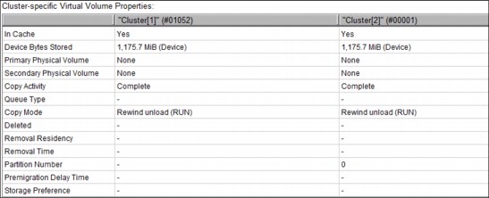
Figure 8-66 Cluster-specific Flash Copy Properties
The Cluster-specific Flash Copy Properties window displays cluster-related information for the Flash Copy volume being displayed:
Cluster The cluster location of the Flash Copy, on the header of the column. Only clusters that are part of a disaster recovery family are shown.
In Cache Whether the virtual volume is in cache for this cluster.
Device Bytes Stored
The number of actual bytes (MiB) used by each cluster to store the volume. This amount can vary between clusters based on settings and configuration.
Copy Activity Status information about the copy activity of the virtual volume copy.
Complete
This cluster location completed a consistent copy of the volume.
In Progress
A copy is required and currently in progress.
Required
A copy is required at this location but has not started or completed.
Not Required
A copy is not required at this location
Reconcile
Pending updates exist against this location’s volume. The copy activity updates after the pending updates get resolved.
Time Delayed Until [time]
A copy is delayed as a result of Time Delayed Copy mode. The value for [time] is the next earliest date and time that the volume is eligible for copies.
Queue Type The type of queue as reported by the cluster. Possible values are:
Rewind Unload (RUN)
The copy occurs before the rewind-unload operation completes at the host.
Deferred
The copy occurs some time after the rewind-unload operation completes at the host.
Sync Deferred
The copy was set to be synchronized, according to the synchronized mode copy settings, but the synchronized cluster could not be accessed. The copy is in the deferred state.
Immediate Deferred
A RUN copy that has been moved to the deferred state due to copy timeouts or TS7700 Grid states.
Time Delayed
The copy occurs sometime after the delay period has been exceeded.
Copy Mode The copy behavior of the virtual volume copy. Possible values are:
Rewind Unload (RUN)
The copy occurs before the rewind-unload operation completes at the host.
Deferred
The copy occurs some time after the rewind-unload operation completes at the host.
No Copy
No copy is made.
Sync
The copy occurs upon any synchronization operation.
Time Delayed
The copy occurs sometime after the delay period has been exceeded.
Exists
A consistent copy exists at this location although No Copy is intended. This happens when a consistent copy existed at this location at the time the virtual volume was mounted. After the volume is modified, the copy mode of this location changes to No Copy.
Deleted The date and time when the virtual volume on the cluster was deleted. The time recorded reflects the time zone in which the user’s browser is located. If the volume has not been deleted, this value displays a dash.
Removal Residency
Not applicable to flash copies.
Removal Time
Not applicable to flash copies.
Volume Copy Retention Group
Not applicable to flash copies.
Insert Virtual Volumes
Use this page to insert a range of virtual volumes in the TS7700 Virtualization Engine. Virtual volumes inserted in an individual cluster are available to all clusters within a grid configuration.
The Insert Virtual Volumes window is shown in Figure 8-67.

Figure 8-67 Insert Virtual Volumes window
The Insert Virtual Volume window shows the Currently availability across entire grid table. This table shows the total of the already inserted volumes, the maximum number of volumes allowed in the grid, and the available slots (the difference between the maximum allowed and the currently inserted numbers). Clicking Show/Hide under the table shows or hides the information box with the already inserted volume ranges, quantities, media type, and capacity. Figure 8-68 shows the inserted ranges box.

Figure 8-68 Show logical volume ranges
Insert a new virtual volume range
Use the following fields to insert a range of new virtual volumes:
Starting VOLSER The first virtual volume to be inserted. The range for inserting virtual volumes begins with this VOLSER number.
Quantity Select this option to insert a set number of virtual volumes beginning with the Starting VOLSER. Enter the quantity of virtual volumes to be inserted in the adjacent field. You can insert up to 10,000 virtual volumes at one time.
Ending VOLSER Select this option to insert a range of virtual volumes. Enter the ending VOLSER number in the adjacent field.
Initially owned by The name of the cluster that will own the new virtual volumes. Select a cluster from the menu.
Media type Media type of the virtual volumes. The following values are possible: Cartridge System Tape (400 MiB) or Enhanced Capacity Cartridge System Tape (800 MiB).
See 1.5, “Data storage values” on page 12 for additional information about the use of binary prefixes.
Set Constructs Select this check box to specify constructs for the new virtual volumes. Then, use the menu under each construct to select a predefined construct name.
You can set constructs only for virtual volumes that are used by hosts that are not multiple virtual systems (MVS) hosts. MVS hosts automatically assign constructs for virtual volumes and overwrite any manually assigned constructs.
You can specify the use of any or all of the following constructs: Storage Group, Management Class, Storage Class, or Data Class.
Modify Virtual Volumes window
Use the Modify Virtual Volumes window shown in Figure 8-69 on page 368 to modify the constructs associated with existing virtual volumes in the TS7700 Virtualization Engine composite library.
|
Note: The Modify Virtual Volume function is helpful to manage virtual volumes that belong to a non-MVS host that is not aware of constructs. MVS hosts automatically assign constructs for virtual volumes.
Management Interface acts indistinctly over any logical volume belonging to the cluster or grid regardless of the host that owns the volume, under user command.
Notice that new constructs will only take effect over the modified volume or range after a mount-demount sequence, or by using the LI REQ COPYRFSH command.
|

Figure 8-69 Modify Virtual Volumes page
To display a range of existing virtual volumes, enter the starting and ending VOLSERs in the fields at the top of the page and click Show.
To modify constructs for a range of logical volumes, identify a Volume Range, and then, click the Constructs menu to select construct values and click Modify. The menus have these options:
•Volume Range: The range of logical volumes to be modified.
– From: The first VOLSER in the range.
– To: The last VOLSER in the range.
•Constructs: Use the following menus to change one or more constructs for the identified Volume Range. From each menu, you can select a predefined construct to apply to the Volume Range, No Change to retain the current construct value, or dashes (--------) to restore the default construct value:
– Storage Groups: Changes the Storage Group for the identified Volume Range.
– Storage Classes: Changes the Storage Class for the identified Volume Range.
– Data Classes: Changes the Data Class for the identified Volume Range.
– Management Classes: Changes the Management Class for the identified Volume Range.
You are asked to confirm your decision to modify logical volume constructs. To continue with the operation, click OK. To abandon the operation without modifying any logical volume constructs, click Cancel.
Delete Virtual Volumes window
Use the Delete Virtual Volumes window shown in Figure 8-70 on page 369 to delete unused virtual volumes from the TS7700 Virtualization Engine that are in the Insert Category (FF00).
|
Note: Only the unused logical volumes can be deleted through this window, meaning volumes in insert category FF00 that have never been mounted or have had its category, constructs, or attributes modified by a host. Otherwise, those logical volumes must be deleted from host.
|
The normal way to delete several virtual scratch volumes is by initiating the activities from the host. With Data Facility Storage Management Subsystem (DFSMS)/Removable Media Management (RMM) as the Tape Management System, it is done using RMM commands.

Figure 8-70 Delete Virtual Volumes window
To delete unused virtual volumes, select one of the options described next, and click Delete Volumes. A confirmation window is displayed. Click OK to delete or Cancel to cancel. To view the current list of unused virtual volume ranges in the TS7700 Virtualization Engine Grid, enter a virtual volume range at the bottom of the window and click Show. A virtual volume range deletion can be canceled while in progress at the Cluster Operation History window.
This window has the following options:
•Delete ALL unused virtual volumes: Deletes all unused virtual volumes across all VOLSER ranges.
•Delete specific range of unused virtual volumes: All unused virtual volumes in the entered VOLSER range are deleted. Enter the VOLSER range:
– From: The start of the VOLSER range to be deleted if Delete specific range of unused virtual volumes is selected.
– To: The end of the VOLSER range to be deleted if Delete specific range of unused virtual volumes is selected.
Move Virtual Volumes window
Use the window shown in Figure 8-71 on page 370 to move a range of virtual volumes that are used by the TS7740 Virtualization Engine or TS7720T from one physical volume or physical volume range to a new target pool. Also, you can cancel a move request already in progress.
If a move operation is already in progress, a warning message is displayed. You can view move operations already in progress from the Events window.
Figure 8-71 shows the Move Virtual Volumes window.
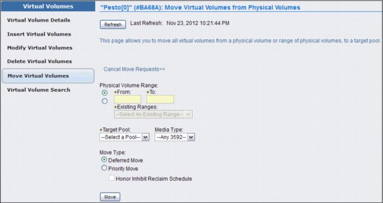
Figure 8-71 MI Move Virtual Volumes
To cancel a move request, select the Cancel Move Requests link. The following options to cancel a move request are available:
•Cancel All Moves: Cancels all move requests.
•Cancel Priority Moves Only: Cancels only priority move requests.
•Cancel Deferred Moves Only: Cancels only Deferred move requests.
•Select a Pool: Cancels move requests from the designated source pool (1 - 32), or from all source pools.
If you want to move virtual volumes, you must define a volume range or select an existing range, select a target pool, and identify a move type:
•Physical Volume Range: The range of physical volumes from where the virtual volumes must be removed. You can use either this option or Existing Ranges to define the range of volumes to move, but not both.
– From: VOLSER of the first physical volume in the range.
– To: VOLSER of the last physical volume in the range.
•Existing Ranges: The list of existing physical volume ranges. You can use either this option or Volume Range to define the range of volumes to move, but not both.
•Media Type: The media type of the physical volumes in the range to move. If no available physical stacked volume of the media type is in the range specified, no virtual volume
is moved.
is moved.
•Target Pool: The number (1 - 32) of the target pool to which virtual volumes are moved.
•Move Type: Used to determine when the move operation occurs. The following values are possible:
– Deferred: Move operation will occur in the future as schedules enable.
– Priority: Move operation occurs as soon as possible.
– Honor Inhibit Reclaim schedule: An option of the Priority Move Type, it specifies that the move schedule occurs with the Inhibit Reclaim schedule. If this option is selected, the move operation does not occur when Reclaim is inhibited.
After you define your move operation parameters and click Move, you will be asked to confirm your request to move the virtual volumes from the defined physical volumes. If you select Cancel, you return to the Move Virtual Volumes window.
Virtual Volumes Search window
Use the window shown in Figure 8-72 to search for virtual volumes in a specific TS7700 Virtualization Engine Cluster by VOLSER, category, media type, expiration date, or inclusion in a group or class. With the new TS7720T introduced in R3.2 of Licensed Internal Code, a new search option is available to search by Partition Number.

Figure 8-72 MI Virtual Volume Search entry window
You can view the results of a previous query, or create a new query to search for virtual volumes.
|
Tip: Only one search can be run at a time. If a search is in progress, an information message occurs at the top of the Virtual Volumes Search window. You can cancel a search in progress by clicking Cancel Search.
|
To view the results of a previous search query, select the Previous Searches hyperlink to see a table containing a list of previous queries. Click a query name to display a list of virtual volumes that match the search criteria.
Up to 10 previously named search queries can be saved. To clear the list of saved queries, select the check box next to one or more queries to be removed, select Clear from the menu, and click Go. This operation does not clear a search query already in progress.
You are asked to confirm your decision to clear the query list. Select OK to clear the list of saved queries, or Cancel to retain the list of queries.
To create a new search query, enter a name for the new query. Enter a value for any of the fields and select Search to initiate a new virtual volume search. The query name, criteria, start time, and end time are saved along with the search results.
To search for a specific VOLSER, enter your parameters in the New Search Name and Volser fields and then click Search.
Figure 8-73 shows an example of the Virtual Volume Search Results window. The result can be printed or downloaded to a spreadsheet for post-processing.

Figure 8-73 Virtual Volume Search Results page
If you are looking for the results of earlier searches, click Previous Searches on the Virtual Volume Search window, shown in Figure 8-72 on page 371.
The following entry fields are shown in Figure 8-72 on page 371, where you can enter your Virtual Volume search, are defined:
•Volser: The volume’s serial number. This field can be left blank. You can also use the following wildcard characters in this field:
– Percent sign (%): Represents zero or more characters.
– Asterisk (*): Translated to % (percent). Represents zero or more characters.
– Period (.): Translated to _ (single underscore). Represents one character.
– A single underscore (_): Represents one character.
– Question mark (?): Translated to _ (single underscore). Represents one character.
•Category: The name of the category to which the virtual volume belongs. This value is a four-character hexadecimal string. For instance, 0002/0102 (scratch MEDIA2), 000E (error), 000F/001F (private), FF00 (insert) are possible values for Scratch and Specific categories. Wild card characters can be used in this field. This field can be left blank.
•Media Type: The type of media on which the volume exists. Use the menu to select from the available media types. This field can be left blank.
•Expire Time: The amount of time in which virtual volume data will expire. Enter a number. This field is qualified by the values Equal to, Less than, or Greater than in the preceding menu and defined by the succeeding menu under the heading Time Units. This field can be left blank.
•Removal Residency: The automatic removal residency state of the virtual volume. This field is not displayed for TS7740 clusters. In a TS7720T (tape attach) configuration, this field is displayed only when the volume is in partition 0 (CP0). The following values are possible:
– Blank (ignore): If this field is empty (blank), the search ignores any values in the Removal Residency field. This is the default selection.
– Removed: The search includes only virtual volumes that have been removed.
– Removed Before: The search includes only virtual volumes removed before a specific date and time. If you select this value, you must also complete the fields for Removal Time.
– Removed After: The search includes only virtual volumes removed after a certain date and time. If you select this value, you must also complete the fields for Removal Time.
– In Cache: The search includes only virtual volumes in the cache.
– Retained: The search includes only virtual volumes classified as retained.
– Deferred: The search includes only virtual volumes classified as deferred.
– Held: The search includes only virtual volumes classified as held.
– Pinned: The search includes only virtual volumes classified as pinned.
– No Removal Attempted: The search includes only virtual volumes that have not previously been subject to a removal attempt.
– Removable Before: The search includes only virtual volumes that are candidates for removal before a specific date and time. If you select this value, you must also complete the fields for Removal Time.
– Removable After: The search includes only virtual volumes that are candidates for removal after a specific date and time. If you select this value, you must also complete the fields for Removal Time.
•Removal Time: This field is displayed only if the grid contains a TS7720 or a TS7720T. Values displayed in this field are dependent on the values shown in the Removal Residency field. These values reflect the time zone in which your browser is located:
– Date: The calendar date according to month (M), day (D), and year (Y); it takes the format: MM/DD/YYYY. This field includes a date chooser calendar icon. You can enter the month, day, and year manually, or you can use the calendar chooser to select a specific date. The default for this field is blank.
– Time: The Coordinated Universal Time (Coordinated Universal Time) in hours (H), minutes (M), and seconds (S). The values in this field must take the form HH:MM:SS. Possible values for this field include 00:00:00 through 23:59:59. This field includes a time chooser clock icon. You can enter hours and minutes manually using 24-hour time designations, or you can use the time chooser to select a start time based on a 12-hour (AM/PM) clock. The default for this field is midnight (00:00:00).
•Volume Copy Retention Group: The name of the Volume Copy Retention Group for
the cluster.
the cluster.
The Volume Copy Retention Group provides more options to remove data from a disk-only TS7700 Virtualization Engine as the active data reaches full capacity. Volumes become candidates for removal if an appropriate number of copies exist on peer clusters and the volume copy retention time has elapsed since the volume was last accessed.
Volumes in each group are removed in order based on their least recently used access times. The volume copy retention time describes the number of hours a volume remains in cache before becoming a candidate for removal.
This field is only visible if the selected cluster is a TS7720 or TS7720T (for volumes in CP0). The following values are valid:
– Blank (ignore): If this field is empty (blank), the search ignores any values in the Volume Copy Retention Group field. This is the default selection.
– Prefer Remove: Removal candidates in this group are removed before removal candidates in the Prefer Keep group.
– Prefer Keep: Removal candidates in this group are removed after removal candidates in the Prefer Remove group.
– Pinned: Copies of volumes in this group are never removed from the accessing cluster. The volume copy retention time does not apply to volumes in this group. Subsequently, volumes in this group that are moved to scratch become priority candidates for removal.
|
Tip: Plan when assigning volumes to this group to avoid cache overruns.
|
– “-”: Volume Copy Retention does not apply to the TS7740 cluster and TS7720T (for volume in CP1to CP7). This value (a dash indicating an empty value) is displayed if the cluster attaches to a physical tape library.
•Storage Group: The name of the Storage Group in which the virtual volume resides. You can enter a name in the empty field, or select a name from the adjacent menu. This field can be left blank.
•Management Class: The name of the Management Class to which the virtual volume belongs. You can enter a name in the empty field, or select a name from the adjacent menu. This field can be left blank.
•Storage Class: The name of the Storage Class to which the virtual volume belongs. You can enter a name in the empty field, or select a name from the adjacent menu. This field can be left blank.
•Data Class: The name of the Data Class to which the virtual volume belongs. You can enter a name in the empty field, or select a name from the adjacent menu. This field can be left blank.
•Mounted: Whether the virtual volume is mounted. The following values are possible:
– Ignore: Ignores any values in the Mounted field. This is the default selection.
– Yes: Includes only mounted virtual volumes.
– No: Includes only unmounted virtual volumes.
•Logical WORM: Whether the logical volume is defined as Write Once Read Many (WORM). The following values are possible:
– Ignore: Ignores any values in the Logical WORM field. This is the default selection.
– Yes: Includes only WORM logical volumes.
– No: Does not include any WORM logical volumes.
|
Remember: You can print or download the results of a search query using Print Report or Download Spreadsheet on the Volumes found table at the end of the Search Results window, as shown in Figure 8-73 on page 372.
|
Categories
Use this page to add, modify, or delete a scratch (Fast Ready) category of virtual volumes. You can also use this page to view the total number of volumes defined by custom, inserted, and damaged categories. A category is a grouping of virtual volumes for a predefined use. A scratch (Fast Ready) category groups virtual volumes for non-specific use. This grouping enables faster mount times because the IBM TS7700 Virtualization Engine can order category mounts without recalling data from a stacked volume.
Figure 8-74 shows the Category window in the TS7700 MI.

Figure 8-74 Categories window
You can display the already defined categories, as shown in the Figure 8-75.

Figure 8-75 Displaying existing categories
Table 8-10 describes values displayed on the Categories table as shown in Figure 8-75 on page 375.
Table 8-10 Category values
|
Column name
|
Description
|
||
|
Categories
|
The type of category that defines the virtual volume. The following values are valid:
•Scratch: Categories within the user-defined private range 0x0001 through 0xEFFF that are defined as scratch (Fast Ready). Click the plus sign (+) icon to expand this heading and reveal the list of categories defined by this type. Expire time and hold values are shown in parentheses next to the category number. See Table 8-10 for descriptions of these values.
•Private: Custom categories established by a user, within the range of 0x0001 - 0xEFFF. Click the plus sign (+) icon to expand this heading and reveal the list of categories defined by this type.
•Damaged: A system category identified by the number 0xFF20. Virtual volumes in this category are considered damaged.
•Insert: A system category identified by the number 0xFF00. Inserted virtual volumes are held in this category until moved by the host into a scratch category.
If no defined categories exist for a certain type, that type is not displayed on the Categories table.
|
||
|
Owning Cluster
|
Names of all clusters in the grid. Expand a category type or number to display. This column is visible only when the accessing cluster is part of a grid.
|
||
|
Counts
|
The total number of virtual volumes according to category type, category, or owning cluster.
|
||
|
Scratch Expired
|
The total number of scratch volumes per owning cluster that are expired. The total of all scratch expired volumes is the number of ready scratch volumes.
|
||
You can use the Categories table to add, modify, or delete a scratch category, or to change the way information is displayed.
|
Tip: The total number of volumes within a grid is not always equal to the sum of all category counts. Volumes can change category multiple times per second, which makes the snapshot count obsolete.
|
Table 8-11 describes the actions that can be performed on the Categories page.
Table 8-11 Available actions on the Categories page
|
Action
|
Steps to perform action
|
|
|
Add a scratch category
|
1. Select Add Scratch Category.
2. Define the following category properties:
– Category: A four-digit hexadecimal number that identifies the category. The valid characters for this field are A - F and 0 - 9. Do not use category name 0000 or “FFxx”, where xx equals 0 - 9 or A - F. 0000 represents a null value, and “FFxx” is reserved for hardware.
– Expire: The amount of time after a virtual volume is returned to the scratch (Fast Ready) category before its data content is automatically delete-expired. Select an expiration time from the menu. If you select No Expiration, volume data never automatically delete-expires. If you select Custom, enter values for the following fields:
• Time: Enter a number in the field according to these restrictions:
1 - 32,767 if unit is hours
1 - 1365 if unit is days
1 - 195 if unit is weeks
• Time Unit: Select a corresponding unit from the menu.
– Set Expire Hold: Check this box to prevent the virtual volume from being mounted or having its category and attributes changed before the expire time has elapsed. Checking this field activates the hold state for any volumes currently in the scratch (Fast Ready) category and for which the expire time has not yet elapsed. Clearing this field removes the access restrictions on all volumes currently in the hold state within this scratch (Fast Ready) category.
|
|
|
Modify a scratch category
|
You can modify a scratch category in two ways:
•Select a category on the table, and then, select Actions → Modify Scratch Category.
•Right-click a category on the table and either hold, or select Modify Scratch Category from the menu.
You can modify the following category values:
•Expire
•Set Expire Hold
You can modify one category at a time.
|
|
|
Delete a scratch category
|
You can delete a scratch category in two ways:
1. Select a category on the table, and then, select Actions → Delete Scratch Category.
2. Right-click a category on the table and select Delete Scratch Category from the menu.
You can delete only one category at a time.
|
|
|
Hide or show columns on the table
|
1. Right-click the table header.
2. Click the check box next to a column heading to hide or show that column in the table. Column headings that are checked display on the table.
|
|
|
Filter the table data
|
Follow these steps to filter using a string of text:
1. Click in the Filter field.
2. Enter a search string.
3. Press Enter.
Follow these steps to filter by column heading:
1. Click the down arrow next to the Filter field.
2. Select the column heading to filter by.
3. Refine the selection:
– Categories: Enter a whole or partial category number and press Enter.
– Owning Cluster: Enter a cluster name or number and press Enter. Expand the category type or category to view highlighted results.
– Counts: Enter a number and press Enter to search on that number string.
– Scratch Expired: Enter a number and press Enter to search on that number string.
|
|
|
Reset the table to its default view
|
1. Right-click the table header.
2. Click Reset Table Preferences.
|
|
|
Note: There is no cross-check between defined categories in the z/OS systems and the definitions in the TS7700.
|
8.2.7 The Physical icon
The topics in this section present information related to monitoring and manipulating physical volumes in the TS7740 and TS7720T Virtualization Engine. Use the window shown in Figure 8-76 to view or modify settings for physical volume pools to manage the physical volumes used by the TS7740 Virtualization Engine.
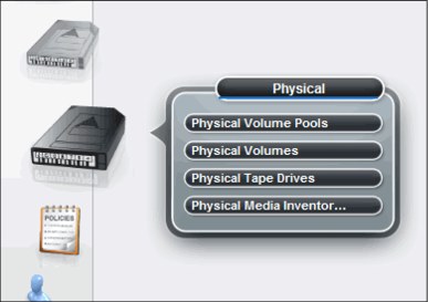
Figure 8-76 Physical icon
Physical Volume Pools
The Physical Volume Pools properties table displays the media properties and encryption settings for every physical volume pool defined for a specific TS7720T or TS7740 cluster in the grid. This table contains these tabs:
•Pool Properties
•Encryption Settings
|
Tip: Pools 1 - 32 are preinstalled and initially set to default attributes. Pool 1 functions as the default pool and is used if no other pool is selected.
|
Figure 8-77 show an example of the Physical Volume Pools page. There is a link available for a tutorial showing you how to modify pool encryption settings. Click the link to see the tutorial material. This page is visible but disabled on the TS7700 Virtualization Engine MI if the grid possesses a physical library, but the selected cluster does not. This message is displayed:
The cluster is not attached to a physical tape library.
The window shown in Figure 8-77 enables you to view or modify settings for physical volume pools.

Figure 8-77 Physical Volume Pools Properties table
The Physical Volume Pool Properties table displays the encryption setting and media properties for every physical volume pool that is defined in a TS7740 and TS7720T. This table contains two tabs: Pool Properties and Physical Tape Encryption Settings. The following information is displayed:
•Under Pool Properties:
– Pool: The pool number. This number is a whole number 1 - 32, inclusive.
– Media Class: The supported media class of the storage pool. The valid value is 3592.
– First Media (Primary): The primary media type that the pool can borrow from or return to the common scratch pool (Pool 0). The values displayed in this field are dependent upon the configuration of physical drives in the cluster. See Table 4-7 on page 121 for First and Second Media values based on drive configuration.
The primary media type can have the following values:
Any 3592 Any media with a 3592 format.
None The only option available if the Primary Media type is any 3592. This option is only valid when the Borrow Indicator field value is No Borrow, Return or No Borrow, Keep.
JA Enterprise Tape Cartridge (ETC).
JB Extended Data Enterprise Tape Cartridge (ETCL).
JC Enterprise Advanced Data Cartridge (EADC).
JJ Enterprise Economy Tape Cartridge (EETC).
JK Enterprise Advanced Economy Tape Cartridge (EAETC).
– Second Media (Secondary): The second choice of media type from which the pool can borrow. Options shown exclude the media type chosen for First Media. The following values are possible:
Any 3592 Any media with a 3592 format.
None The only option available if the Primary Media type is any 3592. This option is only valid when the Borrow Indicator field value is No Borrow, Return or No Borrow, Keep.
JA Enterprise Tape Cartridge (ETC).
JB Extended Data Enterprise Tape Cartridge (ETCL).
JC Enterprise Advanced Data Cartridge (EADC).
JJ Enterprise Economy Tape Cartridge (EETC).
JK Enterprise Advanced Economy Tape Cartridge (EAETC).
– Borrow Indicator: Defines how the pool is populated with scratch cartridges. The following values are possible:
Borrow, Return A cartridge is borrowed from the Common Scratch Pool (CSP) and returned to the CSP when emptied.
Borrow, Keep A cartridge is borrowed from the CSP and retained by the actual pool, even after being emptied.
No Borrow, Return A cartridge is not borrowed from CSP, but an emptied cartridge is placed in CSP. This setting is used for an empty pool.
No Borrow, Keep A cartridge is not borrowed from CSP, and an emptied cartridge is retained in the actual pool.
– Reclaim Pool: The pool to which virtual volumes are assigned when reclamation occurs for the stacked volume on the selected pool.
|
Important: The reclaim pool that is designated for the Copy Export pool needs to be set to the same value as the Copy Export pool. If the reclaim pool is modified, Copy Export disaster recovery capabilities can be compromised.
|
If there is a need to modify the reclaim pool that is designated for the Copy Export pool, the reclaim pool must not be set to the same value as the primary pool or the reclaim pool designated for the primary pool. If the reclaim pool for the Copy Export pool is the same as either of the other two pools mentioned, the primary and backup copies of a virtual volume might exist on the same physical media. If the reclaim pool for the Copy Export pool is modified, it is the user’s responsibility to Copy Export volumes from the reclaim pool.
– Maximum Devices: The maximum number of physical tape drives that the pool can use for premigration.
– Export Pool: The type of export supported if the pool is defined as an Export Pool (the pool from which physical volumes are exported). The following values are possible:
Not Defined The pool is not defined as an Export pool.
Copy Export The pool is defined as a Copy Export pool.
– Export Format: The media format used when writing volumes for export. This function can be used when the physical library recovering the volumes supports a different media format than the physical library exporting the volumes. This field is only enabled if the value in the Export Pool field is Copy Export. The following values are valid for this field:
Default The highest common format supported across all drives in the library. This is also the default value for the Export Format field.
E06 Format of a 3592-E06 Tape Drive.
E07 Format of a 3592-E07 Tape Drive.
– Days Before Secure Data Erase: The number of days a physical volume that is a candidate for Secure Data Erase can remain in the pool without access to a physical stacked volume. Each stacked physical volume possesses a timer for this purpose, which is reset when a virtual volume on the stacked physical volume is accessed. Secure Data Erase occurs later, based on an internal schedule. Secure Data Erase renders all data on a physical stacked volume inaccessible. The valid range of possible values is 1 - 365. Clearing the check box deactivates this function.
– Days Without Access: The number of days the pool can persist without access to set a physical stacked volume as a candidate for reclamation. Each physical stacked volume has a timer for this purpose, which is reset when a virtual volume is accessed. The reclamation occurs later, based on an internal schedule. The valid range of possible values is 1 - 365. Clearing the check box deactivates this function.
– Age of Last Data Written: The number of days the pool has persisted without write access to set a physical stacked volume as a candidate for reclamation. Each physical stacked volume has a timer for this purpose, which is reset when a virtual volume is accessed. The reclamation occurs later, based on an internal schedule. The valid range of possible values is 1 - 365. Clearing the check box deactivates this function.
– Days Without Data Inactivation: The number of sequential days that the data ratio of the pool has been higher than the Maximum Active Data used to set a physical stacked volume as a candidate for reclamation. Each physical stacked volume has a timer for this purpose, which is reset when data inactivation occurs. The reclamation occurs later, based on an internal schedule. The valid range of possible values is 1 - 365. Clearing the check box deactivates this function. If deactivated, this field is not used as a criteria for reclaim.
– Maximum Active Data: The ratio of the amount of active data in the entire physical stacked volume capacity. This field is used with Days Without Data Inactivation. The valid range of possible values is 5 - 95%. This function is disabled if Days Without Data Inactivation is not checked.
– Reclaim Threshold: The percentage used to determine when to perform reclamation of free storage on a stacked volume. When the amount of active data on a physical stacked volume drops below this percentage, a reclaim operation is performed on the stacked volume. The valid range of possible values is 0 - 95% and can be selected in 5% increments; 35% is the default value.
To modify pool properties, click the check box next to one or more pools shown on the Pool Properties tab, select Modify Pool Properties from the menu, and click Go.
•Physical Tape Encryption Settings
The Physical Tape Encryption Settings tab displays the encryption settings for physical volume pools. The following encryption information is displayed on this tab:
– Pool: The pool number. This number is a whole number 1 - 32, inclusive.
– Encryption: The encryption state of the pool. The following values are possible:
Enabled Encryption is enabled on the pool.
Disabled Encryption is not enabled on the pool. When this value is selected, key modes, key labels, and check boxes are disabled.
– Key Mode 1: Encryption mode used with Key Label 1. The following values are available:
Clear Label The data key is specified by the key label in clear text.
Hash Label The data key is referenced by a computed value corresponding to its associated public key.
None Key Label 1 is disabled.
“-” The default key is in use.
– Key Label 1: The current encryption key Label 1 for the pool. The label must consist of ASCII characters and cannot exceed 64 characters. Leading and trailing blanks are removed, but an internal space is allowed. Lowercase characters are internally converted to uppercase upon storage. Therefore, key labels are reported using uppercase characters.
|
Note: You can use identical values in Key Label 1 and Key Label 2, but you must define each label for each key.
|
If the encryption state is Disabled, this field is blank. If the default key is used, the value in this field is default key.
– Key Mode 2: Encryption mode used with Key Label 2. The following values are valid:
Clear Label The data key is specified by the key label in clear text.
Hash Label The data key is referenced by a computed value corresponding to its associated public key.
None Key Label 2 is disabled.
“-” The default key is in use.
– Key Label 2: The current encryption Key Label 2 for the pool. The label must consist of ASCII characters and cannot exceed 64 characters. Leading and trailing blanks are removed, but an internal space is allowed. Lowercase characters are internally converted to uppercase upon storage. Therefore, key labels are reported using uppercase characters.
If the encryption state is Disabled, this field is blank. If the default key is used, the value in this field is default key.
To modify encryption settings, complete these steps:
1. Select one or more pools shown on the Physical Tape Encryption Settings tab.
2. Select Modify Encryption Settings from the menu and click Go.
Physical Volumes
The topics in this section present information related to monitoring and manipulating physical volumes in the TS7720T and TS7740 Virtualization Engine. This page is visible but disabled on the TS7700 Virtualization Engine MI if the grid possesses a physical library, but the selected cluster does not.
The following message is displayed:
The cluster is not attached to a physical tape library.
|
Tip: This page is not visible on the TS7700 Virtualization Engine MI if the grid does not possess a physical library.
|
TS7700 Virtualization Engine MI pages collected under the Physical icon can help you view or change settings or actions related to the physical volumes and pools, physical drives, media inventory, TVC, and a physical library. Figure 8-78 shows the navigation and the Physical Volumes page.
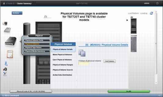
Figure 8-78 Physical Volumes navigation and options
The following options are available selections under Physical Volumes:
Physical Volume Details
Use this page to obtain detailed information about a physical stacked volume in the IBM TS7740 and TS7720T Virtualization Engine. Figure 8-79 shows a sample of the Physical Volume Details window.
You can download the list of virtual volumes in the physical stacked volume being displayed by clicking Download List of Virtual Volumes under the table.

Figure 8-79 Physical Volume Details page
The following information is displayed when details for a physical stacked volume are retrieved:
VOLSER Six-character VOLSER number of the physical stacked volume.
Type The media type of the physical stacked volume. The following values are possible:
JA (ETC) Enterprise Tape Cartridge
JB (ETCL) Enterprise Extended-Length Tape Cartridge
JC (EATC) Enterprise Advanced Tape Cartridge
JJ (EETC) Enterprise Economy Tape Cartridge
JK (EAETC) Enterprise Advanced Economy Tape Cartridge
|
Note: JC (EATC) and JK (EAETC) media types are only available if the highest common format (HCF) is set to E07 or higher.
|
Recording Format The format used to write the media. The following values are possible:
Undefined The recording format used by the volume is not recognized as a supported format.
J1A
E05
E05E E05 with Encryption
E06
E06E E06 with Encryption
E07
E07E E07 with Encryption
Volume State The following values are possible:
Read-Only The volume is in a read-only state.
Read/write The volume is in a read/write state.
Unavailable The volume is in use by another task or is in a pending eject state.
Destroyed The volume is damaged and unusable for mounting.
Copy Export Pending
The volume is in a pool that is being exported as part of an in-progress Copy Export.
The volume is in a pool that is being exported as part of an in-progress Copy Export.
Copy Exported The volume has been ejected from the library and removed to offsite storage.
Copy Export Reclaim
The host can send a Host Console Query request to reclaim a physical volume currently marked Copy Exported. The data mover then reclaims the virtual volumes from the primary copies.
The host can send a Host Console Query request to reclaim a physical volume currently marked Copy Exported. The data mover then reclaims the virtual volumes from the primary copies.
Copy Export No Files Good
The physical volume has been ejected from the library and removed to offsite storage. The virtual volumes on that physical volume are obsolete.
The physical volume has been ejected from the library and removed to offsite storage. The virtual volumes on that physical volume are obsolete.
Misplaced The library cannot locate the specified volume.
Inaccessible The volume exists in the library inventory but is in a location that the cartridge accessor cannot access.
Manually Ejected The volume was previously present in the library inventory, but cannot currently be located.
Capacity State Possible values are empty, filling, and full.
Key Label 1/Key Label 2
The encryption key label that is associated with a physical volume. Up to two key labels can be present. If there are no labels present, the volume is not encrypted. If the encryption key used is the default key, the value in this field is default key.
The encryption key label that is associated with a physical volume. Up to two key labels can be present. If there are no labels present, the volume is not encrypted. If the encryption key used is the default key, the value in this field is default key.
Encrypted Time The date the physical volume was first encrypted using the new encryption key. If the volume is not encrypted, the value in this field is “-”.
Home Pool The pool number to which the physical volume was assigned when it was inserted into the library, or the pool to which it was moved through the library manager Move/Eject Stacked Volumes function.
Current Pool The current storage pool in which the physical volume resides.
Mount Count The number of times the physical volume has been mounted since being inserted into the library.
Virtual Volumes Contained
Number of virtual volumes contained on this physical stacked volume.
Number of virtual volumes contained on this physical stacked volume.
Pending Actions Whether a move or eject operation is pending. The following values are possible:
Pending Eject
Pending Priority Eject
Pending Deferred Eject
Pending Move to Pool #
Where # represents the destination pool.
Where # represents the destination pool.
Pending Priority Move to Pool #
Where # represents the destination pool.
Where # represents the destination pool.
Pending Deferred Move to Pool #
Where # represents the destination pool.
Where # represents the destination pool.
Copy Export Recovery
Whether the database backup name is valid and can be used for recovery. Possible values are Yes and No.
Whether the database backup name is valid and can be used for recovery. Possible values are Yes and No.
Database Backup The time stamp portion of the database backup name.
Move Physical Volumes
Use this page to move a range or quantity of physical volumes used by the IBM TS7720T or TS7740 Virtualization Engine to a target pool, or cancel a previous move request.
Figure 8-80 shows the window.

Figure 8-80 Move Physical Volumes options
The Select Move Action menu provides options for moving physical volumes to a target pool. The following options are available to move physical volumes to a target pool:
Move Range of Physical Volumes
Moves to the target pool physical volumes in the specified range. This option requires you to select a Volume Range, Target Pool, and Move Type. You can also select a Media Type.
Moves to the target pool physical volumes in the specified range. This option requires you to select a Volume Range, Target Pool, and Move Type. You can also select a Media Type.
Move Range of Scratch Only Volumes
Moves to the target pool scratch volumes in the specified range. This option requires you to select a Volume Range and Target Pool. You can also select a Media Type.
Moves to the target pool scratch volumes in the specified range. This option requires you to select a Volume Range and Target Pool. You can also select a Media Type.
Move Quantity of Scratch Only Volumes
Moves a specified quantity of physical volumes from the source pool to the target pool. This option requires you to select Number of Volumes, Source Pool, and Target Pool. You can also select a Media Type.
Moves a specified quantity of physical volumes from the source pool to the target pool. This option requires you to select Number of Volumes, Source Pool, and Target Pool. You can also select a Media Type.
Move Export Hold to Private
Moves all Copy Export volumes in a source pool back to a private category if the volumes are in the Export/Hold category but have not yet been selected to be ejected from the library. This option requires you to select a Source Pool.
Moves all Copy Export volumes in a source pool back to a private category if the volumes are in the Export/Hold category but have not yet been selected to be ejected from the library. This option requires you to select a Source Pool.
Cancel Move Requests Cancels any previous move request.
If you select Move Range of Physical Volumes or Move Range of Scratch Only Volumes from the Select Move Action menu, you are asked to define a volume range or select an existing range, select a target pool, and identify a move type. You can also select a media type.
If you select Move Quantity of Scratch Only Volumes from the Select Move Action menu, you are asked to define the number of volumes to be moved, identify a source pool, and identify a target pool. You can also select a media type.
If you select Move Export Hold to Private from the Select Move Action menu, you are asked to identify a source pool.
The following move operation parameters are available:
Volume Range The range of physical volumes to move. You can use either this option or the Existing Ranges option to define the range of volumes to move, but not both. Specify the range:
To VOLSER of the first physical volume in the range to move.
From VOLSER of the last physical volume in the range to move.
Existing Ranges The list of existing physical volume ranges. You can use either this option or the Volume Range option to define the range of volumes to move, but not both.
Source Pool The number (0 - 32) of the source pool from which physical volumes are moved. If you are selecting a source pool for a Move Export Hold to Private operation, the range of volumes displayed is 1 - 32.
Target Pool The number (0 - 32) of the target pool to which physical volumes are moved.
Move Type Used to determine when the move operation occurs. The following values are possible:
Deferred Move Move operation occurs based on the first Reclamation policy triggered for the applied source pool. This operation depends on reclaim policies for the source pool and might take some time to complete.
Priority Move Move operation occurs as soon as possible. Use this option if you want the operation to complete sooner.
Honor Inhibit Reclaim schedule
An option of the Priority Move Type, it specifies that the move schedule occurs with the Inhibit Reclaim schedule. If this option is selected, the move operation does not occur when Reclaim is inhibited.
An option of the Priority Move Type, it specifies that the move schedule occurs with the Inhibit Reclaim schedule. If this option is selected, the move operation does not occur when Reclaim is inhibited.
Number of Volumes The number of physical volumes to be moved.
Media Type Specifies the media type of the physical volumes in the range to be moved. The physical volumes in the range specified to move must be of the media type designated by this field, or else the move operation fails.
After you define your move operation parameters and click Move, you are asked to confirm your request to move physical volumes. If you select Cancel, you return to the Move Physical Volumes page. To cancel a previous move request, select Cancel Move Requests from the Select Move Action menu. The following options are available to cancel a move request:
Cancel All Moves Cancels all move requests.
Cancel Priority Moves Only
Cancels only priority move requests.
Cancels only priority move requests.
Cancel Deferred Moves Only
Cancels only deferred move requests.
Cancels only deferred move requests.
Select a Pool Cancels move requests from the designated source pool (0 - 32), or from all source pools.
Eject physical volumes
Use this page to eject a range or quantity of physical volumes used by the IBM TS7720T or TS7740 Virtualization Engine, or to cancel a previous eject request.
Figure 8-81 show the Eject Physical Volumes window.

Figure 8-81 Eject Physical Volumes window
The Select Eject Action menu provides options for ejecting physical volumes.
|
Note: Before a stacked volume with active virtual volumes can be ejected, all active logical volumes in it are copied to a different stacked volume.
|
The following options are available to eject physical volumes:
Eject Range of Physical Volumes
Ejects physical volumes in the range specified. This option requires you to select a volume range and eject type. You can also select a media type.
Ejects physical volumes in the range specified. This option requires you to select a volume range and eject type. You can also select a media type.
Eject Range of Scratch Only Volumes
Ejects scratch volumes in the range specified. This option requires you to select a volume range. You can also select a media type.
Ejects scratch volumes in the range specified. This option requires you to select a volume range. You can also select a media type.
Eject Quantity of Scratch Only Volumes
Ejects a specified quantity of physical volumes. This option requires you to select several volumes and a source pool. You can also select a media type.
Ejects a specified quantity of physical volumes. This option requires you to select several volumes and a source pool. You can also select a media type.
Eject Export Hold Volumes
Ejects a subset of the volumes in the Export/Hold Category.
Ejects a subset of the volumes in the Export/Hold Category.
Eject Empty Unsupported Media
Ejects physical volumes on unsupported media after the existing read-only data is migrated to new media.
Ejects physical volumes on unsupported media after the existing read-only data is migrated to new media.
Cancel Eject Requests
Cancels any previous eject request.
Cancels any previous eject request.
If you select Eject Range of Physical Volumes or Eject Range of Scratch Only Volumes from the Select Eject Action menu, you are asked to define a volume range or select an existing range and identify an eject type. You can also select a media type.
If you select Eject Quantity of Scratch Only Volumes from the Select Eject Action menu, you are asked to define the number of volumes to be ejected, and to identify a source pool. You can also select a media type.
If you select Eject Export Hold Volumes from the Select Eject Action menu, you are asked to select the VOLSERs of the volumes to be ejected. To select all VOLSERs in the Export Hold category, select Select All from the menu. The eject operation parameters include these parameters:
Volume Range The range of physical volumes to eject. You can use either this option or the Existing Ranges option to define the range of volumes to eject, but not both. Define the range:
To VOLSER of the first physical volume in the range to eject.
From VOLSER of the last physical volume in the range to eject.
Existing Ranges The list of existing physical volume ranges. You can use either this option or the Volume Range option to define the range of volumes to eject, but not both.
Eject Type Used to determine when the eject operation will occur. The following values are possible:
Deferred Eject Eject operation occurs based on the first Reclamation policy triggered for the applied source pool. This operation depends on reclaim policies for the source pool and can take some time to complete.
Priority Eject Eject operation occurs as soon as possible. Use this option if you want the operation to complete sooner.
Honor Inhibit Reclaim schedule
An option of the Priority Eject Type, it specifies that the eject schedule occurs with the Inhibit Reclaim schedule. If this option is selected, the eject operation does not occur when Reclaim is inhibited.
An option of the Priority Eject Type, it specifies that the eject schedule occurs with the Inhibit Reclaim schedule. If this option is selected, the eject operation does not occur when Reclaim is inhibited.
Number of Volumes The number of physical volumes to be ejected.
Source Pool The number (0 - 32) of the source pool from which physical volumes are ejected.
Media Type Specifies the media type of the physical volumes in the range to be ejected. The physical volumes in the range specified to eject must be of the media type designated by this field, or else the eject operation fails.
After you define your eject operation parameters and click Eject, you are asked to confirm your request to eject physical volumes. If you select Cancel, you return to the Eject Physical Volumes page.
To cancel a previous eject request, select Cancel Eject Requests from the Select Eject Action menu. The following options are available to cancel an eject request:
Cancel All Ejects Cancels all eject requests.
Cancel Priority Ejects Only
Cancels only priority eject requests.
Cancels only priority eject requests.
Cancel Deferred Ejects Only
Cancels only deferred eject requests.
Cancels only deferred eject requests.
Physical Volume Ranges
Use this page to view physical volume ranges or unassigned physical volumes in a library attached to an IBM TS7720T or TS7740 Virtualization Engine.
Figure 8-82 shows the Physical Volume Ranges window and options. When working with volumes recently added to the attached TS3500 Tape Library that are not showing in the Physical Volume Ranges window, click Inventory Upload. This action requests the physical inventory from the defined logical library in the TS3500 to be uploaded to the TS7720T or TS7740, repopulating the Physical Volume Ranges window.
|
Tip: When inserting a VOLSER that belongs to a defined TS7720T or TS7740 range, it is presented and inventoried according to the setup in place. If the newly inserted VOLSER does not belong to any defined range in the TS7720T or TS7740, an intervention-required message is generated, requiring the user to correct the assignment for this VOLSER.
|

Figure 8-82 Physical Volume Ranges window
|
Important: If a physical volume range contains virtual volumes with active data, those virtual volumes must be moved or deleted before the physical volume range can be moved or deleted.
|
The following information is displayed in the Physical Volume Ranges table:
Start VOLSER The first VOLSER in a defined range
End VOLSER The last VOLSER in a defined range
Media Type The media type for all volumes in a VOLSER range. The following values are possible:
JA-ETC Enterprise Tape Cartridge
JB-ETCL Enterprise Extended-Length Tape Cartridge
JC-EADC Enterprise Advanced Data Cartridge
JJ-EETC Enterprise Economy Tape Cartridge
JK-EAETC Enterprise Advanced Economy Tape Cartridge
|
Note: JA and JJ media are only supported for read-only operations with 3592 E07 Tape Drives.
|
Home Pool The home pool to which the VOLSER range is assigned
Use the menu on the Physical Volume Ranges table to add a VOLSER range, or to modify or delete a predefined range.
Unassigned Volumes
The Unassigned Volumes table displays the list of unassigned physical volumes that are pending ejection for a cluster. A VOLSER is removed from this table when a new range that contains the VOLSER is added. The following status information is displayed in the Unassigned Volumes table:
VOLSER The VOLSER associated with a given physical volume.
Media Type The media type for all volumes in a VOLSER range. The following values are possible:
JA-ETC Enterprise Tape Cartridge
JB-ETCL Enterprise Extended-Length Tape Cartridge
JC-EADC Enterprise Advanced Data Cartridge
JJ-EETC Enterprise Economy Tape Cartridge
JK-EAETC Enterprise Advanced Economy Tape Cartridge
|
Note: JA and JJ media are only supported for read-only operations with 3592 E07 Tape Drives.
|
Pending Eject Whether the physical volume associated with the VOLSER is awaiting ejection.
Use the Unassigned Volumes table to eject one or more physical volumes from a library attached to a TS7720T or TS7740 Virtualization Engine.
Physical volume search
Use this page to search for physical volumes in a IBM TS7720T or TS7740 Virtualization Engine cluster according to one or more identifying features.
Figure 8-83 shows the Physical Volume Search window. Click the Previous Searches hyperlink to view the results of a previous query on the Previous Physical Volumes
Searches window.
Searches window.

Figure 8-83 Physical Volume Search window
The following information can be seen and requested on the Physical Volume Search window:
New Search Name Use this field to create a new search query.
Enter a name for the new query in the New Search Name field.
Enter values for any of the search parameters defined in the Search Options table.
Search Options Use this table to define the parameters for a new search query.
Click the down arrow next to Search Options to open the Search Options table.
|
Note: Only one search can be run at a time. If a search is in progress, an information message displays at the top of the Physical Volume Search page. You can cancel a search in progress by clicking Cancel Search within this message.
|
Define one or more of the following search parameters:
VOLSER The volume serial number. This field can be left blank. You can also use the following wildcard characters in this field:
% (percent) Represents zero or more characters.
* (asterisk) Is translated to % (percent). Represents zero or more characters.
. (period) Represents one character.
_ (single underscore) Is translated to period (.). Represents one character.
? (question mark) Is translated to period (.). Represents one character.
Media Type The type of media on which the volume exists. Use the menu to select from available media types. This field can be left blank. The following other values are possible:
JA Enterprise Tape Cartridge (ETC)
JC Enterprise Advanced Data Cartridge (EADC)
JB Extended Data Enterprise Tape Cartridge (ETCL)
JJ Enterprise Economy Tape Cartridge (EETC)
JK Enterprise Advanced Economy Tape Cartridge (EAETC)
Recording Format The format used to write the media. Use the menu to select from available media types. This field can be left blank. The following other values are possible:
Undefined The recording format used by the volume is not recognized as a supported format.
J1A
E05
E05E E05 with Encryption.
E06
E06E E06 with Encryption.
E07
E07E E07 with Encryption.
Capacity State Whether any active data exists on the physical volume and the status of that data in relation to the volume’s capacity. This field can be left blank. The following other values are valid:
Empty The volume contains no data and is available for use as a physical scratch volume.
Filling The volume contains valid data, but is not yet full. It is available for extra data.
Full The volume contains valid data. At some point, it was marked as full and extra data cannot be added to it. In some cases, a volume can be marked full and yet be short of the volume capacity limit.
Enter a name for the new query in the New Search Name field. Enter values for any of the search parameters defined in the Search Options table.
Search Options table
Use this table to define the parameters for a new search query. Click the down arrow next to Search Options to open the Search Options table.
|
Note: Only one search can be run at a time. If a search is in progress, an information message displays at the top of the Physical Volume Search page. You can cancel a search in progress by clicking Cancel Search within this message.
|
Define one or more of the following search parameters:
VOLSER The volume serial number. This field can be left blank. You can also use the following wildcard characters in this field:
% (percent) Represents zero or more characters.
* (asterisk) Is translated to % (percent). Represents zero or more characters.
. (period) Represents one character.
_ (single underscore) Is translated to . (period). Represents one character.
? (question mark) Is translated to . (period). Represents one character.
Media Type The type of media on which the volume resides. Use the menu to select from available media types. This field can be left blank. The following other values are possible:
JA Enterprise Tape Cartridge (ETC)
JC Enterprise Advanced Data Cartridge (EADC)
JB Extended Data Enterprise Tape Cartridge (ETCL)
JJ Enterprise Economy Tape Cartridge (EETC)
JK Enterprise Advanced Economy Tape Cartridge (EAETC)
Recording Format The format used to write the media. Use the menu to select from available media types. This field can be left blank. The following other values are possible:
Undefined The recording format used by the volume is not recognized as a supported format.
J1A
E05
E05E E05 with Encryption.
E06
E06E E06 with Encryption.
E07
E07E E07 with Encryption.
Capacity State Whether any active data exists on the physical volume and the status of that data in relation to the volume’s capacity. This field can be left blank. The following other values are possible:
Empty The volume contains no data and is available for use as a physical scratch volume.
Filling The volume contains valid data, but is not yet full. It is available for more data.
Full The volume contains valid data. At some point, it was marked as full and more data cannot be added to it. In some cases, a volume can be marked full and yet be short of the volume capacity limit.
Home Pool The pool number (0 - 32) to which the physical volume was assigned when it was inserted into the library, or the pool to which it was moved through the library manager Move/Eject Stacked Volumes function. This field can be left blank.
Current Pool The number of the storage pool (0 - 32) in which the physical volume currently exists. This field can be left blank.
Encryption Key The encryption key label designated when the volume was encrypted. This is a text field. The following values are valid:
– A name identical to the first or second key label on a physical volume.
– Any physical volume encrypted using the designated key label is included in
the search.
the search.
– Search for the default key. Select this check box to search for all physical volumes encrypted using the default key label.
Pending Eject Whether to include physical volumes pending an eject in the search query. The following values are valid:
All Ejects All physical volumes pending eject are included in the search.
Priority Ejects Only physical volumes classified as priority eject are included in
the search.
the search.
Deferred Ejects Only physical volumes classified as deferred eject are included in the search.
Pending Move to Pool
Whether to include physical volumes pending a move in the search query. The following values are possible:
Whether to include physical volumes pending a move in the search query. The following values are possible:
All Moves All physical volumes pending a move are included in the search.
Priority Moves Only physical volumes classified as priority move are included in the search.
Deferred Moves Only physical volumes classified as deferred move are included in the search.
Any of the previous values can be modified by using the adjacent menu. Use the adjacent menu to narrow your search to a specific pool set to receive physical volumes. The following values are possible:
– All Pools: All pools are included in the search.
– 0 - 32: The number of the pool to which the selected physical volumes are moved.
VOLSER flags Whether to include, exclude, or ignore any of the following VOLSER flags in the search query. Select only one: Yes to include, No to exclude, or Ignore to ignore the following VOLSER types during the search:
– Misplaced
– Mounted
– Inaccessible
– Encrypted
– Export Hold
– Read Only Recovery
– Unavailable
– Pending Secure Data Erase
– Copy Exported
Search Results Options
Use this table to select the properties displayed on the Physical Volume Search Results window.
Click the down arrow next to Search Results Options to open the Search Results Options table. Select the check box next to each property that you want to display on the Physical Volume Search Results window.
Review the property definitions from the Search Options table section. The following properties can be displayed on the Physical Volume Search Results page:
•Media Type
•Recording Format
•Home Pool
•Current Pool
•Pending Actions
•Volume State
•Mounted Tape Drive
•Encryption Key Labels
•Export Hold
•Read Only Recovery
•Copy Export Recovery
•Database Backup
Click Search to initiate a new physical volume search. After the search is initiated but before it completes, the Physical Volume Search page displays the following information message:
The search is currently in progress. You can check the progress of the search on the Previous Search Results page.
|
Note: The search-in-progress message is displayed on the Physical Volume Search page until the in-progress search completes or is canceled.
|
Figure 8-84 shows the result of a search.
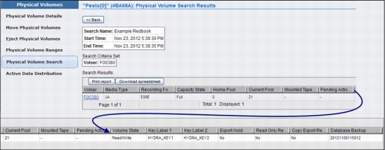
Figure 8-84 Physical Volume Search Results page
To check the progress of the search being run, click the Previous Search Results hyperlink in the information message. To cancel a search in progress, click Cancel Search. When the search completes, the results are displayed in the Physical Volume Search Results page. The query name, criteria, start time, and end time are saved along with the search results. You can save a maximum of 10 search queries.
Active Data Distribution
Use this page to view the distribution of data on physical volumes marked full on an IBM TS7720T and TS7740 Virtualization Engine Cluster. The distribution can be used to select an appropriate reclaim threshold.
The Active Data Distribution page displays the Utilization Percentages of physical volumes in increments of 10%.
Figure 8-85 shows the Active Data Distribution page.

Figure 8-85 Active Data Distribution window
Number of Full Volumes at Utilization Percentages
The tables in Figure 8-86 show the number of physical volumes that are marked as full in each physical volume pool, according to % of volume used. The following fields are displayed:
Pool The physical volume pool number. This number is a hyperlink; click it to display a graphical representation of the number of physical volumes per utilization increment in a pool. When you click the pool number hyperlink, the Active Data Distribution subpage opens.
Figure 8-86 shows a sample of the window you see by clicking the pool 4 hyperlink.

Figure 8-86 Active Data Distribution for a specific pool
This subpage contains the following fields and information:
Pool To view graphical information for another pool, select the target pool from this menu.
Current Reclaim Threshold
The percentage used to determine when to perform reclamation of free storage on a stacked volume. When the amount of active data on a physical stacked volume drops under this percentage, a reclaim operation is performed on the stacked volume. The valid range of possible values is 0 - 95% and can be selected in 5% increments; 35% is the default value.
The percentage used to determine when to perform reclamation of free storage on a stacked volume. When the amount of active data on a physical stacked volume drops under this percentage, a reclaim operation is performed on the stacked volume. The valid range of possible values is 0 - 95% and can be selected in 5% increments; 35% is the default value.
|
Tip: This percentage is a hyperlink; click it to open the Modify Pool Properties page, where you can modify the percentage that is used for this threshold.
|
Number of Volumes with Active Data
The number of physical volumes that contain active data.
The number of physical volumes that contain active data.
Pool n Active Data Distribution
This graph displays the number of volumes that contain active data per volume utilization increment for the selected pool. On this graph, utilization increments (x axis) do not overlap.
This graph displays the number of volumes that contain active data per volume utilization increment for the selected pool. On this graph, utilization increments (x axis) do not overlap.
Pool n Active Data Distribution (cumulative)
This graph displays the cumulative number of volumes that contain active data per volume utilization increment for the selected pool. On this graph, utilization increments (x axis) overlap, accumulating as they increase.
This graph displays the cumulative number of volumes that contain active data per volume utilization increment for the selected pool. On this graph, utilization increments (x axis) overlap, accumulating as they increase.
The Active Data Distribution subpage also displays utilization percentages for the selected pool, excerpted from the Number of Full Volumes at Utilization Percentages table.
Media Type The type of cartridges contained in the physical volume pool. If more than one media type exists in the pool, each type is displayed, separated by commas. The following values are possible:
Any 3592 Any media with a 3592 format
JA Enterprise Tape Cartridge (ETC)
JB Extended Data Enterprise Tape Cartridge (ETCL)
JC Enterprise Advanced Data Cartridge (EADC)
JJ Enterprise Economy Tape Cartridge (EETC)
JK Enterprise Advanced Economy Tape Cartridge (EAETC)
Percentage of Volume Used (0+, 10+, 20+, and so on)
Each of the last 10 columns in the table represents a 10% increment of total physical volume space used. For instance, the column heading 20+ represents the 20% - 29% range of a physical volume used. For each pool, the total number of physical volumes that occur in each range is listed.
Each of the last 10 columns in the table represents a 10% increment of total physical volume space used. For instance, the column heading 20+ represents the 20% - 29% range of a physical volume used. For each pool, the total number of physical volumes that occur in each range is listed.
Physical Tape Drives
Use this page to view a summary of the state of all physical drives accessible to the IBM TS7720T or TS7740 Virtualization Engine Cluster.
This page is visible but disabled on the TS7700 Virtualization Engine MI if the grid possesses a physical library, but the selected cluster does not. The following message is displayed:
The cluster is not attached to a physical tape library.
|
Tip: This page is not visible on the TS7700 Virtualization Engine MI if the grid does not possess a physical library.
|
Figure 8-87 shows the Physical Tape Drives page.
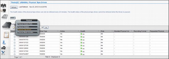
Figure 8-87 Physical Tape Drives page
The Physical Tape Drives table displays status information for all physical drives accessible by the cluster, including the following information:
Serial Number The serial number of the physical drive.
Drive Type The machine type and model number of the drive. The following values are possible:
3592J1A
3592E05
3592E05E A 3592 E05 drive that is encryption capable.
3592E06
3952E07
Online Whether the drive is online.
Health The health of the physical drive. This value is obtained automatically at times determined by the TS7700 Virtualization Engine. The following values are possible:
OK The drive is fully functioning.
WARNING The drive is functioning but reporting errors. Action needs to be taken to correct the errors.
DEGRADED The drive is operational but has lost some redundancy resource and performance.
FAILURE The drive is not functioning and immediate action must be taken to correct it.
OFFLINE/TIMEOUT The drive is out of service or unreachable within a certain time frame.
Role The current role the drive is performing. The following values are possible:
IDLE The drive is not in use.
MIGRATION The drive is being used to copy a virtual volume from the TVC to the physical volume.
RECALL The drive is being used to recall a virtual volume from a physical volume to the TVC.
RECLAIM SOURCE The drive is being used as the source of a reclaim operation.
RECLAIM TARGET The drive is being used as the target of a reclaim operation.
EXPORT The drive is being used to export a volume.
SECURE ERASE The drive is being used to erase expired volumes from the physical volume securely and permanently.
Mounted Physical Volume
VOLSER of the physical volume mounted by the drive.
VOLSER of the physical volume mounted by the drive.
Recording Format The format in which the drive operates. The following values are possible:
J1A The drive is operating with J1A data.
E05 The drive is operating with E05 data.
E05E The drive is operating with E05E encrypted data.
E06 The drive is operating with E06 data.
E06E The drive is operating with E06E encrypted data.
E07 The drive is operating with E07 data.
E07E The drive is operating with E07E encrypted data.
Not Available The format is unable to be determined because there is no physical media in the drive or the media is being erased.
Unavailable The format is unable to be determined because the Health and Monitoring checks have not yet completed. Refresh the current page to determine whether the format state has changed. If the Unknown state persists for one hour or longer, contact your IBM SSR.
Requested Physical Volume
The VOLSER of the physical volume requested for mount. If no physical volume is requested, this field is blank.
The VOLSER of the physical volume requested for mount. If no physical volume is requested, this field is blank.
To view additional information for a specific, selected drive, see the Physical Drives Details table on the Physical Tape Drive Details page:
1. Click the radio button next to the serial number of the physical drive in question.
2. Select Details from the Select Action menu.
3. Click Go to open the Physical Tape Drives Details page.
Figure 8-88 shows a Physical Tape Drive Details window.

Figure 8-88 Physical Tape Drive Details window
The Physical Drives Details table displays detailed information for a specific physical tape drive:
Serial Number The serial number of the physical drive.
Drive Type The machine type and model number of the drive. The following values are possible:
3592J1A
3592E05
3592E05E A 3592 E05 drive that is encryption capable.
3592E06
3952E07
Online Whether the drive is online.
Health The health of the physical drive. This value is obtained automatically at times determined by the TS7740 Virtualization Engine. The following values are possible:
OK The drive is fully functioning.
WARNING The drive is functioning but reporting errors. Action needs to be taken to correct the errors.
DEGRADED The drive is functioning but at lesser redundancy and performance.
FAILURE The drive is not functioning and immediate action must be taken to correct it.
OFFLINE/TIMEOUT The drive is out of service or cannot be reached within a certain time frame.
Role The current role that the drive is performing. The following values are possible:
IDLE The drive is not in use.
MIGRATION The drive is being used to copy a virtual volume from the TVC to the physical volume.
RECALL The drive is being used to recall a virtual volume from a physical volume to the TVC.
RECLAIM SOURCE The drive is being used as the source of a reclaim operation.
RECLAIM TARGET The drive is being used as the target of a reclaim operation.
EXPORT The drive is being used to export a volume.
SECURE ERASE The drive is being used to erase expired volumes from the physical volume securely and permanently.
Mounted Physical Volume
VOLSER of the physical volume mounted by the drive.
VOLSER of the physical volume mounted by the drive.
Recording Format The format in which the drive operates. The following values are possible:
J1A The drive is operating with J1A data.
E05 The drive is operating with E05 data.
E05E The drive is operating with E05E encrypted data.
E06 The drive is operating with E06 data.
E06E The drive is operating with E06E encrypted data.
E07 The drive is operating with E07 data.
E07E The drive is operating with E07E encrypted data.
Not Available The format is unable to be determined because there is no physical media in the drive or the media is being erased.
Unavailable The format is unable to be determined because the Health and Monitoring checks have not yet completed. Refresh the current page to determine whether the format state has changed. If the Unknown state persists for one hour or longer, contact your IBM SSR.
Requested Physical Volume
The VOLSER of the physical volume requested for mount. If no physical volume is requested, this field is blank.
The VOLSER of the physical volume requested for mount. If no physical volume is requested, this field is blank.
WWNN The worldwide node name used to locate the drive.
Frame The frame in which the drive resides.
Row The row in which the drive resides.
Encryption Enabled Whether encryption is enabled on the drive.
|
Note: If you are monitoring this field while changing the encryption status of a drive, the new status will not display until you bring the TS7700 Cluster offline and then return it to an online state.
|
Encryption Capable Whether the drive is capable of encryption.
Physical Volume VOLSER of the physical volume mounted by the drive.
Pool The pool name of the physical volume mounted by the drive.
Virtual Volume VOLSER of the virtual volume being processed by the drive.
4. Click Back to return to the Physical Tape Drives page.
Physical Media Inventory
Use this page to view physical media counts for media types in storage pools in the IBM TS7700 Virtualization Engine.
This page is visible but disabled on the TS7700 Virtualization Engine MI if the grid possesses a physical library, but the selected cluster does not. The following message is displayed:
The cluster is not attached to a physical tape library.
|
Tip: This page is not visible on the TS7700 Virtualization Engine MI if the grid does not possess a physical library.
|
Figure 8-89 shows the Physical Media Inventory page.
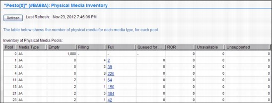
Figure 8-89 Physical Media Inventory page
The following physical media counts are displayed for each media type in each storage pool:
Pool The storage pool number.
Media Type The media type defined for the pool. A storage pool can have multiple media types and each media type is displayed separately. The following values are possible:
JA Enterprise Tape Cartridge (ETC)
JB Extended Data Enterprise Tape Cartridge (ETCL)
JC Enterprise Advanced Data Cartridge (EADC)
JJ Enterprise Economy Tape Cartridge (EETC)
JK Enterprise Advanced Economy Tape Cartridge (EAETC)
Empty The count of physical volumes that are empty for the pool.
Filling The count of physical volumes that are filling for the pool. This field is blank for pool 0.
Full The count of physical volumes that are full for the pool. This field is blank for pool 0.
|
Tip: A value in the Full field is displayed as a hyperlink; click it to open the Active Data Distribution subpage. The Active Data Distribution subpage displays a graphical representation of the number of physical volumes per utilization increment in a pool. If no full volumes exist, the hyperlink is disabled.
|
Queued for Erase The count of physical volumes that are reclaimed but need to be erased before they can become empty. This field is blank for pool 0.
ROR The count of physical volumes in the Read Only Recovery (ROR) state that are damaged or corrupted.
Unavailable The count of physical volumes that are in the unavailable or destroyed state.
Unsupported Unsupported media (for example: JA and JJ) type present in tape library and inserted for the TS7740 and TS7720T. Based on the drive configuration, the TS7700 cannot use one or more of the specified media, which can result in the out-of-scratch condition.
8.2.8 The Constructs icon
The topics in this section present information that is related to TS7700 Virtualization Engine storage constructs. Figure 8-90 shows you the Constructs icon and the options under it.

Figure 8-90 The Constructs icon
Storage Groups window
Use the window shown in Figure 8-91 to add, modify, or delete a Storage Group.

Figure 8-91 MI Storage Groups window
The Storage Groups table displays all existing Storage Groups available for a cluster.
You can use the Storage Groups table to create a new Storage Group, modify an existing Storage Group, or delete a Storage Group. Also, you can copy selected Storage Groups to the other clusters in this grid by using the Copy to Clusters action available in the menu.
The Storage Groups table shows the following status information:
Name The name of the Storage Group. Each Storage Group within a cluster must have a unique name. Valid characters for this field are A - Z, 0 - 9, $, @, *, #, and %.
Primary Pool The primary pool for migration. Only validated physical primary pools can be selected. If the cluster does not possess a physical library, this column is not visible, and the MI categorizes newly created Storage Groups using pool 1.
Description A description of the Storage Group.
Use the menu in the Storage Groups table to add a Storage Group, or modify or delete an existing Storage Group.
To add a Storage Group, select Add from the menu. Complete the fields for information that you want displayed in the Storage Groups table.
|
Restriction: If the cluster does not possess a physical library, the Primary Pool field is not available in the Add or Modify options.
|
To modify an existing Storage Group, select the radio button from the Select column that appears next to the name of the Storage Group that you want to modify. Select Modify
from the menu. Complete the fields for information that you want displayed in the Storage Groups table.
from the menu. Complete the fields for information that you want displayed in the Storage Groups table.
To delete an existing Storage Group, select the radio button from the Select column that appears next to the name of the Storage Group you want to delete. Select Delete from the menu. You are prompted to confirm your decision to delete a Storage Group. If you select OK, the Storage Group is deleted. If you select No, your request to delete is canceled.
Management Classes window
Use this window (Figure 8-92) to define, modify, copy, or delete the Management Class that defines the TS7700 Virtualization Engine copy policy for volume redundancy. The table displays the copy policy in force for each component of the grid.

Figure 8-92 MI Management Classes window on a grid
The secondary copy pool column only shows in a TS7720T or TS7740 cluster. This is a requirement for using the Copy Export function.
Figure 8-93 shows the Management Classes options, including the new Time Delayed option introduced by R3.1 of the Licensed Internal Code.

Figure 8-93 Modify Management Classes options
You can use the Management Classes table to create, modify, and delete Management Classes. The default Management Class can be modified, but cannot be deleted. The default Management Class uses dashes (--------) for the symbolic name.
The Management Classes table shows the following status information:
Name The name of the Management Class. Valid characters for this field are A - Z, 0 - 9, $, @, *, #, and %. The first character of this field cannot be a number. This is the only field that cannot be modified after it is added.
Secondary Pool The target pool in the volume duplication. If the cluster does not possess a physical library, this column is not visible and the MI categorizes newly created Storage Groups using pool 0.
Description A description of the Management Class definition. The value in this field must be 1 - 70 characters in length.
Retain Copy Mode Whether previous copy policy settings on private (non-Fast Ready) logical volume mounts are retained.
Retain Copy mode prevents the copy modes of a logical volume from being refreshed by an accessing host device if the accessing cluster is not the same cluster that created the volume. When Retain Copy mode is enabled through the MI, previously assigned copy modes are retained and subsequent read or modify access does not refresh, update, or merge copy modes. This enables the original number of copies to be maintained.
Scratch Mount Candidate
Clusters that are listed under Scratch Mount Candidate are selected first for scratch mounts of the volumes that are associated with the management class. If no cluster is displayed, the scratch mount process selects among the available clusters in a random mode.
To add a Management Class, complete the following steps:
2. Complete the fields for information that you want displayed in the Management Classes table.
You can create up to 256 Management Classes per TS7700 Virtualization Engine Grid.
|
Remember: If the cluster does not possess a physical library, the Secondary Pool field is not available in the Add option.
|
The Copy Action option enables you to copy any existing Management Class to each cluster in the TS7700 Virtualization Engine Grid.
The following options are available in the Management Class:
No Copy No volume duplication occurs if this action is selected.
Rewind Unload (RUN)
Volume duplication occurs when the Rewind Unload command is received. The command will only return after the volume duplication completes successfully.
Volume duplication occurs when the Rewind Unload command is received. The command will only return after the volume duplication completes successfully.
Deferred Volume duplication occurs later based on the internal schedule of the copy engine.
Synchronous Copy Volume duplication is treated as host I/O and takes place before control is returned to the application issuing the I/O. Only two clusters in the grid can have the Synchronous mode copy defined.
Time Delayed Volume duplication will only occur after the delay time specified by the user elapses. This option is only available if all clusters in the grid are running R3.1 or higher level of code. Selecting Time Delayed Mode for any cluster opens another option menu:
Delay Queueing Copy for [X] Hours
Number of hours that queuing the copies will be delayed if Time Delayed Mode Copy is selected. Can be set for 1 - 65,535 hours.
Start Delay After:
Volume Create: Delay time is clocked from the volume creation.
Volume Last Accessed:
Delay time is clocked from the last access. Every time a volume is accessed, elapsed time is zeroed for that volume and countdown starts again from delay value set by user.
To modify an existing Management Class, complete the following steps:
1. Select the check box from the Select column that appears in the same row as the name of the Management Class that you want to modify.
You can only modify one Management Class at a time.
2. Select Modify from the menu and click Go.
Of the fields listed previously in the Management Classes table, you are able to change all of them except the Management Class name.
To delete one or more existing Management Classes, complete the following steps:
1. Select the check box from the Select column that appears in the same row as the name of the Management Class that you want to delete.
2. Select multiple check boxes to delete multiple Management Classes.
3. Select Delete from the menu.
4. Click Go.
|
Restriction: You cannot delete the default Management Class.
|
Storage Classes window
Use the window shown in Figure 8-94 to define, modify, or delete a Storage Class used by the TS7700 Virtualization Engine to automate storage management through classification of data sets and objects within a cluster. Also, this page can be used to copy an existing Storage Class to the same cluster being accessed, or to another cluster in the grid.
Storage classes can be viewed from any TS7700 in the grid, but Tape Volume Cache Preferences only can be altered from a tape attached cluster. Figure 8-94 shows the page in a TS7720T model, introduced with R3.2 of Licensed Internal Code.

Figure 8-94 MI Storage Classes window on a TS7720T
The Storage Classes table lists defined storage classes that are available to control data sets and objects within a cluster. Figure 8-95 shows the Create Storage Class box for the TS7720T compared to the TS7700 cluster.
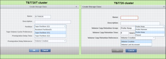
Figure 8-95 Create Storage Class box
The Storage Class page and the Create Storage Class box are pictured in Figure 8-96 as it shows in the TS7740 cluster.
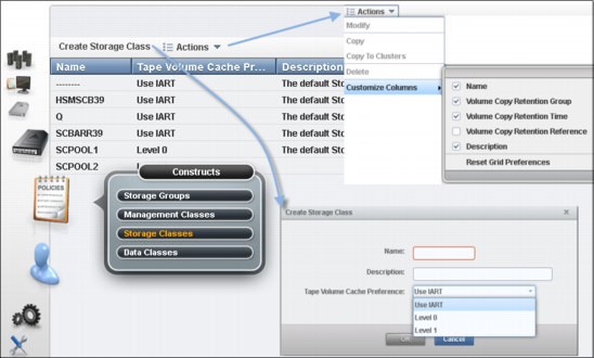
Figure 8-96 The Storage Classes page and Create Storage Class box for TS7740 cluster.
The default Storage Class can be modified, but cannot be deleted. The default Storage Class has dashes (--------) as the symbolic name.
The Storage Classes table displays the following status information:
•Name. The name of the storage class. The value in this field must be 1 - 8 characters in length. Each storage class within a cluster must have a unique name. Valid characters for this field are A-Z, 0-9, $, @, *, #, and %. The first character of this field cannot be a number. This is the only field that cannot be modified after it is added.
•Description. An optional description of the storage class. The value in this field must be
0 - 70 characters in length.
0 - 70 characters in length.
•Partition. The name of the partition associated with the Storage Class. A partition must be active before it can be selected as a value for this field. This field is only displayed if the cluster is a TS7720 attached to a physical library. Notice that a dash (-) indicates that the Storage Class contains a partition that has been deleted. Any volumes that are assigned to go to the deleted partition are redirected to the primary tape partition.
•Tape Volume Cache Preference. The preference level for the storage class. It determines how soon volumes are removed from cache after their copy to tape. This field is visible only if the TS7700 Cluster attaches to a physical library. If the selected cluster does not possess a physical library, volumes in that cluster’s cache display a Level 1 preference. The following values are possible:
– Use IART. Volumes are removed according to the IBM TS7700’s Initial Access Response Time (IART).
– Level 0. Volumes are removed from the tape volume cache as soon as they are copied to tape.
– Level 1. Copied volumes remain in the tape volume cache until additional space is required, then are the first volumes removed to free space in the cache. This is the default preference level assigned to new preference groups.
•Premigration Delay Time. The number of hours until premigration can begin for volumes in the storage class, based on the volume time stamp designated by Premigration Delay Reference. Possible values are 0 - 65535. If 0 is selected, premigration delay is disabled. This field is visible only if the TS7700 Cluster attaches to a physical library.
•Premigration Delay Reference. The volume operation that establishes the time stamp from which Premigration Delay Time is calculated. This field is visible only if the TS7700 Cluster attaches to a physical library. The following values are possible:
– Volume Creation. The time at which the volume was created by a scratch mount or write operation from beginning of tape.
– Volume Last Accessed. The time at which the volume was last accessed.
•Volume Copy Retention Group. The name of the group that defines the preferred auto removal policy applicable to the virtual volume.
The Volume Copy Retention Group provides additional options to remove data from a disk-only TS7720 or resident-only (CP0) partition in the TS7720T as the active data reaches full capacity. Volumes become candidates for removal if an appropriate number of copies exist on peer clusters and the volume copy retention time has elapsed since the volume was last accessed. Volumes in each group are removed in order based on their least recently used access times.
The volume copy retention time describes the number of hours a volume remains in cache before becoming a candidate for removal. This field is displayed only if the cluster is a TS7720 cluster or part of a hybrid grid (one that combines TS7700 Clusters that both do and do not attach to a physical library).
If the virtual volume is in a scratch category and is on a disk-only cluster, removal settings no longer apply to the volume, and it is a candidate for removal. In this instance, the value displayed for the Volume Copy Retention Group is accompanied by a warning icon:
– Prefer Remove. Removal candidates in this group are removed before removal candidates in the Prefer Keep group.
– Prefer Keep. Removal candidates in this group are removed after removal candidates in the Prefer Remove group.
– Pinned. Copies of volumes in this group are never removed from the accessing cluster. The volume copy retention time does not apply to volumes in this group. Volumes in this group that are later moved to scratch become priority candidates for removal.
•Volume Copy Retention Time. The minimum amount of time (in hours) after a virtual volume copy was last accessed that the copy can be removed from cache. The copy is said to be expired after this time has passed, and the copy then becomes a candidate for removal. Possible values include 0 - 65,536; the default is 0.
This field is only visible if the selected cluster is a TS7720 and all of the clusters in the grid operate at microcode level 8.7.0.xx or later. If the Volume Copy Retention Group displays a value of Pinned, this field is disabled.
•Volume Copy Retention Reference. The volume operation that establishes the time stamp from which Volume Copy Retention Time is calculated. The following list describes the possible values:
– Volume Creation
The time at which the volume was created by a scratch mount or write operation from beginning of tape.
– Volume Last Accessed
The time at which the volume was last accessed.
If the Volume Copy Retention Group displays a value of Pinned, this field is disabled.
Data Classes window
Use the window shown in Figure 8-97 to define, modify, copy, or delete a TS7700 Virtualization Engine Data Class used to automate storage management through the classification of data sets, defining volume sizes and LWORM policy assignment.

Figure 8-97 MI Data Classes window
|
Important: Scratch (Fast Ready) categories and Data Classes work at the system level and are unique for all clusters in a grid. Therefore, if you modify them on one cluster, they are applied to all clusters in the grid.
|
The Data Classes table (Figure 8-97) displays the list of Data Classes defined for each cluster of the grid.
You can use the Data Classes table to create a new Data Class or modify, copy, or delete an existing Data Class. The default Data Class can be modified, but cannot be deleted. The default Data Class has dashes (--------) as the symbolic name.
The Data Classes table lists the following status information:
Name The name of the Data Class. Valid characters for this field are A - Z,
0 - 9, $, @, *, #, and %. The first character of this field cannot be a number. The value in this field must be 1 - 8 characters in length. The first character of this field cannot be a number. This field is the only field that cannot be modified after it is added.
0 - 9, $, @, *, #, and %. The first character of this field cannot be a number. The value in this field must be 1 - 8 characters in length. The first character of this field cannot be a number. This field is the only field that cannot be modified after it is added.
Virtual Volume Size (MiB)
The logical volume size of the Data Class, which determines the maximum number of MiB for each logical volume in a defined class. One possible value is Insert Media Class, where the logical volume size is not defined (the Data Class is not defined by a maximum logical volume size). Other possible values are 1,000 MiB, 2,000 MiB, 4,000 MiB, 6,000 MiB, or 25,000 MiB.
The logical volume size of the Data Class, which determines the maximum number of MiB for each logical volume in a defined class. One possible value is Insert Media Class, where the logical volume size is not defined (the Data Class is not defined by a maximum logical volume size). Other possible values are 1,000 MiB, 2,000 MiB, 4,000 MiB, 6,000 MiB, or 25,000 MiB.
A maximum size of 25,000 MiB for logical volumes is allowed without any restriction if all clusters in a grid operate at R3.2 level of Licensed Internal Code.
Otherwise, the 25,000 MiB is not supported whenever one or more TS7740 clusters are present in grid, and at least one cluster in the grid operates at a Licensed Internal Code level earlier than R3.2.
Also, being the grid formed exclusively by TS7720 clusters that are not attached to a physical library, Feature Code 0001 is required on every cluster operating at a LIC level earlier than R3.2.
Description A description of the Data Class definition. The value in this field must be 0 - 70 characters in length.
Logical WORM Whether logical WORM is set for the Data Class. Logical WORM is the virtual equivalent of WORM tape media, achieved through software emulation. This setting is available only when all clusters in a grid operate at R1.6 and later.
The following values are valid:
Yes Logical WORM is set for the Data Class. Volumes belonging to the Data Class are defined as logical WORM.
No Logical WORM is not set. Volumes belonging to the Data Class are not defined as logical WORM. This is the default value for a new Data Class.
Use the menu in the Data Classes table to add a Data Class, or modify or delete an existing Data Class.
|
Tip: You can create up to 256 Data Classes per TS7700 Virtualization Engine Grid.
|
8.2.9 The Access icon
The topics in this section present information that is related to managing user access in a TS7700 Virtualization Engine. A series of enhancements in user access management has been introduced. TS7700 Virtualization Engine Release 1.6 brought in a centrally managed, role-based access control (RBAC) policy that authenticated and authorized users by using the System Storage Productivity Center (SSPC). The SSPC was the logical component which ultimately authenticated the TS7700 users to an LDAP server.
Beginning with Release 3.0 of LIC, the TS7700 Virtualization Engine can authenticate users directly to an LDAP server (Microsoft Active Directory), not depending on the SSPC as intermediary. Authenticating through an SSPC is still supported, though.
|
Note: Before Release 3.0 (from R1.6 to R2.1), RBAC policies applied only to the MI.
|
Also in R3.0, RBAC policies (when active) apply to all users, through all access ports to the TS7700. Therefore, if centrally managed RBAC is applied (either with SSPC, direct LDAP server, or RACF) no one can log in to the TS7700 Virtualization Engine without being authenticated and authorized by the LDAP server. Even a local IBM SSR, operating from the TS3000 System Console (TSSC), is required to use the LDAP-defined service login. This also applies to remote support, using a telephone line or Assist On-site (AOS) session.
R3.2 makes an option available to the user to exclude IBM Service Representative (local and remote) from RBAC policies by selecting a box in the Management Interface, as shown in Figure 8-115 on page 433.
|
Note: Define a user account for service, or select the boxes to enable IBM service personnel to log in to the machine (local and remote) before enabling external policies.
|
Now, in addition to the Microsoft Active Directory authentication method, R3.2 of Licensed Internal Code enables all user accesses to the TS7700 clusters to be secured and controlled by the Resource Access Control Facility (RACF), which is the standard security product to manage access control in a System z environment.
Although Resource Access Control Facility is intended to address all of the secure access needs for the System z environment, RACF does not provide a direct interface for the external storage devices, such as the TS7700 cluster. The current implementation uses the Tivoli LDAP server for System z as a bridge between the TS7700 clusters and RACF. The authentication policies can be classified into two categories:
•Local, which replicates users and respective assigned roles across the grid.
•External, which keeps the list of users and group data on a separated server, mapping the relationship between users, group, and authorization roles when a user logs in to a cluster.
External authentication policies include Storage Authentication Service policies and Direct LDAP (lightweight directory access protocol) policies.
|
Important: Before enabling External policies, create an account that can be used by service personnel (local and remote), or select the boxes in MI to exclude IBM Service Representative (local and remote) from RBAC policies.
|
Local Authentication Policy is managed and applied within the cluster or clusters participating in a grid. In a multicluster grid configuration, user IDs and their associated roles are defined through the MI on one of the clusters. The user IDs and roles are then propagated through the grid to all participating clusters. Storage Authentication Service and Direct LDAP policies enable you to centrally manage user IDs and roles:
•The Storage Authentication Service policy stores user and group data on a separate server and maps relationships among users, groups, and authorization roles when a user signs in to a cluster. Network connectivity to an external System Storage Productivity Center (SSPC) is required. Each cluster in a grid can operate its own Storage Authentication Service policy.
•Direct LDAP policy is an RBAC policy that authenticates and authorizes users through direct communication with an LDAP (Microsoft Active Directory platform) server or Tivoli LDAP server for System z. Only one authentication policy can be enabled per cluster at one time.
RACF authentication, introduced with TS7700 R3.2 of Licensed Internal Code, uses the Secure Database Manager (SDBM) into Tivoli LDAP server for System z as a front end to the RACF (Resource Access Control Facility).
You can access the following options through the User Access (blue man icon) link:
Security Settings Use this window to view security settings for a TS7700 Virtualization Engine Grid. From this page, you can also access windows to add, modify, assign, test, and delete security settings.
Roles and Permissions
Use this window to set and control user roles and permissions for a TS7700 Virtualization Engine Grid.
Use this window to set and control user roles and permissions for a TS7700 Virtualization Engine Grid.
SSL Certificates Use this window to view, import, or delete Secure Sockets Layer (SSL) certificates to support connection to a Storage Authentication Service server from a TS7700 Virtualization Engine Cluster.
InfoCenter Settings Use this page to upload a new TS7700 Virtualization Engine Information Center to the cluster’s MI.
The options for User Access Management in the MI for TS7700 Virtualization Engine are shown in Figure 8-98.
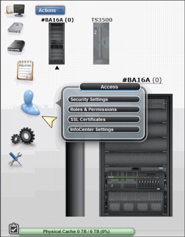
Figure 8-98 TS7700 Virtualization Engine User Access Management options
Security Settings
Figure 8-99 shows the Security Settings window, which is the entry point to enabling security policies.

Figure 8-99 TS7700 Security Settings
Use the Session Timeout policy to specify the number of hours and minutes that the MI can be idle before the current session expires and the user is redirected to the login page. This setting is valid for all users in the grid.
To modify the maximum idle time, select values from the Hours and Minutes menus and click Submit Changes. The following parameters are valid for Hours and Minutes:
Hours The number of hours the MI can be idle before the current session expires. Possible values for this field are 00 - 23.
Minutes The number of minutes the MI can be idle before the current session expires. Possible values for this field are 00 - 55, selected in 5-minute increments.
The Authentication Policies table lists the following information:
Policy Name The name of the policy that defines the authentication settings. The policy name is a unique value composed of 1 - 50 Unicode characters. Heading and trailing blank spaces are trimmed, although internal blank spaces are retained. After a new authentication policy is created, its policy name cannot be modified.
|
Tip: The Local Policy name is Local and cannot be modified.
|
Type The policy type, which can be one of the following values:
Local A policy that replicates authorization based on user accounts and assigned roles. It is the default authentication policy. When enabled, it is enforced for all clusters in the grid. If Storage Authentication Service is enabled, the Local policy is disabled. This policy can be modified to add, change, or delete individual accounts, but the policy itself cannot be deleted.
Storage Authentication Service
A policy that maps user, group, and role relationships upon user login. Each cluster in a grid can operate its own Storage Authentication Service policy by using assignment.
A policy that maps user, group, and role relationships upon user login. Each cluster in a grid can operate its own Storage Authentication Service policy by using assignment.
However, only one authentication policy can be enabled on any particular cluster within the grid, even if the same policy is used within other clusters of the same grid domain. A Storage Authentication Service policy can be modified, but can only be deleted if it is not in use on any cluster in the grid.
Clusters The clusters for which the authentication policy is in force.
Adding a user to the Local Authentication Policy
A Local Authentication Policy replicates authorization based on user accounts and assigned roles. It is the default authentication policy. This section looks at the various windows required to manage the Local Authentication Policy.
To add a user to the Local Authentication Policy for a TS7700 Virtualization Engine Grid, complete the following steps:
1. On the TS7700 Virtualization Engine MI, select Access → Security Settings from the left navigation window.
2. Click Select next to the Local policy name on the Authentication Policies table.
3. Select Modify from the Select Action menu and click Go.
4. On the Local Accounts table, select Add from the Select Action menu and click Go.
5. In the Add User window, enter values for the following required fields:
– User name: The new user’s login name. This value must be 1 - 128 characters in length and composed of Unicode characters. Spaces and tabs are not allowed.
– Role: The role assigned to the user account. The role can a predefined role or a user-defined role. The following values are possible:
• Operator: The operator has access to monitoring information, but is restricted from changing settings for performance, network configuration, feature licenses, user accounts, and custom roles. The operator is also restricted from inserting and deleting logical volumes.
• Lead Operator: The lead operator has access to monitoring information and can perform actions for a volume operation. The lead operator has nearly identical permissions to the administrator, but cannot change network configuration, feature licenses, user accounts, or custom roles.
• Administrator: The administrator has the highest level of authority, and can view all pages and perform any action, including the addition and removal of user accounts. The administrator has access to all service functions and TS7700 Virtualization Engine resources.
• Manager: The manager has access to monitoring information, and performance data and functions, and can perform actions for users, including adding, modifying, and deleting user accounts. The manager is restricted from changing most other settings, including those for logical volume management, network configuration, feature licenses, and custom roles.
• Custom roles: The administrator can name and define two custom roles by selecting the individual tasks that are permitted to each custom role. Tasks can be assigned to a custom role in the Roles and assigned permissions table in the Roles & Permissions Properties window.
– Cluster Access: The clusters to which the user has access. A user can have access to multiple clusters.
6. To complete the operation, click OK. To abandon the operation and return to the Modify Local Accounts window, click Cancel.
Figure 8-100 shows the first window for creating a new user. It is used for managing users with the Local Authentication Policy method.

Figure 8-100 Creating a user (part 1of 2)
Figure 8-101 shows the second window for creating a user.

Figure 8-101 Creating a user (part 2 of 2)
Modifying the user or group of the Local Authentication Policy
Use this window to modify a user or group property for a TS7700 Virtualization Engine Grid.
|
Tip: Passwords for the users are changed from this window also.
|
To modify a user account belonging to the Local Authentication Policy, complete these steps:
1. On the TS7700 Virtualization Engine MI, select Access (blue man icon) → Security Settings from the left navigation window. See Figure 8-101 and Figure 8-100 on page 419 for the MI windows.
2. Click Select next to the Local policy name on the Authentication Policies table.
3. Select Modify from the Select Action menu and click Go.
4. On the Local Accounts table, click Select next to the user name of the policy that you want to modify.
5. Select Modify from the Select Action menu and click Go. See Figure 8-101 for the Modify Local Accounts options.
6. Modify the values for any of the following fields:
– Role: The role that is assigned to the user account. The following values are possible:
• Operator: The operator has access to monitoring information, but is restricted from changing settings for performance, network configuration, feature licenses, user accounts, and custom roles. The operator is also restricted from inserting and deleting logical volumes.
• Lead Operator: The lead operator has access to monitoring information and can perform actions for volume operation. The lead operator has nearly identical permissions to the administrator, but cannot change network configuration, feature licenses, user accounts, and custom roles.
• Administrator: The administrator has the highest level of authority, and can view all pages and perform any action, including the addition and removal of user accounts. The administrator has access to all service functions and TS7700 Virtualization Engine resources.
• Manager: The manager has access to monitoring information and performance data and functions, and can perform actions for users, including adding, modifying, and deleting user accounts. The manager is restricted from changing most other settings, including those for logical volume management, network configuration, feature licenses, and custom roles.
• Custom roles: The administrator can name and define two custom roles by selecting the individual tasks permitted to each custom role. Tasks can be assigned to a custom role in the Roles and assigned permissions table from the Roles & Permissions Properties window.
– Cluster Access: The clusters to which the user has access. A user can have access to multiple clusters.
7. To complete the operation, click OK. To abandon the operation and return to the Modify Local Accounts page, click Cancel.
|
Restriction: You cannot modify the user name or Group Name. Only the role and the clusters to which it is applied can be modified.
|
The Modify Local Account window is shown in Figure 8-101 on page 420. In the Cluster Access table, you can use the Select check box to toggle all the cluster check boxes on
and off.
and off.
Adding a Storage Authentication Service policy
A Storage Authentication Service Policy maps user, group, and role relationships upon user login with the assistance of a System Storage Productivity Center (SSPC). This section highlights the various windows that are required to manage the Storage Authentication Service Policy.
|
Important: When a Storage Authentication Service policy is enabled for a cluster, service personnel are required to log in with the setup user or group. Before enabling storage authentication, create an account that can be used by service personnel.
|
To add a Storage Authentication Service Policy for a TS7700 Virtualization Engine Grid, complete the following steps:
1. On the TS7700 Virtualization Engine MI, select Access (blue man icon) → Security Settings from the left navigation window.
2. On the Authentication Policies table, select Add Storage Authentication Service Policy from the Select Action menu.
3. Click Go to open the Add Storage Authentication Service Policy window shown in Figure 8-102 on page 422. The following fields are available for completion:
a. Policy Name: The name of the policy that defines the authentication settings. The policy name is a unique value composed of 1 - 50 Unicode characters. Heading and trailing blank spaces are trimmed, although internal blank spaces are retained. After a new authentication policy is created, its policy name cannot be modified.
b. Primary Server URL: The primary URL for the Storage Authentication Service. The value in this field consists of 1 - 256 Unicode characters and takes the following format:
https://<server_IP_address>:secure_port/TokenService/services/Trust
c. Alternative Server URL: The alternative URL for the Storage Authentication Service if the primary URL cannot be accessed. The value in this field consists of 1 - 256 Unicode characters and takes the following format:
https://<server_IP_address>:secure_port/TokenService/services/Trust
|
Remember: If the Primary or alternative Server URL uses the HTTPS protocol, a certificate for that address must be defined on the SSL Certificates page.
|
d. Server Authentication: Values in the following fields are required if IBM WebSphere Application Server security is enabled on the WebSphere Application Server that is hosting the Authentication Service. If WebSphere Application Server security is disabled, the following fields are optional:
• User ID: The user name used with HTTP basic authentication for authenticating to the Storage Authentication Service.
• Password: The password used with HTTP basic authentication for authenticating to the Storage Authentication Service.
4. To complete the operation, click OK. To abandon the operation and return to the Security Settings page, click Cancel.
Figure 8-102 shows an example of a completed Add Storage Authentication Service Policy window.

Figure 8-102 Add Storage Authentication Service Policy
After you click OK to confirm the creation of the new Storage Authentication Policy, the window shown in Figure 8-103 opens. In the Authentication Policies table, no clusters are assigned to the newly created policy, so the Local Authentication Policy is enforced. When the newly created policy is in this state, it can be deleted because it is not applied to any of the clusters.
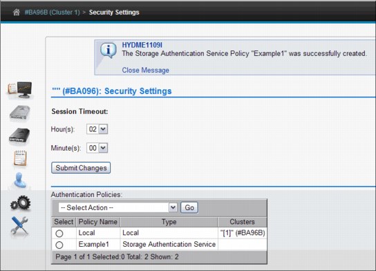
Figure 8-103 Addition of Storage Authentication Service Policy completed
Adding a user to a Storage Authentication Policy
To add a user to a Storage Authentication Service Policy for a TS7700 Virtualization Engine Grid, complete the following steps:
1. On the TS7700 Virtualization Engine MI, select Access → Security Settings from the left navigation window.
2. In the Authentication Policies table, select Modify from the Select Action menu as shown in Figure 8-104.

Figure 8-104 Selecting Modify Security Settings

Figure 8-105 Adding a User to the Storage Authentication Service Policy
4. In the Modify Storage Authentication Service Policy window in Figure 8-105, go to the Storage Authentication Service Users/Groups table at the bottom.
5. Select Add User from the Select Action menu.

Figure 8-106 Defining user name, Role, and Cluster Access permissions
7. In the Add External Policy User window, enter values for the following required fields:
– User name: The new user’s login name. This value must be 1 - 128 characters in length and composed of Unicode characters. Spaces and tabs are not allowed.
– Role: The role assigned to the user account. The role can be a predefined role or a user-defined role. The following values are valid:
• Operator: The operator has access to monitoring information, but is restricted from changing settings for performance, network configuration, feature licenses, user accounts, and custom roles. The operator is also restricted from inserting and deleting logical volumes.
• Lead Operator: The lead operator has access to monitoring information and can perform actions for a volume operation. The lead operator has nearly identical permissions as the administrator, but cannot change network configuration, feature licenses, user accounts, and custom roles.
• Administrator: The administrator has the highest level of authority, and can view all pages and perform any action, including the addition and removal of user accounts. The administrator has access to all service functions and TS7700 Virtualization Engine resources.
• Manager: The manager has access to monitoring information and performance data and functions, and can perform actions for users, including adding, modifying, and deleting user accounts. The manager is restricted from changing most other settings, including those for logical volume management, network configuration, feature licenses, and custom roles.
• Custom roles: The administrator can name and define two custom roles by selecting the individual tasks permitted to each custom role. Tasks can be assigned to a custom role in the Roles and assigned permissions table in the Roles & Permissions Properties window.
– Cluster Access: The clusters (can be multiple) to which the user has access.
8. To complete the operation, click OK. To abandon the operation and return to the Modify Local Accounts page, click Cancel.
9. Click OK after the fields are complete. A user is added to the Storage Authentication Service Policy as shown in Figure 8-107.
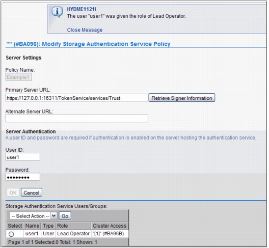
Figure 8-107 Successful addition of user name to Storage Authentication Service Policy
Assigning clusters to a Storage Authentication Policy
Clusters participating in a multicluster grid can have unique Storage Authentication policies active. To assign an authentication policy to one or more clusters, you must have authorization to modify authentication privileges under the new policy. To verify that you have sufficient privileges with the new policy, you must enter a user name and password recognized by the new authentication policy.
To add a user to a Storage Authentication Service Policy for a TS7700 Virtualization Engine Grid, complete the following steps:
1. On the TS7700 Virtualization Engine MI, select Access → Security Settings from the left navigation window.
2. In the Authentication Policies table, select Assign from the Select Action menu as shown in Figure 8-108.
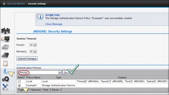
Figure 8-108 Assigning Storage Authentication Service Policy to grid resources
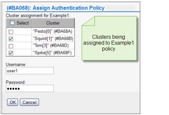
Figure 8-109 Cluster assignment selection for Storage Authentication Service Policy
4. To apply the authentication policy to a cluster, select the check box next to the cluster’s name.
Enter values for the following fields:
– User name: Your user name for the TS7700 Virtualization Engine MI.
– Password: Your password for the TS7700 Virtualization Engine MI.
5. To complete the operation, click OK. To abandon the operation and return to the Security Settings window, click Cancel.
Deleting a Storage Authentication Policy
You can delete a Storage Authentication Service policy if it is not in effect on any cluster. You cannot delete the Local policy. In the Authentication Policies table in Figure 8-110, no clusters are assigned to the policy, so it can be deleted. If clusters are assigned to the policy, use Modify from the Select Action menu to remove the assigned clusters.

Figure 8-110 Deleting a Storage Authentication Service Policy
To delete a Storage Authentication Service Policy from a TS7700 Virtualization Engine Grid, complete the following steps:
1. On the TS7700 Virtualization Engine MI, select Access → Security Settings from the left navigation window.
2. In the Authentication Policies table, select Delete go to the Select Action menu as shown in Figure 8-110. From the Security Settings page, go to the Authentication Policies table and complete the following steps:
a. Select the radio button next to the policy you want to delete.
b. Select Delete from the Select Action menu.
c. Click Go to open the Confirm Delete Storage Authentication Service policy window.
d. Click OK to delete the policy and return to the Security Settings window, or click Cancel to abandon the delete operation and return to the Security Settings window.
You are asked to confirm the policy deletion, as shown in Figure 8-111. Click OK to delete
the policy.
the policy.
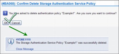
Figure 8-111 Confirm delete and delete action successful messages
Testing an Authentication Policy
Before a new Authentication Policy can be used, it must be tested. The test validates the login credentials (user ID and password) in all clusters for which this user ID and role are authorized. Also, access to the external resources needed by an external authentication policy, such as an SSPC or an LDAP server, is tested. The credentials entered in the test window (User ID and Password) are authenticated and validated by the LDAP server, for an external policy.
|
Tip: The policy needs to be configured to an LDAP server before being added in the TS7700 MI. External users and groups to be mapped by the new policy are checked in LDAP before being added.
|
Follow the procedure described next to test the security settings for the IBM TS7700 Virtualization Engine Grid. Use these steps to test the roles assigned to your user name by an existing policy:
1. From the Security Settings page, go to the Authentication Policies table:
– Select the radio button next to the policy that you want to test.
– Select Test from the Select Action menu.
– Click Go to open the Test Authentication Policy page.
2. Check the check box next to the name of each cluster on which to conduct the policy test.
3. Enter values for the following fields:
– User name: Your user name for the TS7700 Virtualization Engine MI. This value consists of 1 - 16 Unicode characters.
– Password: Your password for the TS7700 Virtualization Engine MI. This value consists of 1- 16 Unicode characters.
|
Note: If the user name entered belongs to a user not included on the policy, test results show success, but the result comments show a null value for the role and access fields. Additionally, the user name entered cannot be used to log in to the MI.
|
4. Click OK to complete the operation. If you want to abandon the operation, click Cancel to return to the Security Settings page.
When the authentication policy test completes, the Test Authentication Policy results window opens to display results for each selected cluster. See Figure 8-112 for an example.

Figure 8-112 Test Authentication Policy results
The results include a statement indicating whether the test succeeded or failed, and if it failed, the reason for the failure. The Test Authentication Policy results window also displays the Policy Users table. Information shown on that table includes the following fields:
User name The name of a user authorized by the selected authentication policy.
Role The role assigned to the user under the selected authentication policy.
Cluster Access A list of all the clusters in the grid for which the user and user role are authorized by the selected authentication policy. Check Figure 8-113 for an example of a failure in the Test Authentication Policy.

Figure 8-113 Failure in the Test Authentication Policy
To return to the Test Authentication Policy window, click Close Window. To return to the Security Settings page, click Back at the top of the Test Authentication Policy results window.
Adding a Direct LDAP policy
A Direct LDAP Policy is an external policy that maps user, group, and role relationships. Users are authenticated and authorized through a direct communication with an LDAP server. This section highlights the various windows that are required to manage a Direct LDAP policy.
|
Important: When a Direct LDAP policy is enabled for a cluster, service personnel are required to log in with the setup user or group. Before enabling LDAP authentication, create an account that can be used by service personnel. From R3.1 on, you can enable an IBM Service Representative to connect to your TS7700 through physical access or remotely by selecting those options in the DIRECT LDAP POLICY page.
|
To add a Direct LDAP Policy for a TS7700 Virtualization Engine Grid, complete the following steps:
1. On the TS7700 Virtualization Engine MI, select Access → Security Settings from the left navigation window.

Figure 8-114 Adding a Direct LDAP Policy selection
3. Use the options in Figure 8-115 to grant to the IBM Service Representative a local or remote connection for service support.
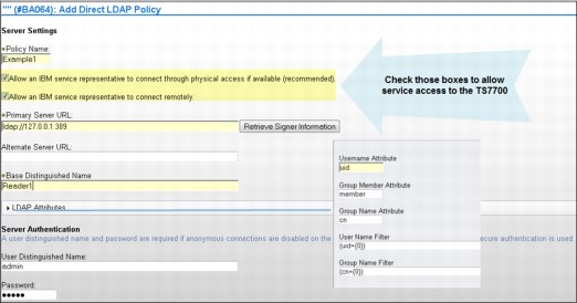
Figure 8-115 Adding a Direct LDAP Policy
|
Note: LDAP external authentication policies are not available for backup or recovery through the backup or restore settings operations. Record it, keep it safe, and have it available for a manual recovery as dictated by your security standards.
|
The values in the following fields are required if secure authentication is used or anonymous connections are disabled on the LDAP server:
•User Distinguished Name: The user distinguished name is used to authenticate to the LDAP authentication service. This field supports a maximum length of 254 Unicode characters, for example:
CN=Administrator,CN=users,DC=mycompany,DC=com
•Password: The password is used to authenticate to the LDAP authentication service. This field supports a maximum length of 254 Unicode characters.
If you selected to modify an LDAP Policy, you can also change any of these LDAP attributes fields:
•Base Distinguish Name: The LDAP distinguished name (DN) that uniquely identifies a set of entries in a realm. This field is required but blank by default. The value in this field consists of 1 - 254 Unicode characters.
•User Name Attribute: The attribute name used for the user name during authentication. This field is required and contains the value uid by default. The value in this field consists of 1 - 61 Unicode characters.
•Password: The attribute name used for the password during authentication. This field is required and contains the value userPassword by default. The value in this field consists of 1 - 61 Unicode characters.
•Group Member Attribute: The attribute name used to identify group members. This field is optional and contains the value member by default. This field can contain up to 61 Unicode characters.
•Group Name Attribute: The attribute name used to identify the group during authorization. This field is optional and contains the value cn by default. This field can contain up to 61 Unicode characters.
•User Name filter: Used to filter and verify the validity of an entered user name. This field is optional and contains the value (uid={0}) by default. This field can contain up to 254 Unicode characters.
•Group Name filter: Used to filter and verify the validity of an entered group name. This field is optional and contains the value (cn={0}) by default. This field can contain up to 254 Unicode characters.
Click OK to complete the operation. Click Cancel to abandon the operation and return to the Security Settings page.
Creating a RACF-based LDAP Policy
The process is similar to the previous item “Adding a Direct LDAP policy” on page 432. There are some required configurations on the host side regarding the RACF, SDBM, and Tivoli LDAP server that should be performed in advance before this capability can be made operational. See Chapter 9, “Host Console Operations” on page 567 for the description of the parameters and configurations. When those configurations are ready, the RACF-based LDAP Policy can be created and activated. See Figure 8-116 to add a RACF policy.

Figure 8-116 Adding a RACF based Direct LDAP Policy.
As shown in Figure 8-116, a new policy is created, here called RACF_LDAP. The Primary Server URL is that of the Tivoli LDAP server, the same way any regular LDAP server would be configured.
The Base Distinguished Name matches the SDBM_SUFFIX.
In the screen capture, the Group Member Attribute was set to racfgroupuserids (it shows truncated in MI’s text box).
The item User Distinguished Name should be specified with all of the following parameters:
•racfid
•profiletype
•cn
When the previous setup is complete, additional users can be added to the policy, or clusters can be assigned to it, as described in the topics to follow. There are no specific restrictions for these RACF/LDAP user IDs, and they can be used to secure the Management Interface, or the IBM service login (for the IBM service representative) just as any other LDAP user ID.
See the TS7700 3.2 IBM Knowledge Center, available locally on the MI page by clicking the question mark on the upper right upper bar and selecting Help, or on the following website:
Adding users to a Direct LDAP Policy
See the process described in the “Adding a user to a Storage Authentication Policy” on page 424. The same steps apply when adding users to a Direct LDAP Policy.
Assign a Direct LDAP Policy to a cluster or clusters
See the procedure described in “Assigning clusters to a Storage Authentication Policy” on page 427. The same steps apply when working with a Direct LDAP Policy.
Deleting a Direct LDAP Policy
See the procedure described in “Deleting a Storage Authentication Policy” on page 429. The same steps apply when deleting a Direct LDAP Policy.
Roles & Permissions window
You can use the window shown in Figure 8-117 to set and control user roles and permissions for a TS7700 Virtualization Engine Grid.
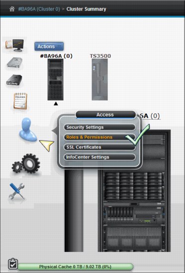
Figure 8-117 TS7700 Virtualization Engine MI Roles & Permissions window
Figure 8-118 shows the Roles & Permissions window, listing the user roles and a summary of each role.

Figure 8-118 Roles & Permissions window
Each role is described in the following list:
•Operator: The operator has access to monitoring information, but is restricted from changing settings for performance, network configuration, feature licenses, user accounts, and custom roles. The operator is also restricted from inserting and deleting logical volumes.
•Lead Operator: The lead operator has access to monitoring information and can perform actions for volume operation. The lead operator has nearly identical permissions to the administrator, but cannot change network configuration, feature licenses, user accounts, and custom roles.
•Administrator: The administrator has the highest level of authority, and can view all windows and perform any action, including the addition and removal of user accounts. The administrator has access to all service functions and TS7700 Virtualization Engine resources.
•Manager: The manager has access to monitoring information, performance data, and functions, and can perform actions for users. The manager is restricted from changing most settings, including those for logical volume management, network configuration, feature licenses, user accounts, and custom roles.
•Custom roles: The administrator can name and define 10 custom roles by selecting the individual tasks that are permitted to each custom role. Tasks can be assigned to a custom role in the Roles and Assigned Permissions window.
Roles and Assigned Permissions table
The Roles and Assigned Permissions table is a dynamic table that displays the complete list of TS7700 Virtualization Engine Grid tasks and the permissions that are assigned to selected user roles.
To view the Roles and Assigned Permissions table, complete the following steps:
1. Select the check box to the left of the role to be displayed. You can select more than one role to display a comparison of permissions.
2. Select Properties from the Select Action menu.
3. Click Go.
The first column of the Roles and Assigned Permissions table lists all the tasks available to users of the TS7700 Virtualization Engine. Subsequent columns show the assigned permissions for selected role (or roles). A check mark denotes permitted tasks for a user role. A null dash (-) denotes prohibited tasks for a user role.
Permissions for predefined user roles cannot be modified. You can name and define up to 10 different custom roles, if necessary. You can modify permissions for custom roles in the Roles and Assigned Permissions table. You can modify only one custom role at a time.
To modify a custom role, complete the following steps:
1. Enter a unique name for the custom role in the Name of Custom Role field.
2. Modify the custom role to fit your requirements by selecting (permitting) or clearing (prohibiting) tasks. Selecting or clearing a parent task affects any child tasks. However, a child task can be selected or cleared independently of a parent task. You can apply the permissions of a predefined role to a custom role by selecting a role from the Role Template menu and clicking Apply. You can then customize the permissions by selecting or clearing tasks.
3. After all tasks for the custom role are selected, click Submit Changes to activate the new custom role.
|
Remember: You can apply the permissions of a predefined role to a custom role by selecting a role from the Role Template menu and clicking Apply. You can then customize the permissions by selecting or clearing tasks.
|
SSL Certificates window
Use the window shown in Figure 8-119 to view, import, or delete SSL certificates that support secure connections to a Storage Authentication Service server from a TS7700 Virtualization Engine Cluster. If a Primary or alternative Server URL, defined by a Storage Authentication Service Policy, uses the HTTPS protocol, a certificate for that address must be defined in this window.

Figure 8-119 SSL Certificates window
The Certificates table displays the following identifying information for SSL certificates on the cluster:
•Alias: A unique name to identify the certificate on the system.
•Issued To: The distinguished name of the entity requesting the certificate.
•Fingerprint: A number that specifies the Secure Hash Algorithm (SHA hash) of the certificate. This number can be used to verify the hash for the certificate at another location, such as the client side of a connection.
•Expiration: The expiration date of the signer certificate for validation purposes.
To import a new SSL certificate, complete the following steps:
1. Select Retrieve from port from the Select Action menu and click Go. The Retrieve from Port window opens.
2. Enter the host and port from which the certificate is retrieved, and a unique value for
the alias.
the alias.
3. Click Retrieve Signer Information. To import the certificate, click OK. To abandon the operation and return to the SSL Certificates window, click Cancel.
To delete an existing SSL certificate, complete the following steps:
1. Select the radio button next to the certificate that you want to delete, select Delete from the Select Action menu, and click Go. The Confirm Delete SSL Certificate window opens and prompts you to confirm your decision to delete the SSL certificate.
2. Click OK to delete the certificate and return to the SSL Certificates window. Click Cancel to abandon the delete operation and return to the SSL Certificates window.
InfoCenter Settings window
Use the window shown in Figure 8-120 to upload a new TS7700 Virtualization Engine IBM Knowledge Center to the cluster’s MI.

Figure 8-120 InfoCenter Settings window
This window has the following items:
•Current Version section, where you can identify or access the following items:
– Identify the version level and date of the IBM Knowledge Center that is installed on
the cluster.
the cluster.
– Access a product database where you can download a JAR file containing a newer version of the IBM Knowledge Center.
– Access an external site displaying the most recently published version of the IBM Knowledge Center.
•The TS7700 IBM Knowledge Center download site link.
Click this link to open the Fix Central product database so that you can download a new version of the TS7700 Virtualization Engine IBM Knowledge Center as a .jar file (if available):
a. Select System Storage from the Product Group menu.
b. Select Tape Systems from the Product Family menu.
c. Select TS7700 Virtualization Engine from the Product menu.
d. Click Continue.
e. On the Select Fixes page, check the box next to the wanted InfoCenter Update file (if available).
f. Click Continue.
g. On the Download Options page, select Download using Download Director.
h. Select the check box next to Include prerequisites and co-requisite fixes.
i. Click Continue.
j. On the Download files using Download Director page, ensure that the check box next to the InfoCenter Update version that you want is checked and click Download now. The Download Director applet opens. The downloaded file is saved at C:DownloadDirector.
•After you receive a new .jar file that contains the updated IBM Knowledge Center (either from the Fix Central database or from an SSR), save the .jar file to a local directory.
To upload and install the new IBM Knowledge Center, complete the following steps:
a. Click Browse to open the File Upload window.
b. Go to the folder that contains the new .jar file.
c. Highlight the new .jar file name and click Open.
d. Click Upload to install the new IBM Knowledge Center on the cluster’s MI.
8.2.10 The Settings icon
The TS7700 Virtualization Engine MI pages collected under the Settings icon can help you view or change cluster network settings, feature licenses, SNMP, and library port access groups.
Cluster network settings
Use this page to set or modify IP addresses for the selected IBM TS7700 Virtualization Engine Cluster.
Figure 8-121 shows the Cluster Network Setting navigation and the Customer IP Addresses tab.

Figure 8-121 Customer IP Addresses tab
Customer IP Addresses tab
Use this tab to set or modify the MI IP addresses for the selected cluster. Each cluster is associated with two routers or switches. Each router or switch is assigned an IP address and one virtual IP address is shared between routers or switches.
|
Note: Any modifications to IP addresses on the accessing cluster interrupt access to that cluster for all current users. If the accessing cluster IP addresses are modified, the current users are redirected to the new virtual address.
|
The following fields show on this tab:
•IPv4: Select this radio button if the cluster can be accessed by an IPv4 address. If this option is disabled, all incoming IPv4 traffic is blocked, although loop-back traffic is still permitted.
If this option is enabled, you must specify the following addresses:
– <Cluster Name> IP address: An AIX virtual IPv4 address that receives traffic on both customer networks. This field cannot be blank if IPv4 is enabled.
– Primary Address: The IPv4 address for the primary customer network. This field cannot be blank if IPv4 is enabled.
– Secondary Address: The IPv4 address for the secondary customer network. This field cannot be blank if IPv4 is enabled.
– Subnet Mask: The IPv4 subnet mask used to determine the addresses present on the local network. This field cannot be blank if IPv4 is enabled.
– Gateway: The IPv4 address used to access systems outside the local network.
A valid IPv4 address is 32 bits long, consists of four decimal numbers, each ranging from 0 - 255, separated by periods, such as 98.104.120.12 for example.
•IPv6: Select this radio button if the cluster can be accessed by an IPv6 address. If this option is disabled, all incoming IPv6 traffic is blocked, although loop-back traffic is still permitted. If you enable this option and do not designate any additional IPv6 information, the minimum required local addresses for each customer network interface will automatically be enabled and configured using neighbor discovery. If this option is enabled, you can specify the following addresses:
– Primary Address: The IPv6 address for the primary network. This field cannot be blank if IPv6 is enabled.
– Secondary Address: The IPv6 address for the secondary network. This field cannot be blank if IPv6 is enabled.
– Prefix Length: The IPv6 prefix length used to determine the addresses present on the local network. The value in this field is an integer 1 - 128. This field cannot be blank if IPv6 is enabled.
– Gateway: The IPv6 address used to access systems outside the local network.
A valid IPv6 address is a 128-bit long hexadecimal value separated into 16-bit fields by colons, such as 3afa:1910:2535:3:110:e8ef:ef41:91cf for example.
Leading zeros can be omitted in each field, so that :0003: can be written as :3:. A double colon (::) can be used once per address to replace multiple fields of zeros, for example:
3afa:0:0:0:200:2535:e8ef:91cf
can be written as:
3afa::200:2535:e8ef:91cf
•DNS Server: The IP addresses of any domain name server (DNS), separated by commas. DNS addresses are only needed if you specify a symbolic domain name rather than a numeric IP address for one or more of the following types of information:
– Primary Server URL on the Add External policy page
– Encryption Key Server address
– SNMP server address
– Security server address
If this field is left blank, the DNS server address is populated by Dynamic Host Configuration Protocol (DHCP).
The address values can be in IPv4 or IPv6 format. A maximum of three DNS servers can be added. Any spaces entered in this field are removed.
To submit changes, click Submit. If your changes apply to the accessing cluster, a warning message is displayed that indicates that the current user access will be interrupted. To accept changes to the accessing cluster, click OK. To reject changes to the accessing cluster and return to the IP Addresses tab, click Cancel.
To reject the changes made to the IP addresses fields and reinstate the last submitted values, select Reset. You can also refresh the page to reinstate the last submitted values for each field.
Encrypt Grid Communication tab
Use this tab to encrypt grid communication between specific clusters.
|
Important: Enabling grid encryption significantly affects the performance of the TS7700 Virtualization Engine. System performance can be reduced by 70% or more when grid encryption is enabled.
|
Figure 8-122 shows the Encrypt Grid Communication tab. In the example, the option was to encrypt grid communications between Cluster 3 and Cluster 5, and also between Cluster 0 and Cluster 3. The remaining paths in the example are not encrypted.
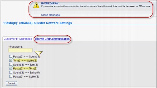
Figure 8-122 Encrypt Grid Communication tab
This tab includes the following fields:
•Password: This password is used as an encryption key to protect grid communication. This value has a 255 ASCII character limit, and is required.
•Cluster communication paths: Select the box next to each cluster communication path to be encrypted.
You can select a communication path between two clusters only if both clusters meet all the following conditions:
•Are online
•Operate at a microcode level of 8.30.0.x or higher
•Operate using IPv6-capable servers (3957-V07/VEB)
To submit changes, click Submit.
Feature licenses
Use this page to view information about feature licenses, or to activate or remove feature licenses from the IBM TS7700 Virtualization Engine Cluster.
Figure 8-123 shows the Feature Licenses page.
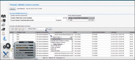
Figure 8-123 Feature Licenses page
The fields on the Feature Licenses page in the MI are described:
Cluster common resources
The Cluster common resources table displays a summary of resources affected by activated features. The following information is displayed:
The Cluster common resources table displays a summary of resources affected by activated features. The following information is displayed:
Cluster-Wide Disk Cache Enabled
The amount of disk cache enabled for the entire cluster, in terabytes (TB). If the selected cluster does not possess a physical library, the value in this field displays the total amount of cache installed on the cluster. Access to cache by a cluster without a physical library is not controlled by feature codes.
The amount of disk cache enabled for the entire cluster, in terabytes (TB). If the selected cluster does not possess a physical library, the value in this field displays the total amount of cache installed on the cluster. Access to cache by a cluster without a physical library is not controlled by feature codes.
Cross-Cluster Communication (Grid)
Whether cross-cluster communication is enabled on the grid. If this option is enabled, multiple clusters can form a grid. The possible values are Enabled and Disabled.
Whether cross-cluster communication is enabled on the grid. If this option is enabled, multiple clusters can form a grid. The possible values are Enabled and Disabled.
Peak data throughput
The Peak data throughput table displays for each vnode the peak data throughput in megabytes per second (MBps). The following information is displayed:
The Peak data throughput table displays for each vnode the peak data throughput in megabytes per second (MBps). The following information is displayed:
Vnode Name of the vnode.
Peak data throughput
The upper limit of the data transfer speed between the vnode and the host, displayed in MBps.
The upper limit of the data transfer speed between the vnode and the host, displayed in MBps.
Currently activated feature licenses
The Currently activated feature licenses table displays a summary of features installed on each cluster:
The Currently activated feature licenses table displays a summary of features installed on each cluster:
Feature Code The feature code number of the installed feature.
Feature Description A description of the feature installed by the feature license.
License Key The 32-character license key for the feature.
Node The name and type of the node on which the feature is installed.
Node Serial Number The serial number of the node on which the feature is installed.
Activated The date and time the feature license was activated.
Expires The expiration status of the feature license. The following values are possible:
Day/Date The day and date on which the feature license is set to expire.
Never The feature is permanently active and never expires.
One-time use The feature can be used once and has not yet been used.
|
Note: You can back up these settings as part of the ts7700_cluster<cluster ID>.xmi file and restore them for later use. When the backup settings are restored, new settings are added but no settings are deleted. You cannot restore feature license settings to a cluster different from the cluster that created the ts7700_cluster<cluster ID>.xmi backup file. After you restore feature license settings on a cluster, it is suggested that you log out and then log in to refresh the system.
|
Use the menu on the Currently activated feature licenses table to activate or remove a feature license. You can also use this menu to sort and filter feature license details.
SNMP
Use this page on the TS7700 Virtualization Engine MI to view or modify the simple network management protocols (SNMP) configured on an IBM TS7700 Virtualization Engine Cluster. Figure 8-124 shows the SNMP page in the MI.

Figure 8-124 SNMP page and options
This page enables you to configure SNMP traps that will log events, such as logins, configuration changes, status changes (vary on, vary off, or service prep), shutdown, and code updates. SNMP is a networking protocol that enables an IBM TS7700 Virtualization Engine to automatically gather and transmit information about alerts and status to other entities in the network.
When adding or modifying SNMP destinations, follow this advice:
•Use IPv4 or IPv6 addresses as destinations rather than a fully qualified domain name (FQDN).
•Verify that any FQDN used correctly addresses its IP address.
Test only one destination at a time when testing SNMP configuration to ensure that FQDN destinations are working properly.
SNMP settings
Use this section to configure global settings that apply to SNMP traps on an entire cluster. The following settings are configurable:
SNMP Version The SNMP version. It defines the protocol used in sending SNMP requests and is determined by the tool you are using to monitor SNMP traps. Different versions of SNMP traps work with different management applications. The following values are possible:
V1 The suggested trap version; compatible with the greatest number of management applications. No alternative version is supported.
Enable SNMP Traps A check box that enables or disables SNMP traps on a cluster. A checked box enables SNMP traps on the cluster; a cleared box disables SNMP traps on the cluster. The check box is cleared, by default.
Trap Community Name
The name that identifies the trap community and is sent along with the trap to the management application. This value behaves as a password; the management application will not process an SNMP trap unless it is associated with the correct community. This value must be 1 - 15 characters in length and composed of Unicode characters. The default value for this field is public.
The name that identifies the trap community and is sent along with the trap to the management application. This value behaves as a password; the management application will not process an SNMP trap unless it is associated with the correct community. This value must be 1 - 15 characters in length and composed of Unicode characters. The default value for this field is public.
Send Test Trap Select this button to send a test SNMP trap to all destinations listed in the Destination Settings table using the current SNMP trap values. The Enable SNMP Traps check box does not need to be checked to send a test trap.
If the SNMP test trap is received successfully and the information is correct, click Submit Changes.
Submit Changes Select this button to submit changes to any of the global settings, including the fields SNMP Version, Enable SNMP Traps, and Trap Community Name.
Destination Settings Use the Destination Settings table to add, modify, or delete a destination for SNMP trap logs. You can add, modify, or delete a maximum of 16 destination settings at one time.
|
Note: A user with read-only permissions cannot modify the contents of the Destination Settings table.
|
The following settings are configurable:
IP Address The IP address of the SNMP server. This value can take any of the following formats: IPv4, IPv6, a host name resolved by the system (such as localhost), or an FQDN if a domain name server (DNS) is provided. A value in this field is required.
|
Tip: A valid IPv4 address is 32 bits long, consists of four decimal numbers, each ranging from 0 - 255, separated by periods, such as 98.104.120.12
A valid IPv6 address is a 128-bit long hexadecimal value separated into 16-bit fields by colons, such as 3afa:1910:2535:3:110:e8ef:ef41:91cf. Leading zeros can be omitted in each field, so that :0003: can be written as :3:. A double colon (::) can be used once per address to replace multiple fields of zeros.
For example, 3afa:0:0:0:200:2535:e8ef:91cf” is also 3afa::200:2535:e8ef:91cf”.
|
Port The port to which the SNMP trap logs are sent. This value must be a number 0 - 65535. A value in this field is required.
Use the Select Action menu on the Destination Settings table to add, modify, or delete an SNMP trap destination. Destinations are changed in the vital product data (VPD) as soon as they are added, modified, or deleted. These updates do not depend on clicking Submit Changes.
|
Note: Any change to SNMP settings is logged on the Tasks page.
|
Library Port Access Groups page
Use this page to view information about library port access groups used by the IBM TS7700 Virtualization Engine. Library port access groups enable you to segment resources and authorization by controlling access to library data ports. Figure 8-125 on page 449 shows the library port access group link.
|
Tip: This page is only visible if at least one instance of FC5271 (Selective device access control (SDAC)) is installed on all clusters in the grid.
|

Figure 8-125 Library Port Access Group link
Access Groups table
The Access Groups table displays information about existing library port access groups. Figure 8-126 shows the Library Port Access Groups page.

Figure 8-126 Library Port Access Groups page
You can use the Access Groups table to create a new library port access group. Also, you can modify or delete an existing access group as shown in Figure 8-127.

Figure 8-127 Add Access group
The following status information is displayed in the Access Groups table:
Name The identifying name of the access group. This name must be unique and cannot be modified after it is created. It must contain 1 - 8 characters, and the first character in this field cannot be a number. Valid characters for this field are A - Z, 0 - 9, $, @, *, #, and %.
The default access group is identified by the name "- - - - - - - - ". This group can be modified but cannot be deleted.
Library Port IDs A list of Library Port IDs accessible using the defined access group. This field contains a maximum of 750 characters, or 31 Library Port IDs separated by commas or spaces. A range of Library Port IDs is signified by using a hyphen (-). This field can be left blank.
The default access group has a value in this field that is 0x01-0xFF. Initially, all port IDs are shown by default. However, after modification, this field can change to show only the IDs corresponding to the existing vnodes.
|
Important: VOLSERs not found in the Selective Device Access Control (SDAC) VOLSER range table use this default group to determine access. You can modify this group to remove any or all default Library Port IDs. However, if all default Library Port ID values are removed, no access is granted to any volumes not in a defined range.
|
Description A description of the access group. This field contains a maximum of 70 characters.
Use the Select Action menu on the Access Groups table to add, modify, or delete a library port access group.
Access Groups Volume Ranges
The Access Groups Volume Ranges table displays VOLSER range information for existing library port access groups. You can also use the Select Action menu on this table to add, modify, or delete a VOLSER range defined by a library port access group.
The Access Groups Volume Ranges table displays VOLSER range information for existing library port access groups. You can also use the Select Action menu on this table to add, modify, or delete a VOLSER range defined by a library port access group.
Start VOLSER The first VOLSER in the range defined by an access group.
End VOLSER The last VOLSER in the range defined by an access group.
Access Group The identifying name of the access group, defined by the Name field in the Access Groups table.
Use the Select Action menu on the Access Group Volume Ranges table to add, modify, or delete a VOLSER range associated with a library port access group.
You can show the inserted volume ranges. To view the current list of virtual volume ranges in the TS7700 Cluster, enter the start and end VOLSERs and click Show.
|
Note: Access groups and access group ranges are backed up and restored together. For additional information, see “Backup settings” on page 460 and “Restore Settings page” on page 463.
|
Cluster settings
Cluster settings can help you view or change settings that determine how a cluster runs copy policy overrides, applies Inhibit Reclaim schedules, uses an encryption key server, implements write protect mode, and runs backup and restore operations.
For an evaluation of different scenarios and examples where those overrides benefit the overall performance, see 4.2, “Planning for a grid operation” on page 139.
Copy Policy Override
Figure 8-128 shows the Cluster Settings window navigating to the Copy Policy Override window.

Figure 8-128 Cluster Settings and Copy Policy Override
Use this page to override local copy and I/O policies for an IBM TS7700 Virtualization Engine Cluster. For the selected cluster, you can tailor copy policies to override certain copy or I/O operations. Select the check box next to one or more of the following settings to specify a policy override:
•Prefer local cache for Fast Ready mount requests
When this setting is selected, a scratch (Fast Ready) mount selects the local TVC in the following conditions:
– The Copy Mode field defined by the Management Class for the mount has a value other than No Copy defined for the local cluster.
– The local cluster is not in a degraded state. The following examples are degraded states:
• Out of cache resources
• Out of physical scratch
|
Note: This override can be enabled independently of the status of the copies in the cluster.
|
•Prefer local cache for non-Fast Ready mount requests
This override causes the local cluster to satisfy the mount request if both of the following conditions are true:
– The cluster is available.
– The local cluster has a valid copy of the data, even if that data is only resident on physical tape.
If the local cluster does not have a valid copy of the data, the default cluster selection criteria applies.
•Force volumes mounted on this cluster to be copied to the local cache
When this setting is selected for a private (non-Fast Ready) mount, a copy operation is performed on the local cluster as part of the mount processing. When this setting is selected for a scratch (Fast Ready) mount, the Copy Consistency Point on the specified Management Class is overridden for the cluster with a value of Rewind Unload. This override does not change the definition of the Management Class, but influences the replication policy.
•Enable fewer RUN consistent copies before reporting RUN command complete
When this setting is selected, the maximum number of Rewind Unload (RUN) copies, including the source, is determined by the value entered at Number of required RUN consistent copies including the source copy. This value must be consistent before the RUN operation completes. If this option is not selected, the Management Class definitions are used explicitly. Therefore, the number of RUN copies can be from one to the number of clusters in the grid configuration or the total number of clusters configured with a RUN Copy Consistency Point.
•Ignore cache preference groups for copy priority
If this option is selected, copy operations ignore the cache preference group when determining the priority of volumes copied to other clusters.
|
Note: These settings override the default TS7700 Virtualization Engine behavior and can be different for every cluster in a grid.
|
Follow these steps to change any of the settings on this page:
1. Select or clear the box next to the setting that you want to change. If you enable Enable fewer RUN consistent copies before reporting RUN command complete, you can alter the value for Number of required RUN consistent copies including the source copy.
2. Click Submit Changes.
Inhibit Reclaim Schedules page
Use this page to add, modify, or delete Inhibit Reclaim schedules used to postpone tape reclamation in an IBM TS7740 or TS7720T Virtualization Engine cluster.
This page is visible but disabled on the TS7700 Virtualization Engine MI if the grid possesses a physical library, but the selected cluster does not. The following message is displayed:
The cluster is not attached to a physical tape library.
|
Tip: This page is not visible on the TS7700 Virtualization Engine MI if the grid does not possess a physical library.
|
Reclamation can improve tape usage by consolidating data on some physical volumes, but it uses system resources and can affect host access performance. The Inhibit Reclaim schedules function can be used to disable reclamation in anticipation of increased host access to physical volumes. Figure 8-129 shows an Inhibit Reclamation Schedules window.

Figure 8-129 Inhibit Reclaim Schedules window
The following fields on this page are described:
Schedules The Schedules table displays the list of Inhibit Reclaim schedules that are defined for each partition of the grid. It displays the day, time, and duration of any scheduled reclamation interruption. All inhibit reclaim dates and times are displayed first in Coordinated Universal Time (Coordinated Universal Time) and then in local time. The status information is displayed in the Schedules table:
Coordinated Universal Time Day of Week
The Coordinated Universal Time day of the week on which the reclamation will be inhibited. The following values are possible:
Every Day Sunday, Monday, Tuesday, Wednesday, Thursday, Friday, or Saturday.
Coordinated Universal Time Start Time
The Coordinated Universal Time time in hours (H) and minutes (M) at which reclamation begins to be inhibited. The values in this field must take the form HH:MM. Possible values for this field include 00:00 through 23:59.
The Start Time field includes a time chooser clock icon. You can enter hours and minutes manually by using 24-hour time designations, or you can use the time chooser to select a start time based on a 12-hour (AM/PM) clock.
Local Day of Week The day of the week in local time on which the reclamation will be inhibited. The day recorded reflects the time zone in which your browser is located. The following values are possible:
Every Day Sunday, Monday, Tuesday, Wednesday, Thursday, Friday, or Saturday.
Local Start Time The local time in hours (H) and minutes (M) at which reclamation begins to be inhibited. The values in this field must take the form HH:MM. The time recorded reflects the time zone in which your browser is located. Possible values for this field include 00:00 through 23:59. The Start Time field includes a time chooser clock icon. You can enter hours and minutes manually using 24-hour time designations, or you can use the time chooser to select a start time based on a 12-hour (AM/PM) clock.
Duration The number of days (D) hours (H) and minutes (M) that the reclamation will be inhibited. The values in this field must take the form: DD days HH hours MM minutes. Possible values for this field include 0 day 0 hour 1 minute through 1 day 0 hour 0 minute if the day of the week is Every Day. Otherwise, possible values for this field are 0 day 0 hour 1 minute through 7 days 0 hour 0 minute.
|
Note: Inhibit Reclaim schedules cannot overlap.
|
Use the menu on the Schedules table to add a new Inhibit Reclaim schedule or to modify or delete an existing schedule. Figure 8-130 shows the Add Inhibit Reclaim Schedule page.
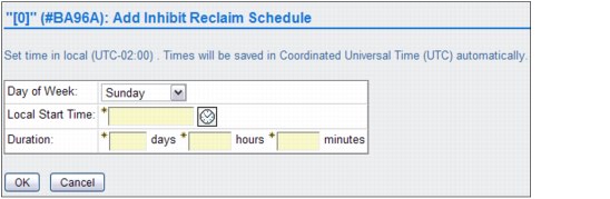
Figure 8-130 Add Inhibit Reclaim Schedule window
To modify an Inhibit Reclaim schedule, follow these steps:
1. From the Inhibit Reclaim Schedules page, go to the Schedules table.
2. Select the radio button next to the Inhibit Reclaim schedule to be modified.
3. Select Modify from the Select Action menu.
4. Click Go to open the Modify Inhibit Reclaim Schedule page.
The values are the same as for the Add Inhibit Reclaim Schedule, listed in Figure 8-130.
To delete an Inhibit Reclaim schedule, follow these steps:
1. From the Inhibit Reclaim Schedules page, go to the Schedules table.
2. Select the radio button next to the Inhibit Reclaim schedule that you want to delete.
3. Select Delete from the Select Action menu.
4. Click Go to open the Confirm Delete Inhibit Reclaim Schedule window.
5. Click OK to delete the Inhibit Reclaim schedule and return to the Inhibit Reclaim Schedules page, or click Cancel to abandon the delete operation and return to the Inhibit Reclaim Schedules page.
|
Note: Plan the Inhibit Reclaim schedules carefully. Running the reclaims during peak times can affect your production, and not having enough reclaim schedules influences your media consumption.
|
Encryption Key Server Addresses page
Use this page for setting the Encryption Key Server addresses in the IBM TS7700 Virtualization Engine. To watch a tutorial that shows the properties of the encryption key server, click the View tutorial link in the MI page. Figure 8-131 shows the Encryption Key Server Addresses setup window.
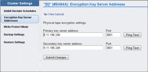
Figure 8-131 Encryption Key Server Addresses page
This page is visible but disabled on the TS7700 Virtualization Engine MI if the grid possesses a physical library, but the selected cluster does not. The following message is displayed:
The cluster is not attached to a physical tape library.
|
Tip: This page is not visible on the TS7700 Virtualization Engine MI if the grid does not possess a physical library.
|
The Encryption Key Server assists encryption-enabled tape drives in generating, protecting, storing, and maintaining encryption keys that are used to encrypt information being written to and to decrypt information being read from tape media (tape and cartridge formats).
|
Note: Your Encryption Key Server software must support default keys to use this option.
|
The following settings are used to configure the IBM TS7700 Virtualization Engine connection to an encryption key server.
|
Tip: You can back up these settings as part of the ts7700_cluster<cluster ID>.xmi file and restore them for later use or use with another cluster. If a key server address is empty at the time that the backup is run, when it is restored, the port settings are the same as the default values.
|
The following list describes the settings:
•Primary key server address
The key server name or IP address that is primarily used to access the encryption key server. This address can be a fully qualified host name or an IP address in IPv4 or IPv6 format. This field is not required if you do not want to connect to an encryption key server.
|
Tip: A valid IPv4 address is 32 bits long, consists of four decimal numbers, each
0 - 255, separated by periods, such as 98.104.120.12. A valid IPv6 address is a 128-bit long hexadecimal value separated into 16-bit fields by colons, such as 3afa:1910:2535:3:110:e8ef:ef41:91cf. Leading zeros can be omitted in each field, so that :0003: can be written as :3:. A double colon (::) can be used once per address to replace multiple fields of zeros. For example, 3afa:0:0:0:200:2535:e8ef:91cf can be written as: 3afa::200:2535:e8ef:91cf.
|
A fully qualified host name is a domain name that uniquely and absolutely names a computer. It consists of the host name and the domain name. The domain name is one or more domain labels that place the computer in the DNS naming hierarchy. The host name and the domain name labels are separated by periods and the total length of the host name cannot exceed 255 characters.
•Primary key server port
The port number of the primary key server. Valid values are any whole number 0 - 65535; the default value is 3801. This field is only required if a primary key address is used.
•Secondary key server address
The key server name or IP address that is used to access the Encryption Key Server when the primary key server is unavailable. This address can be a fully qualified host name or an IP address in IPv4 or IPv6 format. This field is not required if you do not want to connect to an encryption key server. See the primary key server address description for IPv4, IPv6, and fully qualified host name value parameters.
•Secondary key server port
The port number of the secondary key server. Valid values are any whole number
0 - 65535; the default value is 3801. This field is only required if a secondary key address is used.
0 - 65535; the default value is 3801. This field is only required if a secondary key address is used.
•Using the Ping Test
Use the Ping Test buttons to check the cluster network connection to a key server after changing a cluster’s address or port. If you change a key server address or port and do not submit the change before using the Ping Test button, you receive the following message:
to perform a ping test you must first submit your address and/or port changes.
After the ping test has been started, one of the following two messages will occur:
– T he ping test against the address “<address>” on port “<port>” was successful.
– The ping test against the address “<address>” on port “<port>” from “<cluster>” has failed. The error returned was: <error text>.
Click Submit Changes to save changes to any of these settings.
Write Protect Mode page
Use this page to view Write Protect Mode settings in an IBM TS7700 Virtualization Engine Cluster. With R3.1 Licensed Internal Code, this page also is displayed if the Write Protect Mode is enabled due to a Flash Copy, showing in the Current State field: Write protect for Flash Copy enabled.
|
Note: Flash Copy is enabled from LI REQ (Library Request Host Console) command.
|
With Flash Copy in progress, no modifications are allowed on the Write Protect Mode page until the Flash Copy testing is completed. When Write Protect Mode is enabled on a cluster, host commands fail if they are sent to virtual devices in that cluster and attempt to modify a volume’s data or attributes.
Meanwhile, host commands sent to virtual devices in peer clusters are allowed to continue with full read and write access to all volumes in the library. Write Protect Mode is used primarily for client-initiated disaster recovery testing. In this scenario, a recovery host connected to a non-production cluster must access and validate production data without any risk of modifying it.
A cluster can be placed into Write Protect Mode only if the cluster is online. After the mode is set, the mode is retained through intentional and unintentional outages and can only be disabled through the same MI window used to enable the function. When a cluster within a grid configuration has Write Protect Mode enabled, standard grid functions, such as virtual volume replication and virtual volume ownership transfer, are unaffected.
Virtual volume categories can be excluded from Write Protect Mode. Starting with R3.1 of Licensed Internal Code, up to 32 categories can be identified and set to include or exclude from Write Protect Mode using the Category Write Protect Properties table. Additionally, write-protected volumes in any scratch (Fast Ready) category can be mounted as private volumes if the Ignore Fast Ready characteristics of write-protected categories check box is selected. Figure 8-132 shows the Write Protect Mode page.

Figure 8-132 Write Protect Mode page
The page shown in Figure 8-132 on page 458 has the following information:
Current State The status of Write Protect Mode on the active cluster. The following values are possible:
Disabled Write Protect Mode is disabled on the cluster. No Write Protect settings are in effect for the cluster.
Enabled Write Protect Mode is enabled on the cluster. Any attempt by an attached host to modify a volume or its attributes fails, subject to any defined category exclusions.
Disable Write Protect Mode
Select this radio button to disable Write Protect Mode on the active cluster. If you select this option, no volumes on the cluster are write-protected; all Write Protect settings are disabled.
Select this radio button to disable Write Protect Mode on the active cluster. If you select this option, no volumes on the cluster are write-protected; all Write Protect settings are disabled.
Enable Write Protect Mode
Select this radio button to enable Write Protect Mode on the active cluster. This option prevents hosts attached to this cluster from modifying volumes or their attributes.
Select this radio button to enable Write Protect Mode on the active cluster. This option prevents hosts attached to this cluster from modifying volumes or their attributes.
Ignore Fast Ready characteristics of write protected categories
If this check box is selected, write-protected volumes that have been returned to a scratch or a Fast Ready category continue to be viewed as private volumes. This enables a disaster recovery test host to mount production volumes as private volumes even though the production environment has since returned them to scratch. Peer clusters, such as production clusters, continue to view these volumes as scratch volumes. This setting does not override the scratch (Fast Ready) characteristics of the excluded categories.
If this check box is selected, write-protected volumes that have been returned to a scratch or a Fast Ready category continue to be viewed as private volumes. This enables a disaster recovery test host to mount production volumes as private volumes even though the production environment has since returned them to scratch. Peer clusters, such as production clusters, continue to view these volumes as scratch volumes. This setting does not override the scratch (Fast Ready) characteristics of the excluded categories.
Category Write Protect Properties
Use the Category Write Protect Properties table to add, modify, or delete categories to be selectively excluded from Write Protect Mode. Disaster recovery test hosts or locally connected production partitions can continue to read and write to local volumes if their volume categories are excluded from write protect. These hosts must use a set of categories different from those primary production categories that are write protected.
Use the Category Write Protect Properties table to add, modify, or delete categories to be selectively excluded from Write Protect Mode. Disaster recovery test hosts or locally connected production partitions can continue to read and write to local volumes if their volume categories are excluded from write protect. These hosts must use a set of categories different from those primary production categories that are write protected.
When Write Protect Mode is enabled, any categories added to this table must display a value of Yes in the Excluded from Write Protect field before the volumes in that category can be modified by an accessing host. Figure 8-133 shows the Add Category window.

Figure 8-133 Add Category window
The following category fields are displayed in the Category Write Protect Properties table:
•Category Number: The identifier for a defined category. This is an alphanumeric hexadecimal value between 0x0001 and 0xFEFF (0x0000 and 0xFFxx cannot be used). Values entered do not include the 0x prefix, although this prefix is displayed on the Cluster Summary page. Values entered are padded up to four places. Letters used in the category value must be capitalized.
•Excluded from Write Protect: Whether the category is excluded from Write Protect Mode. The following values are possible:
– Yes: The category is excluded from Write Protect Mode. When Write Protect is enabled, volumes in this category can be modified when accessed by a host.
– No: The category is not excluded from Write Protect Mode. When Write Protect is enabled, volumes in this category cannot be modified when accessed by a host.
•Description: A descriptive definition of the category and its purpose. This description must contain 0 - 63 Unicode characters.
Use the menu on the Category Write Protect Properties table to add a category, or modify or delete an existing category.
You must click Submit Changes to save any changes made to the Write Protect Mode settings.
Backup settings
Use this page to back up the settings from an IBM TS7700 Virtualization Engine Cluster. Figure 8-134 shows an example of Backup Settings page.

Figure 8-134 Backup Settings page
|
Important: Backup and restore functions are not supported between clusters operating at different code levels. Only clusters operating at the same code level as the accessing cluster (the one addressed by the web browser) can be selected for Backup or Restore. Clusters operating different code levels are visible, but options are disabled.
|
The Backup Settings table lists the cluster settings that are available for backup:
•Categories: Select this check box to back up scratch (Fast Ready) categories used to group virtual volumes.
•Physical Volume Pools: Select this check box to back up physical volume pool definitions.
|
Note: If the cluster does not possess a physical library, physical volume pools are not available.
|
•All Constructs: Select this check box to select all of the following constructs for backup. Alternatively, you can select a specific construct by checking the box for the one you want:
– Storage Groups: Select this check box to back up defined Storage Groups.
– Management Classes: Select this check box to back up defined Management Classes.
– Storage Classes: Select this check box to back up defined storage classes.
– Data Classes: Select this check box to back up defined Data Classes.
•Inhibit Reclaim Schedule: Select this check box to back up the Inhibit Reclaim schedules used to postpone tape reclamation.
|
Note: If the cluster does not possess a physical library, the Inhibit Reclaim Schedules option is not available.
|
•Library Port Access Groups: Select this check box to back up defined library port access groups.
|
Note: This setting is only available if all clusters in the grid are operating with microcode levels of 8.20.0.xx or higher and the SDAC feature is installed.
|
Library port access groups and access group ranges are backed up and restored together.
•Physical Volume Ranges: Select this check box to back up defined physical volume ranges. If the cluster does not possess a physical library, physical volume ranges are
not available.
not available.
•Security Settings: Select this check box to back up defined security settings:
– Session Timeout
– Account Expiration
– Account Lock
– Encryption Key Server Addresses
– Primary key server address
– Primary key server port
– Secondary key server address
– Secondary key server port
•Cluster Network Settings: Select this box to back up the defined cluster network settings.
•Roles & Permissions: Select this check box to back up defined custom user roles.
|
Important: A restore operation after a backup of cluster settings does not restore or otherwise modify any user, role, or password settings defined by a security policy.
|
•Feature Licenses: Select this check box to back up the settings for currently activated feature licenses.
|
Note: You can back up these settings as part of the ts7700_cluster<cluster ID>.xmi file and restore them for later use on the same cluster. However, you cannot restore feature license settings to a cluster different from the cluster that created the ts7700_cluster<cluster ID>.xmi backup file.
|
The following feature license information is available for backup:
Feature Code The feature code number of the installed feature.
Feature Description A description of the feature installed by the feature license.
License Key The 32-character license key for the feature.
Node The name and type of the node on which the feature is installed.
Node Serial Number The serial number of the node on which the feature is installed.
Activated The date and time the feature license was activated.
Expires The expiration status of the feature license. The following values are possible:
Day/Date The day and date on which the feature license is set to expire.
Never The feature is permanently active and never expires.
One-time use The feature can be used once and has not yet been used.
•Encryption Key Server Addresses: Select this check box to back up defined Encryption Key Server addresses:
– Primary key server address
– Primary key server port
– Secondary key server address
– Secondary key server port
|
Important: A restore operation after a backup of cluster settings does not restore or otherwise modify any user, role, or password settings defined by a security policy.
|
•Copy Policy Override: Select this check box to back up the settings to override local copy and I/O policies.
•SNMP: Select this check box to back up the settings for simple network management protocols (SNMP).
•Write Protect Mode Categories: Select this check box to back up the settings for write protect mode categories.
To back up cluster settings, click a check box next to any of the previous settings and then click Download. A window opens to show that the backup is in progress.
|
Important: If you navigate away from this page while the backup is in progress, the backup operation is stopped and the operation must be restarted.
|
When the backup operation is complete, the backup file ts7700_cluster<cluster ID>.xmi is created. This file is an XML Meta Interchange file. You are prompted to open the backup file or save it to a directory. Save the file. When prompted to open or save the file to a directory, it is suggested that you save the file without changing the .xmi file extension or the file contents.
Any changes to the file contents or extension can cause the restore operation to fail. You can modify the file name before saving it if you want to retain this backup file after subsequent backup operations. If you choose to open the file, it is suggested that you not use Microsoft Excel to view or save it. Microsoft Excel changes the encoding of an XML Meta Interchange file, and the changed file is corrupted when used during a restore operation.
The following settings are not available for backup or recovery:
•User accounts
•Security policies
•Grid identification policies
•Cluster identification policies
•Grid communication encryption (IPSec)
•SSL certificates
Record these settings in a safe place and recover them manually if necessary.
Restore Settings page
Use this page to restore the settings from an IBM TS7700 Virtualization Engine Cluster to a recovered or new cluster.
|
Restriction: Backup and restore functions are not supported between clusters operating at different code levels. Only clusters operating at the same code level as the current cluster can be selected from the Current Cluster Selected graphic. Clusters operating at different code levels are visible, but not available, in the graphic.
|
Figure 8-135 shows the Restore Settings window.

Figure 8-135 Restore Settings window
Follow these steps to restore cluster settings:
1. On the Restore Settings page, click Browse to open the File Upload window.
2. Go to the backup file used to restore the cluster settings. This file has an .xmi extension.
3. Add the file name to the File name field.
4. Click Open or press Enter from your keyboard.
5. Click Show file to review the cluster settings contained in the backup file.
The backup file can contain any of the following settings, but only those settings defined by the backup file are shown:
•Categories : Select this check box to restore scratch (Fast Ready) categories used to group virtual volumes.
•Physical Volume Pools: Select this check box to restore physical volume pool definitions.
|
Important: If the backup file was created by a cluster that did not possess a physical library, physical volume pool settings are reset to default.
|
•All Constructs: Select this check box to restore all of the displayed constructs.
•Storage Groups: Select this check box to restore defined Storage Groups.
•Management Classes: Select this check box to restore defined Management Classes.
Management Class settings are related to the number and order of clusters in a grid. Take special care when restoring this setting. If a Management Class is restored to a grid having more clusters than the grid had when the backup was run, the copy policy for the new cluster or clusters are set as No Copy.
If a Management Class is restored to a grid having fewer clusters than the grid had when the backup was run, the copy policy for the now-nonexistent clusters is changed to No Copy. The copy policy for the first cluster is changed to RUN to ensure that one copy exists in the cluster.
If cluster IDs in the grid differ from cluster IDs present in the restore file, Management Class copy policies on the cluster are overwritten with those from the restore file. Management Class copy policies can be modified after the restore operation completes.
If the backup file was created by a cluster that did not define one or more scratch mount candidates, the default scratch mount process is restored. The default scratch mount process is a random selection routine that includes all available clusters. Management Class scratch mount settings can be modified after the restore operation completes.
•Storage Classes: Select this check box to restore defined storage classes.
•Data Classes: Select this check box to restore defined Data Classes.
If this setting is selected and the cluster does not support logical Write Once Read Many (LWORM), the Logical WORM setting is disabled for all Data Classes on the cluster.
•Inhibit Reclaim Schedule: Select this check box to restore Inhibit Reclaim schedules used to postpone tape reclamation.
A current Inhibit Reclaim schedule is not overwritten by older settings. An earlier Inhibit Reclaim schedule is not restored if it conflicts with an Inhibit Reclaim schedule that currently exists.
|
Note: If the backup file was created by a cluster that did not possess a physical library, the Inhibit Reclaim schedules settings are reset to default.
|
•Library Port Access Groups: Select this check box to restore defined library port access groups.
This setting is only available if all clusters in the grid are operating with microcode levels of 8.20.0.xx or higher.
Library port access groups and access group ranges are backed up and restored together.
•Physical Volume Ranges: Select this check box to restore defined physical volume ranges.
If the backup file was created by a cluster that did not possess a physical library, physical volume range settings are reset to default.
•Roles & Permissions: Select this check box to restore defined custom user roles.
A restore operation after a backup of cluster settings does not restore or otherwise modify any user, role, or password settings defined by a security policy.
•Security Settings: Select this check box to restore defined security settings, for example:
– Session Timeout
– Account Expiration
– Account Lock
•Encryption Key Server Addresses: Select this check box to restore defined Encryption Key Server addresses. If a key server address is empty at the time that the backup is performed, when restored, the port settings are the same as the default values. The following Encryption Key Server address settings can be restored:
– Primary key server address: The key server name or IP address that is primarily used to access the encryption key server.
– Primary key server port: The port number of the primary key server.
– Secondary key server address: The key server name or IP address that is used to access the Encryption Key Server when the primary key server is unavailable.
– Secondary key server port: The port number of the secondary key server.
•Cluster Network Settings: Select this check box to restore the defined cluster network settings.
|
Important: Changes to network settings affect access to the TS7700 MI. When these settings are restored, routers that access the TS7700 MI are reset. No TS7700 grid communications or jobs are affected, but any current users are required to log back on to the TS7700 MI using the new IP address.
|
•Feature Licenses: Select this check box to restore the settings for currently activated feature licenses. When the backup settings are restored, new settings are added but no settings are deleted. After you restore feature license settings on a cluster, it is suggested that you log out and then log in to refresh the system.
|
Note: You cannot restore feature license settings to a cluster different from the cluster that created the ts7700_cluster<cluster ID>.xmi backup file.
|
The following feature license information is available for backup:
Feature Code The feature code number of the installed feature.
Feature Description A description of the feature installed by the feature license.
License Key The 32-character license key for the feature.
Node The name and type of the node on which the feature is installed.
Node Serial Number The serial number of the node on which the feature is installed.
Activated The date and time the feature license was activated.
Expires The expiration status of the feature license. The following values are possible:
Day/Date The day and date on which the feature license is set to expire.
Never The feature is permanently active and never expires.
One-time use The feature can be used once and has not yet been used.
After selecting Show File, the name of the cluster from which the backup file was created is displayed at the top of the page, along with the date and time that the backup occurred.
Select the box next to each setting to be restored. Click Restore.
|
Note: The restore operation overwrites existing settings on the cluster.
|
A warning page opens and asks you to confirm your decision to restore settings. Click OK to restore settings or Cancel to cancel the restore operation.
The Confirm Restore Settings page opens.
|
Important: If you navigate away from this page while the restore is in progress, the restore operation is stopped and the operation must be restarted.
|
The restore cluster settings operation can take 5 minutes or longer. During this step, the MI is communicating the commands to update settings. If you navigate away from this page, the restore settings operation is canceled.
Copy Export Settings window
Use this page to change the maximum number of physical volumes that can be exported by the IBM TS7700 Virtualization Engine. Figure 8-136 shows the Copy Export Settings window.

Figure 8-136 Copy Export Settings window
The Number of physical volumes to export is the maximum number of physical volumes that can be exported. This value is an integer 1 - 10,000. The default value is 2000. To change the number of physical volumes to export, enter an integer in the described field and click Submit.
|
Note: You can modify this field even if a Copy Export operation is running, but the changed value will not take effect until the next Copy Export operation starts.
|
8.2.11 The Service icon
The following topics present information about running service operations and troubleshooting problems for the TS7700 Virtualization Engine. Figure 8-137 shows the Service icon options for a stand-alone TS7720T cluster compared to a grid of TS7720 clusters.
Ownership Takeover Mode only shows when cluster is member of a grid, while Copy Export Recover and Copy Export Recovery Status options appear for a single TS7740 or TS7720T configuration (which are connected to a physical library).
|
Note: Copy Export Recover or Copy Export Recover Status are only available in a single cluster configuration for TS7740 or TS7720T.
|

Figure 8-137 Service Icon options
Use the window shown in Figure 8-138 to enable or disable Ownership Takeover Mode for a failed cluster in a TS7700 Virtualization Engine. The Ownership Takeover Mode must be started from any surviving cluster in the grid when a cluster becomes inaccessible. You do not enable Ownership Takeover Mode from within the failed cluster.
|
Note: Have the Management Interface IP addresses for all clusters in the configuration available for use so that if one cluster fails you can still access the MI.
|

Figure 8-138 MI window to set the Ownership Takeover Mode
When a cluster enters a failed state, enabling Ownership Takeover Mode enables other clusters in the grid to obtain ownership of logical volumes that are owned by the failed cluster. Normally, ownership is transferred from one cluster to another through communication between the clusters. When a cluster fails or the communication links between clusters fail, the normal means of transferring ownership is not available.
Enabling a read/write or read-only takeover mode should not be done if only the communication path between the clusters has failed, and the isolated cluster remains operational. A takeover decision should only be made for a cluster that is indeed no longer operational. The integrity of logical volumes in the grid can be compromised if a takeover mode is enabled for a cluster that is only isolated from the grid (not failed), and there is active host access to it.
Autonomic Ownership Takeover Manager (AOTM), if available and configured, tries to determine if the cluster is alive or failed, enabling the ownership takeover only in case the unresponsive cluster has indeed failed. If the cluster is still alive, AOTM does not initiate a takeover, and the decision is up to the human operator.
If one or more clusters become isolated from one or more peers, those volumes owned by the inaccessible peers cannot be mounted without first enabling an ownership takeover mode. Volumes owned by one of the accessible clusters can be successfully mounted and modified. For those mounts that cannot obtain ownership from the inaccessible peers, the operation fails. In z/OS, the failure for this error code is not permanent, which makes it possible for you to enable ownership takeover and retry the operation.
When Read Only takeover mode is enabled, those volumes requiring takeover are read-only, and fail any operation that attempts to modify the volume attributes or data. Read/write takeover enables full read/write access of attributes and data. If an ownership takeover mode must be enabled when only a WAN/LAN failure is present, read/write takeover should not be used, because it can compromise the integrity of the volumes that are accessed by both isolated groups of clusters.
Read-only takeover mode should be used instead. If full read/write access is required, one of the isolated groups should be taken offline to prevent any use case where both groups attempt to modify the same volume. Figure 8-139 shows the Ownership Takeover Mode window when navigating from the window that is shown in Figure 8-138 on page 469.

Figure 8-139 Ownership Takeover Mode
Figure 8-139 on page 470 shows the local cluster summary, the list of available clusters in the grid, the connection state between local (accessing) cluster and its peers. It also shows the current takeover state for the peer clusters (if enabled or disabled by the accessing cluster) and the current takeover mode.
The Configure AOTM button can be used to configure the values that are displayed in the previous Autonomic Ownership Takeover Mode Configuration table.
|
Important: An IBM SSR must configure the TSSC IP addresses for each cluster in the grid before AOTM can be enabled and configured for any cluster in the grid.
|
Table 8-12 compares the operation of read/write and read-only ownership takeover modes
Table 8-12 Comparing read/write and read-only ownership takeover modes
|
Read/write ownership takeover mode
|
Read-only ownership takeover mode
|
||
|
Operational clusters in the grid can run these tasks:
•Perform read and write operations on the virtual volumes owned by the failed cluster.
•Change virtual volumes owned by the failed cluster to private or SCRATCH status.
|
Operational clusters in the grid can run these tasks:
•Perform read operations on the virtual volumes owned by the failed cluster.
Operational clusters in the grid cannot run these tasks:
•Change the status of a volume to private or scratch.
•Perform read and write operations on the virtual volumes owned by the failed cluster.
|
||
|
A consistent copy of the virtual volume must be available on the grid or the virtual volume must exist in a scratch category. If no cluster failure occurred (grid links down) and the ownership takeover was started by mistake, the possibility exists for two sites to write data to the same virtual volume.
|
If no cluster failure occurred, it is possible that a virtual volume accessed by another cluster in read-only takeover mode contains older data than the one on the owning cluster. This situation can occur if the virtual volume was modified on the owning cluster while the communication path between the clusters was down. When the links are reestablished, those volumes are marked in error.
|
See the TS7700 IBM Knowledge Center available locally by clicking the question mark icon on the upper right corner of the MI page, or online on the following website:
Repair Virtual Volumes page
Use this page to repair virtual volumes in the damaged category for the IBM TS7700 Virtualization Engine Grid. Figure 8-140 shows the Repair Virtual Volumes window of the TS7700 MI.

Figure 8-140 Repair Virtual Volumes window
You can print the table data by clicking Print report, which is shown in Figure 8-140. A comma-separated value (.csv) file of the table data can be downloaded by clicking Download spreadsheet. The following information is displayed on this window:
Repair policy The Repair policy section defines the repair policy criteria for damaged virtual volumes in a cluster. The following criteria is shown:
Cluster’s version to keep
The selected cluster obtains ownership of the virtual volume when the repair is complete. This version of the virtual volume is the basis for repair if the Move to insert category keeping all data option is selected.
The selected cluster obtains ownership of the virtual volume when the repair is complete. This version of the virtual volume is the basis for repair if the Move to insert category keeping all data option is selected.
Move to insert category keeping all data
This option is used if the data on the virtual volume is intact and still relevant. If data has been lost, do not use this option. If the cluster chosen in the repair policy has no data for the virtual volume to be repaired, choosing this option is the same as choosing Move to insert category deleting all data.
This option is used if the data on the virtual volume is intact and still relevant. If data has been lost, do not use this option. If the cluster chosen in the repair policy has no data for the virtual volume to be repaired, choosing this option is the same as choosing Move to insert category deleting all data.
Move to insert category deleting all data
The repaired virtual volumes are moved to the insert category and all data is erased. Use this option if the volume has been returned to scratch or if data loss has rendered the volume obsolete. If the volume has been returned to scratch, the data on the volume is no longer needed. If data loss has occurred on the volume, data integrity issues can occur if the data on the volume is not erased.
The repaired virtual volumes are moved to the insert category and all data is erased. Use this option if the volume has been returned to scratch or if data loss has rendered the volume obsolete. If the volume has been returned to scratch, the data on the volume is no longer needed. If data loss has occurred on the volume, data integrity issues can occur if the data on the volume is not erased.
Damaged Virtual Volumes
The Damaged Virtual Volumes table displays all the damaged virtual volumes in a grid. The following information is shown:
The Damaged Virtual Volumes table displays all the damaged virtual volumes in a grid. The following information is shown:
Virtual Volume The VOLSER of the damaged virtual volume. This field is also a hyperlink that opens the Damaged Virtual Volumes Details page, where more information is available.
Damaged virtual volumes cannot be accessed; repair all damaged virtual volumes that appear on this table. You can repair up to 10 virtual volumes at a time.
Follow these steps to repair damaged virtual volumes:
1. Define the repair policy criteria in the Repair policy section.
2. Select a cluster name from the Cluster’s version to keep menu.
3. Click the radio button next to either Move to insert category keeping all data or Move to insert category deleting all data.
4. In the Damaged Virtual Volumes table, select the check box next to one or more (up to 10) damaged virtual volumes to be repaired by using the repair policy criteria.
5. Select Repair from the Select Action menu.
6. A confirmation message appears at the top of the page to confirm the repair operation. Click View Task History to open the Tasks page to monitor the repair progress. Click Close Message to close the confirmation message.
Network Diagnostics window
The Network Diagnostics window can be used to initiate ping or trace route commands to any IP address or host name from this IBM TS7700 Virtualization Engine cluster. You can use these commands to test the efficiency of grid links and the network system.
Figure 8-141 shows the navigation to the Network Diagnostics window and a ping test example.
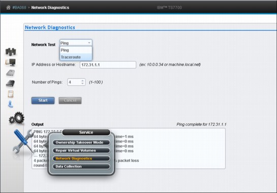
Figure 8-141 Network Diagnostics window
The following information is shown on this window:
•Network Test: The type of test to be run from the accessing cluster. The following values are available:
– Ping: Select this option to initiate a ping test against the IP address or host name entered in the IP Address/Hostname field. This option tests the length of time required for a packet of data to travel from your computer to a specified host, and back again. This option can test whether a connection to the target IP address or host name is enabled, the speed of the connection, and the distance to the target.
– Traceroute: Select this option to initiate a trace route test against the IP address or host name entered in the IP Address/Hostname field. This option traces the path that a packet follows from the accessing cluster to a target address and displays the number of times packets are rebroadcasted by other servers before reaching their destination.
|
Important: The Traceroute command is intended for network testing, measurement, and management. It imposes a heavy load on the network and should not be used during normal operations.
|
– IP Address/Hostname: The target IP address or host name for the selected network test. The value in this field can be an IP address in IPv4 or IPv6 format or a fully qualified host name.
– Number of Pings: Use this field to select the number of pings sent by the Ping command. The range of available pings is 1 - 100. The default value is 4. This field is only displayed if the value in the Network Test field is Ping.
•Start: Click this button to begin the selected network test. This button is disabled if required information is not yet entered on the page or if the network test is in progress.
•Cancel: Click this button to cancel a network test in progress. This button is disabled unless a network test is in progress.
•Output: This field displays the progress output resulting from the network test command. Information that is retrieved by the web interface is displayed in this field as it is received. You can scroll within this field to view output that exceeds the space provided.
The status of the network command is displayed in line with the Output field label and right-aligned over the Output field. The format for the information displayed is shown:
Pinging 98.104.120.12...
Ping complete for 98.104.120.12
Tracing route to 98.104.120.12...
Trace complete to 98.104.120.12
Data Collection window
Use this page to collect a snapshot of data or a detailed log to help check system performance or troubleshoot a problem during the operation of the IBM TS7700 Virtualization Engine.
If you are experiencing a performance issue on a TS7700 Virtualization Engine, you have two options to collect system data for later troubleshooting. The first option, System Snapshot, collects a summary of system data that includes the performance state. This option is useful for intermittently checking the system performance. This file is built in approximately 5 minutes.
The second option, TS7700 Log Collection, enables you to collect historical system information for a time period up to the past 12 hours. This option is useful for collecting data during or soon after experiencing a problem. Based on the number of specified hours, this file can become very large and require over an hour to build.
Figure 8-142 shows the Data Collection page in the MI.

Figure 8-142 Data Collection window
The following information is shown on the Data Collection window:
System Snapshot Check this box to collect a summary of system health and performance from the preceding 15-minute period. You can collect and store up to 24 System Snapshot files at the same time.
TS7700 Log Collection
Check this box to collect and package all logs from the time period designated by the value in the Hours of Logs field. You can collect and store up to two TS7700 Log Collection files at the same time.
Check this box to collect and package all logs from the time period designated by the value in the Hours of Logs field. You can collect and store up to two TS7700 Log Collection files at the same time.
Hours of Logs Use this menu to select the number of preceding hours from which system logs are collected. Possible values are 1 - 12, with a default of 2 hours. The time stamp next to the hours field displays the earliest time from which logs are collected. This time stamp is automatically calculated based on the number displayed in the hours field.
|
Note: Time periods covered by TS7700 Log Collection files cannot overlap. If you attempt to generate a log file that includes a time period covered by an existing log file, a message prompts you to select a different value for the hours field.
|
Continue Click this button to initiate the data collection operation. This operation cannot be canceled after the data collection begins.
|
Note: Data collected during this operation is not automatically forwarded to IBM. You must contact IBM and open a problem management report (PMR) to manually move the collected data off the system.
|
When data collection is started, a message is displayed that contains a button linking to the Tasks window. You can click this button to view the progress of data collection.
|
Important: If you start data collection on a cluster in service mode, you might not be able to check the progress of data collection. Tasks page is not available for clusters in service mode, so there is no link to it in message.
|
Data Collection Limit Reached
This dialog box opens if the maximum number of System Snapshot or TS7700 Log Collection files already exists. You can save a maximum number of 24 System Snapshot files or 2 TS7700 Log Collection files. If you attempt to save more than the maximum of either type, you are prompted to delete the oldest existing version before you continue. The name of any file to be deleted is displayed.
This dialog box opens if the maximum number of System Snapshot or TS7700 Log Collection files already exists. You can save a maximum number of 24 System Snapshot files or 2 TS7700 Log Collection files. If you attempt to save more than the maximum of either type, you are prompted to delete the oldest existing version before you continue. The name of any file to be deleted is displayed.
Click Continue to delete the oldest files and proceed. Click Cancel to abandon the data collection operation.
Problem Description
Optional: Enter a detailed description of the conditions or problem you experienced before you initiated the data collection in this field. Include symptoms and any information that can assist IBM Support in the analysis process, including the description of the preceding operation, VOLSER ID, device ID, any host error codes, any preceding messages or events, time and time zone of incident, and any PMR number (if available). The number of characters in this description cannot
exceed 1000.
Copy Export Recovery window
Use this page to test a Copy Export recovery, or to run an actual Copy Export recovery on the IBM TS7700 Virtualization Engine.
|
Tip: This page is only visible in a single TS7740 or TS7720T configuration (both of which are connected to a physical tape library).
|
Figure 8-143 shows the Copy Export Recovery window.

Figure 8-143 Copy Export recovery window
Copy Export enables the export of all virtual volumes and the virtual volume database to physical volumes, which can then be ejected and saved as part of a data retention policy for disaster recovery. You can also use this function to test system recovery.
See Chapter 11, “Copy Export” on page 697 for a detailed explanation of the Copy Export function.
Before you attempt a Copy Export, ensure that all physical media to be used in the recovery is inserted. During a Copy Export recovery, all current virtual and physical volumes are erased from the database and virtual volumes are erased from the cache. Do not attempt a Copy Export operation on a cluster where current data is to be saved.
|
Important: In a grid configuration, each TS7700 Virtualization Engine is considered a separate source. Therefore, only the physical volume that is exported from a source TS7700 Virtualization Engine can be used for the recovery of that source. Physical volumes exported from more than one source TS7700 Virtualization Engine in a grid configuration cannot be combined to use in recovery. Recovery can occur only to a single cluster configuration; the TS7700 Virtualization Engine used for recovery must be configured as Cluster 0.
|
Secondary Copies
If you create a new secondary copy, the original secondary copy is deleted because it becomes inactive data. For instance, if you modify constructs for virtual volumes that have already been exported and the virtual volumes are remounted, a new secondary physical volume is created. The original physical volume copy is deleted without overwriting the virtual volumes. When the Copy Export operation is rerun, the new, active version of the data
is used.
is used.
The following fields and options are presented to the user to help testing recovery or running a recovery:
Volser of physical stacked volume for Recovery Test
The physical volume from which the Copy Export recovery attempts to recover the database.
The physical volume from which the Copy Export recovery attempts to recover the database.
Disaster Recovery Test Mode
This option determines whether a Copy Export Recovery is run as a test or to recover a system that has suffered a disaster. If this box contains a check mark (default status), the Copy Export Recovery runs as a test. If the box is cleared, the recovery process runs in normal mode, as when recovering from an actual disaster.
This option determines whether a Copy Export Recovery is run as a test or to recover a system that has suffered a disaster. If this box contains a check mark (default status), the Copy Export Recovery runs as a test. If the box is cleared, the recovery process runs in normal mode, as when recovering from an actual disaster.
When the recovery is run as a test, the content of exported tapes remains unchanged. Additionally, primary physical copies remain unrestored and reclaim processing is disabled to halt any movement of data from the exported tapes.
Any new volumes written to the system are written to newly added scratch tapes, and do not exist on the previously exported volumes. This ensures that the data on the Copy Export tapes remains unchanged during the test.
In contrast to a test recovery, a recovery in normal mode (box cleared) rewrites virtual volumes to physical storage if the constructs change, so that the virtual volume’s data can be put in the correct pools. Also, in this type of recovery, reclaim processing remains enabled and primary physical copies are restored, requiring the addition of scratch physical volumes.
A recovery that is run in this mode enables the data on the Copy Export tapes to expire in the normal manner and those physical volumes to be reclaimed.
|
Note: The number of virtual volumes that can be recovered depends on the number of FC5270 licenses installed on the TS7700 Virtualization Engine used for recovery. Additionally, a recovery of more than 2 million virtual volumes must be run by a TS7740 Virtualization Engine operating with a 3957-V07 and a code level of 8.30.0.xx or higher.
|
Erase all existing virtual volumes during recovery
This check box is shown if virtual volume or physical volume data is present in the database. A Copy Export Recovery operation erases any existing data. No option exists to retain existing data while running the recovery. You must check this check box to proceed with the Copy Export Recovery operation.
This check box is shown if virtual volume or physical volume data is present in the database. A Copy Export Recovery operation erases any existing data. No option exists to retain existing data while running the recovery. You must check this check box to proceed with the Copy Export Recovery operation.
Submit Click this button to initiate the Copy Export Recovery operation.
Confirm Submission of Copy Export Recovery
You are asked to confirm your decision to initiate a Copy Export Recovery option. Click OK to continue with the Copy Export Recovery operation. Click Cancel to abandon the Copy Export Recovery operation and return to the Copy Export Recovery page.
You are asked to confirm your decision to initiate a Copy Export Recovery option. Click OK to continue with the Copy Export Recovery operation. Click Cancel to abandon the Copy Export Recovery operation and return to the Copy Export Recovery page.
Password Your user password. If you checked the Erase all existing virtual volumes during recovery check box, the confirmation message includes the Password field. You must provide a password to erase all current data and proceed with the operation.
Canceling a Copy Export Recovery operation in progress
You can cancel a Copy Export Recovery operation that is in progress from the Copy Export Recovery Status page.
You can cancel a Copy Export Recovery operation that is in progress from the Copy Export Recovery Status page.
Copy Export Recovery Status window
Use this page to view information about or to cancel a currently running Copy Export recovery operation on an IBM TS7700 Virtualization Engine Cluster.
Figure 8-144 shows the Copy Export Recovery Status window in the MI.
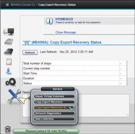
Figure 8-144 Copy Export Recovery Status window
|
Important: The Copy Export recovery status is only available in a single cluster configuration for a TS7700 grid.
|
The table on this page displays the progress of the current Copy Export recovery operation. This page includes the following information:
Total number of steps
The total number of steps that are required to complete the Copy Export recovery operation.
The total number of steps that are required to complete the Copy Export recovery operation.
Current step number
The number of steps completed. This value is a fraction of the total number of steps required to complete, not a fraction of the total time that is required to complete.
The number of steps completed. This value is a fraction of the total number of steps required to complete, not a fraction of the total time that is required to complete.
Start time The time stamp for the start of the operation.
Duration The amount of time the operation has been in progress, in hours, minutes, and seconds.
Status The status of the Copy Export recovery operation. The following values are possible:
No task No Copy Export operation is in progress.
In progress The Copy Export operation is in progress.
Complete with success
The Copy Export operation completed successfully.
The Copy Export operation completed successfully.
Canceled The Copy Export operation was canceled.
Complete with failure The Copy Export operation failed.
Canceling The Copy Export operation is in the process of cancellation.
Operation details This field displays informative status about the progress of the Copy Export recovery operation.
Cancel Recovery Click the Cancel Recovery button to end a Copy Export recovery operation that is in progress and erase all virtual and physical data. The Confirm Cancel Operation dialog box opens to confirm your decision to cancel the operation. Click OK to cancel the Copy Export recovery operation in progress. Click Cancel to resume the Copy Export recovery operation.
8.3 Common procedures
This section describes how to run some tasks necessary during the implementation stage of the TS7700 Virtualization Engine, stand-alone or in grid mode. Some procedures described here might also be useful later during the lifecycle of the TS7700 Virtualization Engine, when a change in configuration or operational parameter is necessary for the operation of the subsystem to the new requirements.
The tasks are grouped by these criteria:
•Procedures related to the TS3500 Tape Library connected to a TS7740 or a TS7720T
•Procedures used only with TS7740 or TS7720T Virtualization Engine
•Procedures used with all TS7700 Virtualization Engine.
8.3.1 TS3500 Tape Library with a TS7740 and TS7720T Virtualization Engine
The following sections describe configuring a TS7740 and TS7720T Virtualization Engine with a TS3500 Tape Library.
Defining a logical library
The TS3500 Tape Library Specialist is required to define a logical library and run the following tasks. Therefore, ensure that it is set up properly and working. For access through a standard-based web browser, an IP address must be configured. This is done initially by the SSR during the hardware installation at the TS3500 Tape Library operator window.
|
Important:
•Each TS7740 or TS7720T Virtualization Engine requires its own logical library in a TS3500 Tape Library.
•The ALMS feature must be installed and enabled to define a logical library partition in the TS3500 Tape Library.
|
Ensure that ALMS is enabled
Before enabling ALMS, the ALMS license key must be entered through the TS3500 Tape Library Operator window because ALMS is a chargeable feature.
You can check the status of ALMS with the TS3500 Tape Library Specialist by selecting Library → ALMS, as shown in Figure 8-145.
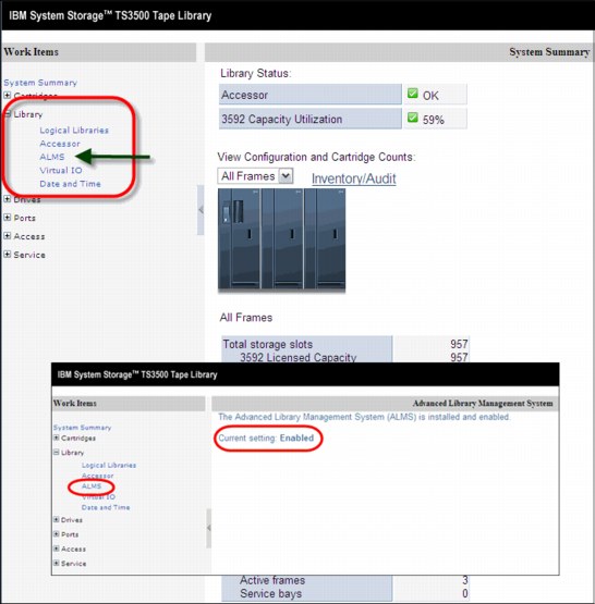
Figure 8-145 TS3500 Specialist System Summary and ALMS windows
When ALMS is enabled for the first time in a partitioned TS3500 Tape Library, the contents of each partition are migrated to ALMS logical libraries. When enabling ALMS in a non-partitioned TS3500 Tape Library, cartridges that are already in the library are migrated to the new ALMS single logical library.
Creating a new logical library with ALMS
This function is valid and available only if ALMS is enabled. Complete these steps:
1. From the main section of the TS3500 Tape Library Specialist Welcome window, go to the work items on the left side of the window and click Library → Logical Libraries, as shown in Figure 8-146.
|
Tip: You can create or remove a logical library from the TS3500 Tape Library by using the Tape Library Specialist web interface.
|
2. From the Select Action menu, select Create and click Go.

Figure 8-146 Create logical library starting window
An extra window, named Create Logical Library, opens. Both windows are shown in Figure 8-147.

Figure 8-147 Create Logical Library windows
3. Type the logical library name (up to 15 characters), select the media type (3592 for TS7740), and then click Apply. The new logical library is created and is displayed in the logical library list when the window is refreshed.
4. After the logical library is created, you can display its characteristics by selecting Library → Logical Libraries under work items on the left side of the window, as shown in Figure 8-148.
5. From the Select Action menu, select Details and then click Go.

Figure 8-148 Recording of the starting SCSI element address of a logical library
In the Logical Library Details window, you see the element address range. The starting element address of each newly created logical library starts one element higher, such as in the following examples:
•Logical Library 1: Starting SCSI element address is 1025.
•Logical Library 2: Starting SCSI element address is 1026.
•Logical Library 3: Starting SCSI element address is 1027.
Setting the maximum cartridges for the logical library
Define the maximum number of cartridge slots for the new logical library. If multiple logical libraries are defined, you can define the maximum number of tape library cartridge slots for each logical library. This enables a logical library to grow without changing the configuration each time you want to add empty slots.
To define the quantity of cartridge slots, complete the following steps:
1. Select a new logical library from the list.
2. From the menu, select Maximum Cartridges and then click Go.
Figure 8-149 shows the web interface windows.

Figure 8-149 Defining the maximum number of cartridges
Setting eight-character Volser option in the new logical library
Check the new logical library for the eight-character Volser reporting option. Go to the Manage Logical Libraries window under Library in the Tape Library Web Specialist, as shown in Figure 8-150.

Figure 8-150 Check Volser reporting option
If the new logical library does not show 8 in the Volser column, correct the information.
Adding drives to the logical library
From the Logical Libraries window shown in Figure 8-148 on page 484, use the work items on the left side of the window to go to the requested web page by selecting Drives → Drive Assignment.
|
Restriction: No intermix of tape drive models is supported by TS7740. The only exception is 3592-E05 Tape Drives working in J1A emulation mode and 3592-J1A Tape Drives (the first and second generation of the 3592 Tape Drives).
TS1130 (3592 Model E06) and TS1140 (3592 Model E07) cannot be intermixed with any other model of 3592 Tape Drive within the same TS7740 or TS7720T.
|
This link takes you to a filtering window where you can select to have the drives displayed by drive element or by logical library. Upon your selection, a window opens so that you can add a drive to or remove a drive from a library configuration. It also enables you to share a drive between Logical Libraries and define its drive as a control path.
|
Restriction: Do not share drives belonging to a TS7720T or TS7740. They must be exclusive.
|
Figure 8-151 shows the drive assignment window of a logical library that has all drives assigned.
Unassigned drives appear in the Unassigned column with the box checked. To assign them, select the appropriate drive box under the logical library name and click Apply.
Click the Help link at the upper-right corner of the window shown in Figure 8-151 to see extended help information, such as detailed explanations of all the fields and functions of the window. The other TS3500 Tape Library Specialist windows provide similar help support.
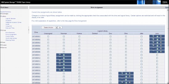
Figure 8-151 Drive Assignment window
In a multi-platform environment, you see logical libraries as shown in Figure 8-151. You can reassign physical tape drives from one logical library to another. You can easily do this for the Open Systems environment, where the tape drives attach directly to the host systems without a tape controller or VTS/TS7700 Virtualization Engine.
|
Restriction: Do not change drive assignments if they belong to an operating TS7740, TS7720T, or tape controller. Work with your IBM SSR, if necessary.
|
In a System z environment, a tape drive always attaches to one tape control unit only. If you change the assignment of a tape drive from a TS7720T or TS7740 Virtualization Engine, the control unit needs to be reconfigured accordingly to reflect the change. Otherwise, the missing resource is reported as defective to the MI and hosts. Work with your IBM SSRs to perform these tasks in a proper way, avoiding unplanned outages.
|
Important: In a System z environment, use the Drive Assignment window only for these functions:
•Initially assign the tape drives from TS3500 Tape Library Web Specialist to a logical partition.
•Assign more tape drives after they have been attached to the TS7740 Virtualization Engine or a tape controller.
•Remove physical tape drives from the configuration after they are physically detached from the TS7740 Virtualization Engine or tape controller.
In addition, never disable ALMS at the TS3500 Tape Library after it has been enabled for System z host support and System z tape drive attachment.
|
Defining control path drives
Each TS7740 Virtualization Engine requires four control path drives defined. If possible, distribute the control path drives over more than one TS3500 Tape Library frame to avoid single points of failure.
In a logical library, you can designate any dedicated drive to become a control path drive. A drive that is loaded with a cartridge cannot become a control path until you remove the cartridge. Similarly, any drive that is a control path cannot be disabled until you remove the cartridge that it contains.
The definition of the control path drive is specified on the Drive Assignment window shown in Figure 8-152. The drives, defined as control paths, are identified by the symbol on the left side of the drive box. You can change the control path drive definition by selecting or clearing this symbol.

Figure 8-152 Control Path symbol
Defining the Encryption Method for the new logical library
After adding tape drives to the new logical library, you must specify the Encryption Method for the new logical library (if applicable).
|
Reminders:
•When using encryption, tape drives must be set to Native mode.
•To activate encryption, FC9900 must have been ordered for the TS7400 or the TS7720T, and the license key must be installed. In addition, the associated tape drives must be Encryption Capable 3592-E05, 3592-E06, or 3952-E07 (although it is supported, 3592-J1A is unable to encrypt data).
|
Complete the following steps:
1. Check the drive mode by opening the Drives summary window in the TS3500 MI, as shown in Figure 8-153, and look in the Mode column. This column is displayed only if drives in the tape library are emulation-capable.

Figure 8-153 Drive mode
2. If necessary, change the drive mode to Native mode (3592-E05 only). In the Drives summary window, select a drive and select Change Emulation Mode, as shown in Figure 8-154.
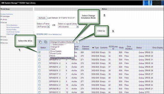
Figure 8-154 Changing drive emulation
3. In the next window that opens, select the native mode for the drive. After the drives are in the wanted mode, proceed with the Encryption Method definition.
4. In the TS3500 MI, click Library → Logical Libraries, select the logical library with which you are working, select Modify Encryption Method, and then click Go. See Figure 8-155.

Figure 8-155 Selecting the Encryption Method
5. In the window that opens, select System-Managed for the chosen method, and select all drives for this partition. See Figure 8-156.
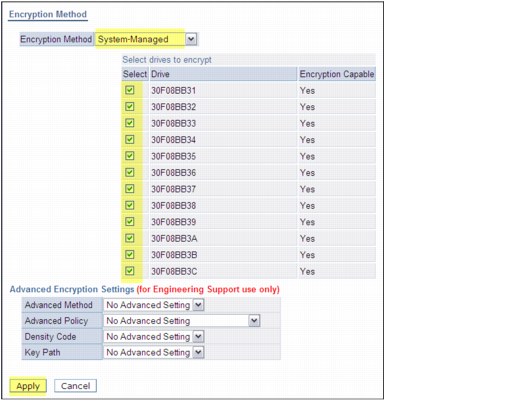
Figure 8-156 Setting the Encryption Method
To make encryption fully operational in the TS7740 configuration, more steps are necessary. Work with your IBM SSR to configure the Encryption parameters in the TS7740 during the installation process.
|
Important: Keep the Advanced Encryption Settings as NO ADVANCED SETTING, unless set otherwise by IBM Engineering.
|
Defining Cartridge Assignment Policies
The Cartridge Assignment Policy (CAP) of the TS3500 Tape Library is where you can assign ranges of physical cartridge volume serial numbers to specific logical libraries. If you have previously established a CAP and place a cartridge with a VOLSER that matches that range into the I/O station, the library automatically assigns that cartridge to the appropriate logical library.
Select Cartridge Assignment Policy from the Cartridges work items to add, change, and remove policies. The maximum quantity of Cartridge Assignment Policies for the entire TS3500 Tape Library must not exceed 300 policies.
Figure 8-157 shows the VOLSER ranges defined for logical libraries.
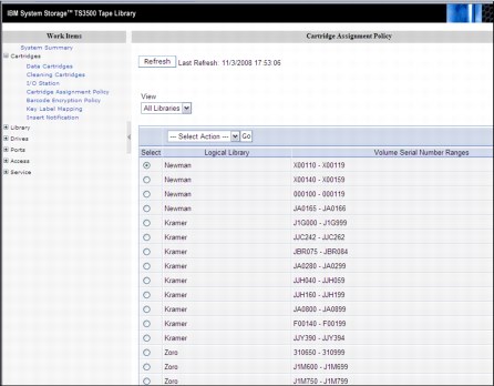
Figure 8-157 TS3500 Tape Library Cartridge Assignment Policy
The TS3500 Tape Library enables duplicate VOLSER ranges for different media types only. For example, Logical Library 1 and Logical Library 2 contain Linear Tape-Open (LTO) media, and Logical Library 3 contains IBM 3592 media. Logical Library 1 has a Cartridge Assignment Policy of ABC100-ABC200. The library rejects an attempt to add a Cartridge Assignment Policy of ABC000-ABC300 to Logical Library 2 because the media type is the same (both LTO). However, the library does enable an attempt to add a Cartridge Assignment Policy of ABC000-ABC300 to Logical Library 3 because the media (3592) is different.
In a storage management subsystem (SMS)-managed z/OS environment, all VOLSER identifiers across all storage hierarchies are required to be unique. Follow the same rules across host platforms also, whether you are sharing a TS3500 Tape Library between System z and Open Systems hosts or not.
|
Tip: The Cartridge Assignment Policy does not reassign an already assigned tape cartridge. If needed, you must first unassign it, then manually reassign it.
|
Inserting TS7740 or TS7720T Virtualization Engine physical volumes
The TS7740 or TS7720T Virtualization Engine subsystem manages both logical and physical volumes. The Cartridge Assignment Policy (CAP) of the TS3500 Tape Library only affects the physical volumes associated with this TS7740 or TS7720T Virtualization Engine logical library. Logical Volumes are managed from the TS7700 Virtualization Engine MI only.
Complete the following steps to add physical cartridges:
1. Define Cartridge Assignment Policies at the TS3500 Tape Library level by using ALMS through the Web Specialist. This process ensures that all TS7700 Virtualization Engine ranges are recognized and assigned to the correct TS3500 Tape Library logical library partition (the logical library created for this specific TS7700 Virtualization Engine) before you begin any TS7700 Virtualization Engine MI definitions.
2. Physically insert volumes into the library by using the I/O station, or by opening the library and placing cartridges in empty storage cells. Cartridges are assigned to the TS7740 or TS7720T logical library partitions according to the definitions.
|
Important: Before inserting TS7740 or TS7720T Virtualization Engine physical volumes into the tape library, ensure that the VOLSER ranges are defined correctly at the TS7700 MI. For more information, see “Defining VOLSER ranges for physical volumes” on page 498.
|
These procedures ensure that TS7700 Virtualization Engine back-end cartridges are never assigned to a host by accident. Figure 8-158 shows the flow of physical cartridge insertion and assignment to logical libraries for TS7740 or TS7720TVirtualization Engine.
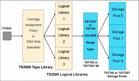
Figure 8-158 Volume assignment
Inserting physical volumes into the TS3500 Tape Library
Two methods are available for inserting physical volumes into the TS3500 Tape Library:
•Opening the library doors and inserting the volumes directly into the tape library storage empty cells (bulk loading)
•Using the TS3500 Tape Library I/O station
Insertion directly into storage cells
Use the operator pane of the TS3500 to pause it. Open the door and insert the cartridges into any empty slot, except those slots reserved for diagnostic cartridges, which are Frame 1, Column 1 in the first Row (F01, C01, and R01) in a single media-type library. Also do not insert cartridges in the shuffle locations in the high-density frames (top two first rows in the HD frame). Always use empty slots in the same frame whose front door was opened, otherwise the cartridges will not be inventoried.
|
Important: With ALMS enabled, cartridges that are not in a CAP are not added to any logical library.
|
After completing the new media insertion, close the doors. After approximately 15 seconds, the TS3500 automatically inventories the frame or frames of the door you opened. During the inventory, the message INITIALIZING is displayed on the Activity window on the operator window. When the inventory completes, the TS3500 operator window displays a Ready state.
The TS7740 or TS7720T Virtualization Engine uploads its logical library inventory and updates its Integrated Library Manager inventory. After completing this operation, the TS7700 cluster Library reaches the Auto state.
|
Tip: Only place cartridges in a frame whose front door is open. Do not add or remove cartridges from an adjacent frame.
|
Insertion by using the I/O station
With the ALMS, your TS3500 can be operating with or without virtual I/O being enabled. The procedure varies depending on which mode is active in the library.
Basically, with virtual I/O (VIO) enabled, TS3500 moves the cartridges from the physical I/O station into the physical library by itself. In the first moment, the cartridge leaves the physical I/O station and goes into a slot mapped as a virtual I/O - SCSI element between 769 (X’301’) and 1023 (X’3FF’) for the logical library selected by the CAP.
Each logical library has its own set of up to 256 VIO slots. This is defined in the logical library creation, and can be altered later, if needed.
With VIO disabled, the TS3584 does not move cartridges from the physical I/O station unless it receives a command from the TS7740 or TS7720T Virtualization Engine or any other controlling host.
In both cases, the TS3500 detects the volumes inserted when the I/O station door is closed and scans all I/O cells using the bar code reader. The CAP decides to which logical library those cartridges belong and then runs one of the following tasks:
•Moves them to that logical library’s virtual I/O slots, if VIO is enabled.
•Waits for a host command in this logical partition. The cartridges stay in the I/O station after the bar code scan.
Because the inserted cartridges belong to a defined range in the CAP of this logical library, and those ranges were defined in the TS7700 Virtualization Engine Physical Volume Range as explained in “Defining VOLSER ranges for physical volumes” on page 498, those cartridges are assigned to this logical library.
If any VOLSER is not in the range defined by the CAP, the operator must identify the correct logical library as the destination by using the Insert Notification window at the operator window. If Insert Notification is not answered, the volume remains unassigned.
|
Restriction: Insert Notification is not supported on a high-density library. If a cartridge outside the CAP-defined ranges is inserted, it remains unassigned without any notification.
|
Verify that the cartridges were correctly assigned by using the TS3500 MI. Click Cartridges → Data Cartridges and select the appropriate logical library. If everything is correct, the inserted cartridges are listed. Alternatively, displaying the Unassigned/Shared volumes show none. See Figure 8-159.

Figure 8-159 Checking volume assignment
Unassigned volumes in the TS3500 Tape Library
If a volume does not match the definitions in the CAP, and if during the Insert Notification process no owner was specified, the cartridge remains unassigned in the TS3500 Tape Library. You can check for unassigned cartridges:
1. Use the TS3500 MI and select Cartridges → Data Cartridges.
3. You can then assign the cartridges to the TS7700 Virtualization Engine logical library partition by following the procedure in “Assigning cartridges in the TS3500 Library to the logical library partition” on page 495.
|
Important: Unassigned cartridges can exist in the TS3500 Tape Library, and in the TS7700 Virtualization Engine MI. However, unassigned has separate meanings and requires separate actions from the operator in each system.
|
Unassigned volumes in TS7740 or TS7720T Virtualization Engine
A physical volume goes to the Unassigned category in the TS7740 or TS7720T Virtualization Engine if it does not fit in any defined range of physical volumes for this TS7700 cluster. Defined Ranges and Unassigned Volumes can be checked in the TS7700 MI Physical Volume Ranges window shown in Figure 8-160.
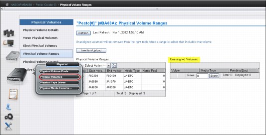
Figure 8-160 TS7740 unassigned volumes
If an unassigned volume should be assigned to this TS7740 or TS7720T Virtualization Engine, a new range that includes this volume must be created, as described in “Defining VOLSER ranges for physical volumes” on page 498. If this volume was incorrectly assigned to the TS7700 cluster, you must eject and reassign it to the proper logical library in the TS3500 Tape Library. Also, double-check the CAP definitions in the TS3500 Tape Library.
Assigning cartridges in the TS3500 Library to the logical library partition
This procedure is necessary only if a cartridge was inserted, without CAP being provided in advance. To use this procedure, you must assign the cartridge manually to a logical library in the TS3500 Tape Library.
|
Clarifications:
•Insert Notification is not supported in a high-density library. The CAP must be correctly configured to provide automated assignment of all the inserted cartridges.
•A cartridge that has been manually assigned to the TS7700 Logical Library does not display automatically in the TS7740 or TS7720T inventory. An Inventory Upload is needed to refresh the TS7700 cluster inventory. The Inventory Upload function is available on the Physical Volume Ranges menu as shown in Figure 8-160.
•Cartridge assignment to a logical library is available only through the TS3500 Tape Library Specialist web interface. The operator window does not provide this function.
|
Assigning a data cartridge
To assign a data cartridge to a logical library in the TS3500 Tape Library, complete these steps:
1. Open the Tape Library Specialist web interface (go to the library’s Ethernet IP address or the library URL using a standard browser). The Welcome window opens.
2. Click Cartridges → Data Cartridges. The Data Cartridges window opens.
3. Select the logical library to which the cartridge is assigned and select how you want the cartridge range to be sorted. The library can sort the cartridge by volume serial number, SCSI element address, or frame, column, and row location. Click Search. The Cartridges window opens and shows all the ranges for the logical library that you specified.
4. Select the range that contains the data cartridge that you want to assign.
5. Select the data cartridge and then click Assign.
6. Select the logical library partition to which you want to assign the data cartridge.
7. Click Next to complete the function.
8. For a TS7740 or TS7720T Virtualization Engine cluster, click Physical → Physical Volumes → Physical Volume Ranges and click Inventory Upload, as shown in Figure 8-160 on page 495.
Inserting a cleaning cartridge
Each drive in the TS3500 Tape Library requires cleaning from time to time. Tape drives used by the TS7700 subsystem can request a cleaning action when necessary. This cleaning is carried out by the TS3500 Tape Library automatically. However, you must provide the necessary cleaning cartridges.
|
Remember:
•TS7740 or TS7720T requires ALMS to be installed and enabled in the TS3500 Tape Library. ALMS sets cleaning mode to automatic. Therefore, library manages drive cleaning.
•A cleaning cartridge is good for 50 cleaning actions.
|
The process to insert cleaning cartridges varies depending on the setup of the TS3500 Tape Library. A cleaning cartridge can be inserted by using the web interface or from the operator window. As many as 100 cleaning cartridges can be inserted in a TS3500 Tape Library.
To insert a cleaning cartridge using the TS3500 Tape Library Specialist, complete the following steps:
1. Open the door of the I/O station and insert the cleaning cartridge.
2. Close the door of the I/O station.
3. Enter the Ethernet IP address on the URL line of the browser. The Welcome Page opens.
4. Click Cartridges → I/O Station. The I/O Station window opens.
5. Follow the instructions in the window.
To insert a cleaning cartridge by using the operator window, complete the following steps:
1. From the Library’s Activity touchscreen, press MENU → Manual Operations → Insert Cleaning Cartridges → Enter. The library displays the message Insert Cleaning Cartridge into I/O station before you continue. Do you want to continue?
2. Open the I/O station and insert the cleaning cartridge. If you insert it incorrectly, the I/O station does not close properly. Do not force it.
3. Close the I/O station and click Yes. The tape library scans the I/O station for the cartridges and moves them to an appropriate slot. The tape library displays the message Insertion of Cleaning Cartridges has completed.
4. Press Enter to return to Manual Operations menu, and Back until you return to the Activity touchscreen.
|
Tip: Cleaning cartridge are not assigned to specific logical libraries.
|
Removing cleaning cartridges from a TS3500 Tape Library
This section describes how to remove a cleaning cartridge by using the TS3500 Tape Library Specialist. You can also use the operator window. For more information, see IBM System Storage TS3500 Tape Library with ALMS Operator Guide, GA32-0594.
To use the TS3500 Tape Library Specialist web interface to remove a cleaning cartridge from the tape library, complete the following steps:
1. Type the Ethernet IP address on the URL line of the browser and press Enter. The System Summary window opens.
3. Select a cleaning cartridge. From the Select Action menu, select Remove, and then
click Go.
click Go.
4. Look at the Activity pane in the operator window to determine whether the I/O station that you want to use is locked or unlocked. If the station is locked, use your application software to unlock it.
5. Open the door of the I/O station and remove the cleaning cartridge.
6. Close the door of the I/O station.
Determine the cleaning cartridge usage in the TS3500 Tape Library
You can determine the usage of the cleaning cartridge in the same window that is used for the removal of the cleaning cartridges. See the Cleans Remaining column shown in Figure 8-161.

Figure 8-161 TS3500 Tape Library cleaning cartridges
8.3.2 TS7740 or TS7720T Virtualization Engine definitions
This section provides information about the following definitions:
Defining VOLSER ranges for physical volumes
After a cartridge is assigned to a logical library that is associated to a TS7740 or TS7720T Virtualization Engine by CAPs, it is presented to the TS7700 Virtualization Engine Integrated Library Manager. The Integrated Library Manager uses the VOLSER ranges that are defined in its VOLSER Ranges table to set it to a proper Library Manager category. Define the proper policies in the VOLSER Ranges table before inserting the cartridges into the tape library.
|
Important:
•When using a TS3500 Tape Library, you must assign the CAP at the library hardware level before using the library with System z hosts.
•When using a TS3500 Tape Library and the TS7740 or TS7720T Virtualization Engine, physical volumes must fall within ranges that are assigned by the CAP to the Logical Library belonging to this cluster in the TS3500 Tape Library.
|
Use the window shown in Figure 8-162 to add, modify, and delete physical volume ranges. Unassigned physical volumes are listed in this window. When you observe an unassigned volume that belongs to this TS7700 Virtualization Engine, add a range that includes that volume to fix it. If an unassigned volume does not belong to this TS7700 cluster, you must eject it and reassign it to the proper logical library in the TS3500 Tape Library.

Figure 8-162 Physical Volume Ranges window
Click Inventory Upload to upload the inventory from the TS3500 and update any range or ranges of physical volumes that were recently assigned to that logical library. The VOLSER Ranges table displays the list of defined VOLSER ranges for a specific component. You can use the VOLSER Ranges table to create a new VOLSER range, or to modify or delete a predefined VOLSER range.
|
Important: Operator intervention is required to resolve unassigned volumes.
|
Figure 8-162 on page 498 shows the status information that is displayed in the VOLSER Ranges table:
•Start Volser: The first VOLSER in a defined range
•End Volser: The last VOLSER in a defined range
•Media Type: The media type for all volumes in a certain VOLSER range. The following values are valid:
– JA-ETC: Enterprise Tape Cartridge
– JB-ETCL: Enterprise Extended-Length Tape Cartridge
– JC-EADC: Enterprise Advanced Data Cartridge
– JJ-EETC: Enterprise Economy Tape Cartridge
– JK-EAETC: Enterprise Advanced Economy Tape Cartridge
•Home Pool: The home pool to which the VOLSER range is assigned
Use the menu in the VOLSER Ranges table to add a VOLSER range, or to modify or delete a predefined range:
•To add a VOLSER range, select Add from the menu. Complete the fields for information that you want displayed in the VOLSER Ranges table, as defined previously.
•To modify a predefined VOLSER range, click the radio button from the Select column in the same row as the name of the VOLSER range you want to modify. Select Modify from the menu and make your changes to the information that you want displayed in the VOLSER Ranges table.
|
Important: Modifying a predefined VOLSER range will not affect physical volumes
that are already inserted and assigned to the TS7740 or TS7720T Virtualization Engine. Only physical volumes that are inserted after the VOLSER range modification are changed. |
The VOLSER entry fields must contain six characters. The characters can be letters, numerals, or a space. The two VOLSERs must be entered in the same format. Corresponding characters in each VOLSER must both be either alphabetic or numeric. For example, AAA998 and AAB004 are of the same form, but AA9998 and AAB004 are not.
The VOLSERs that fall within a range are determined in the following manner. The VOLSER range is increased so that alphabetic characters are increased alphabetically, and numeric characters are increased numerically. For example, VOLSER range ABC000 - ABD999 results in a range of 2,000 VOLSERs (ABC000 - ABC999 and ABD000 - ABD999).
|
Restriction: VOLSER ranges defined at the IBM TS3500 Tape Library user interface refer exclusively to physical cartridges. Logical Volumes are defined only through the TS7700 Virtualization Engine MI. See “Inserting virtual volumes” on page 514 for more information.
|
For the TS7700 Virtualization Engine, no additional definitions are required at the hardware level other than setting up the correct VOLSER ranges at the TS3500 library.
Although you can now enter cartridges into the TS3500 library, complete the required definitions at the host before you insert any physical cartridges into the tape library.
Defining physical volume pools in the TS7740 or TS7720T
Physical volume pooling was first introduced as part of advanced policy management advanced functions in the IBM TotalStorage Virtual Tape Server (VTS).
Pooling physical volume enables you to place your data into separate sets of physical media, treating each media group in a specific way. For instance, you might want to segregate production data from test data, or encrypt part of your data. All of this can be accomplished by defining physical volume pools appropriately. Also, you can define the reclaim parameters for each specific pool to best suit your specific needs. The TS7700 Virtualization Engine MI is used for pool property definitions.
Items under Physical Volumes in the MI apply only to clusters with an associated tape library (TS7740 or TS7720T Virtualization Engine). Trying to access those windows from a TS7720 results in the following HYDME0995E message:
This cluster is not attached to a physical tape library.
Use the window shown in Figure 8-163 to view or modify settings for physical volume pools, which manage the physical volumes used by the TS7700 Virtualization Engine.

Figure 8-163 Physical Volume Pools
The Physical Volume Pool Properties table displays the encryption setting and media properties for every physical volume pool defined for TS7740 or TS7720T clusters in the grid.
You can use the Physical Volume Pool Properties table to view encryption and media settings for all installed physical volume pools. To view and modify more pool properties, select a pool or pools from this table and then select either Modify Pool Properties or Modify Encryption Settings from the menu.
|
Tip: Pools 1 - 32 are preinstalled. Pool 1 functions as the default pool and is used if no other pool is selected.
|
The Physical Volume Pool Properties table displays the media properties and encryption settings for every physical volume pool defined for each cluster in the grid. This table contains two tabs: Pool Properties and Physical Tape Encryption Settings.
These two tabs contain the following information:
•The following information is under the Pool Properties tab:
– Pool: Lists the pool number, which is a whole number 1 - 32, inclusive.
– Media Class: Lists that the supported media class of the storage pool is 3592.
– First Media (Primary): The primary media type that the pool can borrow or return to the common scratch pool (Pool 0). The following values are valid:
Any 3592 Any 3592
JA Enterprise Tape Cartridge (ETC)
JB Enterprise Extended-Length Tape Cartridge (ETCL)
JC Enterprise Advanced Data Cartridge (EADC)
JJ Enterprise Economy Tape Cartridge (EETC)
JK Enterprise Advanced Economy Tape Cartridge (EAETC)
To modify pool properties, select the check box next to one or more pools listed in the Physical Volume Pool Properties table and select Properties from the menu. The Pool Properties table is displayed.
You can modify the fields Media Class and First Media, defined previously, and the following fields:
– Second Media (Secondary): Lists the second choice of media type from which the pool can borrow. The options listed exclude the media type selected for the First Media. The following values are valid:
Any 3592 Any 3592
JA Enterprise Tape Cartridge (ETC)
JB Enterprise Extended-Length Tape Cartridge (ETCL)
JC Enterprise Advanced Data Cartridge (EADC)
JJ Enterprise Economy Tape Cartridge (EETC)
JK Enterprise Advanced Economy Tape Cartridge (EAETC)
None The only option available if the Primary Media type is Any 3592
– Borrow Indicator: Defines how the pool is populated with scratch cartridges. The following values are valid:
Borrow, Return A cartridge is borrowed from the common scratch pool and returned when emptied.
Borrow, Keep A cartridge is borrowed from the common scratch pool and retained, even after being emptied.
No Borrow, Return A cartridge cannot be borrowed from the common scratch pool, but an emptied cartridge is placed in the common scratch pool. This setting is used for an empty pool.
No Borrow, Keep A cartridge cannot be borrowed from the common scratch pool, and an emptied cartridge is retained.
– Reclaim Pool: Lists the pool to which logical volumes are assigned when reclamation occurs for the stacked volume on the selected pool.
– Maximum Devices: Lists the maximum number of physical tape drives that the pool can use for premigration.
– Export Pool: Lists the type of export that is supported if the pool is defined as an Export Pool, which is the pool from which physical volumes are exported:
i. From the Physical Volume Pools window, click the Pool Properties tab.
ii. Select the check box next to each pool to be modified.
iii. Select Modify Pool Properties from the Physical volume pools menu.
iv. Click Go to open the Modify Pool Properties page.
The following values are valid:
Not Defined The pool is not defined as an Export pool.
Copy Export The pool is defined as a Copy Export pool.
– Export Format: The media format used when writing volumes for export. This function can be used when the physical library recovering the volumes supports a different media format than the physical library exporting the volumes. This field is only enabled if the value in the Export Pool field is Copy Export. The following values are valid:
Default The highest common format supported across all drives in the library. This is also the default value for the Export Format field.
E06 Format of a 3592-E06 Tape Drive.
E07 Format of a 3592-E07 Tape Drive.
– Days Before Secure Data Erase: Lists the number of days a physical volume that is a candidate for Secure Data Erase can remain in the pool without access to a physical stacked volume. Each stacked physical volume possesses a timer for this purpose, which is reset when a logical volume on the stacked physical volume is accessed. Secure Data Erase occurs later, based on an internal schedule. Secure Data Erase renders all data on a physical stacked volume inaccessible. The valid range of possible values is 1 - 365. Clicking to clear the check box deactivates this function.
– Days Without Access: Lists the number of days that the pool can persist without access to a physical stacked volume. Each physical stacked volume has a timer for this purpose, which is reset when a logical volume is accessed. The reclamation occurs later, based on an internal schedule. The valid range of possible values is 1 - 365. Clicking to clear the check box deactivates this function.
– Age of Last Data Written: Lists the number of days the pool has persisted without write access to set a physical stacked volume as a candidate for reclamation. Each physical stacked volume has a timer for this purpose, which is reset when a logical volume is accessed. The reclamation occurs later, based on an internal schedule. The valid range of possible values is 1 - 365. Clicking to clear the check box deactivates
this function.
this function.
– Days Without Data Inactivation: Lists the number of sequential days the pool’s data ratio has been higher than the Maximum Active Data to set a physical stacked volume as a candidate for reclamation. Each physical stacked volume has a timer for this purpose, which is reset when data is deactivated. The reclamation occurs later, based on an internal schedule. The valid range of possible values is 1-365. Clicking to clear the check box deactivates this function. If deactivated, this field is not used as a criteria for reclamation.
– Maximum Active Data: Lists the ratio of the amount of active data in the entire physical stacked volume capacity. This field is used with Days Without Data Inactivation. The valid range of possible values is 5% - 95%. This function is disabled if Days Without Data Inactivation is not selected.
– Reclaim Threshold: Lists the percentage that is used to determine when to reclaim free storage on a stacked volume. When the amount of active data on a physical stacked volume drops below this percentage, a reclaim operation is run on the stacked volume. The valid range of possible values is 5% - 95%. The default value is 10%. Clicking to clear the check box deactivates this function.
•The following information is under the Physical Tape Encryption Settings tab:
– Pool: Lists the pool number. This number is a whole number 1 - 32, inclusive.
– Encryption: Lists the encryption state of the pool. The possible values are Enabled and Disabled.
– Key Mode 1: Lists the encryption mode used with Key Label 1. The following values are valid for this field:
• Clear Label: The data key is specified by the key label in clear text.
• Hash Label: The data key is referenced by a computed value corresponding to its associated public key.
• None: Key Label 1 is disabled.
• Dash (-): The default key is in use.
– Key Label 1: Lists the current encryption key Label 1 for the pool. The label must consist of ASCII characters and cannot exceed 64 characters. Leading and trailing blanks are removed, but an internal space is allowed. Lowercase characters are internally converted to uppercase upon storage, so key labels are reported using uppercase characters. If the encryption state indicates Disabled, this field is blank. If the default key is used, the value in this field is default key.
– Key Mode 2: Lists the encryption mode used with Key Label 2. The following values are valid for this field:
• Clear Label: The data key is specified by the key label in clear text.
• Hash Label: The data key is referenced by a computed value corresponding to its associated public key.
• None: Key Label 2 is disabled.
• Dash (-): The default key is in use.
– Key Label 2: The current encryption key Label 2 for the pool. The label must consist of ASCII characters and cannot exceed 64 characters. Leading and trailing blanks are removed, but an internal space is allowed. Lowercase characters are internally converted to uppercase upon storage, so key labels are reported using uppercase characters. If the encryption state is Disabled, this field is blank. If the default key is used, the value in this field is default key.
To modify encryption settings for one or more physical volume pools, complete the following steps:
1. Open the Physical Volume Pools page (Figure 8-164).

Figure 8-164 Modifying encryption parameters for a pool
|
Tip: A tutorial is available at the Physical Volume Pools page to show you how to modify encryption properties.
|
2. Click the Physical Tape Encryption Settings tab.
3. Select the check box next to each pool to be modified.
4. Click Select Action → Modify Encryption Settings.

Figure 8-165 Modify encryption settings parameters
In this window, you can modify values for any of the following controls:
– Encryption
This field is the encryption state of the pool and can have the following values:
• Enabled: Encryption is enabled on the pool.
• Disabled: Encryption is not enabled on the pool.
When this value is selected, key modes, key labels, and check boxes are disabled.
– Use Encryption Key Manager default key
Select this check box to populate the Key Label field by using a default key provided by the encryption key manager.
|
Restriction: Your encryption key manager software must support default keys to use this option.
|
This check box occurs before both Key Label 1 and Key Label 2 fields. You must select this check box for each label to be defined using the default key.
If this check box is selected, the following fields are disabled:
• Key Mode 1
• Key Label 1
• Key Mode 2
• Key Label 2
– Key Mode 1
This field is the encryption mode that is used with Key Label 1. The following values
are valid:
are valid:
• Clear Label: The data key is specified by the key label in clear text.
• Hash Label: The data key is referenced by a computed value corresponding to its associated public key.
• None: Key Label 1 is disabled. The default key is in use.
– Key Label 1
This field is the current encryption key Label 1 for the pool. The label must consist of ASCII characters and cannot exceed 64 characters. Leading and trailing blanks are removed, but an internal space is allowed. Lowercase characters are internally converted to uppercase upon storage, so key labels are reported using uppercase characters.
– Key Mode 2
This field is the encryption mode used with Key Label 2. The following values are valid:
• Clear Label: The data key is specified by the key label in clear text.
• Hash Label: The data key is referenced by a computed value that corresponds to its associated public key.
– None
Indicates that the Key Label 2 is disabled. The default key is in use.
– Key Label 2
This field is the current encryption key Label 2 for the pool. The label must consist of ASCII characters and cannot exceed 64 characters. Leading and trailing blanks are removed, but an internal space is allowed. Lowercase characters are internally converted to uppercase upon storage, so key labels are reported using uppercase characters.
6. To complete the operation, click OK. To abandon the operation and return to the Physical Volume Pools page, click Cancel.
Defining reclamation settings in a TS7740 or TS7720T
To optimize use of the subsystem resources, such as CPU cycles and tape drive usage, you can inhibit space reclamation during predictable busy periods of time and adjust reclamation thresholds to the optimum point in your TS7740 or TS7720T through the MI. The reclaim threshold is the percentage that is used to determine when to run the reclamation of free space in a stacked volume.
When the amount of active data on a physical stacked volume drops below this percentage, the volume becomes eligible for reclamation. Reclamation values can be in the range of
0% - 95%, with a default value of 35%. Selecting 0% deactivates this function.
0% - 95%, with a default value of 35%. Selecting 0% deactivates this function.
Throughout the data lifecycle, new logical volumes are created and old logical volumes become obsolete. Logical volumes are migrated to physical volumes, occupying real space there. When a logical volume becomes obsolete, that space becomes a waste of capacity in that physical tape. Therefore, the active data level of that volume is decreasing over time.
TS7740 and TS7720T actively monitors the active data in its physical volumes. Whenever this active data level crosses the reclaim threshold that is defined in the Physical Volume Pool in which that volume belongs, the TS7700 places that volume in a candidate list for reclamation.
Reclamation copies active data from that volume to another stacked volume in the same pool. When the copy finishes and the volume becomes empty, the volume is returned to available SCRATCH status. This cartridge is now available for use and is returned to the common scratch pool or directed to the specified reclaim pool, according to the Physical Volume Pool definition.
|
Clarification: Each reclamation task uses two tape drives (source and target) in a tape-to-tape copy function. The TS7700 Tape Volume Cache is not used for reclamation.
|
Multiple reclamation processes can run in parallel. The maximum number of reclaim tasks is limited by the TS7740 and TS7720T, based on the number of available drives as shown in Table 8-13.
Table 8-13 Installed drives versus maximum reclaim tasks
|
Number of available drives
|
Maximum number of reclaims
|
|
3
|
1
|
|
4
|
1
|
|
5
|
1
|
|
6
|
2
|
|
7
|
2
|
|
8
|
3
|
|
9
|
3
|
|
10
|
4
|
|
11
|
4
|
|
12
|
5
|
|
13
|
5
|
|
14
|
6
|
|
15
|
6
|
|
16
|
7
|
The reclamation level for the physical volumes must be set by using the Physical Volume Pools window in the TS7700 MI. See Figure 8-166.

Figure 8-166 Physical Volume Pools
Select a pool and click Modify Pool Properties in the menu to set the reclamation level and other policies for that pool. Figure 8-167 shows the Modify Pool Properties window.
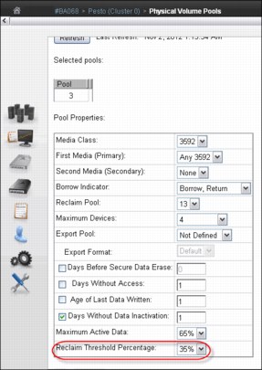
Figure 8-167 Pool properties
The example shows the borrow-return policy in effect for Pool 3, meaning that cartridges can be borrowed from the common scratch pool (and, those cartridges are returned to the CSP upon reclamation). Also, the user has defined that volumes belonging to pool 3 should reclaim into pool 13.
No more than four drives can be used for premigration in pool 3. The reclaiming threshold percentage has been set to 35%, meaning that when a physical volume in pool 3 crosses down the threshold of 35% of occupancy with active data, the stacked cartridge became candidate for reclamation. The other way to trigger a reclamation in this example is Days Without Data Inactivation for tape cartridges with up to 65% of occupancy level.
Reclamation enablement
To minimize any effect on TS7700 Virtualization Engine activity, the storage management software monitors resource use in the TS7700 Virtualization Engine, and enables or disables reclamation as appropriate. You can optionally prevent reclamation activity at specific times of day by specifying an Inhibit Reclaim Schedule in the TS7700 Virtualization Engine MI (Figure 8-168 on page 511 shows an example).
However, the TS7740 or TS7720T Virtualization Engine determines whether reclamation is to be enabled or disabled once an hour, depending on the number of available scratch cartridges. It ignores the Inhibit Reclaim schedule if the TS7740 or TS7720T gets below a minimum number of scratch cartridges available. At this point, reclamation is enforced by the TS7740 or TS7720T.
|
Tip: The maximum number of inhibit reclaim schedules is 14.
|
Using the Bulk Volume Information Retrieval (BVIR) process, you can run the query for PHYSICAL MEDIA POOLS to monitor the amount of active data on stacked volumes to help you plan for a reasonable and effective reclaim threshold percentage. You can also use the Host Console Request function to obtain the physical volume counts.
Although reclamation is enabled, stacked volumes might not always be going through the process all the time. Other conditions must be met, such as stacked volumes that meet one of the reclaim policies and drives available to mount the stacked volumes.
Reclamation for a volume is stopped by the TS7700 Virtualization Engine internal management functions if a tape drive is needed for a recall or copy (because these are of a higher priority) or a logical volume is needed for recall off a source or target tape that is in the reclaim process. If this happens, reclamation is stopped for this physical tape after the current logical volume move is complete.
Pooling is enabled as a standard feature of the TS7700 Virtualization Engine, even if you are using only one pool. Reclamation can occur on multiple volume pools at the same time, and process multiple tasks for the same pool. One of the reclamation methods selects the volumes for processing based on the percentage of active data.
For example, if the reclaim threshold was set to 30% generically across all volume pools, the TS7700 Virtualization Engine selects all the stacked volumes from 0% - 29% of the remaining active data. The reclaim tasks then process the volumes from least full (0%) to most full (29%) up to the defined reclaim threshold of 30%.
Individual pools can have separate reclaim policies set. The number of pools can also influence the reclamation process because the TS7740 or TS7720 Virtualization Engine always evaluates the stacked media starting with Pool 1.
The scratch count for physical cartridges also affects reclamation. The scratch state of pools is assessed in the following manner:
1. A pool enters a Low scratch state when it has access to less than 50 and two or more empty cartridges (scratch tape volumes).
2. A pool enters a Panic scratch state when it has access to fewer than two empty cartridges (scratch tape volumes).
Access to includes any borrowing capability, which means that if the pool is configured for borrowing, and if there are more than 50 cartridges in the common scratch pool, the pool will not enter the Low scratch state.
Whether borrowing is configured or not, if each pool has two scratch cartridges, the Panic Reclamation mode is not entered. Panic Reclamation mode is entered when a pool has fewer than two scratch cartridges and no more scratch cartridges can be borrowed from any other pool defined for borrowing. Borrowing is described in “Using Physical Volume pools” on page 45.
|
Important: A physical volume pool running out of scratch cartridges might stop mounts in the TS7740 or TS7720T tape attach partitions, affecting your operations. Mistakes in pool configuration (media type, borrow and return, home pool, and so on) or operating with an empty common scratch pool might lead to this situation.
|
Consider that one reclaim task uses two drives for the data move, and CPU cycles. When a reclamation starts, these drives are busy until the volume being reclaimed is empty. If you raise the reclamation threshold level too high, the result is larger amounts of data to be moved, with resultant penalty in resources that are needed for recalls and premigration. The default setting for the reclamation threshold level is 35%.
Generally, you need to operate with a reclamation threshold level in the range of 10% - 35%. For more information about fine-tuning this function, considering your peak load and using new host functions, see 4.4.3, “Physical volumes for TS7740 or TS7720 tape attach Virtualization Engine” on page 159. Pools in either scratch state (Low or Panic state) get priority for reclamation.
Table 8-14 summarizes the thresholds.
Table 8-14 Reclamation priority table
|
Priority
|
Condition
|
Reclaim schedule honored
|
Active data threshold% honored
|
Number of concurrent reclaims
|
Comments
|
|
1
|
Pool in Panic scratch state
|
No
|
No
|
At least one, regardless of idle drives. If more idle drives are available, more reclaims are started, up to the maximum limit.
|
|
|
2
|
Priority move
|
Yes or No
|
No
|
At least one, regardless of idle drives. If more idle drives are available, more reclaims are started, up to the maximum limit.
|
If a volume is within 10 days of a Secure Data Erasure and still has active data on it, it is reclaimed at this priority. An SDE priority move accepts the inhibit reclaim schedule.
For a TS7700 MI-initiated priority move, the option to accept the inhibit reclaim schedule is given to the operator.
|
|
3
|
Pool in Low scratch state
|
Yes
|
Yes
|
At least one, regardless of idle drives. If more idle drives are available, more reclaims are started, up to the maximum limit.
|
Volumes that are subject to reclaim because of Maximum Active Data, Days Without Access, Age of Last Data Written, and Days Without Data Inactivation use priority 3 or 4 reclamation.
|
|
4
|
Normal reclaim
|
Yes
|
Yes, pick from all eligible pools
|
(Number of idle drives divided by 2) minus 1
8 drv: 3 max
16 drv: 7 max
|
Volumes that are subject to reclaim because of Maximum Active Data, Days Without Access, Age of Last Data Written, and Days Without Data Inactivation use priority 3 or 4 reclamation.
|
|
Tips:
•A physical drive is considered idle when no activity has occurred for the previous 10 minutes.
•The Inhibit Reclaim schedule is not accepted by the Secure Data Erase function for a volume that has no active data.
|
Inhibit Reclaim schedule
The Inhibit Reclaim schedule defines when the TS7700 Virtualization Engine must refrain from reclaim operations. During times of heavy mount activity, it might be desirable to make all of the physical drives available for recall and premigration operations. If these periods of heavy mount activity are predictable, you can use the Inhibit Reclaim schedule to inhibit reclaim operations for the heavy mount activity periods.
To define the Inhibit Reclaim schedule, click Management Interface → Settings → Cluster Settings, which opens the window shown in Figure 8-168.

Figure 8-168 Inhibit Reclaim schedules
The Schedules table (Figure 8-169) displays the day, time, and duration of any scheduled reclamation interruption. All inhibit reclaim dates and times are first displayed in Coordinated Universal Time and then in local time. Use the menu on the Schedules table to add a new Reclaim Inhibit Schedule, or modify or delete an existing schedule, as shown in Figure 8-168.

Figure 8-169 Add Inhibit Reclaim schedule
Defining Encryption Key Server addresses
Set the Encryption Key Server addresses in the TS7740 or TS7720T Virtualization Engine (Figure 8-170).

Figure 8-170 Encryption Key Server Addresses
To watch a tutorial that shows the properties of Encryption Key Management, click the View tutorial link.
The Encryption Key Server assists encryption-enabled tape drives in generating, protecting, storing, and maintaining encryption keys that are used to encrypt information being written to and decrypt information being read from tape media (tape and cartridge formats).
The following settings are used to configure the TS7740 or TS7720T Virtualization Engine connection to an Encryption Key Server (Figure 8-170):
•Primary key server address: The key server name or IP address that is primarily used to access the encryption key server. This address can be a fully qualified host name or an
IP address in IPv4 or IPv6 format. This field is not required if you do not want to connect to an encryption key server.
IP address in IPv4 or IPv6 format. This field is not required if you do not want to connect to an encryption key server.
A valid IPv4 address is 32 bits and consists of four decimal numbers, each ranging 0 - 255, separated by periods, for example:
98.104.120.12
A valid IPv6 address is a 128-bit hexadecimal value separated into 16-bit fields by colons, for example:
3afa:1910:2535:3:110:e8ef:ef41:91cf
Leading zeros can be omitted in each field, so that :0003: can be written as :3:. A double colon (::) can be used once per address to replace multiple fields of zeros. For example, this address:
3afa:0:0:0:200:2535:e8ef:91cf
can be written as:
3afa::200:2535:e8ef:91cf
A fully qualified host name is a domain name that uniquely and absolutely names a computer. It consists of the host name and the domain name. The domain name is one or more domain labels that place the computer in the domain name server (DNS) naming hierarchy. The host name and the domain name labels are separated by periods and the total length of the host name cannot exceed 255 characters.
•Primary key server port: The port number of the primary key server. Valid values are any whole number 0 - 65535; the default value is 3801. This field is only required if a primary key address is used.
•Secondary key server address: The key server name or IP address that is used to access the Encryption Key Server when the primary key server is unavailable.
This address can be a fully qualified host name or an IP address in IPv4 or IPv6 format. This field is not required if you do not want to connect to an encryption key server.
See the primary key server address description for IPv4, IPv6, and fully qualified host name value parameters.
•Secondary key manager port: The port number of the secondary key server. Valid values are any whole number 0 - 65535; the default value is 3801. This field is only required if a secondary key address is used.
•Using the Ping Test: Use the Ping Test buttons to check cluster network connection to a key server after changing a cluster’s address or port. If you change a key server address or port and do not submit the change before using the Ping Test button, you receive the following warning:
To perform a ping test you must first submit your address and/or port changes.
After the ping test has been started, you will receive one of two following messages:
– The ping test against the address “<address>” on port “<port>” was successful.
– The ping test against the address “<address>” on port “<port>” from “<cluster>” has failed. The error returned weatherworn text>.
Click Submit Changes to save changes to any of these settings.
|
Consideration: The two encryption key servers must be set up on separate systems to provide redundancy. Connection to a key manager is required to read encrypted data.
|
8.3.3 TS7700 Virtualization Engine definitions
This section describes the basic TS7700 Virtualization Engine definitions.
Inserting virtual volumes
Use the Insert Virtual Volumes window (Figure 8-171) to insert a range of logical volumes in the TS7700 Virtualization Engine grid. Logical volumes inserted into an individual cluster will be available to all clusters within a grid configuration.

Figure 8-171 TS7700 Virtualization Engine MI Insert Virtual Volumes window
During logical volume entry processing on z/OS, even if the library is online and operational for a specific host, at least one device needs to be online (or have been online) for that host for the library to be able to send the volume entry attention interrupt to that host. If the library is online and operational, but there are no online devices to a specific host, that host does not receive the attention interrupt from the library unless a device had previously been varied online.
To work around this limitation, ensure that at least one device is online (or had been online) to each host or use the LIBRARY RESET,CBRUXENT command to initiate cartridge entry processing from the host. This task is especially important if you have only one host attached to the library that owns the volumes being entered. In general, after you enter volumes into the library, if you do not see the expected CBR36xxI cartridge entry messages, use the LIBRARY RESET,CBRUXENT command from z/OS to initiate cartridge entry processing. This command causes the host to ask for any volumes in the insert category.
Up to now, as soon as OAM started, and if volumes were in the Insert category, entry processing started without giving you the chance to stop it the first time that OAM is started. Now, the LI DISABLE,CBRUXENT command can be used without starting the OAM address space. This approach gives you the chance to stop entry processing before the OAM address space initially starts.
The table at the top of Figure 8-171 on page 514 shows the current information about the number of logical volumes in the TS7700 Virtualization Engine:
•Currently Inserted: The total number of logical volumes that are inserted into the TS7700 Virtualization Engine
•Maximum Allowed: The total maximum number of logical volumes that can be inserted
•Available Slots: The available slots that are remaining for logical volumes to be inserted, which is obtained by subtracting the Currently Inserted logical volumes from the Maximum Allowed
To view the current list of logical volume ranges in the TS7700 Virtualization Engine Grid, enter a logical volume range and click Show.
Use the following fields if you want to insert a new logical volume range action:
•Starting VOLSER: This is the first logical volume to be inserted. The range for inserting logical volumes begins with this VOLSER number.
•Quantity: Select this option to insert a set number of logical volumes beginning with the Starting VOLSER. Enter the quantity of logical volumes to be inserted in the adjacent field. You can insert up to 10,000 logical volumes at one time.
•Ending VOLSER: Select this option to insert a range of logical volumes. Enter the ending VOLSER number in the adjacent field.
•Initially owned by: Indicates the name of the cluster that will own the new logical volumes. Select a cluster from the menu.
•Media type: Indicates the media type of the logical volume (volumes). The following values are valid:
– Cartridge System Tape (400 MiB)
– Enhanced Capacity Cartridge System Tape (800 MiB)
•Set Constructs: Select this check box to specify constructs for the new logical volume (or volumes), then use the menu under each construct to select a predefined construct name. You can specify the use of any or all of the following constructs:
– Storage Group
– Storage Class
– Data Class
– Management Class
|
Important: When using z/OS, do not specify constructs when the volumes are added. Instead, they are assigned during job processing when a volume is mounted and written from the load point.
|
To insert a range of logical volumes, complete the following steps:
1. Complete the fields listed and click Insert. You are prompted to confirm your decision to insert logical volumes.
2. To continue with the insert operation, click Yes. To abandon the insert operation without inserting any new logical volumes, click No.
|
Restriction: You can insert up to 10,000 logical volumes at one time. This applies to both inserting a range of logical volumes and inserting a quantity of logical volumes.
|
Defining scratch (Fast Ready) categories
The TS7700 MI enables user to add, delete, or modify a Fast Ready category of virtual volumes. All scratch categories defined using the Management Interface will inherit the Fast Ready attribute.
The Fast Ready attribute provides a definition of a category to supply scratch mounts. For z/OS, it depends on the definitions. The TS7700 MI provides a way to define one or more scratch (Fast Ready) categories. Figure 8-172 shows the Categories window. You can add a scratch (Fast Ready) category by using the Add Scratch Category menu.
The MOUNT FROM CATEGORY command is not exclusively used for scratch mounts. Therefore, the TS7700 Virtualization Engine cannot assume that any MOUNT FROM CATEGORY is for a scratch volume.
When defining a scratch (Fast Ready) category, you can also set up an expire time and further define the expire time as an Expire Hold time.
The actual category hexadecimal number depends on the software environment and on the definitions in the SYS1.PARMLIB member DEVSUPxx for library partitioning. Also, the DEVSUPxx member must be referenced in the IEASYSxx member to be activated.
|
Tip: Do not add a scratch category using MI that was previously designated as a private volume category at the host. Categories should correspond to the defined categories in the DEVSUPxx from the attached hosts.
|

Figure 8-172 Categories
Use the window in Figure 8-172 to add, modify, or delete a scratch (Fast Ready) category of virtual volumes. You can also use this page to view total volumes defined by custom, inserted, and damaged categories. The Categories table uses the following values and descriptions:
•Categories:
– Scratch
Categories within the user-defined private range 0x0001 through 0xEFFF that are defined as scratch (Fast Ready).
– Private
Custom categories established by a user, within the range of 0x0001 though 0xEFFF.
– Damaged
A system category identified by the number 0xFF20. Virtual volumes in this category are considered damaged.
– Insert
A system category identified by the number 0xFF00. Inserted virtual volumes are held in this category until moved by the host into a scratch category.
•Owning Cluster
Names of all clusters in the grid.
•Counts
The total number of virtual volumes according to category type, category, or owning cluster.
•Scratch Expired
The total number of scratch volumes per owning cluster that are expired. The total of all scratch expired volumes is the number of ready scratch volumes.
|
Number of virtual volumes: You cannot arrive at the total number of virtual volumes by adding all volumes shown in the Counts column, because some rare, internal categories are not displayed on the Categories table. Additionally, movement of virtual volumes between scratch and private categories can occur multiple times per second and any snapshot of volumes on all clusters in a grid is obsolete by the time a total count completes.
|
You can use the Categories table to add, modify, and delete a scratch category, and to change the way that information is displayed.
Figure 8-173 shows the Add Category window, which opens by selecting Add Scratch Categories as shown in Figure 8-172 on page 516.

Figure 8-173 Scratch (Fast Ready) Categories: Add Category
The Add Category window shows these fields:
•Category
A four-digit hexadecimal number that identifies the category. The following characters are valid characters for this field:
A-F, 0-9
|
Important: Do not use category name 0000 or FFxx, where xx equals 0 - 9 or A - F. 0000 represents a null value, and FFxx is reserved for hardware.
|
•Expire
The amount of time after a virtual volume is returned to the scratch (Fast Ready) category before its data content is automatically delete-expired.
A volume becomes a candidate for delete-expire after all the following conditions are met:
– The amount of time since the volume entered the scratch (Fast Ready) category is equal to or greater than the Expire Time.
– The amount of time since the volume’s record data was created or last modified is greater than 12 hours.
– At least 12 hours has passed since the volume was migrated out of or recalled back into disk cache.
|
Note: If you select No Expiration, volume data never automatically delete-expires.
|
•Set Expire Hold
Select this box to prevent the virtual volume from being mounted or having its category and attributes changed before the expire time elapses.
Selecting this field activates the hold state for any volumes currently in the scratch (Fast Ready) category and for which the expire time has not yet elapsed. Clearing this field removes the access restrictions on all volumes currently in the hold state within this scratch (Fast Ready) category.
|
Restriction: Trying to mount a non-expired volume that belongs to a scratch (Fast Ready) category with Expire Hold on results in an error.
|
Beginning in Release 2.1, a category change to a held volume is allowed if the target category is not scratch (Fast Ready). An expire-held volume can be moved to a private (non-Fast Ready) category and cannot be moved to another scratch (Fast Ready) category with this option enabled.
|
Tip: Add a comment to DEVSUPnn to ensure that the scratch (Fast Ready) categories are updated when the category values in DEVSUPnn are changed. They always need to be in sync.
|
Defining the logical volume expiration time
You define the expiration time from the MI window shown in Figure 8-173 on page 517. If the Delete Expired Volume Data setting is not used, logical volumes that have been returned to scratch are still considered active data, allocating physical space in tape cartridges on the TS7740 or TS7720T Virtualization Engine. In that case, only rewriting this logical volume expires the old data, enabling physical space occupied by old data to be reclaimed later.
With the Delete Expired Volume Data setting, the data that is associated with volumes that have been returned to scratch are expired after a specified time period and their physical space in tape can be reclaimed.
For example, assume that you have 20,000 logical volumes in SCRATCH status, the average amount of data on a logical volume is 400 MB, and the data compresses at a 2:1 ratio. The space occupied by the data on those scratch volumes is 4,000,000 MB or the equivalent of fourteen 3592-JA cartridges. By using the Delete Expired Volume Data setting, you can reduce the number of cartridges required in this example by 14.
The parameter Expire Time specifies the amount of time in hours, days, or weeks. The data continues to be managed by the TS7700 Virtualization Engine after a logical volume is returned to scratch before the data associated with the logical volume is deleted. A minimum of 1 hour and a maximum of 32,767 hours (approximately 195 weeks) can be specified.
|
Remember:
•Scratch (Fast Ready) categories are global settings within a multicluster grid. Therefore, each defined scratch (Fast Ready) category and the associated Delete Expire settings are valid on each cluster of the grid.
•The Delete Expired Volume Data setting applies also to TS7720 clusters. If it is not used, logical volumes that have been returned to scratch are still considered active data, allocating physical space in the TVC. Therefore, setting an expiration time on TS7720 is important to maintain an effective cache usage by deleting expired data.
|
Specifying a value of zero used to work as the No Expiration option in older levels. Zero in this field causes an error message. Because the data associated with the volume is managed as it was before the addition of this option, it is never deleted. In essence, specifying a value (other than zero) provides a grace period from when the logical volume is returned to scratch until its associated data is eligible for deletion. A separate Expire Time can be set for each category defined as Fast Ready.
Expire Time
Figure 8-173 on page 517 shows the number of hours or days in which logical volume data categorized as scratch (Fast Ready) will expire. If the field is set to 0, the categorized data never expires. The minimum Expire Time is 1 hour and the maximum Expire Time is 195 weeks, 1,365 days, or 32,767 hours. The Expire Time default value is 24 hours.
Establishing the Expire Time for a volume occurs as a result of specific events or actions. The following list shows the possible events or actions and their effect on the Expire Time of a volume:
•A volume is mounted.
The data that is associated with a logical volume is not deleted, even if it is eligible, if the volume is mounted. Its Expire Time is set to zero, meaning it will not be deleted. It is reevaluated for deletion when its category is assigned.
•A volume’s category is changed.
Whenever a volume is assigned to a category, including assignment to the same category in it currently exists, it is reevaluated for deletion.
•Expiration.
If the category has a nonzero Expire Time, the volume’s data is eligible for deletion after the specified time period, even if its previous category had a different nonzero Expire Time.
•No action.
If the volume’s previous category had a nonzero Expire Time or even if the volume was already eligible for deletion (but has not yet been selected to be deleted) and the category to which it is assigned has an Expire Time of zero, the volume’s data is no longer eligible for deletion. Its Expire Time is set to zero.
•A category’s Expire Time is changed.
If a user changes the Expire Time value through the scratch (Fast Ready) categories menu on the TS7700 Virtualization Engine MI, the volumes assigned to that category are reevaluated for deletion.
•Expire Time is changed from nonzero to zero.
If the Expire Time is changed from a nonzero value to zero, volumes that are assigned to the category that currently have a nonzero Expire Time are reset to an Expire Time of zero. If a volume was already eligible for deletion, but had not been selected for deletion, the volume’s data is no longer eligible for deletion.
•Expire Time is changed from zero to nonzero.
Volumes that are assigned to the category continue to have an Expire Time of zero. Volumes that are assigned to the category later will have the specified nonzero Expire Time.
•Expire Time is changed from nonzero to nonzero.
Volumes maintain their current Expire Time. Volumes that are assigned to the category later will have the updated nonzero Expire Time.
After a volume’s Expire Time is reached, it is eligible for deletion. Not all data that is eligible for deletion is deleted in the hour that it is first eligible. Once an hour, the TS7700 Virtualization Engine selects up to 1,000 eligible volumes for data deletion. The volumes are selected based on the time that they became eligible, with the oldest ones being selected first. Up to 1,000 eligible volumes for the TS7700 Virtualization Engine in the library are selected first.
Defining TS7700 constructs
To use the Outboard Policy Management functions, you must define four constructs:
• Storage Group (SG)
• Management Class (MC)
• Storage Class (SC)
• Data Class (DC)
These construct names are passed down from the z/OS host and stored with the logical volume. The actions defined for each construct are performed by the TS7700 Virtualization Engine. For non-z/OS hosts, you can manually assign the constructs to logical volume ranges.
Storage Groups
On the z/OS host, the Storage Group construct determines into which tape library a logical volume is written. Within the TS7740 or TS7720T Virtualization Engine, the Storage Group construct enables you to define the storage pool to which you want to place the logical volume.
Even before you define the first Storage Group, there is always at least one Storage Group present. This is the default Storage Group, which is identified by eight dashes (--------). This Storage Group cannot be deleted, but you can modify it to point to another storage pool. You can define up to 256 Storage Groups, including the default.
Use the window shown in Figure 8-174 to add, modify, and delete a Storage Group used to define a primary pool for logical volume premigration.

Figure 8-174 Storage Groups
The Storage Groups table displays all existing Storage Groups available for a selected cluster.
You can use the Storage Groups table to create a new Storage Group, modify an existing Storage Group, and delete a Storage Group.
The following status information is listed in the Storage Groups table:
•Name: The name of the Storage Group
Each Storage Group within a cluster must have a unique name. The following characters are valid for this field:
A - Z Alphabetic characters
0 - 9 Numerals
$ Dollar sign
@ At sign
* Asterisk
# Number sign
% Percent
•Primary Pool: The primary pool for premigration
Only validated physical primary pools can be selected. If the cluster does not possess a physical library, this column is not visible, and the MI categorizes newly created Storage Groups using pool 1.
•Description: A description of the Storage Group
Use the menu in the Storage Groups table to add a Storage Group, or to modify or delete an existing Storage Group.
To add a Storage Group, complete the following steps:
1. Select Add from the menu.
2. Complete the fields for the information that is displayed in the Storage Groups table.
|
Restriction: If the cluster is not attached to a physical library, the Primary Pool field is not available in the Add or Modify menu options.
|
To modify an existing Storage Group, complete the following steps:
1. Click the radio button from the Select column that appears next to the name of the Storage Group that you want to modify.
2. Select Modify from the menu.
3. Complete the fields for information that you want displayed in the Storage Groups table.
To delete an existing Storage Group, complete the following steps:
1. Select the button in the Select column next to the name of the Storage Group that you want to delete.
2. Select Delete from the menu.
3. You are prompted to confirm your decision to delete a Storage Group. If you select Yes, the Storage Group is deleted. If you select No, your request to delete is canceled.
|
Important: Do not delete any existing Storage Group if there are still logical volumes assigned to that Storage Group.
|
Management Classes
You can define, through the Management Class, whether you want to have a dual copy of a logical volume within the same TS7740 or TS7720T Virtualization Engine. In a grid configuration, you generally choose to copy logical volumes over to the other TS7700 cluster rather than creating a second copy in the same TS7700 Virtualization Engine.
However, in a stand-alone configuration, you might want to protect against media failures by using the dual copy capability. The second copy of a volume can be in a pool that is designated as a Copy Export pool. See 2.3.31, “Copy Export” on page 84 for more information.
If you want to have dual copies of selected logical volumes, you must use at least two storage pools, because the copies cannot be written to the same storage pool as the original logical volumes.
A default Management Class is always available. It is identified by eight dashes (--------) and cannot be deleted. You can define up to 256 Management Classes, including the default. Use the window shown in Figure 8-175 on page 523 to define, modify, or delete the Management Class that defines the TS7700 Virtualization Engine copy policy for volume redundancy.
The Current Copy Policy table displays the copy policy in force for each component of the grid. If no Management Class is selected, this table is not visible. You must select a Management Class from the Management Classes table to view copy policy details.
Figure 8-175 shows the Management Classes table.
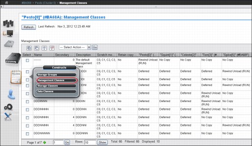
Figure 8-175 Management Classes
The Management Classes table (Figure 8-175) displays defined Management Class copy policies that can be applied to a cluster. You can use the Management Classes table to create a new Management Class, modify an existing Management Class, and delete one or more existing Management Classes. The default Management Class can be modified, but cannot be deleted. The default name of the Management Class uses eight dashes (--------).
The following status information is displayed in the Management Classes table:
•Name: The name of the Management Class
Valid characters for this field are A - Z, 0 - 9, $, @, *, #, and %. The first character of this field cannot be a number. This is the only field that cannot be modified after it is added.
•Secondary Pool: The target pool in the volume duplication
If the cluster does not possess a physical library, this column is not visible, and the MI categorizes the newly created Storage Groups using pool 0.
•Description: A description of the Management Class definition
The value in this field must be 1 - 70 characters in length.
•Scratch Mount Candidate
The cluster or clusters that are the candidates for scratch mounts. Clusters displayed in this field are selected first for scratch mounts of the volumes associated with the Management Class. If no clusters are displayed, the scratch mount process remains a random selection routine that includes all available clusters. For more information, see “Defining scratch mount candidates” on page 543.
•Retain Copy Mode (Yes or No)
Retain Copy mode accepts the original Copy Consistency Policy that is in place in the cluster where the volume was created. This mode prevents unwanted copies from being created throughout the grid. For more information, see Chapter 2, “Architecture, components, and functional characteristics” on page 13.
The Cluster Copy Policy enables you to define where and when copies are made.
Use the menu in the Management Classes table to add, modify, or delete Management Classes.
To add a Management Class, select Add from the menu and click Go. Complete the fields for information that you want displayed in the Management Classes table. You can create up to 256 Management Classes per TS7700 Virtualization Engine Grid.
|
Tip: If cluster is not attached to a physical library, the Secondary Pool field is not available in the Add option.
|
The Copy Action menu is next to each cluster in the TS7700 Virtualization Engine Grid. Use the Copy Action menu to select, for each component, the copy mode to use in volume duplication. The following actions are available from this menu:
•No Copy: No volume duplication occurs if this action is selected.
•Rewind Unload (RUN): Volume duplication occurs when the Rewind Unload command is received. The command returns only after the volume duplication completes successfully.
•Deferred: Volume duplication occurs later based on the internal schedule of the copy engine.
•Synchronous Copy: Provides tape copy capabilities up to synchronous-level granularity across two clusters within a multicluster grid configuration. For more information about Synchronous mode copy settings and considerations, see “Synchronous mode copy” on page 77.
•Time Delayed: Volume duplication will only occur after the delay time specified by the user elapses. This option is only available if all clusters in the grid are running R3.1 or higher level of code.
See “Management Classes window” on page 406 in this chapter for more information about this topic.
Storage Classes
By using the Storage Class construct, you can influence when a logical volume is removed from cache, and assign Cache Partition Residency for logical volumes in a TS7720T cluster.
A default Storage Class is always available. It is identified by eight dashes (--------) and cannot be deleted. Use the window shown in Figure 8-176 to define, modify, or delete a storage class used by the TS7700 Virtualization Engine to automate storage management through the classification of data sets and objects.

Figure 8-176 Storage Classes window on a TS7700
The Storage Classes table displays defined storage classes available to control data sets and objects within a cluster. Although storage classes are visible from all TS7700 clusters, only those clusters attached to a physical library can alter TVC preferences. A stand-alone TS7700 cluster that does not possess a physical library does not remove logical volumes from the tape cache, so the TVC preference for those clusters (disk only) is always Preference Level 1.
Use the Storage Classes table to create a storage class, or modify or delete an existing storage class. The default storage class can be modified, but cannot be deleted. The default storage class uses eight dashes as the name (--------).
The following status information is displayed in the Storage Classes table:
•Name: The name of the storage class.
Valid characters for this field are A - Z, 0 - 9, $, @, *, #, and %. The first character of this field might not be a number. The value in this field must be 1 - 8 characters in length.
•Tape Volume Cache Preference: The preference level for the storage class.
This setting determines how soon volumes are removed from cache after their copy to tape. This information can be modified only if the selected cluster possesses a physical library. If the selected cluster is a TS7720 Virtualization Engine (disk-only), volumes in that cluster’s cache display a Level 1 preference. The following values are valid:
– Use IART
Volumes are removed according to the Initial Access Response Time (IART) of the TS7700 Virtualization Engine.
– Level 0
Volumes are removed from the TVC as soon as they are copied to tape.
– Level 1
Copied volumes remain in the TVC until more space is required. Then, they are the first volumes removed to free space in the cache. This is the default preference level that is assigned to new preference groups.
•Volume Copy Retention Group: The name of the group that defines the preferred Auto Removal policy applicable to the logical volume.
The Volume Copy Retention Group provides more options to remove data from a TS7720 Virtualization Engine (disk-only) and for data in Cache Partition 0 (CP0) in a TS7720T, as the active data reaches full capacity. Volumes become candidates for removal if an appropriate number of copies exist on peer clusters and the volume copy retention time has elapsed since the volume was last accessed.
Volumes in each group are removed in order based on their least recently used (LRU) access times. The volume copy retention time describes the number of hours that a volume remains in cache before becoming a candidate for removal.
This field is displayed only if the cluster is a disk-only cluster that is part of a grid. A hybrid grid combines TS7700 clusters that both attach (TS7740 or TS7720T) and do not attach (TS7720) to a physical library. If the logical volume is in a scratch (Fast Ready) category and is on a disk-only cluster, retention settings no longer apply to the volume, which becomes a top priority candidate for removal. In this instance, the value displayed for the Volume Copy Retention Group is accompanied by a warning icon.
The following list describes the group types:
– Prefer Remove
Removal candidates in this group are removed after scratch-volume candidates have been exhausted.
– Prefer Keep
Removal candidates in this group are removed after removal of candidates in the Prefer Remove group.
– Pinned
Copies of volumes in this group are never removed from the accessing cluster. The volume copy retention time does not apply to volumes in this group. Subsequently, volumes in this group that are moved to scratch become priority candidates for removal.
|
Important: Care must be taken when assigning volumes to this group to avoid cache overruns.
|
•Volume Copy Retention Time: The minimum amount of time (in hours) after a logical volume copy was last accessed that the copy can be removed from cache.
The copy is said to be expired after this time has passed. The copy then becomes a candidate for removal. Possible values include any values in the range of 0 - 65,536. The default is 0.
If the Volume Copy Retention Group has a value of Pinned, this field is disabled.
•Description: A description of the storage class definition.
The value in this field must be 1 - 70 characters in length.
Use the menu in the Storage Classes table to add a storage class, or modify or delete an existing storage class.
To add a storage class, select Add from the menu. Complete the fields for the information that are displayed in the Storage Classes table. You can create up to 256 storage classes per TS7700 Virtualization Engine Grid.
To modify an existing storage class, click the radio button from the Select column that appears in the same row as the storage class that you want to modify. Select Modify from the menu. Of the fields listed in the Storage Classes table, you can change all of them except for the storage class name.
To delete an existing storage class, click the radio button from the Select column that appears in the same row as the storage class that you want to delete. Select Delete from the menu. A dialog box opens where you confirm the storage class deletion. Select Yes to delete the storage class, or select No to cancel the delete request.
|
Important: Do not delete any existing storage class if there are still logical volumes assigned to this storage class.
|
See “Storage Classes window” on page 409 in this chapter for more details about this topic.
Data Classes
From a z/OS perspective (SMS-managed tape), the DFSMS Data Class defines the following information:
•Media type parameters
•Recording technology parameters
•Compaction parameters
For the TS7700 Virtualization Engine, only the Media type, Recording technology, and Compaction parameters are used. The use of larger logical volume sizes is controlled through Data Class. A default Data Class is always available. It is identified by eight dashes (--------) and cannot be deleted.
Use the window shown in Figure 8-177 to define, modify, or delete a TS7700 Virtualization Engine Data Class. The Data Class is used to automate storage management through the classification of data sets.

Figure 8-177 Data Classes window
The Data Classes table (Figure 8-177) displays the list of Data Classes defined for each cluster of the grid.
You can use the Data Classes table to create a Data Class, or modify or delete an existing Data Class. The default Data Class can be modified, but cannot be deleted. The default Data Class shows the name as eight dashes (--------).
The following status information is displayed in the Data Classes table:
•Name: The name of the Data Class
Valid characters for this field are A - Z, 0 - 9, $, @, *, #, and %. The first character of this field cannot be a number. The value in this field must be 1 - 8 characters in length.
•Virtual Volume Size (mebibytes, MiB): The logical volume size of the Data Class
This setting determines the maximum number of MiB for each logical volume in a defined class. The following values are valid:
Insert Media Class Logical volume size is not defined, so the Data Class is not defined by a maximum logical volume size. You can use 1,000 MiB, 2,000 MiB, 4,000 MiB, 6,000 MiB, or 25,000 MiB.
|
Rules: Support for 25,000 MiB logical volumes is allowed without any restriction if all TS7700 clusters in grid operate at R3.2 of LIC level.
25000 MiB is not supported in mixed code-level grids (members not exclusively at R3.2) with one or more TS7740 cluster present in grid.
For disk-only grids (no tape-attached member) Feature Code 0001 is required in each TS7720 operating at levels earlier than R3.2 LIC.
|
•Logical Write Once Read Many (WORM)
It specifies whether logical WORM (LWORM) is set for the Data Class. LWORM is the virtual equivalent of WORM tape media, achieved through software emulation.
The following values are valid for this field:
– Yes
LWORM is set for the Data Class. Volumes belonging to the Data Class are defined as LWORM.
– No
LWORM is not set. Volumes belonging to the Data Class are not defined as LWORM. This is the default value for a new Data Class.
•Description: A description of the Data Class definition
The value in this field must be 0 - 70 characters in length.
Use the menu on the Data Classes table to add a Data Class, or modify or delete an existing Data Class. Figure 8-178 shows the Add Data Class window.

Figure 8-178 Add Data Class window
To add a Data Class, complete the following steps:
1. Select Add from the menu, and click Go.
2. Complete the fields for the information that displays in the Data Classes table.
|
Tip: You can create up to 256 Data Classes per TS7700 Virtualization Engine Grid.
|
To modify an existing Data Class, complete the following steps:
1. Select the check box in the Select column that appears in the same row as the Data Class that you want to modify.
2. Select Modify from the menu and click Go. Of the fields listed in the Data Classes table, you can change all of them except the default Data Class name.
To delete an existing Data Class, complete the following steps:
1. Click the radio button from the Select column that appears in the same row as the Data Class you want to delete.
2. Select Delete from the menu and click Go. A dialog box opens where you can confirm the Data Class deletion. Select Yes to delete the Data Class, or select No to cancel the delete request.
|
Important: Do not delete any existing Data Class if there are still logical volumes assigned to this Data Class.
|
Activating TS7700 license key for a new Feature Code
This section describes how to view information about, activate, or remove the following feature licenses from the TS7700 Virtualization Engine cluster:
•Peak data throughput increments
•Logical volume increments
•Cache enablement
•Grid enablement
•Selective Device Access Control enablement
•Encryption configuration enablement
•Dual port grid connection enablement
•Specific RPQ enablement
•Maximum amount of queued premigration content
|
Clarification: Cache enablement license key (FC5267) applies only to a TS7740 cluster, where Maximum amount of queued premigration content (FC5274) only applies to TS7720T tape attach configuration.
|
The amount of disk cache capacity and performance capability are enabled using feature license keys. You receive feature license keys for the features that you have ordered. Each feature increment enables you to tailor the subsystem to meet your disk cache and performance needs.
Use the Feature Licenses window (Figure 8-179) to activate feature licenses in the TS7700 Virtualization Engine. To open the window, complete the following steps:
1. Select Activate New Feature License from the list and click Go.
2. Enter the license key into the fields provided and select Activate.

Figure 8-179 Feature Licenses window
To remove a license key, complete the following steps:
1. Select the feature license to be removed.
2. Select Remove Selected Feature License from the list, and click Go.
|
Important: Do not remove any installed peak data throughput features, because removal can affect host jobs.
Some feature codes are not removable after being installed.
|
When you select Activate New Feature License, the Feature License entry window opens, as shown in Figure 8-180. When you enter a valid feature license key and click Activate, the feature is activated.
|
Tip: Performance Increments become active immediately. Others, such as Cache Increments or FICON dual port enablement, take 10 - 30 minutes to become active.
|

Figure 8-180 Activate New Feature Licenses window
Defining Simple Network Management Protocol
Use the window shown in Figure 8-181 to view or modify the Simple Network Management Protocol (SNMP) configured on an IBM TS7700 Virtualization Engine Cluster.
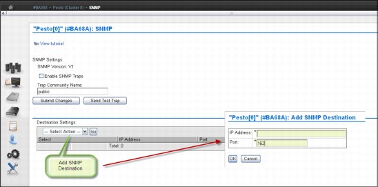
Figure 8-181 SNMP settings
Use the window to configure SNMP traps that will log operation history events, such as login occurrences, configuration changes, status changes (vary on or off and service prep), shut down, and code updates. SNMP is a networking protocol that enables an IBM TS7700 Virtualization Engine to automatically gather and transmit information about alerts and status to other entities in the network.
SNMP Settings section
This section provides information about configuring global settings that apply to SNMP traps on an entire cluster. You can configure the following settings:
•SNMP Version: The SNMP version defines the protocol used in sending SNMP requests and is determined by the tool you are using to monitor SNMP traps. Different versions of SNMP traps work with different management applications. The only possible value on TS7700 Virtualization Engine is V1. No alternative version is supported.
•Enable SMP Traps: This check box enables or disables SNMP traps on a cluster. If the check box is selected, SNMP traps on the cluster are enabled. If the check box is not selected (the default), SNMP traps on the cluster are disabled.
•Trap Community Name: This name identifies the trap community and is sent along with the trap to the management application. This value behaves as a password. The management application does not process an SNMP trap unless it is associated with the correct community. This value must be 1 - 15 characters in length and consists of Unicode characters.
•Send Test Trap: This button sends a test SNMP trap to all destinations listed in the Destination Settings table using the current SNMP trap values. The Enable SNMP Traps check box does not need to be checked to send a test trap. If the SNMP test trap is received successfully and the information is correct, select Submit Changes.
•Submit Changes: Select this button to submit changes to any of the global settings, including the SNMP Version, Enable SNMP Traps, and Trap Community Name fields.
Destination Settings section
Use the Destination Settings table to add, modify, or delete a destination for SNMP trap logs. You can add, modify, or delete a maximum of 16 destination settings at one time. You can configure the following settings:
•IP Address: The IP address of the SNMP server. This value can take any of the following formats: IPv4, IPv6, a host name resolved by the system (such as localhost), or a fully qualified domain name (FQDN) if a domain name server (DNS) is provided. A value in this field is required.
A valid IPv4 address is 32 bits, consists of four decimal numbers, each 0 - 255, separated by periods, for example:
98.104.120.12
A valid IPv6 address is a 128-bit hexadecimal value separated into 16-bit fields by colons, for example:
3afa:1910:2535:3:110:e8ef:ef41:91cf
Leading zeros can be omitted in each field, so that :0003: can be written as :3:. A double colon (::) can be used once per address to replace multiple fields of zeros, for example:
3afa:0:0:0:200:2535:e8ef:91cf
can be written this way:
3afa::200:2535:e8ef:91cf
A fully qualified host name is a domain name that uniquely and absolutely names a computer. It consists of the host name and the domain name. The domain name is one or more domain labels that place the computer in the DNS naming hierarchy. The host name and the domain name labels are separated by periods, and the total length of the host name cannot exceed 255 characters.
•Port: This port is where the SNMP trap logs are sent. This value must be a number
0 - 65535. A value in this field is required.
0 - 65535. A value in this field is required.
|
Restriction: A user with read-only permissions cannot modify the contents of the Destination Settings table.
|
Use the Select Action menu in the Destination Settings table to add, modify, or delete an SNMP trap destination. Destinations are changed in the vital product data (VPD) as soon as they are added, modified, or deleted. These updates do not depend on your selecting Submit Changes on the window:
•Add SNMP destination: Select this menu item to add an SNMP trap destination for use in the IBM TS7700 Virtualization Engine Grid.
•Modify SNMP destination: Select this menu item to modify an SNMP trap destination that is used in the IBM TS7700 Virtualization Engine Grid.
•Confirm delete SNMP destination: Select this menu item to delete an SNMP trap destination used in the IBM TS7700 Virtualization Engine Grid.
Enabling IPv6
IPv6 and Internet Protocol Security (IPSec) are supported beginning with release 3.0 of Licensed Internal Code by the 3957-V07 and 3957-VEB configurations of the TS7700 Virtualization Engine.
|
Tip: The client network must use whether IPv4 or IPv6 for all functions, such as MI, key manager server, SNMP, Lightweight Directory Access Protocol (LDAP), and Network Time Protocol (NTP). Mixing IPv4 and IPv6 is not currently supported.
|
Figure 8-182 shows how to enable IPv6 in a TS7700 Virtualization Engine.
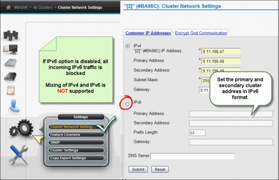
Figure 8-182 Configuring IPv6
For more information about IPv6, see “IPv6 support” on page 128 and Figure 8-120 on page 440.
Enabling IPSec
Beginning with Release 3.0 of Licensed Internal Code, the 3957-V07 and 3957-VEB configurations of the TS7700 Virtualization Engine support IPSec over the grid links.
|
Caution: Enabling grid encryption significantly affects the performance of the TS7700 Virtualization Engine.
|
Figure 8-183 shows how to enable the IPSec for the TS7700 cluster.

Figure 8-183 Enabling IPSec in the grid links
In a multicluster grid, the user can choose which link is encrypted by selecting the box in front of the beginning and ending cluster for the selected link. Figure 8-183 depicts a two-cluster grid, which is the reason why there is only one option to select.
For more information about IPSec, see “IPSec support for the grid links” on page 128. Also, see the IBM TS7700 Virtualization Engine IBM Knowledge Center at:
Defining Security Settings
Use this section to set up and check the security settings for the TS7700 Virtualization Engine grid. From this page in the MI, you can perform these functions:
•Add a policy
•Modify an existing policy
•Assign an authentication policy
•Test the security setting before running the application
•Delete an existing policy
Each cluster in your configuration can have a different security policy assigned to it. However, only one policy can be in effect on a cluster at a time.
Figure 8-184 shows the Security Settings window.

Figure 8-184 Security settings
For Session Timeout, you specify the number of hours and minutes that the MI can be idle before the current session expires and the user is redirected to the login page.
The Authentication Policies table shows the defined policies in the TS7700 Virtualization Engine Grid. You can set these policies:
•Local: This means that users and their assigned roles are replicated throughout the grid.
•External: This policy stores user and group data on a separate server, verifying the relationship between users, groups, and authorization roles whenever a user logs in to a cluster.
Direct LDAP and Storage Authentication Service policies are included in the external policies.
|
Important: When a Storage Authentication Service policy is enabled for a cluster, service personnel are required to log in with the setup user or group. Be sure that an account has been created for the service personnel before enabling storage authentication.
|
Storage Authentication Service Policy
The Storage Authentication Service Policy uses a centrally managed role-based access control policy (RBAC) that authenticates and authorizes users by using the System Storage Productivity Center to authenticate users to an LDAP server.
Figure 8-185 shows the Add Storage Authentication Service Policy window.

Figure 8-185 Add Storage Authentication Service Policy
Direct LDAP Policy
Figure 8-186 shows the Add Direct LDAP Policy menu. Use this menu to add an RBAC policy that authenticates and authorizes users through direct communication with an LDAP server.
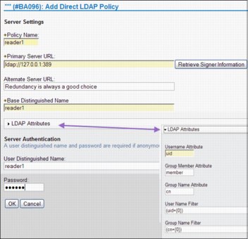
Figure 8-186 Add Direct LDAP Policy
|
Important: When a Storage Authentication Service policy is enabled for a cluster, service personnel are required to log in with the setup user or group. Be sure that an account has been created for the service personnel before enabling storage authentication.
|
The fields in both Figure 8-186 on page 537 and Figure 8-185 on page 537 are defined in the following list:
•Policy Name: The name of the policy that defines the authentication settings. The policy name is a unique value that consists of one to 50 Unicode characters. Heading and trailing blank spaces are deleted, but internal blank spaces are retained. The name of the Local policy is Local. Authentication policy names, either Local or user-created, cannot be modified after they are created.
•Primary Server URL: The primary URL for the Storage Authentication Service1. The value in this field consists of 1 - 254 Unicode characters and takes one of the following formats:
– https://<server_address>:secure_port/TokenService/services/Trust
– ldaps://<server_address>:secure_port
– ldap://<server_address>:port
If a domain name server (DNS) address needs to be used here, a DNS must be activated and configured on the Cluster Network settings page. See 8.2.10, “The Settings icon” on page 441.
•Alternative Server URL: The alternative URL for the Storage Authentication Service if the primary URL cannot be accessed. The value is the same as the value described in the previous item.1
•Server Authentication: Values are required in the user ID and password fields if IBM WebSphere Application Server security is enabled on the WebSphere Application Server hosting the Authentication Service, or if anonymous access is disabled on the LDAP server:
– User ID: The user name used with HTTP basic authentication for authenticating to the Storage Authentication Service. Maximum length of 254 Unicode characters.
– Password: The password used with HTTP basic authentication for authenticating to the Storage Authentication Service. Maximum length of 254 Unicode characters.
•Direct LDAP: Values in the following fields are required if secure authentication is used or anonymous connections are disabled in the LDAP server:
– User Distinguished Name: Used to authenticate to the LDAP authentication service. Maximum length of 254 Unicode characters, for example: CN=Administrator,CN=users,DC=mycompany,DC=com
– Password: The password to authenticate to the LDAP authentication service. Maximum length of 254 Unicode characters.
– Base Distinguished Name: The distinguished name (DN) uniquely identifies a set of entries in a domain. Maximum length of 254 Unicode characters.
– User name Attribute: The attribute name used for the user name during authentication. This field is required and contains the value uid, by default. Maximum length of 61 Unicode characters.
– Password Attribute: The attribute name used for the password during authentication. This field is required and contains the value userPassword, by default. Maximum length of 61 Unicode characters.
– Group Member Attribute: The attribute name used to identify the group during authorization. This field is optional and contains the value member, by default. Maximum length of 61 Unicode characters.
– Group Name Attribute: The attribute name used to identify the group during authorization. This field is optional and contains the value cn, by default. Maximum length of 61 Unicode characters.
– User name filter: Used to filter and validate an entered user name. This field is optional and contains the value (uid={0}), by default. Maximum length of 254 Unicode characters.
– Group Name filter: Used to filter and validate an entered group name. This field is optional and contains the value (cn={0}), by default. Maximum length of 254 Unicode characters.
RACF based LDAP Policy
RACF based LDAP is a particular case of Direct LDAP policy. The procedure is similar to the previous topic, only there are some configurations on the host side regarding the RACF, SDBM, and Tivoli LDAP server that must be in place before defining the RACF based LDAP policy in the Management Interface. See “Creating a RACF-based LDAP Policy” on page 434 in this chapter for more details.
Local policy
The Local policy is the default authentication policy. When enabled, it is in effect for all clusters on the grid. It is mutually exclusive with the Storage Authentication Service. Local policy can be modified to add, change, or delete individual accounts, but the policy itself cannot be deleted.
Figure 8-187 shows the Modify Local Policy window.

Figure 8-187 Modify Local Accounts
Use this window to modify the Local policy settings for the TS7700 Virtualization grid. You can define the following information:
•Whether accounts defined by a policy can expire, and if so, the number of days that a password can be used before it expires. Possible values are 1 - 999.
•Whether accounts defined by a policy can be locked after several successive incorrect password retries (1 - 9).
8.3.4 TS7700 Virtualization Engine multicluster definitions
The following sections describe TS7700 multicluster definitions.
Defining grid copy mode control
When upgrading a stand-alone cluster to a grid, FC4015, Grid Enablement, must be installed on all clusters in the grid. Also, you must set up the Copy Consistency Points in the Management Class definitions on all clusters in the new grid.
The data consistency point is defined in the Management Classes construct definition through the MI. You can perform this task only for an existing grid system. In a stand-alone cluster configuration, you see only your stand-alone cluster in the Modify Management Class definition.
To open the Management Classes window, complete the following steps:
1. Click Constructs → Management Classes under the Welcome Admin menu.
2. Select the Management Class name and select Modify from the Select Action menu.
3. The next window (Figure 8-188) is where you can modify the copy consistency by using the Copy Action table, and then clicking OK. In this example, the TS7700 Virtualization Engine (named Pesto) is part of a multicluster grid configuration. This additional menu is displayed only if a TS7700 Virtualization Engine is part of a multicluster grid environment.

Figure 8-188 Modify Management Classes
As shown in Figure 8-188, you can choose between three consistency points per cluster:
•No Copy: No copy (NC) is made to this cluster.
•Rewind Unload (RUN): A valid version of the logical volume has been copied to this cluster as part of the volume unload processing.
•Deferred: A replication of the modified logical volume is made to this cluster after the volume had been unloaded (DEF).
•Synchronous copy: Provides tape copy capabilities up to synchronous-level granularity across two clusters within a multicluster grid configuration.
•Time Delayed: Volume copy occurs after the specified delay time period passes. This option is implemented by R3.1 of the Licensed Internal Code. Options are:
– Delay Queuing Copies for [X] hours, where X is a number from 1 - 65,353.
– Start Delay after one of these triggers:
• The time of the creation of the volume
• The time where the last access to that volume occurred
•No Copy: No copy is necessary for that cluster.
|
Tip: A stand-alone grid (stand-alone TS7700 Virtualization Engine) always uses Rewind Unload (RUN) as the Data Consistency Point.
|
Also, check the following links for detailed information about this subject:
•IBM Virtualization Engine TS7700 Series Best Practices - TS7700 Hybrid Grid Usage:
•IBM Virtualization Engine TS7700 Series Best Practices - Copy Consistency Points:
•IBM Virtualization Engine TS7700 Series Best Practices - Synchronous Mode Copy:
Define Copy Policy Override settings
With the TS7700 Virtualization Engine, you can define and set the optional override settings that influence the selection of the I/O TVC and replication responses. The settings are specific to a cluster in a multicluster grid configuration, which means that each cluster can have separate settings, if you want. The settings take effect for any mount requests received after the settings were saved. Mounts already in progress are not affected by a change in the settings. You can define and set the following settings:
•Prefer local cache for scratch (Fast Ready) mount requests
•Prefer local cache for private (non-Fast Ready) mount requests
•Force volumes mounted on this cluster to be copied to the local cache
•Enable fewer RUN consistent copies before reporting RUN command complete
•Ignore cache preference groups for copy priority
You can view and modify these settings from the TS7700 Virtualization Engine MI by clicking Settings → Cluster Setting → Copy Policy Override, as shown in Figure 8-189.
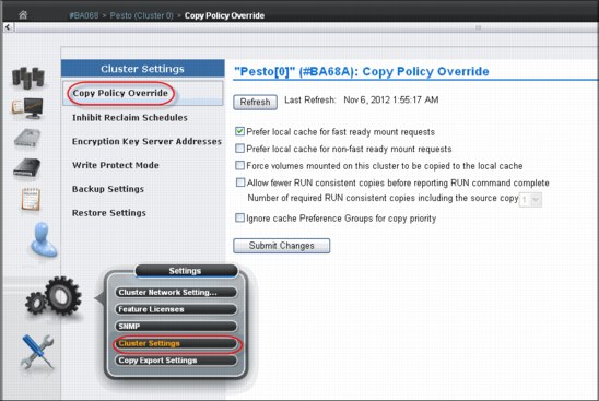
Figure 8-189 Cluster Settings
You can select the following settings in the MI window:
•Prefer local cache for Fast Ready mount requests
A scratch (Fast Ready) mount selects a local copy if a cluster Copy Consistency Point is not specified as No Copy in the Management Class for the mount. The cluster is not required to have a valid copy of the data.
•Prefer local cache for private (non-Fast Ready) mount requests
This override causes the local cluster to satisfy the mount request if the cluster is available and the cluster has a valid copy of the data, even if that data is only resident on physical tape. If the local cluster does not have a valid copy of the data, the default cluster selection criteria applies.
•Force volumes mounted on this cluster to be copied to the local cache
For a private (non-Fast Ready) mount, this override causes a copy to be run on the local cluster as part of mount processing. For a scratch (Fast Ready) mount, this setting overrides the specified Management Class with a Copy Consistency Point of Rewind-Unload for the cluster. This does not change the definition of the Management Class, but influences the Replication policy.
•Enable fewer RUN consistent copies before reporting RUN command complete
If selected, the value entered for Number of required RUN consistent copies including the source copy is used to determine the number of copies to override before the Rewind Unload operation reports as complete. If this option is not selected, the Management Class definitions are used explicitly. Therefore, the number of RUN copies can be from one to the number of clusters in the grid.
•Ignore cache preference groups for copy priority
If this option is selected, copy operations ignore the cache preference group when determining the priority of volumes copied to other clusters.
|
Restriction: In a Geographically Dispersed Parallel Sysplex (GDPS), all three Copy Policy Override settings (cluster overrides for certain I/O and copy operations) must be selected on each cluster to ensure that wherever the GDPS primary site is, this TS7700 Virtualization Engine cluster is preferred for all I/O operations.
If the TS7700 Virtualization Engine cluster of the GDPS primary site fails, you must complete the following recovery actions:
1. Vary virtual devices from a remote TS7700 Virtualization Engine cluster online from the primary site of the GDPS host.
2. Manually start, through the TS7700 Virtualization Engine MI, a read/write Ownership Takeover, unless Autonomic Ownership Takeover Manager (AOTM) has already transferred ownership.
|
Defining scratch mount candidates
Scratch allocation assistance (SAA) is an extension of the device allocation assistance (DAA) function for scratch mount requests. SAA filters the list of clusters in a grid to return to the host a smaller list of candidate clusters designated as scratch mount candidates.
If you have a grid with two or more clusters, you can define scratch mount candidates. For example, in a hybrid configuration, the SAA function can be used to direct certain scratch allocations (workloads) to one or more TS7720 Virtualization Engines for fast access. Other workloads can be directed to TS7740 or TS7720T Virtualization Engines for archival purposes.
Clusters not included in the list of scratch mount candidates are not used for scratch mounts at the associated Management Class unless those clusters are the only clusters known to be available and configured to the host.
See Chapter 9, “Host Console Operations” on page 567 for information regarding software levels required by SAA and DAA to function properly, in addition to the LI REQ commands that are related to the SAA and DAA operation.
As shown in Figure 8-190, by default all clusters are chosen as scratch mount candidates. Select which clusters are candidates by Management Class. If no clusters are checked, the TS7700 defaults to all clusters being candidates.
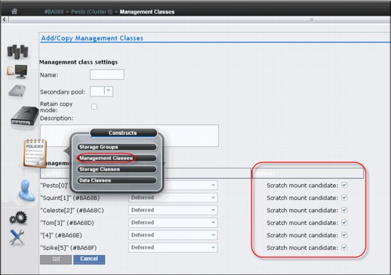
Figure 8-190 Scratch mount candidate list in Add Management Classes window
Each cluster in a grid can provide a unique list of candidate clusters. Clusters with an ‘N’ copy mode, such as cross-cluster mounts, can still be candidates.
|
Note: Scratch mount candidate list as defined in MI (Figure 8-190) is only accepted upon being enabled using the LI REQ setting.
|
Retain Copy mode
Retain Copy mode is an optional setting where a volume’s existing Copy Consistency Points are accepted rather than applying the Copy Consistency Points defined at the mounting cluster. This applies to private volume mounts for reads or write appends. It is used to prevent more copies of a volume being created in the grid than wanted. This is important in a grid with three or more clusters that has two or more clusters online to a host.
This parameter is set in the Management Classes window for each Management Class when you add a Management Class. Figure 8-191 shows the Management Classes window and the Retain Copy mode check box.
|
Note: The Retain Copy mode option is effective only on private (non-Fast Ready) virtual volume mounts.
|
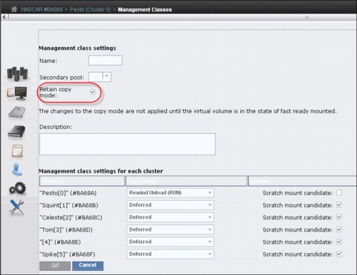
Figure 8-191 Retain Copy mode selection in the Management Classes window
Defining cluster families
If you have a grid with three or more clusters, you can define cluster families.
This function introduces a concept of grouping clusters together into families. Using cluster families, you can define a common purpose or role to a subset of clusters within a grid configuration. The role assigned, for example, production or archive, is used by the TS7700 microcode to make improved decisions for tasks, such as replication and TVC selection. For example, clusters in a common family are favored for TVC selection, or replication can source volumes from other clusters within its family before using clusters outside of its family.
Use the Cluster Families option on the Actions menu of the Grid Summary window to add, modify, or delete a cluster family. Figure 8-192 shows the menu for the cluster families.
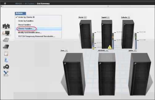
Figure 8-192 Cluster Families menu option
To view or modify cluster family settings, complete the following steps:
1. First, verify that these permissions are granted to your assigned user role.
2. Then, select Cluster Families from the Actions menu to run the following actions:
Add a family
To add a family, complete the following steps:
1. Click Add to create a new cluster family. A new cluster family placeholder is created to the right of any existing cluster families.
2. Enter the name of the new cluster family in the active Name text box. Cluster family names must be 1 - 8 characters in length and consist of Unicode characters. Each family name must be unique.
3. To add a cluster to the new cluster family, move a cluster from the Unassigned Clusters area by following instructions in “Move a cluster” on page 547.
|
Restriction: A maximum of eight cluster families can be created.
|
Move a cluster
You can move one or more clusters between existing cluster families to a new cluster family from the Unassigned Clusters area, or to the Unassigned Clusters area from an existing cluster family:
1. Select a cluster: A selected cluster is identified by a highlighted border. Select a cluster from its resident cluster family or the Unassigned Clusters area with any of these methods:
– Clicking the cluster
– Pressing the Spacebar
– Pressing Shift while selecting clusters to select multiple clusters at one time
– Pressing Tab to switch between clusters before selecting a cluster
2. Move the selected cluster or clusters using one these methods:
– Clicking a cluster and dragging it to the destination cluster family or the Unassigned Clusters area
– Using the keyboard arrow keys to move the selected cluster or clusters right or left
Delete a family
You can delete an existing cluster family:
1. Click the X in the upper-right corner of the cluster family that you want to delete. If the cluster family that you attempt to delete contains any clusters, a warning message displays.
2. Click OK to delete the cluster family and return its clusters to the Unassigned Clusters area. Click Cancel to abandon the delete action and retain the selected cluster family.
Save changes
Click Save to save any changes made to the Cluster families page and return it to read-only mode.
|
Restriction: Each cluster family must contain at least one cluster. If you attempt to save changes and a cluster family does not contain any clusters, an error message is displayed and the Cluster families page remains in edit mode.
|
Cluster family configuration
Figure 8-193 illustrates the actions to create a family.

Figure 8-193 Creating a cluster family
Figure 8-194 shows an example of a cluster family configuration.
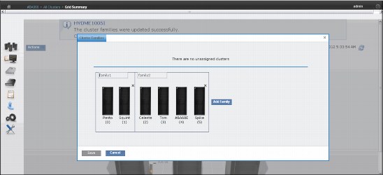
Figure 8-194 Cluster families
|
Important: Each cluster family needs to contain at least one cluster.
|
TS7720 cache thresholds and removal policies
This topic describes the boundaries (thresholds) of free cache space in a disk-only TS7720 or TS7720T CP0 partition cluster and the policies that can be used to manage available (active) cache capacity in a grid configuration.
Cache thresholds for a TS7720 and TS7720T resident partition (CP0)
A disk-only TS7720 and the resident partition (CP0) of a TS7720T (tape attach) configuration does not attach to a physical library. All virtual volumes are stored in the cache. Three thresholds define the active cache capacity in a TS7720 Virtualization Engine and determine the state of the cache as it relates to remaining free space. In ascending order of occurrence, these are the three thresholds:
•Automatic Removal
The policy removes the oldest logical volumes from the TS7720 cache if a consistent copy exists elsewhere in the grid. This state occurs when the cache is 4 TB below the out-of-cache-resources threshold. In the automatic removal state, the TS7720 Virtualization Engine automatically removes volumes from the disk-only cache to prevent the cache from reaching its maximum capacity. This state is identical to the limited-free-cache-space-warning state unless the Temporary Removal Threshold is enabled.
You can disable automatic removal within any specific TS7720 cluster by using the following library request command:
LIBRARY REQUEST,CACHE,REMOVE,{ENABLE|DISABLE}
So that a disaster recovery test can access all production host-written volumes, automatic removal is temporarily disabled while disaster recovery write protect is enabled on a disk-only cluster. When the write protect state is lifted, automatic removal returns to normal operation.
•Limited free cache space warning
This state occurs when there is less than 3 TB of free space left in the cache. After the cache passes this threshold and enters the limited-free-cache-space-warning state, write operations can use only an extra 2 TB before the out-of-cache-resources state is encountered. When a TS7720 cluster enters the limited-free-cache-space-warning state, it remains in this state until the amount of free space in the cache exceeds 3.5 TB. The following messages can be displayed on the MI during the limited-free-cache-space-warning state:
– HYDME0996W
– HYDME1200W
For more information, see the related information section in the TS7700 IBM Knowledge Center about each of these messages:
|
Clarification: Host writes to the TS7720 cluster and inbound copies continue during this state.
|
•Out of cache resources
This state occurs when there is less than 1 TB of free space left in the cache. After the cache passes this threshold and enters the out-of-cache-resources state, it remains in this state until the amount of free space in the cache exceeds 3.5 TB. When a TS7720 cluster is in the out-of-cache-resources state, volumes on that cluster become read-only and one or more out-of-cache-resources messages are displayed on the MI. The following messages can display:
– HYDME0997W
– HYDME1133W
– HYDME1201W
For more information, see the related information section in the TS7700 IBM Knowledge Center about each of these messages:
|
Clarification: New host allocations do not choose a TS7720 cluster in this state as a valid TVC candidate. New host allocations sent to a TS7720 cluster in this state choose a remote TVC instead. If all valid clusters are in this state or unable to accept mounts, the host allocations fail. Read mounts can choose the TS7720 cluster in this state, but modify and write operations fail. Copies inbound to this TS7720 cluster are queued as Deferred until the TS7720 cluster exits this state.
|
Table 8-15 displays the start and stop thresholds for each of the active cache capacity states defined.
Table 8-15 Active cache capacity state thresholds
|
State
|
Enter state (free space available)
|
Exit state (free space available)
|
Host message displayed
|
|
Automatic removal
|
< 4 TB
|
> 3.5 TB
|
CBR3750I when automatic removal begins
|
|
Limited free cache space warning
|
< 3 TB
|
> 3.5 TB
|
CBR3792E upon entering state
CBR3793I upon exiting state
|
|
Out of cache resources
|
< 1 TB
|
> 3.5 TB
|
CBR3794A upon entering state
CBR3795I upon exiting state
|
|
Temporary removal1
|
< (X = 1 TB)2
|
> (X + 1.5 TB)b
|
Console message
|
1 When enabled
2 Where X is the value set by the Tape Volume Cache window on the specific cluster.
The Removal policy is set by using the Storage Class window on the TS7720 MI. Figure 8-195 shows several definitions in place.
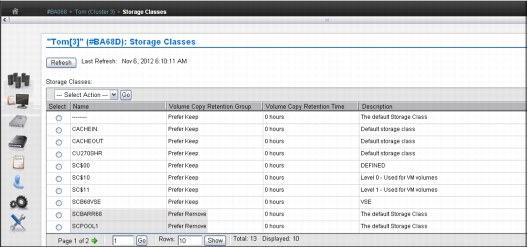
Figure 8-195 Storage Classes in TS7720 with removal policies
To add or change an existing Storage Class, select the appropriate action in the menu, and click Go. See Figure 8-196.

Figure 8-196 Defining a new Storage Class with TS7720
Removal Threshold
The Removal Threshold is used to prevent a cache overrun condition in a TS7720 cluster that is configured as part of a grid. By default, it is a 4 TB value (3 TB fixed, plus 1 TB) that, when taken with the amount of used cache, defines the upper limit of a TS7720 cache size. Above this threshold, logical volumes begin to be removed from a TS7720 cache.
|
Note: Logical volumes are only removed if there is another consistent copy within the grid.
|
Logical volumes are removed from a TS7720 cache in this order:
1. Volumes in scratch (Fast Ready) categories
2. Private volumes least recently used, using the enhanced Removal policy definitions
After removal begins, the TS7720 Virtualization Engine continues to remove logical volumes until the Stop Threshold is met. The Stop Threshold is the Removal Threshold minus 500 GB. A particular logical volume cannot be removed from a TS7720 cache until the TS7720 Virtualization Engine verifies that a consistent copy exists on a peer cluster. If a peer cluster is not available, or a volume copy has not yet completed, the logical volume is not a candidate for removal until the appropriate number of copies can be verified later.
|
Tip: This field is only visible if the selected cluster is a TS7720 Virtualization Engine in a grid configuration.
|
Temporary Removal Threshold
The Temporary Removal Threshold lowers the default Removal Threshold to a value lower than the Stop Threshold in anticipation of a service mode event. Logical volumes might need to be removed before one or more clusters enter service mode. When a cluster in the grid enters service mode, remaining clusters can lose their ability to make or validate volume copies, preventing the removal of enough logical volumes. This scenario can quickly lead to the TS7720 cache reaching its maximum capacity.
The lower threshold creates extra free cache space, which enables the TS7720 Virtualization Engine to accept any host requests or copies during the service outage without reaching its maximum cache capacity. The Temporary Removal Threshold value must be equal to or greater than the expected amount of compressed host workload written, copied, or both to the TS7720 Virtualization Engine during the service outage.
The default Temporary Removal Threshold is 4 TB, which provides 5 TB (4 TB plus 1 TB) of existing free space. You can lower the threshold to any value between 2 TB and full capacity minus 2 TB.
All TS7720 clusters in the grid that remain available automatically lower their Removal Thresholds to the Temporary Removal Threshold value defined for each. Each TS7720 cluster can use a different Temporary Removal Threshold. The default Temporary Removal Threshold value is 4 TB (an extra 1 TB more data than the default removal threshold of 3 TB).
Each TS7720 cluster uses its defined value until any cluster in the grid enters service mode or the temporary removal process is canceled. The cluster that is initiating the temporary removal process does not lower its own removal threshold during this process.
Removal policy settings can be configured by using the TS7720 Temporary Removal Threshold option on the Actions menu available on the Grid Summary page of the TS7700 Virtualization Engine MI. Figure 8-197 shows the TS7720 Temporary Removal Threshold mode window.
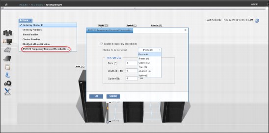
Figure 8-197 Setting Temporary Remove Threshold in a TS7720
The TS7720 Temporary Removal Threshold mode window includes these options:
•Enable Temporary Thresholds
Check this box and click OK to start the pre-removal process. Clear this box and click OK to abandon a current pre-removal process.
•Cluster to be serviced
Select from this menu the cluster that will be put into service mode. The pre-removal process is started on this cluster.
|
Note: This process does not initiate Service Prep mode.
|
If the cluster selected from this menu is a TS7720 cluster, it is disabled in the TS7720 List because the Temporary Removal Threshold will not be lowered on this cluster.
•TS7720 List
This area of the window contains each TS7720 cluster in the grid and a field to set the temporary removal threshold for that cluster.
8.4 Basic operations
The tasks that might be needed during the operation of a TS7700 Virtualization Engine are explained.
8.4.1 Clock and time setting
The TS7700 Virtualization Engine time can be set from a Network Time Protocol (NTP) server or by the IBM SSR. It is set to Coordinated Universal Time. See “Data and Time coordination” on page 57 for more details about time coordination.
|
Note: Unless you have a strong reason not to, use Coordinated Universal Time in all TS7700 clusters.
|
The TS3500 Tape Library time can be set from IBM Ultra Scalable Specialist work items by selecting Library → Date and Time as shown in Figure 8-198.

Figure 8-198 TS3500 Tape Library Specialist Date and Time
8.4.2 Library in Pause mode
During the operation, the TS3500 (the physical tape library) can enter in pause mode, and this might affect the related TS7740 or TS7720T, regardless of being in a grid or not. The reasons for the pause can include an enclosure door that is being opened to clear a device after a load/unload failure or to remove cartridges from the high capacity I/O station. The following message is displayed at the host when a library is in Pause or manual mode:
CBR3757E Library library-name in {paused | manual mode} operational state
During Pause mode, all recalls and physical mounts are held up and queued by the TS7740 or TS7720T Virtualization Engine for later processing when the library leaves the Pause mode. Because both scratch mounts and private mounts with data in the cache are allowed to run, but not physical mounts, no more data can be moved out of the cache after the currently mounted stacked volumes are filled.
The cache is filling up with data that has not been copied to stacked volumes. This results in significant throttling and finally in the stopping of any mount activity in the TS7740 cluster or in the tape partitions in the TS7720T cluster. For this reason, it is important to minimize the amount of time that is spent with the library in Pause mode.
8.4.3 Preparing a TS7700 Virtualization Engine for service
When an operational TS7700 Virtualization Engine needs to be taken offline for service, the TS7700 Virtualization Engine Grid must first be prepared for the loss of the resources involved to provide continued access to data. The controls to prepare a TS7700 Virtualization Engine for service (Service Prep) are provided through the MI. This menu is described in “Service mode window” on page 314.
Here is the message posted to all hosts when the TS7700 Virtualization Engine Grid is in this state:
CBR3788E Service preparation occurring in library library-name.
More details about service preparation are in Chapter 2, “Architecture, components, and functional characteristics” on page 13.
|
Tip: Before starting service preparation at the TS7700 Virtualization Engine, all virtual devices on this cluster must be in offline state to the accessing hosts. Pending offline devices (logical volumes mounted to local or remote TVC) with active tasks should be allowed to finish execution and volumes to unload, completing transition to offline state.
Virtual devices in other clusters should be made online to provide mount point to new jobs, shifting workload to other clusters in the grid before start service preparation. After scheduled maintenance finishes and TS7700 can be taken out of service, then virtual devices can be varied back online for accessing hosts.
|
Preparing the tape library for service
If the TS3500 Tape Library in a TS7700 Virtualization Engine Grid needs to be serviced, the effect over the associated cluster needs to be evaluated, and the decision about whether to bring associated cluster (TS7740 or TS7720T) into service or not should be taken. It depends on the duration of the planned outage for the TS3500, the role played by the tape attached cluster or partition in this particular grid architecture, the policies in force within this grid, and so on.
There might be cases where the best option is to prepare the cluster (TS7740 or TS7720T) for service before service the TS3500. In addition, there might be other scenarios where the best option is to service the TS3500 without bringing the associated cluster in service.
Work with your IBM Service Representative to identify which option is best in your specific case.
See “Cluster Actions menu” on page 311 for information about how to set the TS7700 Virtualization Engine in service preparation mode.
8.4.4 TS3500 Tape Library inventory
Use this window (Figure 8-199) from the TS3500 Tape Library Specialist to run Inventory/Audit.
You can choose All Frames or a selected frame from the menu.

Figure 8-199 TS3500 Tape Library inventory
After you click the Inventory/Audit tab, you receive the message shown in Figure 8-200.
|
Note: Perform Inventory if there is no high-density frame installed on the tape library. Perform Inventory will inventory high-density frame cells only for the first cartridge unless the first cartridge differs from the stored library inventory. Perform Inventory with Audit will inventory all cells in a high-density frame.
|
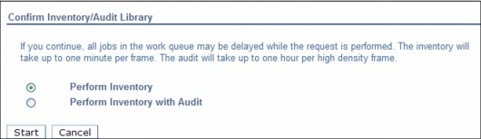
Figure 8-200 TS3500 Tape Library inventory message
|
Important: As stated on the confirmation window (Figure 8-200), if you continue, all jobs in the work queue might be delayed while the request is run. The inventory takes up to 1 minute per frame. The audit takes up to 1 hour per high-density frame.
|
8.4.5 Inventory upload
See the “Physical Volume Ranges” on page 390 for information about an inventory upload. See also Figure 8-82 on page 390.
Click Inventory Upload to synchronize the physical cartridge inventory from the attached tape library with the TS7740 or TS7720T Virtualization Engine database.
|
Note: Perform the Inventory Upload from the TS3500 Tape Library to all TS7740 or TS7720T Virtualization Engines attached to that tape library whenever a library door is closed, manual inventory or Inventory with Audit is run, or TS7700 cluster is varied online from an offline state.
|
8.5 Tape cartridge management
Most of the tape management operations are described in 8.1, “User interfaces” on page 290. This section provides information about tape cartridges and labels, inserting and ejecting stacked volumes.
8.5.1 3592 tape cartridges and labels
The data tape cartridge that is used in a 3592 contains the following items (numbers correspond to Figure 8-201):
•A single reel of magnetic tape
•Leader pin (1)
•Clutch mechanism (2)
•Cartridge write-protect mechanism (3)
•Internal cartridge memory (CM)
Figure 8-201 shows a J-type data cartridge.
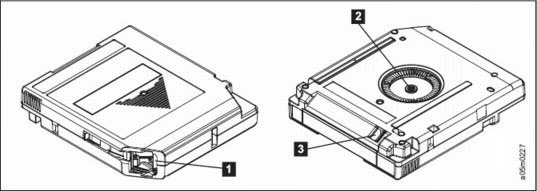
Figure 8-201 Tape cartridge
See Table 4-6 on page 120 and Table 4-7 on page 121 for a complete list of drives, models, and compatible cartridge types.
Labels
The cartridges use a media label to describe the cartridge type, as shown in Figure 8-202 (JA example). In tape libraries, the library vision system identifies the types of cartridges during an inventory operation. The vision system reads a volume serial number (VOLSER), which appears on the label on the edge of the cartridge. The VOLSER contains 1 - 6 characters, which are left-aligned on the label. If fewer than 6 characters are used, spaces are added. The media type is indicated by the seventh and eighth characters.

Figure 8-202 Cartridge label
See the IBM Knowledge Center for more information about this topic:
8.5.2 Manual insertion of stacked cartridges
There are two methods for physically inserting a stacked volume into the TS3500 Tape Library:
•Opening the library doors and directly inserting the tape into the tape library storage cells
•Using the tape library I/O station
Inserting directly into storage cells
Open the front door of a frame and bulk load the cartridges directly into empty storage slots. This method takes the TS3500 Tape Library into pause mode. Therefore, use it only to add or remove large quantities of tape cartridges.
The TS3500 Tape Library Cartridge Assignment Policy (CAP) defines which volumes are assigned to which logical library partition in the TS3500. If the VOLSER that was just inserted belongs to a range defined in CAP, it is assigned to the associated logical library partition as defined by CAP after library or CIO inventory.
|
Note: Inserted volumes should belong also to a Physical Volume Range defined in the corresponding TS7740 or TS7720T cluster. Otherwise, they show as Unassigned in the TS7700 MI.
|
After the doors on the library are closed and the tape library has performed inventory, the upload of the inventory to the TS7700 Virtualization Engine will be processed before the TS3500 Tape Library reaches the READY state. The TS7700 Virtualization Engine updates its database.
|
Tips:
•The inventory is performed only on the frame where the door is opened and not on the frames to either side. If you insert cartridges into a frame next to the frame that you opened, you must perform a manual inventory of the adjacent frame using the operator window on the TS3500 Tape Library itself.
•For a TS7740 or TS7720T Virtualization Engine, it is important to note that the external cartridge bar code label and the internal VOLID label match or, as is the case for a new cartridge, the internal VOLID label is blank. If the external label and the internal label do not meet this criteria, the cartridge is rejected.
|
Inserting cartridges using the I/O station
The TS3500 Tape Library detects volumes in the I/O station and scans them. With Virtual I/O enabled, the TS3500 moves cartridges into VIO slots for the selected logical library, as defined by CAP. If VOLSER were not within any range defined by CAP, cartridges are moved into VIO slots and made available to the existing logical libraries.
With VIO disabled, volumes are moved in by a host command (in this case, by a TS7700 cluster) or by the TS3500 user interface. The TS3500 Tape Library CAP defines which volumes are assigned to which logical library. If the VOLSER is included in the CAP range, it is assigned to the proper logical library partition. If any VOLSER is not in a range defined by the CAP, the operator is notified by an Insert Notification message on the operator pane, and prompted to assign that cartridge to a logical library.
|
Note: TS3500 disables Insert Notification for High Density frame configurations.
|
Under certain conditions, cartridges are not assigned to a logical library partition in the TS3500 Tape Library. With TS7700 Virtualization Engine R1.5 and later, the TS3500 must have a dedicated logical partition for the cluster. Therefore, in a library with more than one partition, be sure that the Cartridge Assignment Policy is kept up-to-date with the cartridge volume range (or ranges) in use. This minimizes conflicts by ensuring that the cartridge is accessible only by the intended partition.
|
Consideration: Unassigned cartridges can exist in the TS3500 Tape Library, but unassigned cartridges can have different meanings and need different actions. For more information, see IBM System Storage TS3500 Tape Library with ALMS Operator Guide, GA32-0594.
|
8.6 Recovery scenarios
The potential recovery scenarios that you might have to perform are described. You are notified about most of the errors that require operator attention through a Host Notification, which is enabled from the Events page of the MI. See Figure 8-203 for a sample of one Event message that needs an operator intervention.

Figure 8-203 Example of an operator intervention
8.6.1 Hardware conditions
The potential hardware failure scenarios are described. The main source available for reference about the operational or recovery procedures is the IBM TS7700 Virtualization Engine 3.2 IBM Knowledge Center. The TS7700 IBM Knowledge Center is available directly from the TS7700 MI by clicking the question mark (?) symbol in the upper-right corner of the top bar of the MI.
See Figure 8-204 for reference.
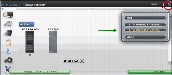
Figure 8-204 Starting TS7700 IBM Knowledge Center
IBM 3592 Tape Drive failure (TS7740 or TS7720T)
When the TS7700 Virtualization Engine determines that one of its tape drives is not operating correctly and requires service (due to read/write errors, fiber interface, or another hardware-related reason), the drive is marked offline and an IBM SSR must be engaged. The following intervention- required message is displayed on the Library Manager Console:
CBR3750I MESSAGE FROM LIBRARY lib: Device xxx made unavailable by a VTS. (VTS z)
Operation of the TS7700 Virtualization Engine continues with a reduced number of drives until the repair action on the drive is complete. To recover, the IBM SSR repairs the failed tape drive and makes it available for the TS7700 Virtualization Engine to use it again.
Power failure
User data is protected in a power failure, because it is stored on the TVC. Any host jobs reading or writing to virtual tapes will fail as they fail with a real IBM 3490E, and they will need to be restarted after the TS7700 Virtualization Engine is available again. When power is restored and stable, the TS7700 Virtualization Engine must be started manually. The TS7700 Virtualization Engine recovers access to the TVC using information available from the TS7700 Virtualization Engine database and logs.
TS7700 Virtualization Engine Tape Volume Cache errors
Eventually, one disk drive module (DDM) or another component might fail in the TS7700 TVC. In this situation, the host is notified by the TS7700, and the operator sees the HYDIN0571E Disk operation in the cache is degraded message. Also, the MI shows the Health Status bar (lower-right corner in Figure 8-204 on page 559) in yellow to warn of a degraded resource in the subsystem. A degraded TVC needs an IBM SSR engagement. The TS7700 Virtualization Engine continues to operate normally during the intervention.
R3.2 has improved the accuracy and comprehensiveness of Health Alert messages and Health Status shown throughout the Management Interface (MI) pages. For instance, new alert messages report that a disk drive module (DDM) has failed in a specific cache drawer, compared to a generic message of degradation in previous levels. Also, MI brings enriched information in graphical format, like in Figure 8-26 on page 320.
Accessor failure and manual mode (TS7740 or TS7720T)
If the TS3500 Tape Library does not have the dual accessors installed, failure of the accessor results in the library being unable to automatically mount physical volumes. If TS3500 Tape Library dual accessors are installed, the second accessor takes over. Then, you can call your IBM SSR to repair the failed accessor.
Gripper failure (TS7740 or TS7720T)
The TS3500 Tape Library has dual grippers. If a gripper fails, library operations continue with the other one. While the gripper is being repaired, the accessor is not available until the repair is complete. If the dual accessors are installed, the second accessor is used until the gripper is repaired. For detailed information about operating the TS3500 Tape Library, see IBM System Storage TS3500 Tape Library with ALMS Operator Guide, GA32-0594.
Out of stacked volumes (TS7740 or TS7720T)
If the tape library runs out of stacked volumes, copying to the 3592 Tape Drives fails, and an intervention-required message is sent to the host and the TS7700 Virtualization Engine MI. All further logical mount requests are delayed by the Library Manager until more stacked volumes are added to the TS3500 Tape Library that is connected to the TS7740 or TS7720T Virtualization Engine. To recover, insert more stacked volumes. Copy processing can
then continue.
then continue.
|
Important: In a TS7720T cluster, only the tape attached partitions are affected.
|
Damaged cartridge pin
The 3592 has a metal pin that is grabbed by the feeding mechanism in the 3592 tape drive to load the tape onto the take-up spool inside the drive. If this pin gets dislodged or damaged, follow the instructions in IBM TotalStorage Enterprise Tape System 3592 Operators Guide, GA32-0465, to correct the problem.
|
Important: Repairing a 3592 tape must be done only for data recovery. After the data is moved to a new volume, replace the repaired cartridge.
|
Broken tape
If a 3592 tape cartridge is physically damaged and unusable (the tape is crushed, or the media is physically broken, for example), the TS7740 or TS7720T Virtualization Engine cannot recover the contents configured as a stand-alone cluster. If this TS7700 cluster is part of a grid, the damaged tape contents (active logical volumes) are retrieved from other clusters, and the TS7700 has those logical volumes brought in automatically (given that those logical volumes had another valid copy within the grid).
Otherwise, this is the same for any tape drive media cartridges. You can make a list of logical volumes that are in that stacked volume, and check with your IBM SSR to learn whether IBM services are available to attempt data recovery from a broken tape.
Logical mount failure
When a mount request is received for a logical volume, the TS7700 Virtualization Engine determines whether the mount request can be satisfied and, if so, tells the host that it will process the request. Unless an error condition is encountered in the attempt to mount the logical volume, the mount operation completes and the host is notified that the mount was successful. With the TS7700 Virtualization Engine, the way that a mount error condition is handled is different than with the prior generations of VTS.
With the prior generation of VTS, the VTS always indicated to the host that the mount completed even if a problem had occurred. When the first I/O command is sent, the VTS fails that I/O because of the error. This results in a failure of the job without the opportunity to try to correct the problem and try the mount again.
With the TS7700 Virtualization Engine subsystem, if an error condition is encountered during the execution of the mount, rather than indicating that the mount was successful, the TS7700 Virtualization Engine returns completion and reason codes to the host indicating that a problem was encountered. With DFSMS, the logical mount failure completion code results in the console messages shown in Example 8-2.
Example 8-2 Unsuccessful mount completion and reason codes
CBR4195I LACS RETRY POSSIBLE FOR JOB job-name
CBR4171I MOUNT FAILED. LVOL=logical-volser, LIB=library-name, PVOL=physical-volser, RSN=reason-code
...
CBR4196D JOB job-name, DRIVE device-number, VOLSER volser, ERROR CODE error-code. REPLY ’R’ TO RETRY OR ’C’ TO CANCEL
Reason codes provide information about the condition that caused the mount to fail:
•For example, look at CBR4171I. Reason codes are documented in the IBM Knowledge Center. As an exercise, assume RSN=32. In the IBM Knowledge Center, you see this reason code:
Reason code x’32’: Local cluster recall failed; the stacked volume is unavailable.
•CBR4196D: Error code shows in the format 14xxIT:
– 14 is the permanent error return code.
– xx is 01 if the function was a mount request or 03 if the function was a wait request.
– IT is the permanent error reason code. The recovery action to be taken for each CODE.
– In this example, it is possible to have a value of 140194 for the error code, which means xx=01: Mount request failed.
•IT=94: Logical volume mount failed. An error was encountered during the execution of the mount request for the logical volume. The reason code that is associated with the failure is documented in CBR4171I. The first book title includes the acronyms for message IDs, but the acronyms are not defined in the book.
For CBR messages, see z/OS MVS System Messages, Vol 4 (CBD-DMO), SA38-0671, for an explanation of the reason code and for specific actions that you might need to take to correct the failure. See z/OS DFSMSdfp Diagnosis, SC23-6863, for OAM return and reason codes. Take the necessary corrective action and reply ‘R’ to try again. Otherwise, reply ‘C’ to cancel.
|
Tip: Always see the appropriate documentation (TS7700 IBM Knowledge Center and MVS System Messages) for the meaning of the messages and the applicable recovery actions.
|
Orphaned logical volume
This situation occurs when the TS7700 Virtualization Engine database has a reference to a logical volume but no reference to its physical location. This can result from hardware or internal processing errors. If you run into an orphaned logical volume message, contact your IBM SSR.
Internal-external label mismatch
If a label mismatch occurs, the stacked volume is ejected to the Convenience Input/Output Station, and the intervention-required condition is posted at the TS7740 or TS7720T Virtualization Engine MI and sent to the host console (Example 8-3).
Example 8-3 Label mismatch
CBR3750I MESSAGE FROM LIBRARY lib: A stacked volume has a label mismatch and has been ejected to the Convenience Input/Output Station.
Internal: xxxxxx, External: yyyyyy
Internal: xxxxxx, External: yyyyyy
The host is notified that intervention-required conditions exist. Investigate the reason for the mismatch. If possible, relabel the volume to use it again.
Failure during reclamation
If there is a failure during the reclamation process, the process is managed by the TS7740 or TS7720T Virtualization Engine microcode. No user action is needed because recovery is managed internally.
Excessive temporary errors on stacked volume
When a stacked volume is determined to have an excessive number of temporary data errors, to reduce the possibility of a permanent data error, the stacked volume is placed in read-only status.
8.6.2 TS7700 Virtualization Engine LIC processing failure
If a problem develops with the TS7700 Virtualization Engine Licensed Internal Code (LIC), the TS7700 Virtualization Engine sends an intervention-required message to the TS7700 Virtualization Engine MI and host console, and attempts to recover. In the worst case, this can involve a restart of the TS7700 Virtualization Engine itself. If the problem persists, you need to contact your IBM SSR. The intervention-required message shown in Example 8-4 is sent to the host console.
Example 8-4 VTS software failure
CBR3750I MESSAGE FROM LIBRARY lib: Virtual Tape System z has a CHECK-1 (xxxx) failure
The TS7700 Virtualization Engine internal recovery procedures handle this situation and restart the TS7700 Virtualization Engine. See Chapter 12, “Disaster Recovery” on page 725 for more details.
8.7 TS7700 Management Interface considerations
In the TS7700 Management Interface, some operations or functions might be unavailable or disabled, depending on the cluster configuration (TS7740, or TS7720 or TS7720T). Functions or operations that only apply to a disk-only configuration (TS7720 or resident partition in TS7720T configuration) might be unavailable or disabled on a tape attached configuration (TS7740 or a tape partition in a TS7720T) and vice-versa. Also, some operations or functions might be available or disabled depending on whether the cluster is part of a grid configuration or not.
The following figures show the Cluster Summary page for disk-only and tape-attached configurations, highlighting some particularities.
Monitoring the health with TS7720
Figure 8-205 shows you where the Health Status bar is displayed in a TS7720 Virtualization Engine configuration. The TS7720 Virtualization Engine on the left is configured with an expansion frame. Compare that with the illustration of a TS7720 Virtualization Engine with only the base frame on the right.

Figure 8-205 TS7720 Virtualization Engine MI health and monitoring options
You can get details about the health state of each component of the TS7700 by hovering the mouse over the picture that represents your cluster. Also, you can look at the components in the back of the frame by clicking the blue circular arrow near the lower-right corner of the frame. This arrow flips the picture, showing the back side. Again, hover the mouse over the components for the health details of those components.
Compare Figure 8-205 on page 564 with Figure 8-206, which shows a TS7740 or TS7720T Virtualization Engine. Figure 8-206 shows the TS7720T MI. A TS3500 Tape Library icon is displayed for the TS7740 or the TS7720T Virtualization Engine. Compare it with Figure 8-205 on page 564 (TS7720 clusters, disk-only). By hovering the mouse over the TS3500 icon, you can see the tape library and tape drive health information.

Figure 8-206 Tape Attached Virtualization Engine MI
For the remaining possible options, see 8.2, “TS7700 Virtualization Engine Management Interface” on page 295.
1 The server address value in the Primary or alternative Server URL can be an IP address or DNS address. Valid IP formats include the following formats:
- IPv4: 32 bits. Four decimal numbers, 0 - 255, separated by periods, for example, 12.345.678.
- IPv6: 128-bit hexadecimal value enclosed by brackets, separated into 16-bit field by colons, for example, [1234:9abc:0::1:cdef:8]. Note that leading zeros (0) can be omitted. A double colon (::) means a field of 0s (:0000:).
..................Content has been hidden....................
You can't read the all page of ebook, please click here login for view all page.