


Fibre Connection Express
This chapter describes the Fibre Connection (FICON) Express features and the protocols that they support on IBM Z platforms.
This chapter includes the following sections:
4.1 FICON Express description
FICON provides the non-drop distance 9 - 100 km. FICON also increases the link data rate to 1, 2, 4, 8, or 16 Gbps depends on the FICON features:
•FICON Express16S+ and FICON Express16S features automatically negotiate to 4, 8, or 16 Gbps.
•FICON Express8S and FICON Express8 features automatically negotiate to 2, 4, or 8 Gbps.
•FICON Express4 features auto-negotiate to 1, 2, or 4 Gbps.
The FICON implementation enables full-duplex data transfer, so data travels in both directions simultaneously. FICON also enables multiple concurrent I/O operations.
|
Terminology: Throughout this chapter, FICON refers to the FICON Express4, FICON Express8, FICON Express8S, FICON Express16S, and FICON Express16S+ features, except when the function being described is applicable to a specific FICON feature type.
|
The FICON channel matches data storage and access requirements with the latest technology in servers, control units, and storage devices. FICON channels allow faster and more efficient data transfer while allowing you to use their currently installed single mode and multimode fiber optic cabling plant.
FICON uses long wavelength (LX) and short wavelength (SX) transceivers with multimode and single mode fiber optic media for data transmission.
4.1.1 FICON modes and topologies
IBM Z supports the FICON channel to operate in one of two modes:
•FICON native mode (FC)
•Fibre Channel Protocol (FCP)
|
Note: The z14 supports the FICON Express8S only when carried forward on an upgrade.
The IBM z13 and IBM z13s are the last systems to support FICON Express8 features. The z13 and z13s support the FICON Express8 features only when carried forward on an upgrade. The features cannot be ordered for new builds of z14, z13, and z13s platforms. Review the use of your installed FICON Express8 channels and, where possible, upgrade to FICON Express16S+ or FICON Express 16S features.
The IBM zEnterprise EC12 (zEC12) and IBM zEnterprise BC12 (zBC12) are the last platforms to support FICON Express4 features. zEC12 and zBC12 support the FICON Express4 feature only when carried forward on an upgrade. The feature cannot be ordered for new builds of z13, z13s, zEC12, or zBC12 systems. Review the use of your installed FICON Express4 channels and, where possible, upgrade to FICON Express16S or FICON Express8S features.
|
FICON native mode (FC)
As shown in Figure 4-1, a FICON channel in FICON native mode (CHPID type FC) can access FICON native interface control units by using the following topologies:
•Point-to-point (direct connection)
•Switched point-to-point (through a Fibre Channel switch)
•Cascaded FICON Directors (through two Fibre Channel switches)
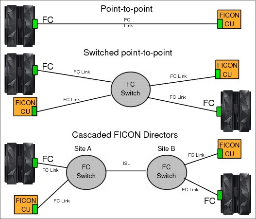
Figure 4-1 Z supported FICON native topologies
A FICON native channel also supports channel-to-channel communications. The FICON channel at each end of the FICON CTC connection, which supports the FCTC control units, can also communicate with other FICON native control units, such as disk storage devices and tape. At least one end of the FICON CTC connection must be an IBM Z installation.
Fibre Channel Protocol (FCP) mode
A FICON channel in Fibre Channel Protocol mode (CHPID type FCP) can access FCP devices in either of the following ways:
•A FICON channel in FCP mode through a single Fibre Channel switch or multiple switches to a Small Computer System Interface (SCSI) device
•A FICON channel in FCP mode through a single Fibre Channel switch or multiple switches to a Fibre Channel-to-SCSI bridge
The FICON features support Fibre Channel and SCSI devices in IBM z/VM,
IBM z/VSE, and Linux on z Systems operating systems, as shown in Figure 4-2.
IBM z/VSE, and Linux on z Systems operating systems, as shown in Figure 4-2.

Figure 4-2 IBM Z FCP topologies
On IBM Z, point-to-point connections can be used to access data that is stored on devices without the use of a Fibre Channel switch. In addition, an operating system or other stand-alone program can be IPLed through a point-to-point connection by using the SCSI IPL feature. N_Port ID Virtualization is not supported by FCP point-to-point. For more information, see “Worldwide port name tool” on page 43.
The FCP support allows z/VM, z/VSE, and Linux on z Systems operating systems to access industry-standard SCSI devices. For disk applications, these FCP storage devices use fixed block (512-byte) sectors rather than the extended count key data (IBM ECKD) format.
4.1.2 FCP Channel
The FC-FCP standard was developed by the International Committee of Information Technology Standards (INCITS) and published as an ANSI standard. The IBM Z FCP I/O architecture conforms to the FC standards specified by the INCITS. For more information about the FC standards, see the INCITS Technical Committee T11 website and their page for SCSI Storage Interfaces (this is the committee within INCITS that is responsible for the Fibre Channel Interface).
FICON channels in FCP mode provide full fabric attachment of SCSI devices to the operating system images by using the Fibre Channel Protocol and provide point-to-point attachment of SCSI devices. This technique allows z/VM, z/VSE, and Linux on z Systems to access industry-standard SCSI storage controllers and devices.
The FCP channel full fabric support means that multiple numbers of directors or switches can be placed between the Z platform and the SCSI device. This technique allows many hops through a storage area network (SAN) and provides improved use of intersite connected resources and infrastructure. This expanded ability to attach storage devices provides more choices for storage solutions and the ability to use existing storage devices. This configuration can facilitate the consolidation of UNIX server farms onto Z platforms, protecting investments in SCSI-based storage.
For a list of switches, storage controllers, and devices that are verified to work in a Fibre Channel network that is attached to FCP channel, and for software requirements to support FCP and SCSI controllers or devices, see the I/O Connectivity website.
FICON channels in FCP mode are based on the Fibre Channel standards that are defined by INCITS and published as ANSI standards. FCP is an upper-layer Fibre Channel mapping of SCSI on a common stack of Fibre Channel physical and logical communication layers.
SCSI is supported by a wide range of controllers and devices, complementing the classical storage attachment capability through FICON channels. FCP is the base for industry-standard Fibre Channel networks or SANs.
Fibre Channel networks consist of servers, storage controllers, and devices as end nodes, which are interconnected by Fibre Channel switches, directors, and hubs. Switches and directors are used to build Fibre Channel networks or fabrics. Fibre Channel Arbitrated Loops (FC-ALs) can be constructed by using Fibre Channel hubs. In addition, different types of bridges and routers can be used to connect devices with different interfaces, such as parallel SCSI. All of these interconnections can be combined in the same network.
SCSI is implemented by many vendors in many different types of storage controllers and devices. These controllers and devices are widely accepted in the marketplace and have proven to be able to meet the reliability, availability, and serviceability (RAS) requirements of many environments.
FICON channels in FCP mode use the queued direct input/output (QDIO) architecture for communication with the operating system. The QDIO architecture for FCP channels derives from the QDIO architecture, which was defined initially for the OSA-Express features and for HiperSockets communications.
FCP channels do not use control devices. Instead, data devices that represent QDIO queue pairs are defined, consisting of a request queue and a response queue. Each queue pair represents a communication path between an operating system and the FCP channel. It allows an operating system to send FCP requests to the FCP channel through the request queue. The FCP channel uses the response queue to pass completion indications and unsolicited status indications to the operating system. Figure 4-3 on page 42 illustrates this process.
HCD/IOCP is used to define the FCP channel type and QDIO data devices. However, there is no definition requirement for the Fibre Channel storage controllers and devices, or for the Fibre Channel interconnect units, such as switches, directors, and bridges. The FCP industry standard architecture requires that the Fibre Channel devices (end nodes) in a Fibre Channel network are addressed by using worldwide names (WWNs), Fibre Channel Identifiers (IDs), and logical unit numbers (LUNs).
These addresses are configured on an operating system level and passed to the FCP channel together with the corresponding Fibre Channel I/O or service request through a logical QDIO device (queue).
Figure 4-3 summarizes the necessary FCP I/O definitions and compares them to FICON I/O definitions.

Figure 4-3 I/O definition comparison (FCP to FICON)
Channel and device sharing
An FCP channel can be shared among multiple Linux operating systems, each running in a logical partition or as a guest operating system under z/VM. To access the FCP channel, each operating system needs its own QDIO queue pair, which is defined as a data device on an FCP channel in the HCD/IOCP.
Each FCP channel can support up to 480 QDIO queue pairs with the z14, z13, z13s, zEC12, and zBC12. This support allows each FCP channel to be shared among 480 operating system instances (with a maximum of 252 guests per logical partition).
Host operating systems that share access to an FCP channel can establish up to 2048 concurrent connections to up to 512 different remote Fibre Channel ports that are associated with Fibre Channel controllers. The total number of concurrent connections to end devices, identified by LUNs, must not exceed 4096.
Although multiple operating systems can concurrently access the same remote Fibre Channel port through a single FCP channel, Fibre Channel devices, identified by their LUNs, can be reused only serially. For two or more unique operating system instances to share concurrent access to a single Fibre Channel or SCSI device (LUN), each of these operating systems must access this device through a different FCP channel.
If two or more unique operating system instances attempt to share concurrent access to a single Fibre Channel or SCSI device (LUN) over the same FCP channel, a LUN sharing conflict occurs and errors result. A way to alleviate this sharing conflict on Z platforms is to use N_Port ID Virtualization.
Worldwide port name tool
The worldwide port name tool assigns WWPNs to each FCP channel or port by using the same WWPN assignment algorithms that a system uses when you are assigning WWPNs for channels that use NPIV. Therefore, the SAN can be set up in advance, allowing operations to proceed much faster after the system is installed.
The WWPN tool can calculate and show WWPNs for both virtual and physical ports ahead of system installation. This feature means that the SAN configuration can be retained rather than altered by assigning a WWPN to physical FCP ports when a FICON feature is replaced.
The WWPN tool takes an adhesive file that contains the FCP-specific I/O device definitions and creates the WWPN assignments that are required to set up the SAN. A binary configuration file that can be imported later by the system is also created. The CSV (.csv) file can either be created manually or exported from the hardware configuration definition/hardware configuration manager (HCD/HCM).
The WWPN tool can be downloaded from the Tools section of IBM Resource Link (requires registration).
FCP SCSI IPL feature enabler
This function allows IPLing an operating system from an FCP channel-attached disk to run either in a logical partition or as a guest operating system under z/VM. In particular, SCSI IPL can directly IPL a Linux operating system that was installed previously on a SCSI disk. Therefore, there is no need for a classical channel-attached device (FICON), such as an ECKD disk control unit, to install and IPL a Linux operating system.
The IPL device is identified by its SAN address, consisting of the WWPN of the disk controller and the LUN of the IPL device. SCSI IPL is supported in the following conditions:
•FCP access control
•Point-to-point connections
•N-Port ID Virtualization (NPIV)
A stand-alone-dump program can also be IPLed from an FCP channel that is attached to a SCSI disk. The stand-alone-dump program can also store the generated dumped data on a SCSI disk. z/VM support of SCSI IPL allows Linux and other guest operating systems that support this feature to be IPLed from an FCP-attached SCSI disk when z/VM is running on an IBM Z platform. Therefore, Linux guests can be started and run completely from an FCP channel-attached disk.
For more information about FCP SCSI IPL, see Linux on zSeries: Fibre Channel Protocol Implementation Guide, SG24-6344.
FCP multipathing concept
Multipath access to disk subsystems is a basic feature with the channel subsystem on
IBM Z platforms. FICON connections support multiple hardware paths to any physical disk device. The z14, z13, z13s, zEC12, and zBC12 handle multipathing invisibly by the operating system. With FICON channels, the operating system is presented a single device for I/O operations, and multipathing happens under channel subsystem control.
IBM Z platforms. FICON connections support multiple hardware paths to any physical disk device. The z14, z13, z13s, zEC12, and zBC12 handle multipathing invisibly by the operating system. With FICON channels, the operating system is presented a single device for I/O operations, and multipathing happens under channel subsystem control.
Multipathing over FCP is different. With FCP multipathing on Linux on z Systems, each path to each LUN appears to the operating system as a separate device. For example, if there are four paths to five LUNs, the Linux system sees 20 SCSI devices. This configuration means that there must be another layer of code between the Linux file system layer and the SCSI subsystem. This extra layer handles all of the coordination between the raw paths and the higher-level file subsystem. Currently, supported distributions use Multiple Device Administration (mdadm) tools. For more information, see the RAID setup website.
FCP access control
The ability to control access to nodes and devices is provided as a function in switches and controllers, and is called LUN masking and zoning. LUN masking and zoning can be used to prevent systems from accessing storage that they are not permitted to access:
LUN masking A LUN represents a portion of a controller, such as a disk device. With the use of LUNs, a controller can be logically divided into independent elements or groups of elements. Access to these LUNs can be restricted to distinctive WWPNs as part of the controller configuration. This method is known as LUN masking.
Zoning Segmentation of a switched fabric is achieved through zoning. It can be used to fence off certain portions of the switched fabric, allowing only the members of a zone to communicate within that zone. All others that attempt to access from outside of that zone are rejected.
I/O devices
The IBM Z FCP channel implements the FCP standard as defined by the INCITS Fibre Channel Protocol for SCSI (FC-FCP) and Fibre Channel Protocol for SCSI Second Version (FCP-2), and the relevant protocols for the SCSI-2 and SCSI-3 protocol suites. Theoretically, each device that conforms to these protocols works when attached to an IBM Z FCP channel. However, experience shows that there are small deviations in the implementations of these protocols.
Also, for certain types of FCP and SCSI controllers and devices, specific drivers in the operating system might be required to use all of the capabilities of the controller or device. The drivers might also be required to cope with unique characteristics or deficiencies of the device.
|
Note: Do appropriate conformance and interoperability testing to verify that a particular storage controller or device can be attached to an IBM Z FCP channel in a particular configuration. For example, test that it can be attached through a particular type of Fibre Channel switch, director, or point-to-point connection.
|
Hardware assists
A complementary virtualization technology is available for z14, z13, z13s, zEC12, and zBC12 systems. The technology includes these capabilities:
•QDIO Enhanced Buffer-State Management (QEBSM), with two hardware instructions that are designed to eliminate the overhead of hypervisor interception
•Host Page-Management Assist (HPMA), which is an interface to the z/VM main storage management function that allows the hardware to assign, lock, and unlock page frames without z/VM hypervisor assistance
These hardware assists allow a cooperating guest operating system to start QDIO operations directly to the applicable channel, without interception by z/VM, providing additional performance improvements. This support is integrated in the z14, z13, z13s, zEC12, and zBC12. Consult the appropriate Preventive Service Planning (PSP) buckets (3906DEVICE, 2964DEVICE, 2965DEVICE, 2828DEVICE, and 2827DEVICE) before implementation.
Support of T10-DIF for enhanced reliability
Because high reliability is important for maintaining the availability of business-critical applications, the IBM Z FCP implements support of the ANSI T10 Data Integrity Field (DIF) standard. Data integrity protection fields are generated by the operating system and propagated through the SAN. IBM Z helps to provide added end-to-end data protection between the operating system and the storage device.
An extension to the standard, Data Integrity Extensions (DIX), provides checksum protection from the application layer through the host bus adapter (HBA), where cyclical redundancy check (CRC) protection is implemented.
T10-DIF support by the FICON Express16s+, FICON Express16s, FICON Express8S, and FICON Express8 features, when defined as CHPID type FCP, is exclusive to z14, z13, z13s, zEC12, and zBC12. Use of the T10-DIF standard requires support by the operating system and the storage device.
4.1.3 FCP and FICON mode characteristics
The single largest difference between the FICON channel (FC) and FCP channel mode types is the treatment of data access control and security. FICON channels rely on multiple image facility (MIF) to address concerns about shared channels and devices. MIF provides ultra-high access control and security of data so that one operating system image and its data requests cannot interfere with another operating system’s data requests. With the introduction of IBM Z, MIF continues this ultra-high level of access control and security across channel subsystems (CSSes).
FCP and MIF
Linux guest operating systems under z/VM can have access to an FCP channel defined to the z/VM operating system. Using MIF, an FCP channel can also be shared between Linux Logical Partitions and z/VM Logical Partitions with Linux guests.
The FCP industry-standard architecture does not use the data access control and security functions of MIF. As a result, FCP has the following limitations:
•Channel sharing
When NPIV is not implemented, and if multiple Linux images share an FCP channel and all of the Linux images have connectivity to all of the devices that are connected to the FCP fabric, all of the Linux images use the same worldwide port name (WWPN). They use this name to enter the fabric and are indistinguishable from each other within the fabric. Therefore, the use of zoning in switches and LUN masking in controllers is not effective in creating appropriate access controls among the Linux images.
By using NPIV, each operating system that shares an FCP channel is assigned a unique WWPN. The WWPN can be used for device-level access control in storage controllers (LUN masking) and in switch-level access control (zoning).
•Device sharing
Without using NPIV, an FCP channel prevents logical units from being opened by more than one Linux image at a time. Access is on a first-come, first-served basis. This system prevents problems with concurrent access from Linux images that are share a FCP channel and, therefore, the same WWPN. This serialization means that one Linux image can block other Linux images from accessing the data on one or more logical units unless the sharing images (z/VM guests) are not in contention.
FICON versus FCP
FICON and FCP have other significant differences. Certain differences are fundamental to the IBM Z family, whereas others are fundamental to the two channel architectures. Still others depend on the operating system and the device being attached. Without taking the operating system and the storage device into consideration, I/O connectivity through IBM Z FCP and FICON channels has the following differences:
•Direct connection
With all FICON features on z14, z13, z13s, zEC12, and zBC12, storage controllers can be directly connected to the channel by using point-to-point attachment when in FCP mode. There is no need for a director or switch between the FCP channel and storage controllers. Although N_Port ID Virtualization is supported in switch topology, it is not supported in a point-to-point topology.
•Switch topology
FCP channels support full fabric connectivity, meaning that several directors or switches can be used between a Z platform and the device. With the FICON cascaded director support, the FICON storage network topology is limited to a two-director, single-hop configuration.
•Enterprise fabric
The use of cascaded FICON Directors ensures the implementation of a high-integrity fabric. For FCP, a high-integrity fabric solution is not mandatory, although it must be considered. For example, if an FCP inter-switch link (ISL) must be moved, data potentially might be sent to the wrong path without notification. This type of error does not happen on an enterprise fabric with FICON.
•Transmission data checking
When a transmission is sent through an FCP channel, because of its full fabric capability, FCP checks data for each leg of that transmission. FICON also checks intermediate data.
•Serviceability
– Licensed Internal Code (LIC) updates and z14, z13, zEC12, and zBC12 allow FCP concurrent patches. FICON channels, when configured as CHPID type FCP, support concurrent patches, allowing the application of a LIC without requiring a configuration of off/on. This is an exclusive FCP availability feature that is available with all FICON features.
– The FICON Express16s+, FICON Express16s, FICON Express8S, FICON Express8, and FICON Express4 features have Small Form-factor Pluggable (SFP) optics to permit each channel to be individually serviced during a fiber optic module failure. The traffic on the other channels on the same feature can continue to flow if a channel requires servicing.
•Problem determination
– Request Node Identification (RNID)
RNID assists with the isolation of FICON cabling detected errors. Resolving fiber optic cabling problems can be a challenge in a fiber optic environment with extended distances. To facilitate resolution, the operating system can request the RNID data for each device or control unit that is attached to native FICON channels. You can then display the RNID data by using an operator command. RNID is exclusive to the z14, z13, zEC12, and zBC12, and is supported by all FICON features (CHPID type FC) and by z/OS.
– Link incident reporting
Link incident reporting is integral to the FICON architecture. When a problem on a link occurs, this mechanism identifies the two connected nodes between which the problem occurred, leading to faster problem determination and service. For FCP, link incident reporting is not a requirement for the architecture, although it might be offered as an optional switch function. Therefore, important problem determination information might not be available if a problem occurs on an FCP link.
IBM Z allows z/OS to register for all FICON link incident records. This feature improves your ability to capture data for link incident analysis across multiple systems. This function is supported by z/OS version 1.8 or later.
– Simplified problem determination
To more quickly detect fiber optic cabling problems in a storage area network, all FICON channel error information is forwarded to the HMC. This function facilitates detection and reporting trends and thresholds for the channels with aggregate views, including data from multiple systems.
Problem determination can be simplified by using the HMC to pinpoint fiber optic cabling issues in your SAN fabric without involving IBM service personnel.
All FICON channel error information is forwarded to the HMC. In the HMC, it is analyzed to detect and report the trends and thresholds for all FICON channels on z14, z13, zEC12, and zBC12. The Fibre Channel Analyzer task on the HMC can be used to display analyzed information about errors on FICON channels (CHPID type FC) of attached Support Elements. Data includes information about the PCHID, CHPID, channel type, source link address, and destination link address where the error occurred. This report shows an aggregate view of the data and can span multiple systems.
With z13, similar FICON problem determination tools have been implemented for FCP channels. These channel problem determination tools for FCP channels include analyze functions such as analyze channel information, subchannel data, device status, serial link status, and link error statistic block. In addition to the analyze functions, fabric status login and SAN explorer functions are also available. These FCP problem determination tools are accessed from the HMC in the same way as for the FICON channels.
– FICON purge path extended
The purge path extended function enhances FICON problem determination. FICON purge path error recovery function is extended so that it transfers error-related data and statistics between the channel and entry switch and the control unit and its entry switch to the host operating system. FICON purge path extended use requires a switch or device that supports this function. The purge path extended function for FCP channels is available on z14 and z13.
•FICON error recovery
Z platforms, z/OS, and I/O recovery processing are designed to allow the system to detect switch/director fabric problems that might cause FICON links to fail and recover multiple times in a short time.
This feature allows the system to detect these conditions and keep an affected path offline until an operator action is taken. This process is expected to limit the performance impacts of switch/director fabric problems. The FICON error recovery function is available in z/OS.
Forward Error Correction
Forward Error Correction (FEC) is a technique that is used for controlling errors in data transmission over unreliable or noisy communication channels. By adding redundancy and error-correcting code (ECC) to the transmitted information, the receiver detects and corrects a limited number of errors in the information instead of requesting a retransmission. This process improves the reliability and bandwidth utilization of a connection by saving retransmissions due to bit errors. This advantage is true especially for connections across long distances, such as an ISL in an IBM Geographically Dispersed Parallel Sysplex™ (IBM GDPS®) MetroMirror environment.
FICON Express16S+ and FICON Express16s support FEC coding on top of their 64 b/66 b data encoding for 16 Gbps connections. Their FEC design can correct up to 11 bit errors per 2112 bits transmitted. Thus, when connected to devices that support FEC at 16 Gbps connections, the FEC design allows FICON Express16S+ or FICON Express16S channels to operate at higher speeds over longer distances and with reduced power and higher throughput. At the same time, the FIC design maintains the same reliability and robustness that FICON channels are known for.
With the IBM DS8870 or later, z14, z13, and z13s can extend the use of FEC to the fabric N_Ports for a completed end-to-end coverage of 16 Gbps FC links. For more information, see the IBM DS8880 and IBM z Systems Synergy, REDP-5186.
FICON dynamic routing
With the IBM z14, z13 and z13s, FICON channels are no longer restricted to the use of static SAN routing policies for ISLs for cascaded FICON directors. IBM Z now supports dynamic routing in the SAN with the FICON Dynamic Routing (FIDR) feature. It supports the dynamic routing policies provided by the FICON director manufacturers, such as Brocade’s Exchange Based Routing 7 (EBR 7) and Cisco's Open Exchange ID Routing (OxID).
With FIDR, z14, z13, and z13s has advantages for performance and management in configurations with ISL and cascaded FICON directors:
•Support sharing of ISLs between FICON and FCP (PPRC or distributed)
•Better balanced I/O traffic between all available ISLs
•Improved utilization of the FICON director and ISL
•Easier management with a predicable and repeatable I/O performance
FICON dynamic routing can be enabled by defining dynamic routing capable switches and control units in HCD. Also, z/OS has implemented a health check function for FICON dynamic routing.
FICON performance
See the latest FICON and FCP performance information at the IBM I/O Connectivity web page.
4.2 FICON elements
FICON enables multiple concurrent I/O operations to occur simultaneously to multiple control units. FICON channels also permit intermixing of large and small I/O operations on the same link. The data center I/O configuration now has increased flexibility for connectivity because of the increased I/O rate, increased bandwidth, and multiplexing of mixed workloads.
4.2.1 FICON channel
FICON channel architecture is compatible with the following protocols:
•Fibre Channel Physical and Signaling standard (FC-FS)
•Fibre Channel Switch Fabric and Switch Control Requirements (FC-SW)
•Fibre Channel Single-Byte-3 (FC-SB-3) and Fibre Channel Single-Byte-4 (FC-SB-4) standards
Cabling specifications are defined by the Fibre Channel - Physical Interface - 4 (FC-PI-4) standard and used by IBM Z FICON features. Table 4-1 identifies cabling types and link data rates that are supported in the FICON environment, including their allowable maximum distances and link loss budget. The link loss budget is derived from the channel insertion loss budget that is defined by the FC-PI-4 standard (Revision 8.00).
Table 4-1 Fiber optic cabling for FICON: Maximum distances and link loss budget
|
FC-PI-4
Fiber core (light source)
|
Cable Type
Category
|
2 Gbps
|
4 Gbps
|
8 Gbps
|
16 Gbps
|
10 Gbps ISL1
|
|||||
|
Distance in meters
|
Link- loss budget in dB
|
Distance in meters
|
Link- loss budget in dB
|
Distance in meters
|
Link- loss budget in dB
|
Distance in meters
|
Link- loss budget in dB
|
Distance in meters
|
Link- loss budget in dB
|
||
|
9 µm SM (10 km LX)
|
OS1/OS2
|
10000
|
7.8
|
10000
|
7.8
|
10000
|
6.4
|
10000
|
6.4
|
10000
|
6.4
|
|
9 µm SM (4 km LX)
|
OS1/OS2
|
4000
|
4.8
|
4000
|
4.8
|
N/A
|
N/A
|
N/A
|
N/A
|
N/A
|
N/A
|
|
50 µm MM
4700 MHz km
(SX laser)
|
OM4
|
500
|
3.31
|
400
|
2.95
|
190
|
2.19
|
125
|
1.95
|
N/A
|
N/A
|
|
50 µm MM
2000 MHz·km
(SX laser)
|
OM3
|
500
|
3.31
|
380
|
2.88
|
150
|
2.04
|
100
|
1.86
|
300
|
2.6
|
|
50 µm MM
500 MHz·km
(SX laser)
|
OM2
|
300
|
2.62
|
150
|
2.06
|
50
|
1.68
|
35
|
1.63
|
82
|
2.3
|
|
62.5 µm MM
200 MHz·km
(SX laser)
|
OM1
|
150
|
2.1
|
70
|
1.78
|
21
|
1.58
|
N/A
|
N/A
|
N/A
|
N/A
|
1 ISL between two FICON Directors.
|
Note: IBM does not support a mix of 50 µm and 62.5 µm fiber optic cabling in the same physical link.
|
When an application performs an I/O operation to a device represented by a unit control block (UCB), it initiates an I/O request by using macros or Supervisor Call to the input/output supervisor (IOS). The application or access method also provides the channel program (channel command words (CCWs)) and additional parameters in the operation request block (ORB). This request is queued on the UCB. The IOS services the request from the UCB on a priority basis.
The IOS then issues a start subchannel (SSCH) instruction, with the subsystem identifier (SSID) that represents the device and the ORB as operands. The CSS is signaled to perform the operation. This flow is shown in Figure 4-4.
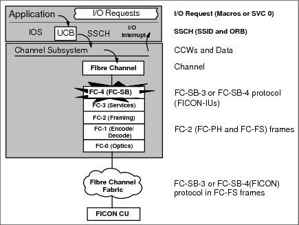
Figure 4-4 FICON channel operation flow
The most appropriate FICON channel is selected by the CSS. The FICON channel fetches channel programs (CCWs) prepared by the application, fetches data from memory (write) or stores data into memory (read), and presents the status of the operation to the application (I/O interrupt).
The z/Architecture channel commands, data, and status are packaged by the FICON channel into FC-SB-3 or FC-SB-4 (FC-4 layer) Information Units (IUs). IUs from several different I/O operations to the same or different control units and devices are multiplexed or demultiplexed by the FC-2 layer (framing). These FC-2 frames, with encapsulated FC-SB-3 or FC-SB-4 IUs, are encoded or decoded by the FC-1 layer (encode or decode) and sent to or received from the FC-0 fiber optic medium (optics).
On a FICON channel, CCWs are transferred to the control unit without waiting for the first command response from the control unit or for a CE/DE after each CCW execution. The device presents a logical end to the control unit after each CCW execution. If the last CCW of the CCW chain has been run by the device, the control unit presents CE/DE to the channel. Figure 4-5 shows a CCW operation on a FICON channel that uses CCW chaining.

Figure 4-5 CCW chaining
4.2.2 High Performance FICON for IBM z Systems
High Performance FICON for IBM z Systems (zHPF) is an enhancement of the FICON channel architecture that is compatible with these protocols:
•Fibre Channel Physical and Signaling standard (FC-FS)
•Fibre Channel Switch Fabric and Switch Control Requirements (FC-SW)
•Fibre Channel Single-Byte-4 (FC-SB-4) standards
Using zHPF with the FICON channel, the z/OS operating system, and the control unit reduces the FICON channel overhead. This goal is achieved by protocol optimization and reducing the number of IUs processed, resulting in more efficient use of the fiber link.
The FICON Express16S+, FICON Express16S, FICON Express8S, FICON Express8, and FICON Express4 features support both the existing FICON architecture and the zHPF architecture. From the z/OS point of view, the existing FICON architecture is called command mode, and the zHPF architecture is called transport mode. A parameter in the ORB is used to determine whether the FICON channel is running in command or transport mode.
The mode that is used for an I/O operation depends on the control unit that is supporting zHPF and the settings in the z/OS operating system. An IECIOSxx parameter and SETIOS commands in z/OS can enable or disable zHPF. Support is also added for the D IOS, ZHPF system command to indicate whether zHPF is enabled, disabled, or not supported on the system.
During link initialization, both the channel and the control unit indicate whether they support zHPF. The Process Login (PRLI) support indicator is presented in response to the RNID Extended Link Services (ELS). If PRLI is supported, the channel sends a PRLI ELS. The PRLI response then indicates that zHPF is supported by the CU.
Similar to the existing FICON channel architecture described previously, the application or access method provides the channel program (CCWs) and parameters in the ORB. Bit 13 in word 1 of the ORB specifies how to handle the channel program in either command mode or transport mode.
The way that zHPF transport mode manages CCW operation is significantly different from the CCW operation for the existing FICON architecture command mode, as shown in Figure 4-6. In command mode, each single CCW is sent to the control unit for execution. In transport mode, all CCWs are sent over the link in one single frame to the control unit. Certain complex CCW chains are not supported by zHPF. Figure 4-6 shows an example of the optimization by a zHPF transport mode read operation.

Figure 4-6 High-performance FICON read operation
The channel sends all the required CCWs and read operations of 4 KB of data in one single frame to the control unit. The control unit transfers the requested data over the link to the channel, followed by a CE/DE if the operation was successful. Less overhead is generated compared with the existing FICON architecture.
Figure 4-7 shows the same reduction of frames and open exchanges for a zHPF transport mode write operation.

Figure 4-7 High-performance FICON write operation
The channel sends all the required CCWs and write operations of 4 KB of data in one frame to the control unit. The control unit responds with XFER when it is ready to receive the data. The channel then sends the 16 KB of data to the control unit. If the control unit successfully receives the data and finishes the write operation, the CE/DE status is sent by the control unit to indicate the completion of the write operation.
zHPF supports multitrack operations. It allows the channel to operate at rates that fully use the bandwidth of a FICON Express channel. The zHPF fully supports multiple tracks of data that can be transferred in a single operation.
For more information about the FICON channel protocol and zHPF, see FICON Planning and Implementation Guide, SG24-6497.
4.2.3 Platform and name server registration in FICON channel
All FICON features on the z14, z13, z13s, zEnterprise EC12 (zEC12), and zEnterprise BC12 (zBC12) support platform and name server registration to the fabric. That support exists only if the FICON feature is defined as channel-path identifier (CHPID) type FC.
Information about the channels that are connected to a fabric, if registered, allow other nodes or SAN managers to query the name server to determine what is connected to the fabric. The following attributes are registered for the z14, z13, z13s, zEC12, and zBC12 systems:
•Platform information:
– Worldwide node name (WWNN). This is the node name of the platform and is the same for all channels that belong to the platform.
– Platform type.
– Host computer type.
– Platform name. The platform name includes vendor ID, product ID, and vendor-specific data from the node descriptor.
•Channel information.
•Worldwide port name (WWPN).
•Port type (N_Port_ID).
•FC-4 types supported.
•Classes of service that are supported by the channel.
The platform and name server registration service are defined in the Fibre Channel - Generic Services 4 (FC-GS-4) standard.
4.2.4 Open exchanges
An open exchange, part of FICON and FC terminology, represents an I/O operation in progress over the channel. Many I/O operations can be in progress over FICON channels at any one time. For example, a disk I/O operation might temporarily disconnect from the channel when performing a seek operation or while waiting for a disk rotation. During this disconnect time, other I/O operations can be managed as follows:
•Command mode open exchanges
In command mode, the number of open exchanges is limited by the FICON Express feature. FICON Express16S+, FICON Express16S, FICON Express8S, FICON Express8, and FICON Express4 allow up to 64 open exchanges. One open exchange (an exchange pair, actually) in command mode is the same as one I/O operation in progress.
•Transport mode open exchanges
In transport mode, one exchange is sent from the channel to the control unit. Then, the same exchange ID is sent back from the control unit to the channel to complete the I/O operation. The maximum number of simultaneous exchanges that the channel can have open with the CU is 750 exchanges. The CU sets the maximum number of exchanges in the status area of the transport mode response IU. The default number is 64, which can be increased or decreased.
In addition, FICON channels can multiplex data transfer for several devices at the same time. This feature also allows workloads with low to moderate control unit cache hit ratios to achieve higher levels of activity rates per channel.
If the open exchange limit is reached, additional I/O operations are refused by the channel, which can result in queues and retries by the operating system.
Extended distances
Degradation of performance at extended distances can be avoided by implementing an enhancement to the industry standard FICON architecture (FC-SB-3). This enhancement is a protocol for persistent IU pacing. Control units that use the architecture can increase the pace count, meaning the number of information units that are allowed to be underway between the channel and the control unit. Extended distance FICON channels remember the last pacing information and use this information for subsequent operations. This feature avoids performance degradation at the start of a new operation.
Information unit pacing helps to optimize the link use and simplifies the requirements for channel extension equipment because more commands can be in flight. Extended distance FICON is apparent to the operating systems and is applicable to all FICON features defined with CHPID type FC.
Modified Indirect Data Address Word
On IBM Z, the Modified Indirect Data Address Word (MIDAW) provides alternatives to using CCW data chaining in channel programs. The MIDAW facility has been added to z/Architecture and can coexist with the current CCW IDAW facility.
MIDAW decreases channel, fabric, and control unit overhead by reducing the number of CCWs and frames that are processed and allows scattering of data in memory for noncontiguous real pages. Although the CCW IDAW function requires all but the first and last IDAW in a list to deal with complete 2 thousand or 4 thousand units of data, the MIDAW facility allows page boundary crossing on either 2 thousand or 4 thousand boundaries. This feature allows access to data buffers anywhere in a 64-bit buffer space.
Figure 4-8 shows an example of MIDAW use.

Figure 4-8 IDAW and MIDAW use
The use of MIDAWs is indicated by the MIDAW bit (flag bit 7) in the CCW. The last MIDAW in the list has a last flag set, indicated by L in Figure 4-8. MIDAW provides significant performance benefits, especially when processing extended format data sets with FICON channels.
FICON link
The transmission medium for the FICON interface is a fiber optic cable. Physically, it is a pair of optical fibers that provide two dedicated, unidirectional, serial-bit transmission lines. Information in a single optical fiber flows, bit by bit, in one direction. At any link interface, one optical fiber is used to receive data, and the other is used to transmit data. Full-duplex capabilities are used for data transfer. The Fibre Channel Standard (FCS) protocol specifies that for normal I/O operations frames flow serially in both directions, allowing several concurrent read and write I/O operations on the same link.
These are the link data rates:
•1, 2, or 4 Gbps for FICON Express4 channels
•2, 4, or 8 Gbps for FICON Express8 and FICON Express8S channels
•4, 8, or 16 Gbps for FICON Express16S and FICON Express16S+ channels
Whether these link data rates can be achieved depends on many factors, such as transfer sizes and access methods used. The link speed capability is automatically negotiated between the system and FICON Director, and the director and CUs, and is apparent to the operating system and the application.
In general, the FICON channels and the FICON Director or CU communicate and agree upon either a 1, 2, 4, 8, or 16 Gbps (that is, 100 MBps, 200 MBps, 400 MBps, 800 MBps, or 1600 MBps) link speed. This speed determination is based on the supported speeds in the system feature, FICON Director, and CU.
|
Note: The link speed is the theoretical maximum unidirectional bandwidth capability of the fiber optic link. The actual data rate of the link, whether it is measured in I/O operations per second or MBps, depends on the type of workload, fiber infrastructure, and storage devices in place.
|
FICON LX features use LX transceivers and 9 µm single mode fiber optic media (cables and trunks) for data transmission. FICON SX features use SX transceivers and 50 or 62.5 µm multimode fiber optic media (cables and trunks) for data transmission. A transceiver is a transmitter and receiver. The transmitter converts electrical signals to optical signals to be sent over the fiber optic media. The receiver converts optical signals to electrical signals to be sent through the system, director, or CU.
FICON to ESCON conversion
For requirement of connecting to ESCON devices, see Appendix D, “Channel conversion solutions”.
FICON and Fibre Channel switch
The Fibre Channel switch fabric (FC-SW) supports packet-switching. It allows up to 64 simultaneous concurrent I/O operations (read and write) from multiple FICON-capable systems to multiple FICON control units.
Figure 4-9 shows a conceptual view of frame processing in a switched point-to-point configuration for multi-system and multi-control unit environments.
Figure 4-9 FICON switch function
FICON support of cascaded Fibre Channel Directors
FICON native channels on IBM Z platforms support cascaded FICON Directors. This support is for a two-director configuration only. With cascading, a FICON native channel, or a FICON native channel with channel-to-channel (FCTC) function, you can connect a system to a device or other system through two native connected Fibre Channel Directors. This cascaded director support is for all native FICON channels that are implemented on IBM Z platforms.
FICON support of cascaded Fibre Channel Directors, sometimes referred to as cascaded switching or two-switch cascaded fabric, is for single-vendor fabrics only.
Cascaded support is important for disaster recovery and business continuity solutions, as shown in Figure 4-10. It can provide high availability connectivity and the potential for fiber infrastructure cost savings for extended storage networks. FICON two-director cascaded technology allows for shared links, so it improves use of connected site resources and infrastructure. Solutions such as IBM GDPS can benefit from the reduced intersite configuration complexity that is provided by FICON support of cascaded directors.

Figure 4-10 Two-site FICON connectivity with cascaded directors
Generally, organizations that have data centers that are separated between two sites can reduce the number of cross-site connections by using cascaded directors. Specific cost savings vary depending on the infrastructure, workloads, and size of data transfers. Further savings can be realized by reducing the number of channels and switch ports. Another important value of FICON support of cascaded directors is its ability to provide high-integrity data paths. The high-integrity function is an integral component of the FICON architecture when you are configuring FICON channel paths through a cascaded fabric.
To support the introduction of FICON cascaded switching, IBM worked with Fibre Channel Director vendors. IBM and the vendors worked to ensure that robustness in the channel-to-control unit path is maintained to the same high standard of error detection, recovery, and data integrity as the initial implementation of FICON.
End-to-end data integrity is maintained through the cascaded director fabric. Data integrity helps ensure that any changes to the data streams are always detected and that the data frames (data streams) are delivered to the correct endpoint. The endpoint is a FICON channel port or a FICON control unit port. For FICON channels, CRCs and longitudinal redundancy checks (LRCs) are bit patterns added to the data streams to allow for detection of any bit changes in the data stream. With FICON support of cascaded switching, integrity features are introduced within the FICON channel and the FICON cascaded switch fabric. This feature helps to ensure the detection and reporting of any incorrect cabling actions that occur within the fabric during operation that might cause a frame to be delivered to the wrong endpoint.
A FICON channel, when configured to operate with a cascaded switch fabric, requires that the switch fabric supports high integrity. During initialization, the FICON channel queries the switch fabric to determine that it supports high integrity. If it does, the channel completes the initialization process, allowing the channel to operate with the fabric.
After a FICON switched fabric is customized to support FICON cascaded directors and the required WWNN and domain IDs are added in the fabric membership list, the director checks that its ISLs are attached to the correct director before they are operational. If an accidental cable swap occurs, the director starts logical path testing, reporting, isolation, and recovery. The high integrity fabric feature for cascaded FICON Directors protects against miscabling and misdirecting of data streams, as shown in Figure 4-11. The checking process follows this sequence:
1. Channel initialization completes.
2. Later, miscabling occurs (for example, cables are swapped at a patch panel).
3. The director port enters invalid attachment state and notifies state change back to the Z platform.
4. The Z platform starts the channel logical path testing, reporting, isolation, and error recovery.
5. Any I/O requests to the invalid route are discarded until the error is corrected.
6. Data is protected. Channel initialization completes.

Figure 4-11 High-integrity fabric feature
High-integrity fabric architecture support includes these capabilities:
•Fabric binding support
This is the ability of the fabric to prevent a switch from being added to the fabric that is not configured to support the high integrity fabric. For example, all switches in the required fabric must be defined to the fabric by using a fabric membership list.
•Insistent domain IDs support
This support does not allow a switch address to be automatically changed when a duplicate switch address is added to the enterprise fabric. It requires operator action to change a switch address.
FICON Dynamic Routing
FICON Dynamic Routing is a feature on the z14, z13, and z13s that enables exploitation of SAN dynamic routing policies in the fabric to lower cost and improve performance for supporting I/O devices.
A static SAN routing policy typically assigns the ISL routes according to the incoming port and its destination domain (port-based routing), or the source and destination ports pairing (device-based routing).
Port-based routing (PBR) assigns the ISL routes statically based on first come, first served when a port starts a fabric login (FLOGI) to a destination domain. The ISL is round robin selected for assignment. Thus, I/O flow from the same incoming port to the same destination domain is always assigned the same ISL route, regardless of the destination port of each I/O. This process can result in some ISLs being overloaded at the same time that others are underutilized. The ISL routing table is changed every time that a Z server undergoes a power-on-reset (POR). Because of this POR, the ISL assignment is unpredictable.
Device-base routing (DBR) assigns the ISL routes statically based on a hash of the source and destination port. That I/O flow from the same incoming port to the same destination is assigned with the same ISL route. Compared to PBR, DBR can better spread load across ISLs for I/O flow from the same incoming port to different destination ports within the same destination domain.
When using a static SAN routing policy, the FICON director has limited capability to assign ISL routes based on workload. There are also chances of ISL overloaded or under-utilization.
With dynamic routing, ISL routes are dynamically changed based on the Fibre Channel exchange ID, which is unique for each I/O operation. The ISL is assigned at I/O request time so that different I/Os from the same incoming port to the same destination port are assigned different ISLs. See Figure 4-12 for an illustration of FICON dynamic routing.

Figure 4-12 FICON dynamic routing
Dynamic routing (Brocade EBR or Cisco OxID) dynamically changes the routing between the channel and control unit based on the Fibre Channel Exchange ID. Each I/O operation has a unique exchange ID. The following are some of the benefits of FIDR:
•Reduces cost by allowing sharing of ISLs between FICON and FCP (PPRC or distributed)
•Provides better balanced I/O traffic between all available ISLs
•Improves utilization of switch and ISL hardware
•Provides easier management
•Allows for easier capacity planning for ISL bandwidth requirements
•Provides predictable, repeatable I/O performance
FICON control units and devices
The control unit receives commands from the channel, receives data from and transmits data to the channel, and controls execution of commands and data transfer at associated devices. The control unit attaches to one or multiple links through port interfaces.
FICON does not allow multiple physical control units, or control unit link interfaces, to be on the same link. A control unit can contain multiple images with dedicated or shared physical control unit facilities. The FICON I/O architecture provides addressing for these multiple CU images.
Channel device-addressing support
The FC device addressing for the zEC12 and the zBC12 increases to 24,000 devices1 and 32,000 devices2 for the IBM z14, z13, and z13s.
Multiple image facility
MIF enables sharing FICON channels among logical partitions that are running on Z platforms. For more information, see Chapter 2, “Channel subsystem overview” on page 15.
4.2.5 Spanned channels
Spanning is the ability to configure channels to multiple channel subsystems. When so defined, the channels can be transparently shared by any or all of the configured logical partitions, regardless of the channel subsystem to which the logical partition is configured.
FICON channels can be spanned across multiple CSSes in z14, z13, z13s, zEC12, and zBC12. See 2.1.2, “Multiple CSS concept” on page 17, for more details about MIF and spanned channels.
4.2.6 Control unit port
The CUP function allows z/OS to manage a FICON Director with the greater level of control and security. Host communication includes control functions like blocking or unblocking ports, monitoring, and error-reporting functions.
IBM Tivoli® System Automation for z/OS (SA for z/OS) includes support for FICON channels and FICON Directors. You can find additional information, updates, extensions, tools, and demonstrations at the IBM DevOps web page.
Before using SA for z/OS in your FICON environment, check the latest maintenance recommendations in the appropriate z/OS subset of the appropriate Preventive Service Planning (PSP) buckets (3906DEVICE, 2964DEVICE, 2965DEVICE, 2828DEVICE, and 2827DEVICE) before implementation.
4.2.7 z/OS discovery and auto-configuration
IBM z/OS Discovery and Automatic Configuration (zDAC) is a function that is supported on z14, z13, zEC12, and zBC12 systems. It automatically performs several I/O configuration definition tasks for new and changed disk and tape controllers that are connected to a FICON Director. It helps simplify I/O configuration of IBM Z CPCs running z/OS helps reduce complexity and setup time.
The zDAC function is integrated into the existing HCD tool. A policy can be defined in the HCD according to the availability and bandwidth requirements, including parallel access volume (PAV) definitions, control unit numbers, and device number ranges. The zDAC proposed configurations are created as work I/O definition files (IODF) that can be converted to production IODF and activated.
zDAC provides real-time discovery for the FICON fabric, subsystem, and I/O device resource changes from z/OS. By exploring the discovered control units for defined LCUs and devices, zDAC compares the discovered controller information with the current system configuration to determine delta changes to the configuration for a proposed configuration.
All new added or changed logical control units and devices are added to the proposed configuration with proposed control unit and device numbers and channel paths based on the defined policy. zDAC uses a channel path chosen algorithm to minimize single point of failure. zDAC applies to all FICON features supported on z14, z13, z13s, zEC12, and zBC12 when configured as CHPID type FC.
4.3 Connectivity
The connectivity options for the FICON I/O interface environment are discussed in this section. Table 1-1 on page 10 lists the maximum number of FICON channels that are supported, based on each system.
Table 4-2 lists the available FICON features and their respective specifications. All FICON features use LC duplex connectors. For long wavelength FICON features that can use a data rate of 1 Gbps, mode-conditioning patch cables (MCP), either 50 or 62.5 MM, can be used. The maximum distance for this connection is reduced to 550 m at a link data rate of 1 Gbps. Details for each feature follow the table.
Table 4-2 IBM Z channel feature support
|
Channel feature
|
Feature codes
|
Bit rate
|
Cable type
|
Maximum
unrepeated
distance1
|
Platform
|
|
FICON Express4
10KM LX
|
3321
|
1, 2, or 4 Gbps
|
SM 9 µm
|
10 km/20 km
|
zEC12, zBC122
|
|
FICON Express4
4KM LX
|
3324
|
4 Gbps
|
SM 9 µm
|
4 km
|
zEC12, zBC12b
|
|
FICON Express4 SX
|
3322
|
4 Gbps
|
MM 62.5 µm
MM 50 µm
|
70 m (200)
150 m (500)
380 m (2000)
|
zEC12, zBC12b
|
|
2 Gbps
|
MM 62.5 µm
MM 50 µm
|
150 m (200)
300 m (500)
500 m (2000)
|
|||
|
1 Gbps
|
MM 62.5 µm
MM 50 µm
|
300 m (200)
500 m (500)
860 m (2000)
|
|||
|
FICON Express4-2C SX
|
3318
|
4 Gbps
|
MM 62.5 µm
MM 50 µm
|
70 m (200)
150 m (500)
380 m (2000)
|
zBC12b
|
|
2 Gbps
|
MM 62.5 µm
MM 50 µm
|
150 m (200)
300 m (500)
500 m (2000)
|
|||
|
1 Gbps
|
MM 62.5 µm
MM 50 µm
|
300 m (200)
500 m (500)
860 m (2000)
|
|||
|
FICON Express8
10KM LX
|
3325
|
2, 4, or 8 Gbps
|
SM 9 µm
|
10 km
|
|
|
FICON Express8 SX
|
3326
|
8 Gbps
|
MM 62.5 µm
MM 50 µm
|
21 m (200)
50 m (500)
150 m (2000)
|
|
|
4 Gbps
|
MM 62.5 µm
MM 50 µm
|
70 m (200)
150 m (500)
380 m (2000)
|
|||
|
2 Gbps
|
MM 62.5 µm
MM 50 µm
|
150 m (200)
300 m (500)
500 m (2000)
|
|||
|
FICON Express8S
10KM LX
|
0409
|
2, 4, or 8 Gbps
|
SM 9 µm
|
10 km
|
z14b, z13. z13s, zEC12, zBC12
|
|
FICON Express8S SX
|
0410
|
8 Gbps
|
MM 62.5 µm
MM 50 µm
|
21 m (200)
50 m (500)
150 m (2000)
|
z14b, z13. z13s, zEC12, zBC12
|
|
4 Gbps
|
MM 62.5 µm
MM 50 µm
|
70 m (200)
150 m (500)
380 m (2000)
|
|||
|
2 Gbps
|
MM 62.5 µm
MM 50 µm
|
150 m (200)
300 m (500)
500 m (2000)
|
|||
|
FICON Express16S
10KM LX
|
0418
|
4, 8, or 16
Gbps
|
SM 9 µm
|
10 km
|
z14, z13, z13s
|
|
FICON Express16S SX
|
0419
|
16 Gbps
|
MM 62.5 µm
MM 50 µm
|
15 m (200)
35 m (500)
100 m (2000)
125 m (4700)
|
z14, z13, z13s
|
|
8 Gbps
|
MM 62.5 µm
MM 50 µm
|
21 m (200)
50 m (500)
150 m (2000)
190 m (4700)
|
|||
|
4 Gbps
|
MM 62.5 µm
MM 50 µm
|
70 m (200)
150 m (500)
380 m (2000)
400 m (4700)
|
|||
|
FICON Express16S+
10KM LX
|
0427
|
4, 8, or 16
Gbps
|
SM 9 µm
|
10 km
|
z14, z13, z13s
|
|
FICON Express16S+ SX
|
0428
|
16 Gbps
|
MM 62.5 µm
MM 50 µm
|
15 m (200)
35 m (500)
100 m (2000)
125 m (4700)
|
z14, z13, z13s
|
|
8 Gbps
|
MM 62.5 µm
MM 50 µm
|
21 m (200)
50 m (500)
150 m (2000)
190 m (4700)
|
|||
|
4 Gbps
|
MM 62.5 µm
MM 50 µm
|
70 m (200)
150 m (500)
380 m (2000)
400 m (4700)
|
1 Minimum fiber bandwidths in MHz km for multimode fiber optic links are included in parentheses where applicable.
2 This platform is available only when carry forward on an upgrade.
The ports on a single FICON Express16S+, FICON Express16S, FICON Express8S, FICON Express8, and FICON Express4 feature can be configured individually and can be defined in different channel modes (FC and FCP).
|
Note: FICON Express4 features were the last FICON features to support 1 Gbps link data rates.
|
For information about extended distances for FICON, see Chapter 10, “Extended distance solutions” on page 163.
4.3.1 FICON Express16S+
The FICON Express16S+ features have two independent ports. Each feature occupies a single I/O slot, using one CHPID per channel. Each channel supports 4 Gbps, 8 Gbps, and 16 Gbps link data rates with auto-negotiation.
These features are supported on IBM z14. FICON Express16S+ has increased performance compare to FICON Express 16S.
Each FICON Express16S+ feature has two ports. Each port has a PCHID and can be defined as FC or FCP type. However, both ports must be same CHPID type. FICON Express16S+ CHPIDs can be defined as a spanned channel and can be shared among logical partitions within and across CSSes.
All FICON Express16S+ features reside exclusively in the PCIe I/O drawer and use Small Form-factor Pluggable (SFP) optics to permit each channel to be individually serviced during a fiber optic module failure. Traffic on the other channels on the same feature can continue to flow if a channel requires servicing.
The FICON Express16S+ features are ordered in two channel increments and are designed to be added concurrently. This concurrent update capability allows you to continue to run workloads through other channels when the FICON Express16S+ features are being added.
The FICON Express16S+ features are designed for connectivity to systems, switches, directors, disks, tapes, and printers, and can be defined in two ways:
•CHPID type FC
– Native FICON, zHPF, and FICON channel-to-channel (CTC) traffic
– Supported in the IBM z/OS, IBM z/VM hypervisor, IBM z/VSE (no zHPF support), IBM z/Transaction Processing Facility (z/TPF), and Linux on z Systems environments
•CHPID type FCP
– Fibre Channel Protocol traffic for communication with SCSI devices
– Supported in IBM z/VM, z/VSE, and Linux on z Systems environments
4.3.2 FICON Express16S
The FICON Express16S features have two independent ports. Each feature occupies a single I/O slot, using one CHPID per channel. Each channel supports 4 Gbps, 8 Gbps, and 16 Gbps link data rates with auto-negotiation.
These features are supported on IBM z14, z13, and z13s platforms, and are designed to deliver increased performance in comparison to FICON Express8S features. The FICON Express16S features include half the number of ports per feature in comparison with the FICON Express8 features. This design facilitates purchasing the correct number of ports to help satisfy your application requirements and to better optimize for redundancy.
All FICON Express16S features reside exclusively in the PCIe I/O drawer and use SFP optics to permit each channel to be individually serviced during a fiber optic module failure. Traffic on the other channels on the same feature can continue to flow if a channel requires servicing.
The FICON Express16S features are ordered in two channel increments and are designed to be added concurrently. This concurrent update capability allows you to continue to run workloads through other channels when the FICON Express16S features are being added.
FICON Express16S CHPIDs can be defined as a spanned channel and can be shared among logical partitions within and across CSSes.
The FICON Express16S features are designed for connectivity to systems, switches, directors, disks, tapes, and printers and can be defined in two ways:
•CHPID type FC
– Native FICON, zHPF, and FICON CTC traffic
– Supported in the IBM z/OS, IBM z/VM hypervisor, IBM z/VSE (no zHPF support), IBM z/TPF, and Linux on z Systems environments
•CHPID type FCP
– Fibre Channel Protocol traffic for communication with SCSI devices
– Supported in IBM z/VM, z/VSE, and Linux on z Systems environments
4.3.3 FICON Express8S
The FICON Express8S features have two independent ports. Each feature occupies a single I/O slot, using one CHPID per channel. Each channel supports 2 Gbps, 4 Gbps, and 8 Gbps link data rates with auto-negotiation.
These features are supported on z13, z13s, zEC12, and zBC12 platforms, and are designed to deliver increased performance in comparison to FICON Express8 features. They are supported on z14 only with carry forward on an upgrade. The FICON Express8S features include half the number of ports per feature in comparison with the FICON Express8 features. This design facilitates purchasing the correct number of ports to help satisfy your application requirements and to better optimize for redundancy.
All FICON Express8S features reside exclusively in the PCIe I/O drawer and use SFP optics to permit each channel to be individually serviced during a fiber optic module failure. Traffic on the other channels on the same feature can continue to flow if a channel requires servicing.
The FICON Express8S features are ordered in two channel increments and are designed to be added concurrently. This concurrent update capability allows you to continue to run workloads through other channels when the FICON Express8S features are being added.
FICON Express8S CHPIDs can be defined as a spanned channel and can be shared among logical partitions within and across CSSes.
The FICON Express8S features are designed for connectivity to systems, switches, directors, disks, tapes, and printers, and can be defined in two ways:
•CHPID type FC
– Native FICON, zHPF, and FICON CTC traffic
– Supported in the IBM z/OS, IBM z/VM hypervisor, IBM z/VSE (no zHPF support), IBM z/TPF, and Linux on z Systems environments
•CHPID type FCP
– Fibre Channel Protocol traffic for communication with SCSI devices
– Supported in z/VM, z/VSE, and Linux on z Systems environments
4.3.4 FICON Express8
The FICON Express8 features have four independent ports. Each feature occupies a single I/O slot, using one CHPID per channel. Each channel supports 2 Gbps, 4 Gbps, and 8 Gbps link data rates with auto-negotiation.
All FICON Express8 features use SFP optics so that each channel can be serviced individually during a fiber optic module failure. Traffic on the other channels on the same feature can continue to flow if a channel requires servicing.
The FICON Express8 features are ordered in four channel increments and are designed to be added concurrently. This concurrent update capability enables you to continue to run workloads through other channels when the FICON Express8 features are being added.
FICON Express8 CHPIDs can be defined as a spanned channel and can be shared among logical partitions within and across CSSes.
The FICON Express8 features are designed for connectivity to systems, switches, directors, disks, tapes, and printers, and can be defined in these two ways:
•CHPID type FC
– Native FICON, zHPF, and FICON CTC traffic
– Supported in the z/OS, z/VM, z/VSE (no zHPF support), z/TPF, and Linux on z Systems environments
•CHPID type FCP
– Fibre Channel Protocol traffic for communication with SCSI devices
– Supported in z/VM, z/VSE, and IBM Linux on z Systems environments
|
Note: IBM z13 and z13s are the last IBM Z platforms to support FICON Express8. These features are supported as carry-forward only with an I/O drawer, for a maximum of eight features (32 ports).
|
4.3.5 FICON Express4
The FICON Express4 features have four independent ports (or two for the two-port features). Each feature occupies a single I/O slot, using one CHPID per channel. Each channel supports 1 Gbps, 2 Gbps, and 4 Gbps link data rates with auto negotiation.
All FICON Express4 features use SFP optics so that each channel can be serviced individually during a fiber optic module failure. Traffic on the other channels on the same feature can continue to flow if a channel requires servicing.
The FICON Express4 features are ordered in four-channel (or two-channel) increments and are designed to be added concurrently. This concurrent update capability enables you to continue to run workloads through other channels when the FICON Express4 features are being added.
FICON Express4 CHPIDs can be defined as a spanned channel and can be shared among logical partitions in and across CSSes.
The FICON Express4 features are designed for connectivity to systems, switches, directors, disks, tapes, and printers, and can be defined in these ways:
•CHPID type FC
– Native FICON, zHPF, and FICON CTC traffic
– Supported in the z/OS, z/VM, z/VSE (no zHPF support), z/TPF, and Linux on z Systems environments
•CHPID type FCP
– Fibre Channel Protocol traffic for communication with SCSI devices
– Supported in z/VM, z/VSE, and Linux on z Systems environments
|
Note: zEC12 and zBC12 are the last IBM Z platforms to support FICON Express4. These features were withdrawn from the market and are supported only as carry-forward features.
|
4.3.6 Qualified FICON and FCP products
See IBM Resources Link for information about IBM Z qualified FICON and FCP products, and products that support intermixing of FICON and FCP within the same physical FC switch or FICON Director (requires registration).
On the left, select Library and locate the listing for “Hardware products for servers” in the middle of the web page. Then, select Switches and directors that are qualified for IBM System z® FICON and FCP channels.
4.3.7 Software support
For more information about the operating systems that are supported on IBM Z platforms go to this website:
|
Note: Certain functions might require specific levels of an operating system, program temporary fixes (PTFs), or both. That information is provided when necessary within this chapter.
|
Consult the appropriate Preventive Service Planning (PSP) buckets (3906DEVICE, 2964DEVICE, 2965DEVICE, 2828DEVICE, and 2827DEVICE) before implementation.
4.3.8 Resource Measurement Facility
IBM Resource Measurement Facility™ (IBM RMF™) reporting is available for all FICON features. This application enables you to capture performance data through the following reports:
•Channel path activity report (of primary interest)
•Device activity report
•FICON Director activity report
•I/O queuing activity report
With these reports, you can analyze possible bandwidth bottlenecks to determine the cause. For further performance information. see the z Systems I/O connectivity web page.
4.4 References
The following publications contain information that is related to the topics covered in this chapter:
•FICON I/O Interface Physical Layer, SA24-7172
•IBM Cabling System Optical Fiber Planning and Installation, GA27-3943
•Linux on System z: Fibre Channel Protocol Implementation Guide, SG24-6344
•FICON Planning and Implementation Guide, SG24-6497
For Fibre Channel Standard publications, see the Technical Committee T11 website.
For more information about the SCSI Storage Interface standards, see the Technical Committee T10 website.
1 Applies to the FICON Express8S, FICON Express8, and FICON Express4 features supported by z/OS, z/VM, and Linux on z Systems.
2 Applies to the FICON Express16S+, FICON Express16S and FICON Express8S features supported by z/OS, z/VM, and Linux on z Systems.
..................Content has been hidden....................
You can't read the all page of ebook, please click here login for view all page.