
The Mobile Unit
It may be that a lot of what follows in this chapter will be familiar information to some readers. Explanations are necessary, however, to be sure that everyone gets off on the same foot. So, if this is old stuff to you, please bear with those to whom it may be a bit strange.
Before there is any discussion of the ways in which the human voice can be transmitted from one place to another by wire or by radio, we should understand the basic principle of how the common wireline telephone works. What happens when you speak into the mouthpiece of the instrument?
Look at a telephone handset the next time you use it. It used to be that only one style of telephone was available, made by one manufacturer and, like the old Model T Ford, only in one color, black. Most people at a young and curious age would unscrew the mouthpiece “to see where the voice goes.” They found, behind those holes in the mouthpiece, a round capsule covered with a very thin metal diaphragm. They generally lost interest when an attempt was made to explain how it worked.
When you speak, your vocal cords make waves consisting of differing amounts of pressure in the air. When you speak into a telephone these waves go through the holes in the mouthpiece and make the thin diaphragm vibrate—move back and forth very quickly in accordance with the pitch of your voice. Tones that are low in pitch, such as bass voices, make the diaphragm vibrate at a slower rate than do soprano voices, tones that are high in pitch. Whether you speak in a loud voice or just whisper makes no difference to the rate of vibration. Loudness and softness only increase the amount or distance that the diaphragm moves, not the rate. The rate of vibration, of course, is called the frequency, the number of times the diaphragm moves in a certain period of time. This is generally measured as the number of times per second. The amount that the diaphragm moves is measured in thousandths and ten-thousandths of an inch but this measurement is rarely, if ever, used as a point of reference.
In the older model telephones this diaphragm is mounted so that it presses against a small quantity of carbon granules, through which a small electric current is passing—about 7 to 10 volts. One of the characteristics of these carbon granules is that the variations in pressure on them, resulting from the movements of the diaphragm, will vary the electrical resistance of the carbon granules to this voltage. This in turn, varies the current flowing through the granules. Therefore, the amount of current fluctuates in accordance with the vibrations caused by your voice. Those who remember Ohm’s Law from elementary physics may recall how it applies here. If the voltage is fixed and the resistance is varied, the current will vary. This is exactly what takes place in this style of telephone.
A later form of this device is the electret microphone. In this type of microphone a varying voltage, instead of a current, is produced by using a thin metal diaphragm suspended between two charged surfaces. This diaphragm vibrates in the same manner as the one just described as voice sound waves impinge on it. But here the diaphragm acts as a variable capacitor and produces a varying voltage corresponding to changes in the tones of the voice that is speaking.
These components, the two types of microphones that have just been described, make up what is called a transducer. This is the term engineers and scientists use to describe a device that is actuated by power or energy from one system and then delivers that power or energy in some other form to another system. In this case acoustic energy, that generated by the human voice, is converted into electrical energy.
Once the voice has been converted into these variations in electrical energy—the name for this process is modulation—a number of things can be done with it. The electrical energy, containing the information in your spoken words, can be routed over any distance through a length of copper wire or, increasingly, coded as a pulse of light and sent through a thin, flexible strand of glass generally referred to as an optical fiber. This energy can also be amplified or attenuated as needed, changed in frequency so that it can be more easily handled in any subsequent operation, and it can be broken up into very small sections (called data bits) to be stored or further manipulated. In addition, and of more importance to us, is the fact that these variations in electrical current can also be converted into the frequencies used in radio transmissions and transmitted via radio anywhere without the need for the connecting copper wires or optical fibers of a conventional hard-wired telephone service.
Just generating a modulated signal is not enough, of course. The signal that is being sent over the wires or transmitted through the air must be rendered intelligible to the listener at the other end of the circuit. To accomplish this, the process just described works in reverse—the electrical signal ends up as a varying force in a magnet (or magnets) in the earpiece or speaker of the telephone. This varying amount of magnetism moves another diaphragm located in the earpiece of the telephone, vibrates it, and creates waves in the air that move against your eardrum and are perceived as sound; your spoken words.
This is a greatly simplified explanation. Many refinements have been developed and added along the way to improve the efficiency and the quality of reproduction in the telephone system, but this is how it all begins whether you are still connected to the conventional hard-wired telephone system or are on the move with a cellular telephone with no tangible connection between you and the rest of the world.
The modulated signal that has just been described is in what is known as the “analog” form, see Figure 3-1, and it is in this form that most of our telephone conversations take place whether they are over a wire or by wireless. But signals in this form in a wireless cellular system tend to take up more spectrum space, are more susceptible to the effects of interference, and travel at a slower rate through the wires or optical fibers of the landline telephone system or over the air in a cellular system. If these signals can be broken up into small pieces or bits, into the “1’s” and “0’s” in a method that is known as “digitizing”, they can be handled more quickly and efficiently.
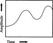
Sound is analog in form by nature—the information or signal contained in the sound are continuously variable as shown in Figure 3-1. Digital signals, on the other hand, are a series of discrete values in which an analog waveform can be represented by a series of numbers. Figures 3-2 and 3-3 show how these numbers, or values, are reached. Having the signal in this form enables us to manage the information efficiently and to process it more easily

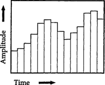
The sampling rate, see Figure 3-2, is the number of times per unit of time (generally this is expressed in seconds) that the amplitude of the analog sound signal is measured. If the series of samples making up the digital signal is taken at a sufficiently rapid rate, the human ear and then the brain cannot distinguish that the signal is not analog in form. This is the same effect achieved by commercial motion pictures. The human eye and brain cannot detect that the image shown on the motion picture screen is made up of a series of still images that are changed at a rate of twenty-four times per second. This corresponds to the sampling that takes place in converting an analog wave form to digital form.
For the satisfactory reproduction of a speaking voice, the digital sampling rate is about 64,000 bits or times a second. At each one of these “times” the amplitude of the analog signal is measured and recorded as a bit separate and distinct from the preceding and the following bits. At this rate, the ear cannot distinguish between these individual bits so the voice is heard as a perfect reproduction.
When recording music however, a much faster sampling rate in necessary to reproduce all of the nuances of the instruments or the singing voice. When recording a CD, the sampling rate is something like 44,100 times a second with 16 bits per sample. There are faster sampling and recording rates on the way, 32 bits. The digital sampling rate for satisfactory voice reproduction is not as high as that required for music.
This is all done by some electronic circuitry, all in one small transistor, that makes up an analog-to-digital (A/D) converter. As each sample of the analog sound is taken, the amplitude of the signal at that moment is measured and the nearest quantization level determined. The nearest digital figure to that level is assigned to that sample. All of this is done, as has been said, at the rate of something like 64,000 times a second for a digital telephone conversation. The process is reversed by means of a digital-to-analog (D/A) converter so that the sound is intelligible to the human ear at the receiver.
Cellular systems, like the landline telephone systems, began operations in the analog mode but are gradually switching to the more efficient digital method that takes up less spectrum space, an important characteristic in today’s increased need for more channels. However, the average user cannot tell which of these systems, analog or digital, is in operation when a call is made.
Having transformed the spoken words in the message into such shape that it can be sent over the air or along the wires of the telephone service, in either analog or digital form, you have to make sure that the message gets to the right party. To do this there are two ways to signal the telephone system and tell it what number is wanted. There is the original rotary dialing system, which generates a series of pulses that indicate the wanted number. This method has been replaced by the Touch-Tone system, which uses carefully selected tones as the identifying signals. The latter is the system used in cellular telephone systems.
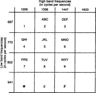
The term Touch-Tone is a registered trademark of the Bell Company and so must be capitalized whenever it is used. The generic term that is used in engineering texts is Dual Tone Multifrequency (DTMF). The DTMF system is based on the simultaneous use of two tones to identify each of the numerals. The tones to be used are selected from four relatively high tones and four relatively low tones. The identification tones are made up in this fashion so that there is no confusion with human speech. The tones generated by human vocal cords are made up of a large number of components that are rarely equal in energy and are far more complex than the DTMF tones. The so-called pure tones generated by the DTMF method are used to tell the telephone system that a signal is being transmitted and that it is not someone singing or playing an instrument. The table in Figure 3-4 shows the two tones that are used for each of the numbers from zero to nine and the two information tones, identified by the asterisk, *, and the pound, #. There is no reason, of course, why other frequencies cannot be added to the matrix so that additional tones can be generated to be used for other functions.
We have brushed over the DTMF system rather lightly, but there is no need to go into great detail regarding the stringent specifications that cover the generation and use of the tones and their transmission. For our look at the cellular and Personal Communication Telephone Systems (PCS), it is sufficient to know generally how the DTMF system works and to realize that it is used in cellular systems. There are other buttons on the cellular telephone handset, but these are controls and switches for the wireless signal that are not needed in the conventional telephone system.
For paging systems, of course, the DTMF system is not used or needed. Rather, a digital identification wireless signal is transmitted throughout the area covered by the paging company. This will alert the wanted pager so that it can respond to the identification signal and receive the message that follows. Because the signal containing the message is coded, it will be received only by the pager with the correct identification.
Now back to the concept that named the cellular telephone system—the cell. The cell itself is an area on the ground that is generally shown as a six-sided honeycomb. This is the simplest way to illustrate the cellular idea; although the actual shape of the cell, and the coverage by the radiated radio signal from the site at the center, will not be as neat and as clearly defined as shown in Figure 1-2. The existing shape of the cell depends on the hills and valleys and on the condition of the terrain such as the size and number of trees and/or the degree of urbanization. All of these factors, in and around the tentative location of the transmitters, receivers, and antennas that make up the cell site, determine how large an area one cell can cover. Some cells are small because a large number of users are concentrated in that area. The need for more channels than can be provided in a single cell means that multiple small sites will have to be installed. Or, it may be the character of the ground that is the main factor. If the terrain is very flat or if the transmitting antenna can be mounted on a tall tower or building, the cells can be larger. As an example, in the Washington-Baltimore area both competing systems cover the densely populated urban areas, the suburbs, and the outlying areas from the beaches on the Atlantic Ocean westward to the forested hills of West Virginia. This region is covered with approximately 300 cells. Most of these cells are located, of course, in the urban areas or along the main highways where the telephone traffic is heaviest.
As has been said, the approximate boundaries of the cells are determined by the terrain and the number of users. This in turn establishes the location of the ground-based radios, control equipment, and accompanying antennas. This location is known as the cell site, and it serves as the link between the subscribers and the Mobile Telephone Switching Office (MTSO), which in turn connects all subscribers to the local telephone system.
With the increase of users in business districts there came a need to provide more capacity in areas where there were coverage problems because of blockage of the wireless signal due to many buildings. So there are now what are called “microcells,” cells with antennas designed to specifically cover these heretofore blocked areas (see Figure 3-5). The signal from these cells can be aimed down a street, between buildings, by the use of specially designed antennas. Or, the antennas can be installed inside such places as airport terminals or sports arenas, where the signal from a site outside these locations could not otherwise penetrate. In some areas there are what are called “repeaters” that receive and retransmit signals. These units are not used to create smaller cells like the microcell, but rather they act only to pick up the signal from a cell site antenna and retransmit it into the area where the original signal cannot be received.

Let’s go back a little and talk now about the type of radio transmission used in the cellular system. It is what is known as a frequency-modulated or FM system. You are probably familiar with this type of broadcasting because it is used for the higher quality transmission from some of the commercial and public broadcasting radio stations. Its static-free, high fidelity quality is important for cellular use, too.
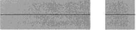
Modulation is the name for the process of adding intelligence to the signal or carrier wave that generated in the transmitting section of the cellular transceivers. The Morse code is a crude form of modulation since information can be gotten from the signal by simply turning it off and on in a predetermined pattern. Figure 3-6 is an illustration of an unmodulated carrier signal from a transmitter, and Figure 3-7 shows this carrier signal turned on and off to form the letter “N”.

A voice signal is not this simple. It is made up of many frequencies and amplitudes and would show a very complicated waveform. For the sake of simplicity, we will assume a simple sine wave such as that generated by a single note from a musical instrument. This could be illustrated by Figure 3-8.

Now, to transmit this note we must impress it on the carrier signal. This is done in the circuitry of the transmitter. The resulting signal can take several forms. The familiar broadcast band, AM signal, would look like Figure 3-9. The AM stands for amplitude modulation—the amplitude of the signal has been changed by the signal that has been combined with it. The amplitude of the broadcast signal varies in direct proportion to the variation of the modifying signal.

In an FM system the information is impressed on the carrier wave in a different form. Rather than the amplitude of the carrier being modified it is the frequency of the signal that is changed. Hence, FM, frequency modulation. An example is shown in Figure 3-10.

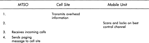
Now that the individual components that make up a cellular system have been described, let’s go slowly through what happens when a call is initiated or received. The description that follows will apply to any of the cellular units—the mobile units mounted permanently in a vehicle, the hand-held portables, or the transportable units that are carried in a shoulder bag or briefcase. All of these units use similar circuitry and software and are only packaged differently.
When the mobile instrument is first turned on, probably by pressing a button labeled “pwr”, it enters what is called the “idle” state. In this condition, it only performs the electronic housekeeping routines that are necessary to prepare it to receive or initiate calls. The logic unit in the mobile handset directs the receiver unit to scan what are called the set-up channels to find the one with the strongest signal. This generally, but not always, turns out to be the one from the closest cell site.
Having found the channel or frequency that gives the strongest signal, the receiver passes that information on to the logic unit. This component directs the receiver to lock onto that frequency and monitor it continuously or until it receives instructions to switch to another channel. At frequent intervals the receiver will rescan the setup channels to see if a different channel will give a better quality signal. The most obvious reason for this, of course, would be that the user has moved into a location where a better signal can be received from a different cell site. If this turns out to be the case, the receiver is directed to switch to the channel with the improved signal.
So far, remember, the user has merely turned on the unit, nothing more. When a call is to be made, the desired number is entered into the instrument in the usual manner where the number is stored in a memory unit or “register” and shows up on the display screen. When the subscriber is ready to place the call the “send” button is depressed. This initiates a signal that is sent over the set-up channel to the cell site giving the user’s ID number, the wanted telephone number, and a request for a voice channel. In addition, the signal tells the billing computer to start charging the customer. Charges begin at the moment the subscriber begins to use the channel even though the connection has not yet been made to the called party.
This information is relayed to the MTSO where a vacant voice channel is assigned to the cell by the switch computer. With a conventional landline telephone system this procedure is not necessary. Merely lifting the instrument from its cradle sends a signal to the system switch that a call is to be made.
The mobile handset receives this new assignment of the vacant voice channel via the cell site transceiver and the logic unit in the handset switches the transceiver to the assigned channel. Meanwhile, the switch at the MTSO completes the call through to the landline system for handling by the local telephone company.
If the mobile unit gets a busy signal, the user touches the “end” button, which has the same effect as hanging up the normal telephone. The desired number is still stored in the register in the handset so the number can be recalled at any time by simply pressing the “send” button again when another attempt to call is being made. The whole process is then repeated.
To place a call to a mobile telephone, the caller dials the mobile unit’s assigned number in the same manner as any other telephone call. This number will be the usual seven digits in length. However, the first three numbers, instead of indicating the area in which the wanted party is located, tell the local telephone system to route the call to the MTSO. This is exactly the same procedure used to route a call to the correct central office over the landlines of the system.
When the wanted number signal arrives at the MTSO, it is checked through the memory in the switch computer and, if recognized and approved, it is matched up with an ID number and sent out to all of the cell sites in the system with instructions to transmit this data on all of the paging channels and, hence, to all of the cellular telephone users. The mobile unit being called recognizes its ID amongst all of the data transmitted on the paging channels as it continuously scans these channels. On another of the set-up channels, the called unit sends its ID to the cell site, which in turn sends it to the MTSO. The MTSO then assigns a vacant voice channel to the unit called. The unit called automatically switches to the vacant voice channel and sends a signal to the cell site that it has made the switch.
The cell site then notifies the MTSO that the connection has been made and that the wanted number has been reached. The MTSO commands the cell site to send a signal over the set-up channel to notify the mobile unit, by the usual ringing sound, that it is being called. This ringing signal is generated electronically, there is no bell in the handset.
When the mobile unit answers the call, the cell site acknowledges that the signaling tone has stopped. The cell site signals this fact to the MTSO, which then connects the incoming call to the mobile unit. The controller also notifies the billing computer to start billing. Originally it was the mobile subscriber who paid the bill whether the call is outgoing or incoming but now there are “Calling Party Pays” programs offered by some carriers that subscribers can sign up for. All of this process, back and forth between the mobile unit, the cell site, the switch, and the local telephone company, of course, takes place in milliseconds and any difference in time between making a cellular call and a regular landline call is barely noticeable.
When the call has been completed and the mobile subscriber hangs up by pressing the “end” button the process is essentially reversed. The transceiver in the mobile unit gives up the voice channel that had been in use and resumes scanning the data channels for another call. At the same time, the cell site signals the MTSO that the voice channel is no longer in use and is free for other users. The MTSO breaks the connection to the Public Telephone Switched Network (PTSN) that had been in use. The total time of the call is recorded against the subscriber and added to the bill that is being compiled in the portion of the computer that handles that particular task.
One of the better ways of presenting what appears, at first glance, to be a rather complicated procedure is by using a table such as that shown in Tables 3-1 and 3-2. These were taken from an OKI Telecommunications publication. Remember that all of these actions take place in milliseconds.


There are restrictions that can be placed on a mobile telephone by the individual subscriber or by the user’s company if it is a company telephone. Arrangements can be made to have the mobile unit “receive only”; outgoing calls cannot be made. In reverse, “outgoing only” can be installed on a unit where it is not necessary to receive incoming calls.
What happens when the mobile or portable unit begins to move out of range of the signal from the original cell site while in the middle of a call? This is not an unusual situation at all considering that normal cells vary in size from one and one-half to five miles across and a mobile unit in a vehicle moves from one side of town to another.
As has been said, the strength of the signal on the voice channel that is being used between the cell site and the mobile unit is being constantly monitored over the data channel and compared with a standard level of strength. When the signal gets weak and goes below the established standard, the MTSO switches the call to a vacant channel that will give a better signal either in the same cell site or in an adjacent cell site. At the same time, the cell site is directed to tell the mobile unit to switch to the newly assigned channel. The mobile unit does this automatically and the MTSO checks to see that the transfer has taken place. This procedure is called a “hand-off” and is accomplished without either party being aware of what has taken place. The recently introduced PCS services operate in generally the same manner except that they will be on a much higher frequency, 1,900 MHz instead of 800 MHz.
There is little doubt that the development of the cellular mobile radiotelephone system would not have been possible without the evolution of the computer and the necessary software to operate it. This wonder of the electronic age has become such an integral part of our lives that we have come to accept it and tend to forget how we got along without it.
The use of this capability has become so pervasive that the lines of definition have become somewhat blurred. Just what is a computer? Can you call the little black box in your automobile that monitors the temperature of the coolant in your radiator a computer? This device measures the temperature of the coolant and when the temperature reaches some set limit, it turns on the cooling fan. When the temperature goes down again, the computer turns the fan off. This device certainly monitors and controls one of the many variables in the operation of your automobile. How about the controls of your microwave oven? The device will turn the oven on and off at predetermined times and can monitor and control the cooking of a roast by means of a probe.
These electronic devices are called dedicated units. This means that they are designed to perform one particular task only and cannot be reprogrammed to do anything else. The set of instructions, or program, that the unit is to follow is designed into the unit, unlike the personal computer sitting at home in the study or in the living room. The personal computer can be programmed to do many things, and the shelves of computer stores are full of many different software programs for it However, when one of these personal computers is installed and made part of a system and programmed to do only one job and nothing else, it is then considered a dedicated computer. The same term applies to a telephone circuit or line that is used solely for one particular purpose, the line becomes a dedicated line.
You will recall that we talked a little about the characteristics of the technology that permitted the reuse of the frequencies in a cellular system. A rule of thumb in the industry, based on experience, states that a channel can be reused again in every seven cells. The application of this rule will vary tremendously, of course, since there are so many factors that will affect the propagation of the radio transmissions. The particular terrain, the degree and density of urban growth, the expected number of subscribers—all of these things will determine the size of the cell. The decrease in the price of the cellular telephones and the intense competition between the systems has led to a great growth in the number of users. In addition, additional uses have been found; the use of portable fax machines, portable printers, and laptop computers in conjunction with the cellular telephone is not unusual nowadays.
Since the system operator cannot add channels to the system—each system is limited to 333 channels—a technique called channel splitting has been devised. This technique is demonstrated in the examples illustrated in Figure 3-11. The area is covered by the usual seven cells, which are shown in the conventional honeycomb shape with an antenna located in the center of each cell. This situation never happens in real life—it is never as neat and tidy as this anywhere—but this example illustrates the technique involved.

By changing the antenna design in one cell so that the radiated energy is concentrated in an arc of 120 degrees rather than the complete 360-degree circle used formerly, the number of cells can be increased (see Figure 3-11). Using this technique the same cell site can probably be used. Only the antennas have to be changed, additional equipment installed, and computers instructed to handle the additional load. This can be carried on again and the original seven-cell system could end up with twenty-one cells. In addition, there is the use of microcells and repeaters for specific situations that has already been mentioned.
None of this cell splitting or installation of microcells or repeaters can be done without extensive testing and engineering studies. One of the tasks of the computer at the MTSO is traffic analysis, enabling the system manager to determine subscriber needs and changes well in advance so that the necessary tests and studies can be carried out. While the cellular equipment is not “far out” in terms of design and construction, it cannot be purchased off-the-shelf at the neighborhood electronics shop. It takes time to analyze data, make necessary engineering studies, and design and install the original equipment as well as develop the information, when needed, to give a desired increase in subscriber capacity.
All of the equipment that has been described so far has been designed and installed to keep the system working efficiently and the customer happy when operating in the local or home area, which is served by the local cellular system operator. When the subscriber drives outside the home area and beyond reach of the coverage by that one particular system, the home system, it may be another story.
The term “roamer” is used by the industry to describe a subscriber who “roams” outside the area covered by the home carrier, the area assigned by the Federal Communications Commission (FCC), and into an area covered by another system. Driving through the more densely populated areas in the country, the Washington-Boston corridor is one example, the traveler can connect with the several systems covering that well-traveled area. A subscriber to one of the two Washington area cellular systems, for example, can pick up the cellular handset in a vehicle anywhere along the New Jersey or Connecticut Turnpikes and make a connection through the system that has jurisdiction and, therefore, has located cell sites in that area.
With conventional wireline telephone systems, the problem of making a call from the area covered by one of the regional companies to another area is taken care of by any one of a number of long distance service providers. Each of the seven regional telephone systems, the Baby Bells, that cover the country since the breakup of AT&T, are obliged to provide the local connection for any of these long distance companies. This may change in the coming years when the 1996 Telecommunications Bill takes full effect.
Roaming agreements are in effect between practically all of the cellular operators, and the early problems encountered when trying to make or receive cellular calls when outside your home area have been greatly reduced. Procedures necessary to make and receive calls when traveling vary from one carrier to the next, and the procedures are changing as new agreements are reached between carriers. If you plan to use your cellular telephone when traveling it would be wise to make sure that you know your carrier’s latest arrangements for making and receiving calls when roaming. The billing for the calls you make when roaming in another carrier’s area will probably be on your regular monthly bill. Coordination of these billing arrangements is handled through a subsidiary of the industry’s trade association, the Cellular Telephone Industry Association.
In addition to the normal ground-based cellular services, a dual-mode satellite/cellular system is being introduced. When a call is placed with the specially equipped handsets, the cellular system first searches for an available conventional cell site to put the call through. If no such system is available, the call will be transferred automatically to a satellite and relayed to a ground station, then to the MTSO, the PTSN, and to the called party.
In addition to the dual-mode handset, users of this system will need a satellite transceiver and a small dome antenna that is mounted on the roof of their vehicle. The system will also include facilities for the use of facsimile and data messages. Billing for use of this service will be done by the user’s home cellular carrier. The monthly statement, in addition to showing normal cellular air time and roaming charges, will include charges for satellite usage and the monthly satellite system access fee.
Technology is making it possible for the cellular system to be more than just a telephone service. Some cellular systems are offering a combination service of paging and telephone access. In this case the cellular handset can be treated like a paging unit with a short message displayed on the screen. There is also voice mail service available for those times when the cellular telephone cannot be answered.
To add to the flexibility of the cellular telephone, it is possible to connect the cellular handset to a portable or laptop computer. This means that you can call into the local landline telephone system just as you do with the PC in your office or at home. With a PC you install a modem, internally in an expansion slot in the computer or externally as a separate piece of equipment sitting on the desk and connected to the computer with a cable. Then you connect the computer or external modem to the local telephone service and either share the line with the office or home telephone, or if you use this feature a lot you can have a separate line installed.
The modem, MOdulator/DEModulator, is a unit of electronic circuitry that transforms the analog sound signals that come over the telephone, either through the wires of the local telephone system or transmitted by a cellular carrier’s cell site transceiver. The modem converts the sound into a stream of data bits, digitizes it in other words, so that the information is understandable to the computer. The modem also works in reverse, reconverting the data bits into the sound signals that are acceptable to the telephone system and understandable to you.
For use with a cellular telephone and a laptop computer, the modem comes in the form of a credit card-sized accessory called a Personal Computer Memory Card International Association (PCMCIA). This organization is responsible for the standards and specifications of these devices. The card slips into the PCMCIA slot in the laptop computer and connects to the cellular handset with a cable. Now you can go on-line to send and receive e-mail, to get stock quotations from one of the business services, or to download information or communicate with other workers in the office local area network. Or, you can unplug the computer and connect to a portable fax machine or printer and receive office memos on the run. This will give you a complete mobile office with all of the capabilities of the fixed office that so many of us are used to.
Paging systems are somewhat simpler than the cellular ones. Messages can be sent out in a number of ways. A verbal message can be given to someone in the paging company office who will send it out by means of a keyboard or computer to the transmitter. If the volume of messages is great enough, arrangements can be made to make a direct connection to the equipment originating the pages. Messages can then be sent out and acknowledgments received directly.
Paging units come in a bewildering variety. There are the very simple and inexpensive models that merely alert the user with a beep and display a telephone number to be called. There are those pagers that can return a call by pressing a button that will send preselected messages such as “message received” or “will call,” for example. Others are equipped with somewhat larger screens and can receive longer alphanumeric messages, some up to 256 characters in length, and more elaborate models have an alphanumeric keyboard that can be used to answer a message.
One recently developed use for pagers is the ability for hospitals and doctors to transmit electrocardiograms (EKGs) to mobile cardiologists. The system consists of a personal computer situated in an emergency room, for example, loaded with the software to prepare the data file, which could be an EKG reading, and then transmit it to a pager network for wireless transmission. The receiving end of the system is the doctor’s pager, which is connected to a palmtop or laptop computer through a special link that prepares the data for display as an EKG on a high-resolution screen.
Further up the scale, there are what can be called “wireless communicators” that have screens nearly as big as a laptop computer. They can receive and send text and graphics anywhere within range of a system’s transmitter. There are now paging systems that use satellites for transmission and reception of signals from almost anywhere in the world.
All paging system signals are digital in form and, therefore, can transmit only alphanumeric characters or data. There can be no voice communications. When a verbal message is given to a paging system operator, the message is converted into the digital form by typing it on a keyboard. Then the message, in digital form, is combined with the desired recipient’s ID information and transmitted.