Mobile Communications
In very general terms, the preface told a little about paging systems, the original cellular mobile radiotelephone system, and the Personal Communications System (PCS) or service, the newer type of cellular system that is just getting off the ground and into the air. These two are generally lumped together now and are referred to as just cellular telephones. The preface also mentioned what these paging and cellular telephone services could do for business people and the general public. The chapters that follow will explain each part of these systems, explained in more detail, although not enough to enable you to build and maintain your own service but, it is hoped, enough to help you understand the technology that has made such a difference to our social and business lives.
These wireless communication systems take place in a small portion of what is known as the electromagnetic spectrum. These two words describe the entire range of electrical and magnetic wavelengths or frequencies that extend from the audible frequencies or sound waves up though the radio frequencies, then through visible light, to x-rays and the gamma rays. The illustration in Figure 1-1 shows very roughly how the radio or wireless portion of these frequencies is divided up. Only those portions of the spectrum that are of interest to us and the topics that we are going to discuss are shown. Not shown are the locations of the hundreds of other users of this scarce natural resource, AM and FM radio broadcasting stations, TV stations, amateur radio, marine radio, the police and fire services, the medical profession’s many instruments and monitoring devices, and other services too many to mention. All of these take up a portion of this valuable finite spectrum. The limits are fixed, this resource cannot be stretched or enlarged for additional users no matter what we do.

Figure 1-1 The electromagnetic spectrum showing those portions of interest emphasized. (Courtesy The Bishop Company)
Each wireless signal takes up an assigned portion of the spectrum, a number of frequencies or what is sometimes called a channel. For example, one analog cellular telephone signal is given 30 KHz (.03 MHz) of the approximately 150 MHz that are assigned to the cellular service. This is because the human voice, when transmitted in analog form or just as spoken, covers a fairly wide range of frequencies. Note that some of the frequency bands are given to what is called “wide-band PCS,” the coming new personal communication systems. Any narrow-band signal, “narrow-band PCS” for example, is used for the transmission of data in digital form, which only takes up 10 KHz. The paging systems are another example of a narrow-band signal. The difference between an analog and a digital signal, and the effect that this difference makes, will be explained in a later chapter.
Let us look first at paging systems. This method of communication probably got its name from a custom that was common in hotels before a telephone in each room was standard. When a message was received for someone in the hotel, a uniformed bellboy would be sent to the guest’s room with the message. If the guest was not in their room, the bellboy would go through the hotel lobby or restaurant and call for, or “page,” the wanted person.
Paging systems have come a long way since the introduction of the first units that merely beeped to alert the individual wearing the pager to call a predetermined telephone number. There are now some 2,000 paging systems scattered across the United States with more than 20 million users. Today, pagers are just one part of what is known as the wireless data industry or field. The term, wireless data, refers to the radio transmission of text or numeric information in digital form and generated and entered into the wireless system by a separate dedicated keyboard or perhaps a desktop or personal computer. But, and this is important, wireless data does not handle voice communication.
Wireless data is a vast and growing field that is not usually familiar to the general public. It includes, among a host of other uses, such technologies as computer terminals in police cars that are capable of performing a wireless driver’s license and vehicle registration check using the headquarters computer memory, without the need for a verbal request made on a police voice channel.
UPS and FedEx package deliveries are verified when the bar code on the label of a package is scanned into the driver’s handheld unit as it is delivered and signed for. This unit is then slipped into a holder when the driver returns to the vehicle. The holder, which then reads the data from the scanning unit, is connected to a radio transmitter on the vehicle that is programmed to periodically send the delivery confirmation data that has been collected to a wireless receiver at the delivery service headquarters. It is then sent to a computer storage memory for reference in case delivery verification is needed.
When a department store sales clerk slides a credit card through a reader to verify customer status, the data imprinted in the magnetic strip on the back of the card is sent to a central credit bureau for approval. In some installations this data is sent back and forth via a wireless data system. None of these uses need the human voice to convey the needed information.
A paging unit does not have to perform all of the functions of a cellular telephone and so it can be somewhat smaller and simpler. Some page receiving units, the beeper, are small enough to be carried in a shirt or blouse pocket, or they can be clipped to a belt, handbag, or briefcase strap. There is one paging unit that has been incorporated in a wristwatch and another that is modeled after a fountain pen. All these smaller units have to do is to alert the user with an audible signal such as a beep or, in some models, by a silent vibration, to the fact that a message is being shown on the unit’s small screen. Some pagers have increased capabilities allowing users to acknowledge that the message was received. Other pagers can initiate a message, using a small keyboard, that is transmitted back to the paging system’s headquarters. With a paging system there is no need for the constant back-and-forth transmissions that go on between the cellular telephone system transmitter at the cell site and the user’s handset to maintain satisfactory contact.
The radio transmitter of a paging system uses an assigned frequency, in one of several bands, for sending out a signal. The transmitter can be a fairly high-powered unit with sufficient energy to cover an entire city or metropolitan area or, if the area is too large to be reached with a single unit, multiple transmitters and antennas can be installed and used to simulcast the signals over the desired area. Some paging systems are designed to use what is known as the subcarrier frequencies of a commercial FM station that broadcasts in the desired area. At present, there is at least one commercial paging system that covers the entire continental United States and some foreign countries by using communication satellites to receive and then retransmit the alerting radio signal. Other similar systems are on the way as the need for transmission of this type of data grows.
If coverage of a large area, such as an entire town as has been described in the previous paragraph, is not required, a single, low-powered transmitter can be used. This system will provide service for perhaps one office building or a group of buildings such as a large hospital complex, a university campus, a shopping mall, or a department store. Now there are paging units that can be connected to a laptop or a desktop computer through a specially designed interface to receive and display, on the computer screen, much more data than can be shown on the rather small display area of a typical pager. One typical use for this sort of arrangement, which would not require any response from the recipient, would be the receiving of large amounts of text material such as an updated price list for a salesperson or perhaps a revised list of customers to be visited.
In comparison to paging systems, a cellular telephone system uses a network of relatively low-powered radio transmitters and receivers that cover an assigned city or town and the surrounding area. This network is made up of a number of cells, each with a combined receiver and transmitter called a transceiver at the center. Along with the transceiver is an antenna that radiates the wireless signal to and over the desired area. This is called the cell site and the size of a cellular system is judged by the number of such sites.
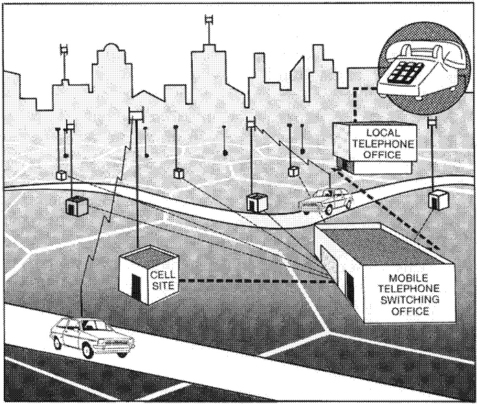
Each cell and its transceiver, antenna, and controlling equipment acts as a relay and interface between the user’s cellular telephone handset, which is also a transceiver, and the local telephone company. When the mobile handset is turned on by the subscriber, the cellular system begins to constantly monitor the strength and quality of the “housekeeping” radio transmissions to and from the mobile handset and the various cell sites of the system. As the user moves around the area, the system automatically shifts the connection, if necessary, to the cell site that will provide the highest quality communication channel. This is all done with some rather sophisticated electronics and computer programming. The cellular concept is shown schematically in Figure 1-2. In most systems, the Mobile Telephone Switching Office (MTSO), which is part of the cellular system, is simply called “the switch.” The local telephone company that provides the final connection to the desired telephone number is usually referred to as the Public Telephone Switched Network (PTSN).
Late in 1994, the Federal Communications Commission (FCC) began action to auction licenses for another form of cellular telephone service that has become known as Personal Communication Service or, more generally, PCS. This service has been assigned frequencies in the 1900 MHz section of the spectrum, the original cellular systems operate in the 800 MHz area, and the first PCS carrier went on-line in the Washington/Baltimore area late in 1995. The new PCS service has also been discussed by some in the industry as a combined cordless and cellular telephone. This means that the user has the convenience of a single telephone number and can be reached or can make calls no matter whether they are in the backyard or in their car miles from home.
When the cellular telephone systems were first being introduced to the public there were many ads in newspapers and magazines, especially those catering to the business community, demonstrating the ease with which telephone calls could be made from a car, the golf course, or from beside the swimming pool. It is still true what the ads have said—making a telephone call from a vehicle or from your hand-carried unit to anywhere in the world is as simple and easy as making one from your home or from a pay station in the street. With the addition of a small accessory interface unit, similar to that mentioned for use with pagers, cellular telephones can be linked to laptop computers, portable fax machines, or to portable printers so that users can go on-line anywhere to send and receive information and data and even so that they can browse the Internet.
Naming the cellular system as such was rather obvious since the service area is divided into a number of cells, generally shown in a honeycomb fashion. The actual radio coverage of the cells is rarely as neat and well-defined as shown in the illustrations because of the effect of the surrounding terrain and/or building density. The equipment at the cell site, the radio transmitter/receiver or transceiver, the control equipment, and a set of antennas, is connected by a dedicated telephone line or microwave radio relay link to the central switching and master control unit, the MTSO, which as you will recall, is the interface with the local telephone company.
Each of the cells uses a group of radio frequencies or channels that are sufficiently removed, higher or lower, from the frequencies in use in the adjoining cells in order to avoid signal interference. Since the number of available frequencies is limited by law and is assigned by the FCC, efficient use of that portion of the assigned radio spectrum requires that the frequencies be reassigned and reused by other cells located at a sufficient distance to avoid this interference. Generally, this turns out to be every five to seven cells. Figure 1-3 illustrates this arrangement. This frequency reuse is one of the major factors in the success of this cellular system and was a major advance over the older mobile radiotelephone systems. Many more users could be accommodated with this arrangement.

The signal coverage from the radio transceiver at each of these cell locations is the governing factor in determining the size of the cell. In an area with relatively flat terrain and no obstructions to the signal, like some of the cities in the Midwest, the cells can be much larger than the cells in an area with many hills and valleys such as Johnstown, Pennsylvania, or San Francisco. In one of the two present 800 MHz systems covering the Washington-Baltimore area, for example, there are some 300 cells in the system covering more than 13,000 square miles. One of the advantages of the cellular system is that, if the number of subscribers in one area of the system becomes too large to be handled efficiently by the available channels in the existing cell, the cell handling this overload of traffic can be divided into smaller cells.
The type of radio transmission used for this mobile telephone system is the same as that used for high-quality commercial radio, FM. This essentially static-and-interference-free method of communication makes available in cellular radios the “you-could-be-in-the-next-room” quality found in FM radio. Originally designed to handle the voice in what is known as an analog system, similar to that used in the conventional wired telephone system, cellular carriers are upgrading to a digital system. The big differences will be discussed in Chapter 3, but for now it is enough to say that the digital signal takes up less space and allows more efficient use of the wireless spectrum.
When people start looking for answers to the question, “Why is a new mobile radiotelephone system needed?” they tend to become overwhelmed with numbers and statistics. Now we will wade through some of the history and rough figures that are available to get an idea of the magnitude of the problem that faced the telecommunications industry in their attempt to meet the mounting requirement for a more efficient mobile service.
Prior to the introduction of the cellular concept, the existing mobile radiotelephone services were designed around the use of a single, high-powered base station serving the needs of the mobile units in an entire city and the surrounding areas. This is similar to a paging system described earlier. A conventional commercial radio or TV station also serves its customers in much the same way. The number of customers that can be served by the mobile wireless service or the radio/TV station depends, in general, on the location and height of the antenna and the amount of power that can be radiated from it. This sort of system meets the requirements of such services as taxis and package deliveries.
With a service of this type, reliable communication with a mobile user is possible within a radius of about 20 miles of the antenna (covering about 1,300 square miles). But the radio signal from the base station, even when not strong enough for satisfactory communication with mobile stations outside of the covered area, would still have sufficient power to interfere with the other radio signals of similar services on and around that same wireless frequency within a radius of about 100 miles.
With this single base station concept, the limitations on the number of frequencies available, and former radio communication techniques, there were only about 25 voice channels usable at each station. This meant that in New York for example, certainly one place in the country where rapid and constant communications are considered a necessity for the financial and corporate community, only about 700 customers could be accommodated. Like the rest of the country, with this older system these 700 customers could complete only 50% of their calls at the first attempt. It is easy to see why the marketplace was ready and impatient for an improved service.
In 1978, after twenty to thirty years of experimenting, developing, testing, and then briefing the regulatory agencies, and submitting the paperwork needed to get the necessary radio frequencies assigned, the first cellular mobile radiotelephone system was commercially tested in Chicago by AT&T and its former subsidiary, Illinois Bell. This was approximately thirty-two years after the introduction of the first commercial mobile radiotelephone service in St. Louis.
Around the country at that time there were about 40,000 AT&T customers with mobile telephones and, as we have said, these customers had about a one chance in two of completing a call on the first attempt. In addition, there were about 20,000 unhappy potential customers with their names on waiting lists to get mobile service, with an expected wait of five to ten years, because of the limitations of the system and equipment then in use.
This brief touch of history shows why the pressure was on the telecommunications industry to get an improved system into operation as quickly as possible. The new mobile radiotelephone system was brought into reality by the same technology that led to the development of calculators the size of a business card, computers of incredible power that can sit on your desk, and the electronic monitoring, control and display of many of the essential operations of the automobile.
The concept of a cellular system had been talked about at AT&T Bell Labs as early as the 1940s, but the system was not really feasible with the state of technology at the time. Radio equipment of all types was designed around the vacuum tube with its requirement for large amounts of electrical power for operation and for the cooling needed to get rid of the subsequent emission of considerable heat. Computers at that time were filling huge rooms with racks of vacuum tubes, relays, power supplies, and the other needed accessories. The programming of these primitive monsters was in its infancy and still depended on the use of punched cards, a descendant technique coming from the rug weaving industry, to get the information in and out of the computer.
The end of all this came in sight in 1947, again at Bell Labs, with the invention of the transistor, a tiny replacement of the vacuum tube. This transistor needed much less power to operate and so this led to a great reduction in the size of all of the components and, therefore, the completed equipment. This resulted in a tremendous increase in the speed of operation of the electronic systems using these new transistors.
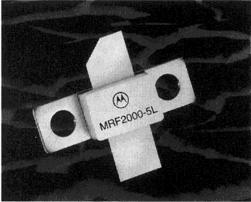
At first, wireless engineers and circuit designers treated the transistor simply as a replacement for the vacuum tube in the electronic circuits. They continued to use the other necessary components (the resistors, capacitors, and coils needed to make the circuits work) as individual and separate items. However, as time went on the engineers learned more and gained experience with the new technology and materials. They found that they could achieve the same results by etching or plating various materials on a copperplated sheet of synthetic material such as fiberglass. These circuits would act in the same manner as the previously-used individual components that had to be hand- or machine-wired together. Now the entire circuit could be greatly reduced in size. Circuit boards, with a multitude of components that used to be handled individually and measured in inches on a side, could now be measured in tenths of an inch. What once took up a whole chassis and fitted on a standard 19-inch electronic rack and panel, could now be put on an easily handled circuit board. Figure 1-4 is a greatly enlarged photograph of a Motorola transistor. This chip contains the components and circuitry to amplify a radio signal to a maximum of about 9 watts and to control the amount of amplification as instructed from a control unit. The longest dimension of this transistor chip is a little over three-fourths of an inch. Now the necessary control knobs and switches of the equipment became the size-limiting feature—they had to be large enough to be easily handled by human fingers.
Because of this great reduction in size of the electronic components and circuitry, there was a reduction in the length of time that it took the electronic signals to traverse the circuitry. Despite the common impression that electricity travels at the speed of light, it takes a finite length of time for signals to travel from one end of a circuit to the other. If this time could be reduced with solid state electronics, as it was significantly, then the circuit could accommodate more signals that could move at a faster rate.
A particularly important feature for the wireless engineers, as well as for the telephone industry, was the fact that equipment and techniques were developed so that signals could be switched electronically from one circuit to another. There was no need now for any mechanical movement whatsoever, no more clicking relays to do the multitude of switching functions necessary in an operating telephone system.
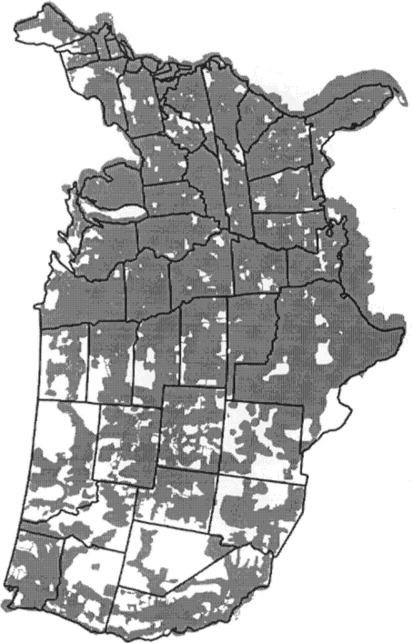
The following developments all came together at the same time: the microcomputer, the computer on a chip, and the increasing experience and skills of the computer programmers; and the electronic switch mentioned above. All of these things not only improved the efficiency of the existing landline telephone system but also made the cellular radiotelephone system a practical, realizable goal. At the end of 1995, after twenty years of service, cellular telephone system coverage in the United States was as shown in Figure 1-5.