2
the LEGO-compatible laser
Lasers fascinate people, and they’re useful too; you can use them to project a beam over a long distance, make animated light shows, measure distances, experiment with the wave nature of light, and create holograms. It’s natural to want to add a laser to LEGO inventions. Unfortunately, LEGO doesn’t offer a LEGO-mountable laser, probably because of the safety issues discussed in the following box.
In this chapter, you’ll build your own LEGO-mountable laser to use in future projects. This laser will use a LEGO-based battery source, so you can incorporate the power supply into your LEGO contraptions as well.
the diode laser module
To build the LEGO-Compatible Laser, you’ll need a diode laser module (Figure 2-1), which includes a diode laser, along with a current-control circuit and a collimating lens.
Diode lasers are small devices, capable of producing bright beams, that are often used in CD and DVD players and laser pointers. The module’s current-control circuit keeps the power output of the laser at a constant level. Otherwise, if the electrical power to the laser changed, the output of the laser could get too high, posing a safety hazard or burning out the laser, or too low, creating a beam too dim to be useful. This circuit also protects the laser in case you accidentally reverse the positive and negative connections. This particular laser module has control circuitry sticking out the back, but some devices keep the circuit inside the cylindrical enclosure. The collimating lens controls the divergence of the laser output to generate a narrow beam. Some laser modules have adjustable lenses to set a specific focus or divergence.
Some lasers, like the one shown in Figure 2-1, also come with stickers to place on the laser’s future housing as a safety warning.
You can purchase diode laser modules at many places on the internet, including Digi-Key Electronics (https://www.digikey.com/), Newark (https://www.newark.com/), Jameco Electronics (https://www.jameco.com/), and Mouser Electronics (https://www.mouser.com/), for about $49. I recommend the Digi-Key VLM-635-02-LPA-ND, but the directions in this chapter are flexible for different devices.
Also keep in mind that jolts of static electricity can destroy diode lasers. If you find yourself picking up a lot of static in your home, touch something metal (for example, a doorknob) before working with the diode laser module. When you finish the module, it’s a good idea to keep the completed module in the static control bag the laser comes in, so save this bag.
what you’ll need
You’ll need LEGO bricks to serve as a housing for your diode laser module. Figure 2-2 summarizes the bricks needed. None of these parts, except for 2780 Technic pins, are part of the MINDSTORMS EV3 #31313 set.

FIGURE 2-1: The diode laser module includes control circuitry, a collimating lens, and wire leads.
In addition to the LEGO bricks, you’ll need the following components:
Diode laser module (such as Digi-Key VLM-635-02-LPA-ND)
Zener diode for the laser module (You can use 1N4733A for the diode laser module in this list, or for another laser module taking a 5V input.)
47 ohm, 1/2 watt resistor
9V battery
Sugru moldable glue (one 5-gram single-use pack)
Cyanoacrylate glue such as Super Glue, Krazy Glue, or Gorilla Glue (a few drops from a small tube)
You’ll also need the following tools:
Drill (I used a small cordless hand drill, though a drill press would be ideal if you already have one.)
Drill bit (whose diameter is less than that of the diode laser module, usually about 6 mm or 1/4 inch)
Tapered reamer of 3 mm (1/8 inch) to 12 mm (1/2 inch) capacity
Soldering iron and solder
Vise
Diagonal cutters
Wire strippers

FIGURE 2-2: LEGO parts used to build the LEGO-Compatible Laser
mounting the laser module
To incorporate the diode laser module in LEGO creations, you need to mount it in a LEGO part. You’ll use a Technic gearbox, shown in Figure 2-3, to hold it.
Gearboxes typically hold a worm gear against a conventional gear to drive the wheels of a vehicle, but the placement of its holes and its hollow lower portion are ideal for housing the diode laser module, as shown in Figure 2-4. Two gearboxes, held together with Technic pins, are used here to accommodate the full length of the diode laser module.
If you need more than two gearboxes, you can add a third one by using the process described next.


FIGURE 2-4: Two gearboxes joined together to house the length of the diode laser module
drilling holes in the gearboxes
The gearboxes need modification to accommodate the laser module. Specifically, you need to drill out their uppermost center holes because their diameters are too small to fit the laser module. Drilling into plastic can be a little difficult, because the plastic tends to grab the drill bit, so it’s a good idea to anticipate problems and buy several spare gearboxes. The drill bit for the job should be smaller than the diameter of the laser module. The diode laser module in Figure 2-1 has a diameter of 10 mm (2/5 inch), so I used an 8 mm (5/16 inch) drill bit.
The hole to enlarge with the drill is in the center, upper half of each gearbox. Use the existing LEGO-sized hole as a guide for the bit, as shown in Figure 2-5.
Since the laser module will go through both sides of each gearbox, drill through the hole on both sides. To keep both holes aligned, you should drill them from each side, rather than drilling on only one side and punching through the other end. Doing this would likely knock off the centering of each hole with respect to the other, because it’s difficult to hold the drill straight and perpendicular through both holes.
If you have a drill press, you can use it to hold the bit straight and perpendicular to the gearbox hole. If you don’t have one, a hand drill works fine, as long as you hold the drill perpendicular in a vise, as done in Figure 2-5. Don’t try to hold the gearbox by hand when drilling, since it will spin out of control.

FIGURE 2-5: Carefully hold the drill bit so that it is straight and perpendicular to the gearbox.
rounding out the holes with a reamer
The holes you create will probably look messy and not quite round, with bits of plastic still clinging onto the rim. Use a reamer, shown in Figure 2-6, to clean up the holes and enlarge them to just the right size.

FIGURE 2-6: After drilling the holes, widen them by twisting a reamer through them.
Reamers come in different diameter ranges. The one to use here has an upper diameter of 12 mm (or 1/2 inch). Ream the hole a little at a time, stopping frequently to compare the hole’s diameter to the diameter of the diode laser module.
Gradually open up the holes on both sides until the cylinder of the diode laser module fits snugly inside, as shown in Figure 2-7.

FIGURE 2-7: The diode laser module should fit snugly inside the hole.
The second gearbox (or third, if you need it) also needs to be drilled and reamed.
powering the laser module
To use your LEGO-Compatible Laser, you have to attach it to a power source. Most diode laser modules take input voltages of 3V to 6V. Unfortunately, the standard LEGO electric battery boxes have outputs of 9V, which isn’t compatible with the laser module. (LEGO made a 4.5V electric battery box in the 1960s and 1970s, but these old modules are hard to find in good condition, and they’re quite large.)
To connect the battery box to the laser module, you’ll modify the battery box with a few electrical components.
modifying an electric wire cable
The electric wire cables come in lengths ranging from 15 studs to 378 studs. The last few digits of the part number indicate the length in studs (where Figure 2-2 shows xxx). For example, 5306bc015 describes a wire cable that is 15 studs long. Choose a length based on how far you want your battery box to be from your laser. In Chapter 3, we’ll conduct an experiment in which the diode laser module can be quite close to the battery box, so a short cable, such as the 5306bc036, should work fine.
Connect one end of the cable to the battery box. These cables contain two wires, a positive one and a negative one, side by side, so it’s possible to keep track of which side of the cable is attached to which side of the battery box. In the orientation shown in Figure 2-8, the cable connector is attached so the wires are opposite the switch, and the right side of the box is negative and the left side is positive. That means the right-side wire is negative, and the left side is positive.
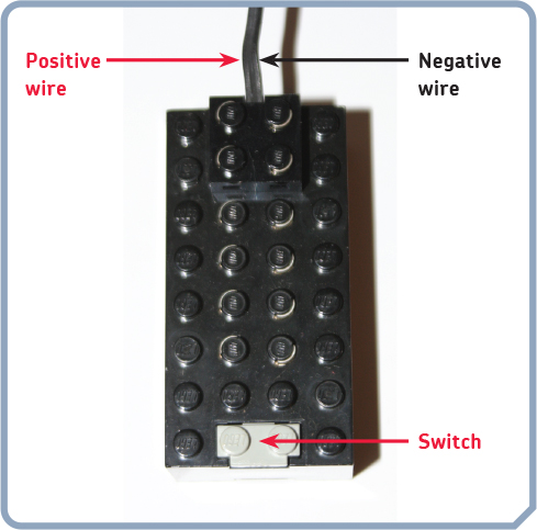
FIGURE 2-8: A 9V battery box (4760c01) with an electric wire cable (5306bc) attached in this orientation has the positive connection on the left side and the negative connection on the right side.
Next, cut off the LEGO connector on the other end of the cable—the end without the switch. This end has to be reduced to bare wires in order to be connected to the laser module. Clip off the LEGO connector on the laser end, as shown in Figure 2-9a. Then separate the two wires with diagonal cutters, as shown in Figure 2-9b. Using wire strippers, as shown in Figure 2-9c, expose the bare metal wire of both ends.
You can now thread the bare-wire end of the cable through a bottom, side hole of the rearmost gearbox, as shown in Figure 2-4. You’ll attach it to the laser in a later step.
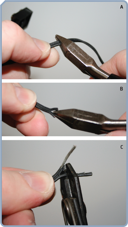
FIGURE 2-9: Preparing the end of the wire cable for connection to the laser module
connecting the Zener diode and resistor
In order to step down the 9V from the LEGO battery box so it’s in the 3V to 6V range that the laser needs, you’ll use a Zener diode and a current-limiting resistor (Figure 2-10).

FIGURE 2-10: The Zener diode is the smaller device with a black band (left), while the resistor has multiple colored bands (right).
A Zener diode creates a constant-output voltage from a higher-input voltage when reverse biased. Reverse biasing a diode means intentionally hooking it up backward. Using the Zener diode to connect the battery pack to the laser in this way will put the voltage in the proper range. Zener diodes come in different voltage outputs, so select a Zener diode that matches the voltage of the diode laser. For example, the IN4733A Zener diode has an output of 5.1V that fits within the voltage range that the laser diode module needs.
But if you connected the Zener diode to the power source by itself, it would consume all the electrical current the source could produce and likely burn out. Just as you have to limit the amount of food given to a pet goldfish, you have to limit the current so that the Zener diode won’t eat its way to self-destruction. To do this, you’ll place a resistor in front of the diode. Be sure to get a resistor with the 1/2 watt power rating, as opposed to the also-common 1/4 watt variety. A 1/4 watt resistor used here could possibly melt, causing the entire circuit to fail.
The circuit to put the diode and the resistor together is drawn in Figure 2-11.

FIGURE 2-11: Use a Zener diode to step down the 9V from the LEGO battery box to a suitable voltage for the laser diode module.
To implement this circuit, you have to do a little soldering. If you don’t know how to solder, video tutorials on YouTube (https://www.youtube.com/) and SparkFun Electronics (https://www.sparkfun.com/) can help. You can buy the soldering iron and accessories at SparkFun and Jameco. You need to make three solder joints, pictured in Figure 2-12, and then trim the leftover lengths of the wire leads.
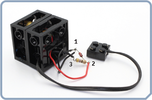
FIGURE 2-12: Three solder joints connect power to the laser diode module.
Before soldering, make sure that the wire cable from the battery box passes through a bottom, side hole of the gearbox and that the two wires from the laser module travel down through the bottom, back of the gearbox. Later, you’ll tuck the soldered joints and Zener diode circuit into the bottom of the gearbox.
The three solder joints you need to make are as follows:
Solder joint 1 Three leads consisting of the negative lead from the LEGO battery box, the black lead of the laser module, and the anode end of the Zener diode. The anode end of the Zener diode is the one without the black band. Anode is a term to describe the electrically positive end of an electronic component. But remember that a Zener diode is intentionally hooked up backward, so the anode of the Zener diode goes to the negative end of the battery.
Solder joint 2 Three leads consisting of one end of the resistor, the red lead of the laser module, and the cathode end of the Zener diode. The cathode end of the Zener diode has a black band around it. The cathode is the opposite end from the anode, corresponding to the negative end of an electronic component, except in the circuit used here with the Zener diode being used in a reverse bias. Resistors have no polarity, so it doesn’t matter which end of the resistor you use for this step.
Solder joint 3 Two leads, consisting of the end of the positive lead from the LEGO battery box and the other end of the resistor.
After you’ve trimmed away the excess lead wires to look like Figure 2-12, it’s time to light up the laser. Put a battery into the LEGO battery box and turn on the switch to the battery box. Your reward should be a nice bright beam. If your laser doesn’t turn on, check that your circuit is connected correctly to match the circuit diagram of Figure 2-11, paying special attention to the polarity of the Zener diode—the end of the Zener diode with the black band around it should connect to the red, positive lead of the laser module.
securing the laser and wiring
When you turn on the laser, you should see that the output beam has an elliptical shape. Rotate the laser module until you have an orientation that you like. You may have to partially disassemble the two gearboxes’ halves to do this.
Once the elliptical beam is oriented to your liking and the gearboxes are pressed back together, glue the diode laser module into place to keep it from shifting out of position. Super Glue (or other cyanoacrylate glue such as Krazy Glue or Gorilla Glue) holds tight, so use only a small drop in case you need to remove the glue later. Figure 2-13 shows the placement of a drop of Super Glue around the rim of the front of the diode laser module. Use three such drops around the rim.
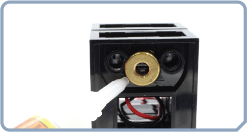
FIGURE 2-13: Apply a few drops of Super Glue to keep the laser from moving.
Once the Super Glue dries, you can tend to the electrical connections. In order to protect the bare wires, keep them from shorting out, and follow a good safety practice of not leaving live electrical circuits exposed, cover all the electronics with Sugru moldable glue in a technique known as encapsulation. Sugru feels like modeling clay when fresh from the package, but it hardens into a rubbery form. With the circuit turned off, wrap Sugru around the electronics, as shown in Figure 2-14.

FIGURE 2-14: Cover all the electronic components and bare wires with Sugru.
When fully encapsulated, the Sugru blob should have a lima bean shape, as in Figure 2-14, and you should be able to tuck it away inside the hollow lower section of the gearbox. Pack the remaining Sugru around the hole of the gearbox where the LEGO wire cable enters, as shown in Figure 2-4. This relieves strain on the wire cable by keeping the wires from rubbing around or twisting.
adding a cover to the laser structure
With the electronics encapsulated and tucked into the gearbox, you can now add a cover for the laser module housed within the gearboxes. This cover, shown in Figure 2-15, will hide and protect the Zener diode circuit and give strength to the LEGO-Compatible Laser as you attach it to various LEGO inventions.

FIGURE 2-15: Done! Your LEGO-Compatible Laser is complete and ready to use.
The cover also provides a place for the warning label sticker pointing at the laser output. Building instructions for the cover are shown here.


what you learned
In this chapter, you built a laser that is compatible with LEGO constructions. You learned how to work with diode laser modules, by building a LEGO housing for the laser and an electrical circuit to provide power from a LEGO battery box. You can now put the LEGO-Compatible Laser to use, starting in the next chapter with a laser-based security system.