3
the laser security fence
In this chapter, you’ll build an intrusion detection system that sounds an alarm if an intruder crosses a certain boundary. For it to be useful, you’ll need to build a device that can detect objects at a distance of several meters—the width of the approach to a doorway, at least. The MINDSTORMS EV3 Infrared Sensor, used in Chapter 1 for the Motion-Activated Critter Cam, can detect only objects that come pretty close to the sensor. To warn you of approaching people, you’ll build a Laser Security Fence that uses the LEGO-Compatible Laser from the previous chapter to project a line and then sounds an alarm if an intruder crosses that line.
building the laser security fence
The Laser Security Fence is composed of two parts: a laser that projects a laser beam and a sensor to detect changes in the beam’s intensity. For the laser, you’ll use the LEGO-Compatible Laser you built in Chapter 2. For the sensor, you’ll build a MINDSTORMS EV3 sensing device. Figure 3-1 shows both of these parts.

FIGURE 3-1: The Laser Security Fence uses a Color Sensor to detect interruptions of a laser beam.
The sensing device will use a Color Sensor, part of the MINDSTORMS EV3 #31313 set, attached to the side of the EV3 Intelligent Brick to detect the light beam from the laser. If intruders cross the fence, they’ll interrupt the beam, triggering an alarm and flashing lights.
what you’ll need
You’ll use the LEGO parts in Figure 3-2 to create a structure to hold and tilt the laser. This figure also includes the LEGO components to hold the Color Sensor. An asterisk indicates a LEGO part not found in the MINDSTORMS EV3 #31313 set.
You’ll also need the LEGO-Compatible Laser built in Chapter 2, including its battery box.
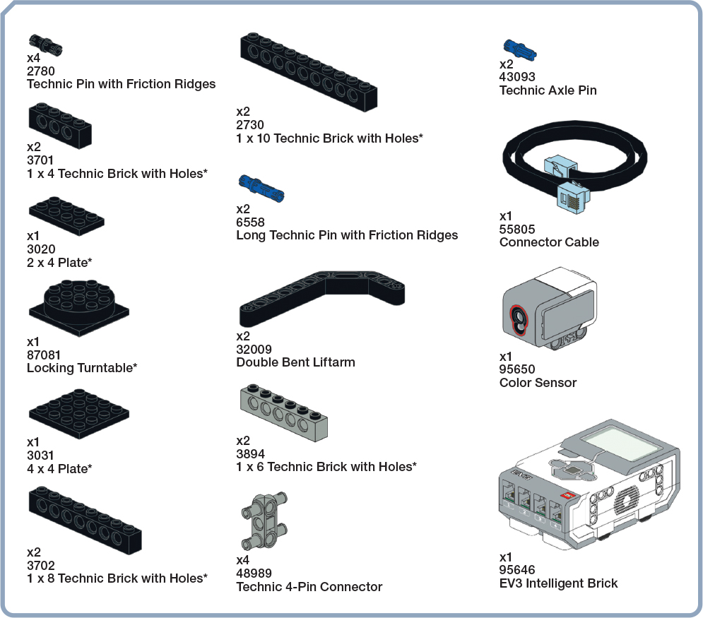
FIGURE 3-2: Parts used to build the Laser Security Fence
building the LEGO-compatible laser mount
The LEGO-Compatible Laser mount, shown on the left side of Figure 3-1, takes advantage of the weight of the battery box to create a solid base for the laser. Follow these steps to build it.


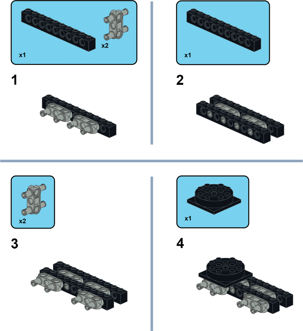
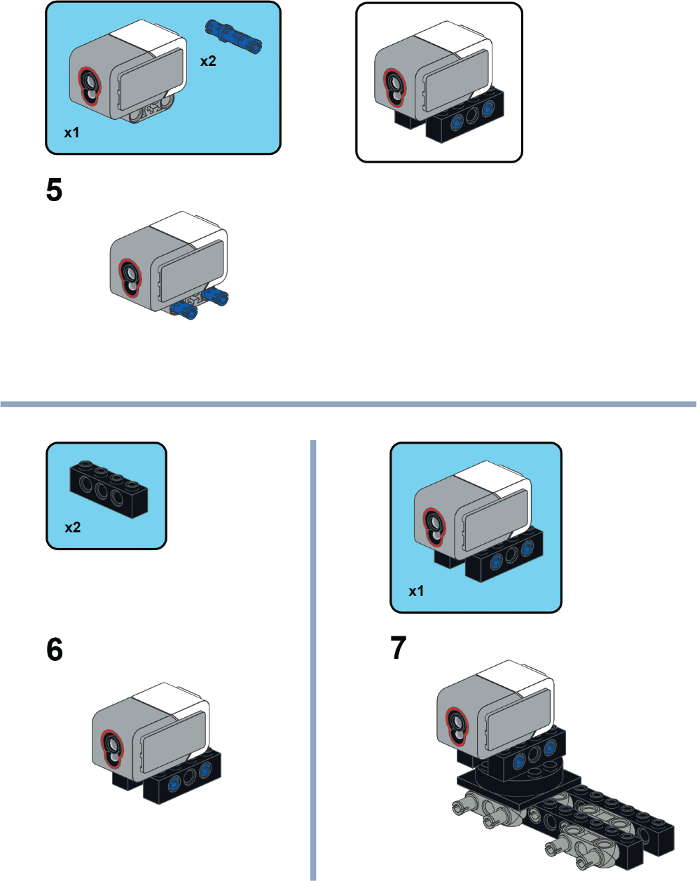
building the sensor mount
Use the following steps to build a mount for the EV3 Color Sensor. You’ll attach this mount, in turn, to the side of the EV3 Intelligent Brick, as shown in Figure 3-1. The Color Sensor’s mount features a locking turntable that helps align the sensor to the laser beam.

writing the software
You’ll control the Laser Security Fence by programming the EV3 Intelligent Brick. This program, shown in Figure 3-3, will monitor the light-level reading from the Color Sensor to determine whether the laser beam drops in intensity, which should occur if something crosses the beam.
The Color Sensor has many modes of operation for measuring or comparing color, reflected light intensity, and ambient light intensity. In conjunction with a Switch block, you’ll use a mode of operation called Color Sensor–Compare–Ambient Light Intensity, which measures the brightness of the light on the face of the Color Sensor.

FIGURE 3-3: The program for the Laser Security Fence is based on the Color Sensor–Compare–Ambient Light Intensity mode of a Switch block.
If you’re new to programming MINDSTORMS EV3, you can find instructions to get started in Chapter 1. This program uses the following blocks:
Loop block This makes the program repeat infinitely. This means the program will constantly test for whether the laser beam is striking the Color Sensor.

Drag a Loop block onto the screen and place it next to the Start block in the programming area.
Switch block This block creates true and false paths based on readings from the Color Sensor. You’ll set this block to Color Sensor–Compare–Ambient Light Intensity. In this setting, the Switch block tests whether the light intensity seen by the Color Sensor is above or below a threshold level. If the light intensity level seen by the Color Sensor is less than 25, the true path of blocks 3 through 9 is taken. If the level is 25 or higher, the false path of blocks 10 through 14 is taken.

Place the Switch block inside the Loop block. Set Switch–Color Sensor to Color Sensor–Compare–Ambient Light Intensity, Port to 4, Compare Type to 4, and Threshold Value to 25. You may need to adjust the threshold level depending on the background light level (whether you’re inside a dark room or outdoors in the sun) or the laser you’re using. In bright sunlight, you should set the threshold to about 70. For help determining how to set the threshold, check the ambient light reading on the Display block in step 9. The threshold should always be higher than that value.
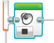
Sound block Place this block in the true path created by the Switch block. If the Switch block reports the true condition because the laser beam is interrupted, this block begins playing a sound on the EV3 Intelligent Brick’s speaker. You can select various beeps or musical tones from the Sound block’s drop-down menus.

Place a Sound block in the true path of the Switch block. Set Sound to Play Tone, Frequency to 2093, Duration to 1, Volume to 30, and Play Type to 1.
Brick Status Light block After the Sound block plays, this block flashes a yellow light on the front of the EV3 Intelligent Brick to indicate an alarm condition. If you prefer, you can make this light red or green.

Place the Brick Status Light block after the Sound block. Set Brick Status Light to On, Color to 1, and Pulse to True.
Wait block This block keeps the yellow alarm light on for 3 seconds, giving you time to notice that an alarm event has occurred.

Connect a Wait block after the Brick Status Light block. Set Wait to Time and Seconds to 3.
Brick Status Light block This block turns off the yellow alarm light at the end of the alarm warning event.

Connect the Brick Status Light block after the Wait block. Set Brick Status Light to Off.
Display block To help set the threshold value in the Switch block, the Display block creates a display on the EV3 Intelligent Brick’s front panel that shows the current ambient light level. You’ll add text to this block to display the message ambient intensity. This will serve as a label for the light level detected by the sensor in the next step.

Connect the Display block after the Brick Status Light block. Set Display to Text–Pixels, Text to ambient intensity =, Clear Screen to True, x to 0, y to 25, Color to False, and Font to 0. The x- and y-coordinates in these menus determine the position where the text will appear on the front panel display of the EV3 Intelligent Brick.
Color Sensor block This measures the intensity of the light detected by the sensor when the laser light has been blocked. This measurement becomes useful when you decide which threshold value to set in block 2. The threshold should be a little above the background light level measured in this step. You’ll display the measurement in the following step.

Attach the Color Sensor block after the Display block. Set Color Sensor to Measure–Ambient Intensity and Port to 4.
Display block This block shows the ambient light intensity measured by the Color Sensor. It uses a wire connection to take the measured light intensity from block 8 as a text input into the Display block. The measured value should appear on the EV3 Intelligent Brick’s front panel, to the right of the text label created in block 7.
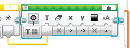
Place the Display block after the Color Sensor block. Set Display to Text–Pixel, Text Type to Wired, Clear Screen to False, x to 5, y to 75, Color to False, and Font Size to 2. Connect a wire between the output of the Color Sensor block and the input of the Display block. To make the wire connection, hover your mouse over the output of the Color Sensor. An icon of a spool of wire should appear. Click and hold the Color Sensor output and drag your cursor to the input of the Display block. The wire connection should then appear as a yellow line.
Sound block In the false path, which occurs as long as the laser beam is hitting the Color Sensor, turn off all alarm sounds by inserting this Sound block. This block ensures that the sound from the alarm doesn’t continue after a previous alarm occurrence.
Place the Sound block into the false path of the Switch block and set Sound to Stop.
Brick Status Light block This block turns off the indicator light on the EV3 Intelligent Brick front panel, because there is no alarm condition in the false path.

Place a Brick Status Light block after the Sound block and set Brick Status Light to Off.
Display block Similar to what you programmed in the true path, this block creates a text label that displays the message laser intensity to identify the reading from the Color Sensor.
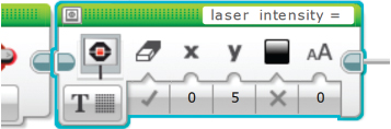
Place the Display block after the Brick Status Light block. Set Display to Text–Pixels, Text to laser intensity =, Clear Screen to True, x to 0, y to 5, Color to False, and Font to 0.
Color Sensor block This measures the intensity of the laser light seen by the sensor when the laser is illuminating the Color Sensor. The value measured here can help you align the sensor to the laser beam, as you’ll see in the next section.

Attach the Color Sensor block after the Display block. Set Color Sensor to Measure–Ambient Intensity and Port to 4. The output from the Color Sensor will be fed to the next block in the program sequence.
Display block This block shows the laser light intensity measured by the Color Sensor block, using the measurements from the Color Sensor as input to display on the EV3 Intelligent Brick.
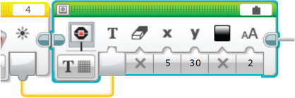
Place the Display block after the Color Sensor block. Set Display to Text–Pixels, Text Type to Wired, Clear Screen to False, x to 5, y to 30, Color to False, and Font Size to 2. Connect a wire between the output of the Color Sensor block and the input of the Display block.
After completing the program, download it into the memory of the EV3 Intelligent Brick. If you’re not familiar with the download process, review it in Chapter 1. Your Laser Security Fence is now ready for installation.
using the laser security fence
Place the LEGO-Compatible Laser and Color Sensor on structures of the same height so the laser beam aligns with the face of the Color Sensor. You may need to tilt the laser by a pivoting the joint built into the mount.
Figure 3-4 shows the Laser Security Fence set up across two exterior doors and a window at the back of a house.
In this example, the two ends of the Laser Security Fence sit on handrails, and the laser covers a distance of 12 meters. An attempted entry at either of the two doors or the window sets off the alarm. Notice that the mark of the laser beam on the face of the Color Sensor is larger than the beam when it left the laser. All laser beams expand over distance, a property called divergence.
With setups that cover 10 meters or more, you might struggle to align the laser beam onto the Color Sensor by tipping the laser mount. Try adjusting the angle of the laser and then moving the light sensor into the beam path. You can also place LEGO bricks under the EV3 Intelligent Brick to raise the height of the light sensor, as shown in Figure 3-4.

FIGURE 3-4: The Laser Security Fence guards the back of a house.
If you plan to install the Laser Security Fence outside for a long time, you could make LEGO brick housings to protect the laser source and EV3 Intelligent Brick. Alternatively, you could place one or both ends of the setup indoors with a view through a window, as shown in Figure 3-5.

FIGURE 3-5: You can place one or both ends of the Laser Security Fence indoors with a view through a window.
In this configuration, the sensor is indoors, and the laser is sitting on top of a fence post outside. Transmitting the laser beam through the window glass weakens the beam’s intensity, so it hits the Color Sensor at about 90 percent of its normal value. Most of the loss comes from the reflection of the laser beam off the glass. You may need to adjust the threshold level in the Switch block of the program to account for the lost laser intensity.
ideas for going further
Instead of triggering an alarm, the Laser Security Fence could activate another protective action. You could change the code so it activates a camera to record video or pictures, as you did in Chapter 1. You could also turn on security lighting by using the IoT Control Relay device described in Chapter 6. Instead of using the laser beam in a straight line, the Laser Security Fence could protect the area around a corner by using a mirror. You’ll learn about using a mirror with a laser beam in Chapter 11.
The laser used in this chapter has a visible red color, so it’s possible for an intruder to see the beam. If you want to avoid detection, you could use an invisible infrared laser. The Color Sensor end of the Laser Security Fence will still work with an infrared laser as long as its wavelength is below 1,100 nanometers. Aligning an infrared beam requires special tools and techniques, and Chapter 5 explains how to work with them.
what you learned
In this chapter, you used a laser to build the Laser Security Fence, which can detect intrusion or motion over a long distance—much longer than a MINDSTORMS EV3 Infrared or Ultrasonic Sensors can. You also learned to use a MINDSTORMS Color Sensor to detect various light levels.