
Part II: WIRELINE TECHNOLOGIES
7
PAVING THE ROAD TO Gbit/s BROADBAND ACCESS WITH COPPER
7.1 INTRODUCTION
Ubiquitous low-cost broadband access is a key enabler of quality of life and modern economy. The demand on end-user data rates keeps increasing, which in turn fuels the development and deployment of new systems. Fixed broadband access technology is evolving from exclusively copper-based solutions to hybrid fiber/copper architectures. A recent analysis of this evolutionary process has revealed that there is a gap—a missing, not foreseen system generation [1]. This chapter is devoted to this expected next step in the evolution of broadband systems, here named the 4th-Generation Broadband concept. It identifies a technical, infrastructural, and economical niche and describes how the fiber access network is extended and forked to feed a last and ultimate generation of DSL systems, shown to have gigabit potential.
Our classification of broadband systems into “generations” contains only broadband systems operating on the twisted copper pairs of the public telephony network and optical fiber—that is, DSL systems and fiber access systems. The future, as well as the present, will certainly see also other technologies such as coaxial cable access systems (using cable TV infrastructure) or fixed wireless access systems, but we leave these outside the scope of this presentation.
In Figure 7.1 the principal deployment history for broadband access equipment is sketched. Note that the classification of systems as generations in Figure 7.1 is introduced to define and emphasize a gap in the foreseen broadband evolution and is not a generally accepted terminology. The term broadband access equipment loosely denotes communications equipment intended, for example, for Internet access with a permanent connection—that is, post-dial-up systems. During the last two decades, two generations of broadband access systems for telephone loops have been rolled out: Generation 1, which is mainly based on ISDN (cf., e.g., Stallings [2]) and Generation 2, which is mainly based on ADSL (cf., e.g., Golden et al. [3]). Both generations are characterized by systems deployed from the Central Office. Generation 1 marked the start of data communication beyond dial-up modems, while Generation 2 added a “real” transport network and user bandwidths comfortably greater than voiceband modems.
Figure 7.1. A sketch of deployment volumes of broadband access techniques (number of new installations or upgrades per time unit). The x axis is based on historical data (up to the present time), while the y axis is no more than an illustration of trends.
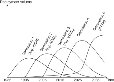
Today we are seeing the launch of the Generation 3 broadband access system, the VDSL family [3], which will provide customer data rates of up to 100 Mbit/s. While ADSL operates from the central office, often over cables that are several kilometers long, VDSL is designed to operate over shorter loops. Therefore, the VDSL equipment is normally placed in cabinets, resulting in a typical loop length that is below 1 km. The backhaul solution—that is, the technology to bring data between the transport network and the cabinet—is today almost exclusively based on optical fiber technology. The transition from Generation 2 to Generation 3 thus implies an extension of the fiber network from the Central Offices to the cabinets. This is a first and fundamental step toward spawning a large-scale fiber-to-the-home (FTTH) infrastructure.
Generation 4, presented and discussed here, is nothing more than the logical extension of the thinking behind Generation 3. The communication needs of the future are assumed to require data rates an order of magnitude higher than those of Generation 3—that is, a step from around 100 Mbit/s to around 1 Gbit/s. To deliver these data rates using the in-place copper architecture then requires even shorter loops. The key question is whether or not there exists a natural place to deploy the new transmission equipment in an economical fashion.
With the 4th-Generation Broadband concept, we would like to bring out the “Last Distribution Point,” hereinafter referred to as Last DP, as a candidate from which broadband services could be delivered in a technically and economically feasible fashion. The copper plant is a star network, forking out into finer and finer segments (fewer and fewer lines running together) until eventually individual twisted pairs reach their respective user premises. The Last DP can be found by following the lines from the users’ homes and backwards into the network, where normally after 20–200 m you find a point in which a number of lines merge together and form a bundle. This is the most outward point at which a modem pack can be installed serving several (say 10–30) customers. The Last DP was touched upon as early as 1990, in the form of fiber-to-the-building (FTTB) and fiber-to-the-curb (FTTC) discussions but at the time not associated with a corresponding new generation of copper access (DSL) equipment making full use of the greater bandwidth offered by the shorter loops. The earlier FTTB and FTTC discussion left little mark in the standardization processes and were essentially abandoned.1 We believe that it may be time to awaken the idea of moving to the Last DP, but now dressed in modern technology and based on 20 years of experience from the development of the broadband market.
A natural question is, of course, how much this infrastructural quantum leap will cost, especially in comparison with installing optical fibers all the way out to the customer (FTTH). We return to this in the next chapter.
Figure 7.1 contains historical data for Generations 1 to 3, along with predictions of the deployment timescale for the 4th- and the 5th-Generation broadbands.2 So far, the transition between any consecutive pair of earlier generations has taken about 10 years. This suggests that the process that leads to the creation of a new-generation broadband has a period of 10 years, based on the lead time in standardization and product realization.
The supported data rate increases by roughly an order of magnitude from generation to generation. This also applies to the step from voiceband modems, which can be viewed as Generation 0, to Generation 1. The step to 4th-Generation broadband (4GBB), using the Last DP and, possibly, vectoring technology [4], will provide data rates on the order of 1 Gbit/s—that is, 10 times the data rate of Generation 3 (e.g., VDSL2 with up to 100 Mbit/s).
Applying the above argument to 20 years from now, the bandwidth demand should then have increased another order of magnitude to 10 Gbit/s per household, serving as an outlook toward the technical specifications of Generation 5 (FTTH). According to the prediction in Figure 7.1, the 5th Generation’s deployment volume will gradually increase, exhibiting a peak around 2035.
7.2 HYBRID FIBER/COPPER-BASED BROADBAND ACCESS NETWORK
In most operational telecom networks, the topology of the access loop looks like the example network situation depicted in Figure 7.2, where one primary cable connects the Central Office (CO) to various street cabinets (in the figure labeled “DP in Cab” meaning distribution point in cabinet), and from there we have stepwise forking out to reach the users’ premises.
Figure 7.2. Access network topology and deployment scenario. This particular cable serves the outskirts of a small city in Sweden.
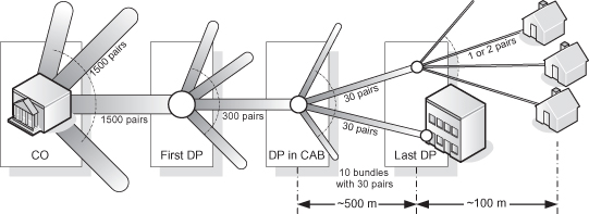
This structure is typical to all major telecom networks, although the distances and the number of lines per cable vary both between countries and between central offices. A typical CO has on the order of 15 primary cables, each with about 1500 pairs. Each cable, in turn, serves around half a dozen street cabinets, making normally between 50 and 100 cabinets per central office, serving some 20,000 households and other customer locations.
The average length of a copper pair connecting the customer with the CO is ranging from 1.5 km to 3 km, depending on country and area. This distance is the main obstacle to increasing the bandwidth from Generation 2 systems, where best-in-class is ADSL2+ in practice normally providing between 10 and 20 Mbit/s, to the higher bit-rates offered by Generation 3, today VDSL2 with up to 100-Mbit/s per copper pair. By instead placing the transmission equipment in cabinets, it is possible to reduce the average length to less than 1 km (cf. Figure 7.2). The cabinets will then typically be connected to the CO using optical fiber, as well as to the users with VDSL2. However, and mainly in urban areas, the deployment of cabinets is unfeasible due to the difficulties in their installation and in the obtention of the required permissions.
The Generation 4 broadband is the next logical step to shorten the loops, increase the bandwidth, and extend the optical fiber access network. The transmission equipment would then be placed in the Last DP (cf. Figure 7.2) and typically connected to the CO with newly deployed fiber. The user will still be linked to the Last DP by means of a copper pair.
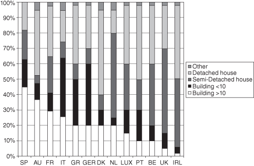
The alternative to the Generation 4 concept described here is to deliver the fiber all the way out to every customer—that is, FTTH or Generation 5 systems in our terminology. The problem with all deep-fiber strategies (see Figure 7.3), and the reason why the technique is detained, is the cost of deploying the fiber (i.e., civil works), as well as the cost for the fiber itself. The question is then how far it should be extended. Considering that the most costly part of the connection is from the Last DP to the customer, since it means digging and ducting for each residence, it is of prime importance to take into account the dominant type of dwelling house per country (Figure 7.4). The Last DP is installed where a balance is found between the amount of homes passed and their distance to the DP. Therefore, in Spain, where almost 60% of its population lives in apartment buildings or towers, the Last DP is usually located in basements (FTTB). On the opposite side, Ireland, where most people live in detached/semi-detached houses, the Last DP is mostly present within street cabinets (FTTN). In the vast majority of cases, the distance between the Last DP and the customers’ homes should be less than 100 m. In Copper and Faulkner [5], the drop wire distribution for an access network is shown; here only a small fraction of the lines are longer than 60 m.
Figure 7.3. CAPEX for the different FTTx flavors.
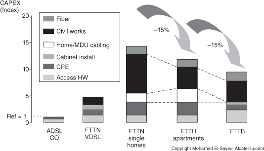
Figure 7.4. Dwelling-house type per country in Europe.
According to the techno-economic investment evaluations in, for example Olsen et al. [6], the deployment of FTTH can mostly be justified in particularly dense urban areas, while the cost of deploying fiber to the Last DP is moderate. As a rough estimation, using the example of Figure 7.2, replacing the copper from the cabinet to the Last DP will imply digging 5 km (500 m × 10 bundles), while replacing the cabling from the Last DP to each house will mean an additional 30 km per cabinet (100 m × 30 × 10). Considering an average cost for digging and ducting of 105 kEuro per km, then the cost is 0.515 MEuro for the fiber needed for the 4th-Generation broadband, while an extra 3.15 MEuro has to be thrown in to go to FTTH. This cost difference is the key realization bringing the insight that there is a niche for a 4th-Generation broadband system.
7.2.1 Thoughts on Backhaul Solutions
The connection between the 4th-Generation broadband (4GBB) equipment and the Central Office can be realized in more ways than using optical fiber. Although this is not central to the 4GBB concept, it is a field of possible innovation.
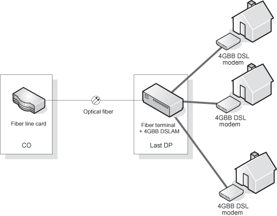
If the 4GBB concept was to be deployed today, it is likely that a passive optical fiber network (PON) architecture (see Figure 7.5), would offer the most priceworthy solution. This solution could be reasonably “future proof” in that, without additional investments in fiber, the optical transmission equipment could be upgraded—for example, from G-PON (gigabit-capable PON) to 10G-GPON or WDM-PON—when such new technologies become available.
Figure 7.5. Topology with fiber to the Last DP.
Staying with technology available today, a principal alternative to a new, extended, fiber infrastructure would be to utilize the copper that is already in the ground. A group of copper pairs, preferably a whole cable binder (bundle), could be allocated to a DSL technology, creating a large shared bit-pipe (see Figure 7.6). This shared bit-pipe would use bonding [7, 8] to provide trunking gain thanks to statistical multiplexing of user traffic, and vectoring (defined by the ITU standards project “G.vector”) to cancel crosstalk between the pairs, increasing the attainable bit rate (techniques discussed in more detail in Section 7.3). In reference 9, 0.5 Gbit/s was achieved with a prototype bonding and vectoring system, over a distance of 0.5 km using six pairs. Extrapolating this result to a binder with 30 pairs then gives 2.5 Gbit/s, which is on par with the performance of a GPON link (2.448 Gbit/s). It is expected that further refinements of the technology could achieve such performance over longer distances than 0.5 km, perhaps up to 1 km depending on cable gauge.
Figure 7.6. Topology where a shared copper binder is used between cabinet and Last DP.
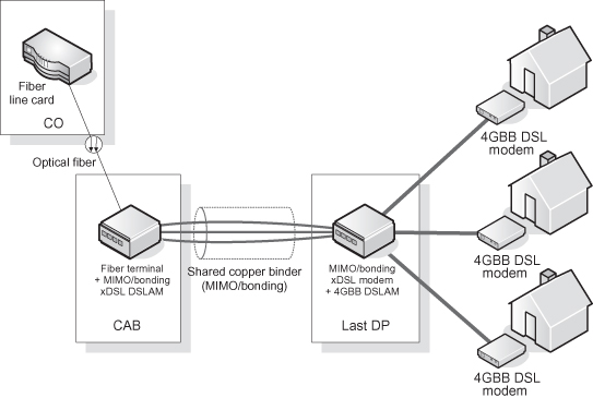
A backhaul reach of 0.5–1 km is of course much shorter than the reach of a GPON link (typically 20 km). However, it could become an option to use the copper binder as a backhauling solution between the cabinet and the Last DP where the distance is typically less than 1 km (and where there often is no ducting; see Figure 7.6), thereby avoiding or postponing the cost of digging.
Further capacity enhancements can be achieved if the copper binder is not restricted to use only differential signaling (see Section 7.3.2). Using Multiple-Input Multiple-Output (MIMO) schemes [10] applied to cancel crosstalk and spatially correlated noise, the 30-pair binder could be converted to a 60 × 60 or 59 × 59 MIMO channel depending on whether or not the binder shield can be used as a conductor. The copper backhaul solution discussed above could, as discussed, be suitable for shorter ranges, supporting several Gbit/s from the cabinet to the Last DP [11]. This scheme would then be similar to the CuPON concept proposed by Cioffi et al. [12] in the sense that the copper is shared but different in the sense that the shared DSL system is only used for the backhaul (e.g., from the cabinet to the Last DP).
It is also important to understand how the DSLAMs at the Last DP will, as any other active equipment, be powered. There are essentially three alternatives to power equipment in the Last DP:
- Local power from utility poles, lamp posts, or similar sources. This could be very expensive for the small number of lines considered here since there is often a metering fee incurred. However, if the Last DP is located in a building basement, it could be possible to get power from the building owner without a metering fee.
- Forward powering, using the available twisted-pair copper to feed power from the CO or cabinet to the Last DP. Commercial solutions for forward powering exist today but are often too powerful, bulky, and expensive for the small number of lines considered here. If suitable equipment for forward powering to the Last DP becomes available, it would be natural to feed power over the same copper lines as used for the backhaul discussed above.
- Reverse powering, where power is fed from the subscriber equipment to the DSLAMs [5]. Since the copper lines between the Last DP and customers’ homes are very short, the resistive losses will typically be much lower than for forward powering. This is perhaps the most promising solution, but there are some issues that need to be solved before this can become successful—for example, a model for how to compensate the subscribers for paying the DSLAM power consumption.
The three powering solutions above are likely the most realistic ones. The results of Copper and Faulkner [5] show that reverse powering is the cheapest when there are few subscribers per node while local powering becomes cheaper for large number of subscribers. In certain environments it may also be possible to utilize battery-backed solar power or wind power, but it remains to be seen whether such a powering solution will be feasible.
7.3 PHYSICAL-LAYER TECHNIQUES FOR THE LAST DROP
This section discusses the technical ingredients that are available to enable data rates on the order of Gbit/s over the copper cable connecting the Last DP with the customer’s premises. The data rate that can be achieved with an arbitrarily low bit error rate is limited by the channel capacity:
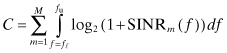
in bit/s, where M is the number of
independent “channels” (or modes), B
= fu − f![]() is the available
bandwidth in hertz, and SINRm( f ) is the frequency-dependent
signal-to-interference-plus-noise-power ratio of the receive channel mode m. Consequently, there are the following ways to increase
the throughput:
is the available
bandwidth in hertz, and SINRm( f ) is the frequency-dependent
signal-to-interference-plus-noise-power ratio of the receive channel mode m. Consequently, there are the following ways to increase
the throughput:
- Increase bandwidth B.
- Increase the number of independent modes M.
- Increase the signal-to-interference-plus-noise-power ratio
SINRm(f)
of the receive signal for all (or some) frequencies f ∈ [f
 , fu].
In general, the potential gain in throughput when increasing the number of channels M or the available bandwidth B is larger compared to increasing the signal-to-noise-plus-interference-power ratio SINRm(f) since C grows linearly with M and B but only logarithmically with SINRm(f). While increasing the bandwidth is technically straightforward, there are many options for both increasing the number of modes and increasing the signal-to-noise-plus-interference-power ratio. In the following, a survey of these (mostly) physical-layer techniques is presented.
7.3.1 Bonding
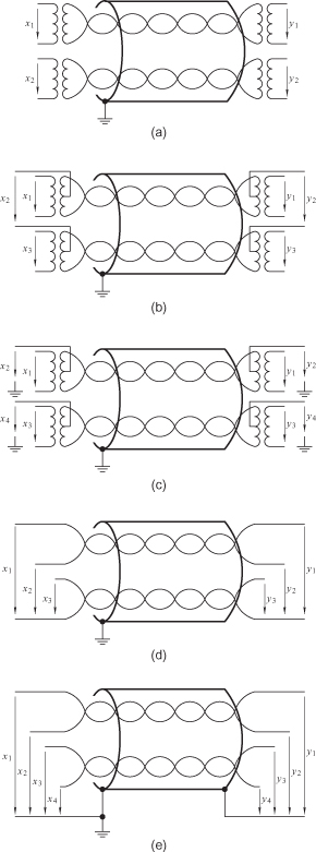
In many countries, there are cables with two (or even more) twisted pairs connecting the Last DP with a customer’s home. Only two of these wires (one pair) are actually used for telephony and DSL. Without much effort, a second pair (or even more, if available) can be exploited (cf. Figure 7.7a). In essence, this does not require any physical-layer processing, but only a simple interleaving of the data streams to be received or sent over the two (or more) lines—a technique that is already in place in various forms and referred to as bonding [7, 8]. As simple as it is, adding channels via bonding does not exploit the potential of a cable to its full: While the number of independent channels M increases, the signal-to-noise-plus-interference-power ratio SINRm(f) of all channels m ∈ {1, … M} decays due to increased crosstalk among the bonded lines.
Figure 7.7. Various ways to increase the number of channels (modes): (a) Bonding. (b) Common-mode signaling. (c) Common-mode signaling exploiting the shield or earth. (d) Split-pair signaling. (e) Split-pair signaling exploiting the shield.
7.3.2 Alternative-Mode Signaling
Traditionally, signaling over copper cables is realized via loops formed by twisted-wire pairs. The information is represented as the voltage applied (at the transmitting end) or measured (at the receiving end) between the two wires—a way of signaling that is referred to as differential-mode signaling. The main advantage of differential-mode signaling is its high immunity with respect to surrounding electromagnetic fields.
A way to increase the number of channels M is to exploit alternative ways of signaling which result in alternative modes. Recent research suggests that we entirely abandon the twisted-pair concept and adopt a multi conductor view: Instead of using the K differential modes of a K-pair cable, 2K − 1 independent transmission modes can be exploited using alternative modes. In case the shield or earth is exploited serving as a conductor available at both ends of the cable, the number of exploitable modes is 2K.
From a technical perspective, there are various possibilities to obtain these modes. Figure 7.7 depicts a few examples. For the sake of simplicity, the number of wire pairs (loops) is chosen to be only K = 2. Common-mode signaling excites both wires of a loop with respect to a common reference, which can be the common potential of another loop yielding the configuration depicted in Figure 7.7b with three (in general 2K − 1) independent modes [13–15]. In case earth or the shield is used as common reference [15], the common mode of each loop in the cable can be exploited, yielding four (in general 2K) independent modes as depicted in Figure 7.7c. Another setup, referred to as split-pair signaling [11], uses one wire as reference yielding three (in general 2K − 1) independent modes for a two-pair cable (cf. Figure 7.7d). Extending this idea to a cable with a shield, yields four (in general 2K) modes (cf. Figure 7.7e). In general, alternative modes may be more susceptible to surrounding electromagnetic fields and thus yield lower signal-to-noise-plus-interference-power ratio values SINRm(f) compared to differential-modes signaling. In order to exploit the potential of alternative modes, the SINRm(f)-values need to be brought to the same order of magnitude as available on differential modes.
7.3.3 Dynamic Spectrum Management
Dynamic spectrum management (DSM) comprises a multitude of techniques to improve the signal-to-noise-plus-interference-power ratio and is widely embraced within the DSL industry [16]. There are several levels of management:
- DSM Level 1 defines the management of average power values on a single-line basis. DSL lines practicing DSM Level 1 behave more “politely” to other lines by, for example, reducing the average power to the level that is needed instead of transmitting with the level that is actually permitted.
- DSM Level 2 defines joint management and optimization of average power of several DSL lines, which allows DSL lines to be even “more polite” and avoid the generation of crosstalk in certain frequency bands. The philosophy is simple but effective: If all lines in a cable follow a “politeness policy,” there is a benefit for every line in the cable.
- DSM Level 3 comprises the manipulation of the signals itself (instead of just their power), which allows for signal processing that eliminates (or at least mitigates) crosstalk either at the receiver (referred to as interference cancellation) or at the transmitter (referred to as precoding).
DSM Level 3 is sometimes also referred to as “vectoring” or “vectored transmission”—a terminology motivated by the fact that it is convenient to arrange signals of co-located transceivers in vectors for joint processing using linear algebra [4]. In combination with multicarrier modulation, vectoring allows us to eliminate the impairment caused by crosstalk at the cost of some signal processing.
A little example should help to illustrate the idea. Consider a two-pair system (four wires) used with differential signaling. For one subcarrier, the resulting spatial channel can be described by a 2 × 2 matrix H; for example,
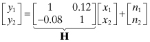
The direct paths have unit gain. The signal x2 transmitted on line No. 2 multiplied by 0.12 is the far-end crosstalk (FEXT) seen on line No. 1. The signal x1 transmitted on line No.1 multiplied by −0.08 is the FEXT seen on line No. 2. These values correspond to crosstalk-coupling functions’ magnitudes of around −18.42 dB (10 log10(0.122)) and −21.94 dB (10 log10(0.082)), respectively. With a signal-to-noise-power ratio of 30 dB, the resulting signal-to-interference-plus-noise-power ratios on the two lines are about 18.12 dB (10 log10(1/(0.122 + 0.001))) and 21.31 dB (10 log10(1/(0.082 + 0.001))), respectively. These are the values that can be achieved with bonding.
An example of vectoring with co-located receivers (interference cancellation) is based on the QR-decomposition of the channel matrix H yielding
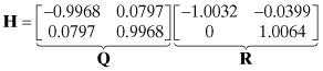
where R is upper-triangular and Q is a unitary matrix. Post-processing the receive signals with QH yields the resulting channel QHH = R, which has an upper-triangular structure. Consequently, x2 can be detected first. Assuming correct detection, the FEXT generated from line No. 2 can be reconstructed and subtracted before detecting x1. Since Q is a unitary matrix, post-processing does not change the noise power. The resulting detection signal-to-interference-plus-noise-power ratios are about 30.03 dB (10 log10(1.00322/0.001)) and 30.06 dB (10 log10(1.00642/0.001)), respectively. Note that these values in fact exceed the signal-to-noise-power ratio of 30 dB. In this sense, vectoring has turned the impairment caused by FEXT into an advantage.
The same decomposition can be utilized for vectoring with co-located transmitters. Direct application of this precoding idea, however, results in a transmit-power increase. Nonlinear precoding can be used to amend this problem [17, 18].
7.3.4 Multiple-Input Multiple-Output Techniques
In contrast to vectoring, which requires co-location of wire pairs on only one of the two sides, dedicated Multiple-Input Multiple-Output (MIMO) techniques require co-location of wire pairs on both sides. Continuing the example from the previous section, a simple MIMO-processing technique [19] could, for example, evaluate the singular value decomposition of the channel yielding
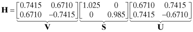
Pre-processing the transmit signals with UH and post-processing the receive signals with VH yields the resulting channel VHHUH = S, whose off-diagonal elements are zero. Since V and U are unitary matrices, pre- and post-processing does not change signal power nor noise power. The processing yields signal-to-interference-plus-noise-power ratios on line No. 1 and line No. 2 of around 30.21 dB(10 log10(1.0252/0.001)) and 29.87 dB (10 log10(0.9852/0.001)), respectively.
Although the gains depend on the actual coupling values, simple processing of this kind can yield notable improvements in signal-to-interference-plus-noise power ratio. Nevertheless, crosstalk caused by neighboring lines that are not part of the MIMO system (or of the vectoring system) remains and can be tackled using the ideas discussed next.
7.3.5 Extrinsic Interference Cancellation
Besides crosstalk, which originates inside the cable or the wire system consisting of a number of lines, there may be interference originating from radio sources. Examples include AM radio stations, TV stations, and electrical household appliances. In fact, the major part of the 30 to 200-MHz frequency band is occupied by broadcast TV and radio stations. Furthermore, crosstalk originating from lines that do (for whatever reason) not participate in DSM practices constitutes extrinsic interference. In contrast to crosstalk originating from a line belonging to the system (and thus practicing DSM), there is no reference (a strongly correlated signal) available for interference cancellation. However, a reference can be obtained by exploiting an unused line to “listen.” In essence, this line functions like a receive antenna providing a signal that is strongly correlated with the interference and can thus be used for interference cancellation.
It is reasonable to assume that the susceptibility with respect to extrinsic interference of alternative modes is higher compared to differential modes. It may thus be beneficial to employ interference cancellation together with alternative-mode signaling. As pointed out in Lee et al. [11], the ratio of achievable data rates with alternative-mode signaling and with standard differential-mode signaling can be roughly estimated as follows. Without extrinsic interference, the gain is proportional to the number of modes: (2K − 1) / K. In the presence of extrinsic interference, one alternative mode can be used to acquire a reference signal of the interference for subsequent cancellation. The resulting ratio of data rates is thus roughly (2K − 2) / K. Consequently, for a two-pair drop cable without shield operated in the presence of extrinsic interference, alternative-mode signaling may yield no note worthy improvement. Clearly, the ingress/egress issue is critical since alternative-mode loops are not twisted. However, cable shields could mitigate the problem.
7.4 REGULATORY AND LEGAL ASPECTS
Copper cables used for data transmission act like antennas and thus both pick up unwanted interference (a process referred to as ingress) and emit electromagnetic waves (a process referred to as egress). While the former impairs the performance of high-speed data transmission over the cable, the latter may create conflicts with other services.
Ingress and egress mechanisms, described in Foster and Cook [20], can be roughly sketched as follows. Transmission of data over a wire pair is carried out by differential excitation of the pair (i.e., excitation of the circuit formed by the two wires of a pair). Due to imperfection of geometrical and consequently also of electrical symmetry of each wire pair with respect to earth, the differential signal causes a corresponding common-mode excitation of the wire pair (i.e., excitation of the circuit formed by the wire pair constituting a single conductor and earth). The pair of wires then behaves like a transmit antenna and causes unwanted egress. The degree of symmetry (or asymmetry) causing the differential-mode to common-mode conversion, an important property of a wire pair or a cable, is referred to as balance and is quantified by the ratio of the corresponding voltages or currents. While the balance can reach values around 70 dB in the voiceband (i.e., in the kilohertz-range), it decreases significantly with increasing frequency [10]. Extrapolating measurement results collected for frequencies up to 30 MHz, the conservative assumption that the balance decays linearly from 35 dB in the voiceband to 25 dB at 100 MHz is adopted hereinafter.
Conversely to egress, a time-varying electromagnetic field in the vicinity of a wire pair causes a common-mode excitation of both wires with respect to earth. The wire pair simply behaves like a receive antenna. The balance, which is a reciprocal property, determines the amount of resulting differential-mode ingress caused by common-mode to differential-mode conversion.
As a principal assumption, Foster and Cook [20] suggests that an electromagnetic field with electric field strength x V/m causes an induced worst-case common-mode voltage of x V, an observation that is mainly based on experience gained through measurements both in the laboratory and in the field. Independent theoretical and experimental work [21, 22] supports this observation to an extent large enough to warrant application for throughput predictions.
7.4.1 Egress
For the frequency range 0–30 MHz, the invoked egress limits orientate themselves on the standardized VDSL band plans, adopting the transmit power spectral density (PSD) limit of −60 dBm/Hz. The standard3 [23], hereinafter referred to as CISPR-22, suggests a quasi-peak limit for radiation caused by an electric appliance measured at a distance of 10 m. The limit, which is specified in terms of electric field strength, is 30 dBμV/m measured in any band of 9 kHz width in the frequency range 30–230 MHz. A transmit PSD below −63 dBm/Hz ensures that this limit is on average not violated assuming a balance of 30 dB.
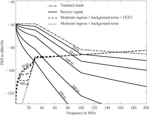
It is pointed out in Foster and Cook [20] that radiated emission with a field strength as low as 0 dBμV/m might be detected by, and thus cause disturbance for, radio receivers. Consequently, it is reasonable to assume a transmit PSD that decays linearly with frequency from −60 dBm/Hz at 30 MHz to a value at 100 MHz that ensures a field strength below 12 dBμV/m, which is the level caused by today’s modems in the amateur radio bands. Standardized band plans limit the PSD within these bands to −80 dBm/Hz. The impact of these bands on the throughput analysis is insignificant and thus neglected. Figure 7.8 depicts the resulting transmit PSD mask (dashed–dotted line) and the corresponding receive PSDs (solid lines) for different loop lengths.
Figure 7.8. Transmit and receive power spectral densities (PSDs): The uppermost line (dashed–dotted) is the transmit PSD mask, followed by receive PSDs (solid lines) for loop lengths 20 m, 50 m, 100 m, 200 m, and 300 m (AWG24/0.5 mm). Transmission is impaired by moderate ingress (−110 dBm/Hz), FEXT from one equal-length crosstalker, and background noise (−130 dBm/Hz).
7.4.2 Ingress
Reversely to the egress mechanism, the wires will pick up radiation caused by devices operating in close vicinity. Assuming that these devices operate at the radiation limits suggested by the CISPR-22 standard, the resulting ingress PSD4 is roughly −133 dBm/Hz for a balance of 30 dB—a level comparable to background noise. Apart from the radiation-induced interference, there is disturbance caused by conducted common-mode interference. Assuming that the wire pair obeys the limits suggested by CISPR-22, the resulting ingress PSD5 is roughly −90 dBm/Hz for a balance of 30 dB. Instead of an ingress level of −133 dBm/Hz, which corresponds to an ingress-free environment and is a rather unrealistic scenario, −110 dBm/Hz is assumed to characterize the situation of “moderate ingress.” A level of −90 dBm/Hz, on the other hand, characterizes “strong ingress” and appears to be a rather pessimistic assumption: Although radio interference is an issue for currently deployed DSL systems that operate mainly at frequencies below 10 MHz, ingress levels observed in the field are way below the worst-case CISPR-22 level mentioned above. To summarize, the two levels should embrace ingress levels encountered in practice and serve as a basis for throughput predictions.
In a FEXT-free environment, a background-noise PSD of −130 dBm/Hz is a widely accepted, though conservative, value for frequencies up to 30 MHz. Aiming at assumptions that can be referred to as realistic till conservative, a linear transition (in log domain) from the background-noise level at lower frequencies (ca. 10 MHz) to the CISPR-22 ingress level at higher frequencies (ca. 30 MHz) is assumed. The resulting noise PSD for a FEXT-free environment is shown in Figure 7.8 (dotted line).
As discussed in the previous section, the cable segments at the “customer end” of the access network exhibit short lengths and a low number of pairs. Consequently, it is reasonable to assume that the number of expected crosstalkers is low. Apart from the FEXT-free case, a scenario with both ingress and one equal-length FEXT disturber is considered.
7.5 A THROUGHPUT PREDICTION
The previous section established the feasibility of the new 4GBB hybrid fiber–copper topology at an affordable investment-cost per customer. This section presents a projection of the achievable throughput connecting the Last DP and the customer.
It turns out that electromagnetic compatibility of interacting equipment and services sets major limitations for the achievable data rates. Data transmission over wires causes radiation and potentially disturbs nearby equipment. This undesired effect is referred to as egress and limits the applicable transmit PSDs. Reversely, cables—in particular aerial drop wires—pick up extrinsic disturbances (generated outside the cable) referred to as ingress. Lacking dedicated ingress and egress regulations, we derive realistic ingress levels and transmit PSD masks from ingress and egress limits defined in the existing international standard on radio interference CISPR-22 [23]. Together with wideband cable models [24], these transmit PSDs and ingress levels provide the basis for throughput predictions.
Once the constraints in the form of transmit PSD, ingress PSD, and background-noise level are found, the computation of the achievable data rate is straightforward (cf., e.g., Golden et al. [3]). A signal-to-noise ratio gap of 9.5 dB is assumed, which yields the throughput achieved with uncoded QAM transmission at a bit error rate of 10−7, from which state-of-the-art channel coding would reduce the bit error rate to low enough levels for all common services. The results presented in the following represent aggregate downstream and upstream data rates.
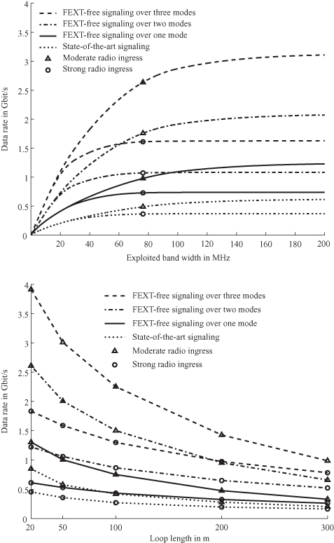
The following technology options for the link from the Last DP to the customer are compared:
- State-of-the-art (differential-mode) signaling over one twisted pair (existing solution).
- State-of-the-art signaling over one twisted pair in combination with vectoring, yielding one FEXT-free channel (or mode).
- State-of-the-art MIMO signaling over two twisted pairs in combination with vectoring (which eliminates crosstalk generated by lines outside the MIMO system), yielding two FEXT-free modes.
- Alternative-mode MIMO signaling over two twisted pairs in combination with vectoring (which eliminates crosstalk generated by lines outside the MIMO system), yielding three FEXT-free modes.
The achievable data rate versus exploited bandwidth is depicted in Figure 7.9 (top plot) for a 50-m drop wire. In general, the data rate increases rapidly with frequency for low frequencies and flattens out for high frequencies. Exploiting the bandwidth up to frequencies where the data rate flattens out will yield the throughput versus loop length depicted in Figure 7.9 (bottom plot). Exploiting the available bandwidth with state-of-the-art signaling is not sufficient to approach the Gbit/s limit. Very short loops in combination with vectoring, however, support data rates around 1 Gbit/s. MIMO techniques and signaling via alternative modes exceed the Gbit/s limit in the presence of strong ingress and boost the throughput to several gigabits per second in the presence of moderate ingress.
Figure 7.9. Top: Throughput over a 50-m drop wire versus exploited bandwidth for different technology options and both strong ingress (−90 dBm/Hz, marked by circles) and moderate ingress (−110 dBm/Hz, marked by triangles). Bottom: Throughput versus loop length.
7.6 CONCLUSIONS
In many countries, more than one-third of the population regularly uses the Internet. In addition to the tremendous residential usage, the market for small and medium-size enterprises is growing. The capacity within the backbone networks is virtually unlimited (at least in the sense that it is economically feasible to upgrade it to match virtually any need), leaving the transmission bottlenecks located within the first mile. The development of broadband services markets worldwide is thus dependent on having access networks that live up to the vision of the future society. In this area, a key enabler for the development of society, few new concepts have been presented. Notable exceptions are the work of Cioffi et al. [12], to which the 4th-Generation Broadband concept presented in this chapter is a natural complement.
Today, broadband strategies beyond VDSL2 are based on telecom operators eventually deploying fiber to the homes (FTTH) to meet future bandwidth demands. Although fiber offers the greatest potential as an access medium, deployment is hampered by prohibitively large investment costs. While remedies for this are sought, copper has still an important role to play, with the 4th-Generation broadband systems as a candidate for bridging the gap between today’s VDSL2 and FTTH. New fiber–copper-based systems that carry a partial investment in extending the fiber network manage a smooth migration from legacy networks to an all-fiber-optic network of the future.
Taking advantage of last distribution points close to the customer, exploiting the available bandwidth, and employing advanced signal processing techniques bring data rates on the order of gigabits per second to the customer.
Notes
1 It was recently pointed out by British Telecom researchers that technology developments will soon make it feasible to exploit the Last DP to deliver broadband services, spawning the work presented here.
2 Source: T. Magesacher, P. Ödling, S. Höst, E. Areizaga, P. O. Börjesson, and E. Jacob.
3 Comité international spécial des perturbations radioélectriques.
4 An electric field-strength of 47 dBμV/m causes a differential-mode voltage of 7.08 μV (balance 30 dB), which corresponds to a PSD of roughly
−133 dBm/Hz in 100 ![]() over a measurement bandwidth of 9 kHz.
over a measurement bandwidth of 9 kHz.
5 A conducted common-mode voltage of 90
dBμV causes a differential-mode voltage of 1 mV
(balance 30 dB), which corresponds to a PSD of roughly −90 dBm/Hz in 100 ![]() over a
measurement bandwidth of 9 kHz.
over a
measurement bandwidth of 9 kHz.
REFERENCES
1. P. Ödling, T. Magesacher, S. Höst, P. O. Börjesson, M. Berg, and E. Areizaga, The fourth generation broadband concept, IEEE Commun. Mag., Vol. 47, No. 1, pp. 62–69, January 2009.
2. W. Stallings, Integrated Services Digital Networks (ISDN), IEEE Computer Society Press, Washington, DC, 1985.
3. P. Golden, H. Dedieu, and K. Jacobsen (editors). Fundamentals of DSL Technology, Auerbach, Boca Raton, FL, 2005.
4. G. Ginis and J. M. Cioffi. Vectored transmission for digital subscriber line systems. IEEE J. Selected Areas Commun., Vol. 20, No. 5, pp. 1085–103, June 2002.
5. I. Copper and D. Faulkner, Reverse powering over DSL, in Proceedings of European Conference on Networks and Optical Communications, Krems, Austria, July 2007.
6. B. T. Olsen, D. Katsianis, D.Varoutas, K. Stordahl, J. Harno, N. K. Elnegaard, I. Welling, F. Loizillon, T. Monath, and P. Cadro, Technoeconomic evaluation of the major telecommunication investment options for European players, IEEE Network, Vol. 20, No. 4, pp. 6–15, 2006.
7. International Telecommunication Union, Atm-based multi-pair bonding. ITU-T Recommendation G.998.1, 2005.
8. International Telecommunication Union, Ethernet-based multi-pair bonding, ITU-T Recommendation G.998.2, 2005.
9. Ericsson (NASDAQ:ERIC), http://www.ericsson.com/ericsson/press/releases/20090316-1297846.shtml, Press Release, March 16 2009.
10. T. Magesacher, W. Henkel, G. Tauböck, and T. Nordström. Cable Measurements Supporting xDSL Technologies. Journal e&i Elektrotechnik und Informationstechnik, Vol. 199, No. 2, pp. 37–43, February 2002.
11. B. Lee, J. M. Cioffi, S. Jagannathan, and M. Mohseni, Gigabit DSL, IEEE Trans. Commun., Vol. 55, No. 9, pp. 1689–1692, September. 2007.
12. J. M. Cioffi, S. Jagannathan, M. Mohseni, and G. Ginis, CuPON: The copper alternative to PON 100 Gb/s DSL networks, IEEE Commun. Mag., June:132–139, 2007.
13. T. Magesacher, P. Ödling, P. O. Börjesson, W. Henkel, T. Nordström, R. Zukunft, and S. Haar. On the capacity of the copper cable channel using the common mode, in Proceedings, Globecom 2002, Taipei, Taiwan, November 2002.
14. T. Magesacher, P. Ödling, P. O. Börjesson, and S. Shamai (Shitz), Information rate bounds in common-mode aided wireline communications, Eur. Trans. Telecommun. (ETT), Vol. 17, No. 2, pp. 533–545, 2006.
15. S. Jagannathan, V. Pourahmad, K. Seong, J. Cioffi, M. Ouzzif, and R. Tarafi, Common-mode data transmission using the binder sheath in digital subscriber lines, IEEE Trans. Commun.,Vol. 57, No. 3, pp. 831–840, March 2009.
16. K. B. Song, S. T. Chung, G. Ginis, and J. M. Cioffi, Dynamic spectrum management for next-generation dsl systems, Commun. Mag. IEEE, Vol. 40, No. 10, pp.101–109, October 2002.
17. M. Tomlinson. New automatic equaliser employing modulo arithmetic, Electron. Lett., Vol. 7, pp. 138–139, March 1971.
18. H. Harashima and H. Miyakawa, Matched-transmission technique for channels with intersymbol interference. IEEE Trans. Commun., Vol. 20, pp. 774–780, August 1972.
19. G. Tauböck and W. Henkel, MIMO systems in the subscriber-line network, in Proceedings of Fifth International OFDM Workshop, pp. 18.1–18.3, Hamburg, Germany, September 2000.
20. K. T. Foster and J. W. Cook, The radio frequency interference (RFI) environment for very high-rate transmission over metallic access wire-pairs, ANSI Contribution T1E1.4/95-020, 1995.
21. R. Stolle. Electromagnetic coupling of twisted pair cables. IEEE J. Selected Areas Commun., Vol. 20, No. 5, pp. 883–889, June 2002.
22. R. B. Armenta and C. D. Sarris, Modeling the terminal response of a bundle of twisted-wire pairs excited by a plane wave, IEEE Trans. Electromagnetic Compatibility, Vol. 49, No. 4, pp. 901–913, November 2007.
23. CENELEC, Information Technology Equipment—Radio Disturbance Characteristics, Limits and Methods of Measurement, European Standard EN55022:1998 (CISPR 22:1997, modified), September 1998.
24. T. Magesacher, J. Rius, I. Riu, M. Jakovljevi![]() , M. Loiola, P. Ödling, and P. O.
Börjesson, Modeling and measurement of short copper cables for ultra-wideband
communications, in Proceedings of SPIE OpticsEast Broadband Access Communication
Technologies, Boston, October 2006.
, M. Loiola, P. Ödling, and P. O.
Börjesson, Modeling and measurement of short copper cables for ultra-wideband
communications, in Proceedings of SPIE OpticsEast Broadband Access Communication
Technologies, Boston, October 2006.