14
MOBILE WIMAX
14.1 INTRODUCTION
Today, most consumers in urban centers are quite familiar with high-speed Internet access. Wired high-speed Internet access is provided to homes and small businesses generally by two means. It can be over a regular twisted-pair phone line, using DSL (Digital Subscriber Lines) and ISDN (Integrated Services Digital Network) technology, or over coaxial cables for cable TV, using Cable Modems. Increasingly, as a third means, FTTH (Fiber to the Home) is becoming available as all-optical Active or Passive Optical Network (AON or PON) architectures.
Fixed and Mobile WiMAX are technologies that provide high-speed wireless Internet access to homes and businesses, as well as cellular data and voice services for phones, laptops, and personal digital assistants.
14.1.1 IEEE 802.16 and the WiMAX Forum
IEEE 802.16 is a technology standard for Wireless Metropolitan Access Networks (WMANs). The WiMAX Forum is tasked with issuing interoperability profiles and tests for the standard. Profiles are a testable subset of all features, modes, and options in the 802.16 standard, and the forum also issues Radio Conformance Tests for 802.16 equipment. The name WiMAX means Worldwide Interoperability for Microwave Access, and it has become synonymous with the subset of 802.16 technology that is defined by the Forum’s profiles and conformance tests.
In terms of data rates, WiMAX specifies a broadband rate of at least 1.5 Mbit/s and a channel bandwidth of at least 1.0 MHz. The term broadband has been defined in the Recommendation I.113 of the ITU Standardization Sector, and it refers to a “transmission capacity that is faster than the primary rate Integrated Services Digital Network (ISDN) at 1.5 or 2.0 megabits per second.” Some data communication standards consider a 5× improvement over dial-up a speed evolution, others 10×.
High-speed Internet access is more concisely called broadband access and refers (informally) to a minimum down-link data rate of 256 kbit/s. This performance level is based on a 5× improvement over the fastest dial-up analog modems.
Wireless broadband refers to wireless internet access. Earlier versions include MMDS (Multichannel Multipoint Distribution Service), which operates in the 2.5-GHz RF band, and LMDS (Local Multipoint Distribution Systems), which operates in the 24-GHz and 39-GHz RF bands. MMDS is a service that offers broadcast video as a competition to Cable TV, and LMDS was to offer businesses an improved alternative to DSL.
The RF band of a service has a major impact on the technology that enables it. For one, the size of the antenna depends on the RF band. Also, urban environments require lower bands, under 10 GHz. While higher frequencies are cheap and available, the wireless connection between a base station and a subscriber station must be “line-of-sight.” For instance, both LMDS and MMDS involve costly installations of roof-top antennae.
14.1.2 Mobile Broadband Wireless Access and 3G Cellular
Mobile Broadband Wireless Access (MBWA) refers to the ability of wireless mobile stations to connect to the internet at broadband rates through cellular base stations. The connection rate is 100 kbit/s up to perhaps 1 Mbit/s. This is the current level of performance of 3G cellular standards, such as UMTS by 3GPP, which is based on GSM, and CDMA-2000 EVDO by 3GPP2, which is based on IS-95.
These 3G standards are based on technologies driven by telecommunications operators. They are rooted in cellular voice communications with significant enhancements to offer data and video. The business model is centered around an operator that is licensed to operate exclusively in a regulatory band and attracts subscribers in its geography by offering voice and data services with subsidized handsets.
Mobile WiMAX, on the other hand, is a technology that is driven by computer or data communication equipment manufacturers, with concepts borrowed from LMDS technology. Significant technological departures from its roots allow it to offer cellular services for voice and data to mobile users. The business model is centered around the sourcing of handsets or wireless computer dongles by independent device manufacturers. The consumer purchases a device at a computer store, and he/she subscribes to services by national or niche operators competing for business in his/her city. The operator may operate in a licensed or even in an unlicensed band.
Both 3G and WiMAX are technology drives to offer wireless internet access at broadband rates. One is a data-rate evolution for cellular systems, the other is a technology migration from wired systems to cellular wireless systems. Of course, ultimately 3G could also migrate to a business model centered around computer retailers, and WiMAX may quite well be the technology of choice for a cellular operator.
With the advent of license-exempt systems, it is also possible for small and independent amateurs or quasi-professionals to build a business as a Wireless Internet Service Provider (WISP), using WiMAX to offer wireless Internet access in a neighborhood.
Mobile WiMAX is based on amendment “e” to the 802.16-2004 Fixed WiMAX standard. The 802.16-2004 standard is sometimes incorrectly referred to as “the 16d standard,” to emphasize its pre-mobile capabilities. The latest revision, 802.16REV2, has been published as 802.16-2009 and combines the “e” amendment and the 2004 standard together with several other amendments.
14.1.3 The IEEE 802 Standards Committee
802.16 is the IEEE Working Group on Broadband Wireless Access Standards. It is a Working Group of the IEEE 802 LAN/MAN Standards Committee (IEEE 802).
IEEE-802 has also other active Working Groups, which produce other widely used standards. This includes Wireless LAN (802.11), which is well known as WiFi; Wireless PAN (802.15), well known as Bluetooth, and also ZigBee and UWB. The Ethernet Working Group (802.3) produces the well-known standards for wired Ethernet: 10BASE, 100BASE, and 1000BASE.
The overall LAN/MAN architecture is standardized in 802.1.
Wireless LAN (WiFi) offers wireless connectivity through hot spots in homes and businesses. It reaches up to 54 Mbit/s in 802.11a, and it goes beyond 100 Mbit/s in 802.11n. WiFi plays a different connectivity role than does WiMAX. WiMAX offers a wireless connection from a Base Station to a subscriber unit in a home or business, and WiFi can be used to connect a user station (a laptop, and even a phone) to the subscriber unit.
There are also further alternatives, such as HomeRF (now obsolete) at 1.6 Mbit/s, and various wireless local, metropolitan, and regional networks.
IEEE 802.16: Metropolitan Broadband Wireless Access.
The technical provisions in the standard support networks that are the size of a city. This is also called a metropolitan area network. WiMAX is also easily deployed in rural areas. The standard offers many modes and options to optimize for distance, user density, and typical urban or rural RF wave propagation conditions.
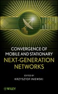
An illustration of the application of mobile and fixed WiMAX is provided in Figure 14.1. Mobile WiMAX is designed for users at vehicular speeds in urban environments. Provisions for mobile use particularly deal with handovers as the user moves from one cell to another, and they also deal with fluctuating throughput as channel conditions vary due to blockage and reflections.
Figure 14.1. Mobile WiMAX in OFDMA mode, and fixed WiMAX in OFDM or single carrier modes.
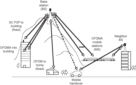
Figure 14.1 also illustrates other variants of the WiMAX standard that use single-carrier (SC) modulation for last-mile Internet connections and use OFDM for rural Internet connections.
The 802.16 standard splits the RF bands in two. The lower RF band ranges from 2 GHz to 11 GHz and the upper band ranges from 10 GHz to 66 GHz, with an overlap around 10.5 GHz.
This split is based on the availability of RF spectrum for broadband deployments in the United States, and it takes also other regulatory regions of the world into consideration. The split also considers that toward 10 GHz the benefits of OFDM diminish when compared to a much simpler SC system.
Table 14.1 provides a general overview of the RF spectrum and its suitability for WiMAX.
TABLE 14.1. Suitability of Radio Spectrum for WiMAX
Notes: VHF, very high frequency; UHF, ultra high frequency; SHF, super high frequency; ISM, Industrial, scientific and medical; UNII, Unlicensed National Information Infrastructure; WCS, Wireless Communications Service; MMDS, Multichannel Multipoint Distribution System; LMDS, Local Multipoint Distribution Service; UWB, ultra wideband; GPS, Global Positioning System.
14.1.4 PHY and MAC Components of a Broadband Mobile Air-Interface Standard
The 802.16 standard is an air-interface standard. This means that it describes protocols and methods by which compliant devices can communicate over an air channel. The protocols are grouped in two layers: the MAC layer and the PHY layer.
The PHY layer describes how data bits are transferred to and from radio-frequency (RF) waveforms. This involves the coding and modulation operations, error correction, the use of the RF channel, definition of the burst frame with preambles and pilots, and the use of schemes for multiple antennae. The PHY layers also includes digital signal processing (DSP) for filtering and equalization, as well as RF up- and down-conversion and analog filtering, but their design and specifications are not standardized and instead left to the vendor.
The MAC layer describes the type of connections available to a client of an 802.16 device, and it also describes how the client data are transformed to and from framed data for transmission and reception by the PHY. This involves establishing and maintaining connections between a base station (BS) and a mobile station (MS), assigning transmission slots to supply the desired data rate and Quality of Sevice (QoS), and dealing with temporary and permanent signal drops, encryption and security, and BS-to-BS hand-offs.
In the layer stack, the network communicates with the MAC through the link layer at the MAC service access point (SAP), and the MAC communicates with the PHY at the PHY-SAP. In some exceptions where BSs communicate directly with each other, management and control data can be shared over the backbone network, without traversing through the PHY.
The control over the settings in the PHY and the MAC is at the discretion of the operator. The operator has the task to balance the user’s QoS requirements against cost and revenue. Capital expenditures (CAPEX) involve the cost of deploying the BSs, and operating expenditures (OPEX) involve the cost of maintaining and servicing the network and the customers. Outages, cell coverage, and even power consumption of mobile devices play a role since they affect the user experience. The operator and device manufacturer must also be compliant with regulatory requirements regarding the use of licensed spectrum, sharing unlicensed or lightly licensed spectrum, and meeting spurious RF transmit emission requirements.
The standard supplies the options and protocols to establish and maintain RF connections between compliant devices. A device contains a vast amount of discretionary algorithms to set system parameters on a connection-by-connection basis. This includes PHY and MAC algorithms for choosing when to change modulation and coding settings, when to perform a hand-off, when to wake-up or put a device to sleep, and how to schedule data for user connections.
14.1.5 History of IEEE 802.16
IEEE 802.16 was originally designed for nonmobile, enterprise-class deployments. The development of the standard started officially in 1999, and it was completed in 2001 with a technical specification for the delivery of high-speed wireless data connections to businesses that would not have access to optical fiber connections. The RF ranged from 10 GHz to 66 GHz, and the system required outdoor antennae with line-of-sight (LOS) connections to a BS. The modulation was based on Single-Carrier Quadrature Amplitude Modulation (QAM).
In 2003 amendment 802.16a was completed, which included modulation with Orthogonal Frequency Division Multiplexing (OFDM) based on a fixed FFT size. This targeted the license exempt RF frequency bands in the 2- to 11-GHz range. These lower frequencies made the use of indoor antennae possible, allowing consumers to subscribe to 802.16-based data services. Indoor reception is heavily impaired by multi-path reflections from other buildings, and it causes frequency-selective fading. OFDM was applied to mitigate this impairment.
At sub-11-GHz frequencies, 802.16e (December 2005) provided for mobile services through the addition of mobile handover. A user device such as a cell-phone or portable data assistant (PDA) can establish and maintain a service connection across cell boundaries, even at high speeds. An overview of the standards and amendments is provided in Table 14.2.
TABLE 14.2. Overview of Select IEEE 802.16 Standards and Amendments
| 802.16.1 | LMDS | Became 802.16-2001 Wirel essMAN-SC. |
| 802.16-2001 (1999–2001) | WirelessMAN-SC (Single-carrier TDMA) |
Line-of-Sight, fixed outdoor antenna, RF frequency above 10 GHz, >100 Mbit/s fiber extension. |
| WirelessMAN-SCa WirelessMAN-OFDM (256 subcarriers) WirelessMAN-OFDMA (128, 512, 1024 and 2048 subcarriers) |
Three PHY alternatives for urban wireless DSL service. Below 11-GHz non-line-of-sight (NLOS) deployments use OFDM (256 sub-carriers) and OFDMA (2048 sub-carriers). Line of sight (LOS) uses single carrier “SCa”. | |
| 802.16.2-2001 (1999–2001) | Recommended Practice for WirelessMAN-SC | Recommendations for operators in licensed bands to deal with co- and adjacent channel inteference, above 10 GHz. |
| 802.16c (2002) | Profiles for 802.16 | These are the original profiles, developed with help from the WiMAX Forum. The amendment has now been superseded by activities in the WiMAX forum. |
| 802.16a (2000–2003) | WirelessMAN-SCa WirelessMAN-OFDM (256 subcarriers) WirelessMAN-OFDMA (2048 subcarriers) |
Split PHY, OFDM(A) under 11 GHz for indoor and nomadic use, and SC-TDMA above 10 GHz. Single MAC. Licensed and unlicensed bands. |
| 802.16.2-2004 (2001–2004) | Recommended Practice for WirelessMAN-OFDM and WirelessMAN-OFDMA | Recommendations for operators in licensed bands to deal with co- and adjacent channel inteference, below 11 GHz. |
| 802.16d (2004) | Originally: Profiles for 802.16a, under 11 GHz. Later abandoned in favor of a full revision | “Fixed WiMAX” |
| 802.16-2004 | Full revision, merging 16a, 16c, 16-2001 | |
| 802.16e (2002–2005) | WirelessMAN-OFDMA (128, 512, 1024 subcarriers) | Combined fixed/mobile. “Mobile WiMAX” includes uplink MIMO, scalable OFDMA, and hand-off |
| 802.16h (2004–2009) | License exempt (LE) | Standardized schemes for improving the use of radio resources (RF channels) in license exempt bands, considering other users in the same channel. |
| 802.16j (2004–2009) | Mobile multihop relay (MMR) | Additional capabilities to form a network comprising a single multihhop relay base station (MR-BS), one or more relay stations (RS), and a multitude of mobile stations (MSs) |
| 802.16f-2005 | Management information base | MIB and MPPS are used to manage the devices in the network. |
| 802.16g-2007 | Management plane procedures and services | |
| 802.16-2009 (2007–2009) | Second revision (REV2) | Obsoletes 802.16-2004 and 802.16e-2005 and several other corrections and amendments. Started as errata fixes, but now covers all amendments except “h” and “j”. |
| 802.16m (2006–2010) | Advanced interface | Originally a candidate for IMT-Advanced (4G), competing with LTE. Offers improved spectral efficiency, reduced latency, increased user density, and enhanced localization techniques for emergency services. |
14.1.6 Mobile Versus Fixed WiMAX
The essence of WiMAX is captured in the definition of its Medium Access Control (MAC) layer.
In the original standard, its task was to supply users with a several levels of QoS for carrier-quality, enterprise-based telecommunications services. The 802.16 BS offers classes of QoS to support services such as T1/E1 guaranteed rates, high-throughput low-latency video conferencing, low-throughput low-latency Voice over IP (VoIP), and a best-effort Internet connection service.
The core of the MAC comprises self-correcting request and grant protocols, and multiple connections per user terminal. The MAC provides an efficient protocol for bursty data that can easily handle high peak data rates in a fading medium.
In the standard there is a distinction between Nomadic use and Mobile use.
In fixed use the operator configures a user for one specified cell or cell sector only. This is usually sufficient for Point-to-Point (P2P) broadband services to a residence or business, but there are no provisions in the protocol for a user to dynamically associate with just any of the operator’s BSs and negotiate a desired data rate.
Nomadic use implies that the user can and may connect to a different BS or a different sector of a same BS and expect to be recognized and accepted by the operator automatically and promptly. Standard 802.16-2004 specifies how a connection between a BS and an MS is requested by the MS and accepted and managed by the BS. The standard also provides management messaging and access schemes that allow the BS to manage a variable load of MSs in its cell or any of its cell sectors. This is a Point-to-Multipoint (P2M) architecture.
Quality of Service factors such as data rate, latency, and availability are usually not guaranteed during nomadic movement, and the connection may have to be reestablished from scratch. Moreover, the quality of the connection may be impacted significantly during motion, even if the user remains within the cell or sector of a single BS. This is of course not acceptable for cellular voice applications.
Mobile use brings a much tougher requirement: to uphold the connection and data transfer as the user moves, even if the user transitions from one cell or cell sector to another. This involves cell-to-cell or sector-to sector hand-off schemes with sophisticated interactions between the MS and multiple BS, in order to uphold the QoS.
Modulation and coding schemes are optimized for mobility, and they minimize the error rate during motion within a sector or cell. This covers Doppler frequency shifting effects and temporary fading effects at pedestrian and vehicular speeds.
A further change in the mobile version of the standard is the introduction of Scalable OFDMA (S-OFDMA). The “e” amendment provides several options for the FFT size, and this allows the operator to configure the FFT based on channel width. The subcarrier spacing and the symbol duration can be optimized for the RF channel propagation conditions.
Notable features of the “e” amendment for mobility are as follows:
1. Additional OFDMA FFT sizes of 128, 512, 1024, and 2048. This allows the OFDM bandwidth to scale with the channel bandwidth while keeping the subcarrier spacing and the symbol duration independent from the channel bandwidth.
2. Adaptive Modulation and Coding (AMC) in subchannels, to benefit from sections of the channel with notably good SNR performance.
3. Hybrid-Automatic Repeat Request (ARQ) for more efficient use of the Forward Error Control (FEC) schemes during error bursts in mobile fades.
4. Multiple-Input and Multiple-Output (MIMO) diversity for better uplink (UL) cellular throughput.
5. Reduced latency for mobile hand-offs.
6. Sleep modes to extend battery life.
The WiMAX burst-type modulation scheme in the “e” amendment significantly improves data downloads (e.g., web browsing) when compared to cellular standards rooted in voice applications.
14.1.7 WiMAX Forum
The objective of an open standard is to enable independent manufacturers to bring interoperable devices to market. The IEEE standard describes all the details of the technical aspects of interoperability. This includes all types of overhead messaging, frame formats, signal properties, and modes of operation.
The WiMAX Forum is a nonprofit consortium comprising (a) system vendors and (b) component and device suppliers and operators. It provides a certification process for conformance and interoperability. Conformance tests are performed by specialized and certified third-party conformance labs, which test systems against the Radio Conformance Tests (RCT) issued by the Forum. Interoperability tests are performed at so-called wireless “plug-fests.” To pass an interop test, a vendor must succeed with at least two others during BS and MS connection tests. For any vendor, the goal of these tests is to provide confidence in operators and consumers that its equipment can be mixed and matched with equipment from other vendors.
Table 14.3 specified the channel width, duplexing scheme and the FFT size for various RF bands per the WiMAX Forum System Profiles. These parameters are explained in more detail in later sections.
TABLE 14.3. WiMAX Forum System Profile Specifications
| Band | Channel | Duplexing |
| WCS 2.3 GHza | 2 × 3.5 MHz, 2 × 5 MHz, or 2 × 10 MHzb,c | FDDd |
| 2.3–2.4 GHz (global spectrum) | 1 × 8.75 MHz, 1 × 5 MHz, or 1 × 10 MHze | TDD |
| 2.3 GHz (global spectrum) | 1 × 3.5 MHz, 1 × 5 MHz, or 1 × 10 MHz | |
| 2.5 GHz | 2 × 5 MHz or 2 × 10 MHz | FDD |
| 2.5 GHz | 1 × 5 MHz or 1 × 10 MHz | TDD |
| 3.3–3.4 GHz | 5 MHz | TDD |
| 3.4–3.6 GHz | 2 × 5 MHz, 2 × 7 MHz or 2 × 10 MHz | FDD |
| AWS 1.7 GHz UL and 2.1 GHz DLa | 2 × 5 MHz or 2 × 10 MHz | FDD |
| 700 MHz | 2 × 5 MHz or 2 × 10 MHz | FDD |
| 700 MHz | 1 × 5 MHz, 1 × 7 MHz or 1 × 10 MHz | TDD |
a AWS is Advanced Wireless Services, and WCS is Wireless Communications Service (both North America/FCC).
b 2× refers to uplink (UL) plus downlink (DL) pairing.
c 512-pt FFT for 5-MHz channels, 1024-pt FFT for 7, 8.75, and 10 MHz.
d For FDD duplex channels, the BS must support FDD, and the MS must support H-FDD.
FDD support for MS is not required.
e 8.75 MHz is for WiBRO. This is Mobile WiMAX at 2.3 GHz, with 8.75-MHz channelization used in Korea.
14.2 MAC OVERVIEW
The MAC manages the traffic load for all user applications, over the physical medium. The PHY is responsible for transmitting and receiving information bits across the air-link, and it has no knowledge of the specific performance requirements for different types of application data.
In 802.16, an MS establishes multiple independent connections to and from a BS to transfer data. To exchange data units, a connection identifier (CID) is used to address data and management traffic between the BS and its MSs.
The MAC manages the network entry of a station, and it establishes connections to transport data. The MAC also implements the convergence sublayer, which maps higher layer addresses such as IP addresses of its service data units to the individual stations served. An MS communicates with a BS through multiple concurrent connections, covering MAC management, initial ranging, user data, bandwidth requests, idle payload padding, and broadcast information.
14.2.1 MAC and PHY Protocol/Service Data Units (PDU/SDU)
The data at the input of a layer is called a service data unit (SDU), and the data at the output of a layer is called the protocol data unit (PDU).
The MAC encapsulates its input SDU (the MAC-SDU, or MSDU) with all necessary framing headers so that the peer MAC at the receiver can process the MAC payload data. The processing by the MAC includes data encapsulation, aggregation, and fragmentation and managing the PHY.
Its output is the MAC-PDU, or MPDU, which is then passed to the PHY as the PHY-SDU (PSDU). The PHY adds any headers and overhead necessary for synchronization and signal decoding, and it transmits the PHY-PDU (PPDU) over the air to the PHY at the receiver end. There, the process is inversed, and ultimately the data are presented to the link layer as a received MSDU. An MPDU consists of a MAC header, optional payload data, and an optional CRC.
The link from the BS to the MS is called the downlink (DL), and the reverse link is called the uplink (UL).
The standard contains hundreds of pages describing the MAC schemes, and the reader is referred to the text for details.
14.2.2 Scheduling Versus Collision Avoidance
The MAC schedules its users based on their traffic load requirements, their QoS requirements, and the conditions of the air link. The BS probes each MS for its capabilities in terms of coding and modulation options, MIMO options (discussed later), and other MAC and PHY options, and it schedules the MS based on the reported capabilities and limitations.
Once the scheduling is completed and communicated to the MS, there are no further air-link resources wasted in arbitration or collision recovery. There is of course some scheduling overhead, and it is the object of the standard to minimize it. To accomplish this, the MAC can reduce header overhead and aggregate short MAC SDUs (e.g., short 40-byte TCP acknowledgment packets). It can also maximize frame utilization by allowing the fragmentation of large MSDUs (e.g., 1-kbyte TCP packets) in order to top-up even small unused parts of the frame.
In contrast, Carrier Sensed Multiple Access Collision Avoidance systems (CSMA-CA) generally do not schedule their users. Stations are required to monitor the channel and avoid collisions with existing transmissions. Congestion challenges arise when multiple transmitters sense that the channel is carrier-free and start their transmissions simultaneously. Despite mandatory sensing, these systems still have to deal with collision rates as high as 30–40% in even lightly loaded systems.
Nevertheless, its simplicity and its lack of a central scheduling entity make CSMA-CA attractive for data-centric applications such as the Wireless Local Area Network, popularly known as WiFi (IEEE 802.11). In WiFi, access points (APs) form a network with their stations, but APs generally have to share the channel with other APs. The network usually tolerates the high collision rates because the channel mostly offers abundant capacity for retransmissions. Collision schemes are used where there is no central entity such as a base station. Service is often without commitment “as-is,” “where-is,” and “when-is.”
In contrast, mobile voice applications with high traffic volumes, high number of simultaneously connected stations, and high costs of RF band licensing make this not a viable candidate for a subscription-based cellular standard. Centralized scheduling is a necessity.
14.2.3 Quality of Service (QoS)
One task of the MAC is to make sure that user applications receive their subscribed Quality of Service. The Quality of Service (QoS) refers to guarantees for a minimum throughput and maximum latency for application traffic in a network. Offerings are priced for different levels of QoS.
Different applications have different demands. For instance, voice traffic has tight demands on latency. Excessive delays of the transferred signal between two ends of a call would literally result in irritating echoes. Moreover, variations in the delays, also called jitter, would cause distracting audible voice echoes due to limitations in the delay-tracking ability of the echo cancelers in voice systems. On the upside, voice is quite tolerant to packet losses and high bit error rates. This is different for real-time video, where data rates are high, latency is also low, and the tolerance to packet loss and jitter is moderate. Traffic such as Internet file transfer has practically no requirements for the rate or latency at which it is transferred, as long as bit error rates are not too high for the application layer to handle.
In wireless systems, QoS must be delivered by the MAC under fluctuating levels of capacity of the channel at the PHY. The task of the scheduler is to allocate user slots in data frames. Under mobile wireless conditions the channel fluctuates dramatically and often unpredictably, and the scheduler relies on many support mechanisms in the PHY to offer the MAC as much throughput as possible. In contrast, QoS in wired access systems is much simpler to implement at the MAC bacause it is based on a fixed-capacity PHY channel.
Quality of Service (QoS) is native to 802.16, and it is modeled after QoS in ATM (Asynchronous Transfer Mode) with some modifications based on DOCSIS. The Data Over Cable Service Interface Specification (DOCSIS) included QoS in its 1999 version, and it is designed for high-speed data transfer on Cable TV systems.
Traffic offered to the MAC is classified with service flow identifiers (SFIDs) for QoS and is then mapped to connection identifiers (CIDs) for scheduling, modulation, and coding.
QoS in 802.16 covers over-the-air service levels in terms of—among other things—minimum and maximum sustained rates, reserved rates, tolerable minimum rates, jitter, and latency. There are four (plus one) service flow classes:
1. UGS (unsolicited grant service) for constant bit rate (CBR) requirements as used by legacy Public-Switched Telephony Network (PSTN) systems based on Time Domain Multiplexing (TDM), e.g., DS0 and T1/E1 TDM. In these systems, the data rate is constant even during silence on the line.
2. rtPS (real-time polling
service) for real-time variable bit rate (rtVBR) requirements, where
multiplexing is done statistically based on increasing, decreasing, and bursty
demands for data rate in real-time applications such as Voice over IP (VoIP) and
streaming video. The compression and codec algorithms in these applications
(such as MPEG) will demand higher data rates or relax to lower rates, depending
on the underlying video or voice signals. In the UL, the BS schedules UL bursts
explicitly on demand, based on the subscriber’ s burst requests (BRs).
A variant, extended rtPS, provides regular UL scheduling with less BR overhead,
as in UGS, but with dynamic allocations as in rtPS.
Extended rtPS (ertPS) has
been added because the longer frame durations of OFDM and OFDMA versus SC
created the need for a scheduling mechanism between UGS and rtPS to accommodate
VoIP with reasonable jitter.
3. nrtPS (non-real-time polling service) for non-real-time variable bit rate (nrtVBR) requirements, where multiplexing is done statistically with a minimum guarantee of rate, but where there is no real-time delay or jitter specification.
4. BE (best effort), for applications with no minimum throughput guarantees over some specified short-term time span.
The Service Level Agreement (SLA) promises data rates in a statistical sense, depending on the class required for each application. In setting the SLA data rates, the operator takes into consideration the location and type of subscribers. By considering their device capability (cost and complexity) and location of use (distance and obstructions), subscribers that can communicate at high rates can be promised higher levels of service.
14.2.4 Network Entry
A further task of the MAC is to manage the network entry of subscribers.
When an MS intends to join the network, the BS has no knowledge of its service needs, and it has of course no scheduled slots for its UL transmissions. To obtain entry, a number of unscheduled exchanges with the BS must first be completed, followed by some scheduled exchanges.
14.2.4.1 Scanning, Synchronization, and Authentication.
When an MS powers up, it scans RF channels for a suitable BS to establish connections. To this end, an MS is shipped with a list of channel frequencies to scan. This list resides in the driver SW or in a SIM card supplied by the operator.
Scanning is not without challenge. It is possible that the MS simultaneously receives strong DL signals from multiple BS. This can easily happen in a single-frequency deployment or at the cell edge in a multifrequency deployment. Thanks to a pseudo-noise sequence in the downlink preamble transmitted by the BS, the MS can distinguish between multiple overlapping BS cells by correlating the received preamble sequence with a set of locally stored reference sequences. Although reception is heavily interfered, it can still select the strongest signal and establish a connection.
After scanning, the MS receiver synchronizes with the DL frames. This involves RF center frequency adjustments, as well as time alignment of the base band decoder.
After frame synchronization, the MS decodes the broadcasted Uplink Channel Descriptor (UCD) message and uses the supplied information about the frame to start initial ranging. The MS coarsely synchronizes its UL transmission with the UL frame, and it selects a transmit power level based on the power level received from the BS and any additional power information in the UCD. The MS also determines the initial ranging transmission slots from the UCD, and it starts its first transmission with a ranging request to the BS.
This transmission occurs in a special contention-based ranging channel, using Code Division Multiple Access (CDMA). The MS transmits MAC messages without allocation by the BS, but this flexibility comes at the expense of efficiency. CDMA reception quality degrades only slowly and gracefully as the number of overlapping transmissions increases, without coordination or scheduling with other transmitters. In contrast, OFDMA is more bandwidth-efficient but does not tolerate overlaps (collisions) at all.
As part of the ranging response, the BS responds with any further required power adjustments, as well as frequency and frame alignment adjustments to be made by the MS. These fine tunings are directed by the BS to enable the MS to proceed with scheduled communications without interfering with other MS served by the same BS.
14.2.4.2 Authentication.
Authentication proves the identity of the MS to the BS. This matters for user-specific parameters related to service agreements and billing. Since user data are shared over the air, which is a notoriously nonsecure medium, encryption is used to warrant privacy and protect identity. The BS recognizes the MS by its 48-bit MAC address, and authentication follows through Privacy Key Management (PKM) messages. With PKM, the MS communicates its X.509 certificate during the Security Association (SA). X.509 (1988) is an ITU-T cryptography standard for a public key infrastructure, based on a strict hierarchical system of Certificate Authorities (CAs). In 802.16 the certificate belongs to the manufacturer of the MS.
Data are encrypted using private traffic encryption keys, which are communicated between MS and BS using DES3, AES, or RSA public encryption schemes.
14.2.4.3 Periodic Ranging.
Due to fluctuating conditions of the air link, which is typical in mobile conditions, the BS will periodically instruct the MS to adjust its power level, RF carrier synchronization, and frame alignment. These adjustments are performed as part of maintenance ranging, also called periodic ranging.
The BS uses periodic ranging to minimize the interference from the MSs it serves. Incident signals from simultaneously transmitting MSd must have receive power levels that are as close together as possible across the subcarriers. The MS transmit level is adjusted based on the power level received by the BS, and thus it automatically accounts for distance and obstructions.
Fine frequency adjustment messages correct for any clock and carrier mis-tunings by the MS, as well as any offsets caused by the Doppler velocity between different MSs. Frame adjustment also corrects for differences in propagation delays of signals from MSs, which are due to their different distances from the BS.
Maintenance ranging is also used to adapt to changing properties of the air channel. For instance, at 802.16 frequencies above 11 GHz, used in rural or suburban areas, weather and wind conditions play a role (foliage, rain, snow), and at 802.16e frequencies under 6 GHz it is mobility of the SS or even the mobility of obstructions (moving vehicles, bridges, tunnels) that play a role.
The BS performs unsolicited periodic ranging if there are no data to communicate to or from the MS. By keeping the power level and synchronization current with a dormant MS, link disruptions are avoided. This allows for a renewed demand for data exchange to ramp-up quickly without reestablishing the connection.
To this end the BS allocates bandwidth for the MS, even though the MS has no demand for it. This is called an unsolicited grant (UG). The MS responds with idle data in the frame pad bits, and the BS evaluates the received signal to perform periodic ranging.
Periodic ranging is also used to maximize battery life in mobile subscribers. The BS can instruct an MS to reduce its transmit power if the volume of data by the MS does not require high modulation rates. With SNR to spare at lower modulation, the RF transmit power is reduced and the battery life is extended. Moreover, transmit power levels of stations at the cell edge can be adjusted through ranging to reduce inter-cell or inter-sector interference.
14.2.4.4 Sleep Mode.
Another method to reduce battery power draw by an MS involves sleep mode. The MS negotiates periods of absence from the BS during which the BS will not send any requests or any data to the MS. The MS powers down its RF and DSP subcircuits for transmission and reception, and they only operate a minimal state machine plus timer. Once the scheduled sleep period (or sleep window) is over, the MS will decode the following frame and its service flows will be available without any re-negotiation.
14.2.4.5 Idle Mode.
When an MS has no traffic to transmit but is available for DL traffic, it can switch to idle mode. During idle mode the station is not registered with any specific BS, which means that there is no need to manage hand-offs. In the event of DL traffic, for instance for a pending VoIP call or text message, the BS will use paging to reach the MS.
14.2.4.6 Bandwidth Request.
To start a transmission, for instance to initiate a call or an internet data request, a MS issues a bandwidth request (BR) and receives grants from the BS. The MS also uses BR to increase or decrease bandwidth, depending on its application demands.
The BS allocates symbol and subchannels to a MS, and this is broadcast to all MSs in the UL-MAP. The MAP also defines the modulation and coding rates for the MS transmit burst profile.
The norm is to allow MSs to use the CDMA ranging channel for BR, or to allow an MS to piggyback a BW request subheader when transmissions are already ongoing.
The BS can also poll its subscribers for BRs. Polling is generally done one-on-one (unicast), but this may be inefficient if there are many inactive MSs. These inactive stations are better polled through a multicast to a group or through a broadcast to all, or they are left to use ranging as needed.
The BS can also schedule multiple subscribers to receive a common signal for common data. This is called a multicast connection. It improves the frame efficiency in terms of the number of connections, but the connection throughput must be lowered to meet the highest rate that all stations in the multicast group can receive.
14.2.4.7 Basic Capability Negotiations.
The BS considers the capability limitations and other operational constraints of each MS. These limitations are communicated to the BS during basic capability negotiations.
Cost and size restrictions of devices limit certain capabilities. For instance, modulation rate is often limited by RF distortion specifications of a device. The supported coding techniques are limited by the DSP capabilities. The transmit power is limited by the supplied power amplifier. And the MIMO options are limited by the number of antennae of the device.
To maximize the cell throughput, stations with common capabilities are grouped together in a particular section of the frame, called a zone. Zones are also used to manage interference in the same cell and in neighboring cells.
14.2.5 Mobility Management: Handover
A significant new feature in mobile WiMAX (over the fixed variant) is mobility management. Hand-off refers to the transition of a user from one serving BS to another while maintaining connectivity and QoS. Hand-off delays are kept below 50 ms.
The BS advertises the network topology to its MSs by broadcasting the UL and DL channel descriptors (UCD and DCD) of neighboring BSs. This means that the MS does not have to interrupt the connection and leave the BS to scan and decode possible alternate channels.
The MS determines the SNR and RSSI for signals from neighboring BSs during a scanning interval assigned by the serving BS. The MS may also use this interval to associate with a selected target BS before leaving the current serving BS. Two BSs can even communicate over the backbone network to expedite ranging of the MS with the target BS.
There are three handover variants. In hard handover (HHO) the MS maintains its connections exclusively with the serving BS throughout the handover. After establishing context with the target BS of choice, the MS simply terminates its context with the previous serving BS.
A second variant is macro diversity handover (MDHO), which allows a MS to maintain a list of preferred BSs, called the active set. The active set is chosen by the MS, and it is based on the signal quality from neighboring BSs as in HHO.
All data to and from the MS is transmitted to and from all the BS in the active set simultaneously. This comes at the cost of frame inefficiency, but it is temporary and it provides spatial diversity. One BS, in the set, the anchor BS, provides the necessary scheduling and coordination. At the cell edge the MS can easily maintain its connection to the network as signal conditions with any BS improve and deteriorate. Once the air link is stable and in favor of one particular BS, the multiple contexts are reduced back to a single context in favor of freeing resources in the frame.
A third variant is Fast Base Station Switching (FBSS). The MS maintains connections with multiple BSs, as in MDHO, but only one BS transmits or receives at a time. There is no spatial diversity, but the MS can rapidly switch between BSs of an active set depending on changing signal conditions.
14.2.6 Fragmentation and Packing
In a cellular communication link, the RF link quality will vary over time, and even with sophisticated rate adjustments and resource scheduling, it is inevitable that packets of data will be in error. The target packet error rate is in the range of 0.1% to 1%, which often corresponds to a bit error rate (BER) of 1e-4 to 1e-5. Compare this to a wired communication link, where a BER of 1e-6 to 1e-10 and even lower is desired.
The MAC delivers a BER to the link layer that is at least 100-fold greater than the BER at the PHY. To this end, there are provisions for retransmissions. This includes a data integrity acknowledgment between the two MACs at either end of the connection, as well as means to buffer and possibly retransmit errored data.
The MAC can fragment and pack link-layer packets. Packets larger than 1500 bytes (e.g., large IP data packets) are often fragmented into smaller pieces, and packets as small as 40 bytes (e.g., IP acknowledgment packets) are often packed into a larger MPDU. This offers better efficiency in error recovery, better QoS management and it helps maximize cell throughput.
Fragmentation subheaders (FSH) and packing subheaders (PSH) supply the necessary overhead to reassemble the received data unit.
14.3 PHY OVERVIEW
The physical layer of the standard covers the technical details to modulate signals for communication through the Over-the-Air (OTA) channel. The PHY covers OFDM modulation, coding, MIMO and provisions for synchronization.
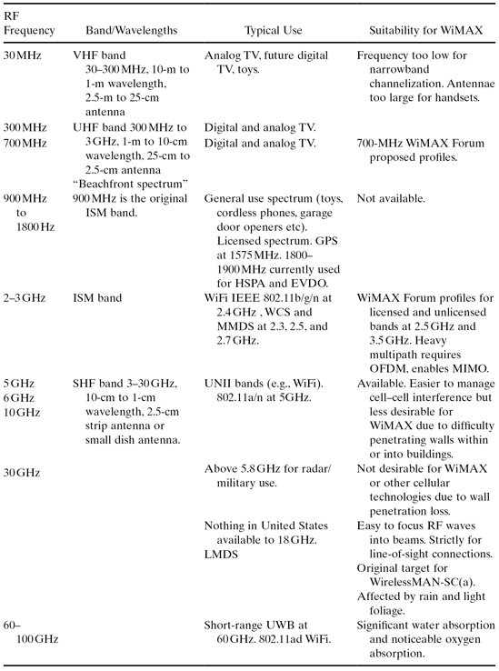
Figure 14.2 shows a generalized block diagram of a WiMAX modem device, covering the major RF and digital/analog baseband circuit groups. The standard does not specify how to design the circuits or how to partitioning the required functionality. Instead, it specifies the required behavior and performance of the ultimate transmit and receive systems. The vendor chooses between several RF, analog and digital architectures and partitions depending on specific market needs.
Figure 14.2. Generalized block diagram of a WiMAX modern device, covering the major RF and digital/analog baseband circuit groups.
14.3.1 Uplink/Downlink Duplexing
The duplexing scheme defines how the downlink (DL) transmissions are separated from the uplink (UL) transmissions.
WiMAX has three duplexing methods:
1. In time division duplexing (TDD), the UL and DL are time multiplexed, which allows the use of a single channel for both directions. To this end the OFDMA frame is split between a DL subframe and a UL subframe. The typical DL : UL split is 26 : 21 symbols in a 5-ms frame. Frame duration and split are generally not varied during operation.
2. In frequency division duplexing (FDD), the UL and DL occur in two different channels. The BS transmits in one FDD channel while the MS simultaneously transmits in the other.
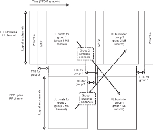
3. In hybrid FDD (also called half-FDD), a BS can service a mix of FDD and non-FDD stations. The BS is full-FDD, while some MSs are FDD and some are non-FDD. The non-FDD stations do not transmit and receive simultaneously. They operate as in TDD, but with UL and DL in different RF channels.
Figure 14.3 shows the OFDMA frame structure for TDD systems, and Figure 14.4 shows it for hybrid FDD systems. In TDD systems the station at either end must switch from reception to transmission within specified times, called the transmit turnaround gap (TTG) and the receive turnaround gap (RTG).
Figure 14.3. OFDMA frame structure for TDD systems.
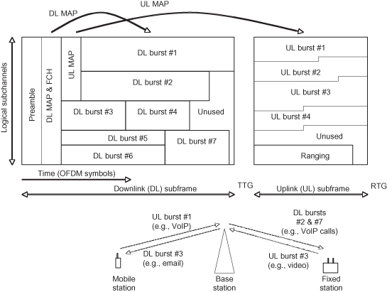
Figure 14.4. OFDMA frame structure for hybrid FDD systems.
14.3.1.1 TDD Systems.
In contrast to voice traffic, data traffic has significantly more DL traffic than UL traffic. In TDD systems, this asymmetry in demand is easily managed by flexibility in the DL : UL split. In older deployments where traffic is dominated by voice communications, a permanent ratio around 1 would be a good fit, because UL voice has the same data rate requirements as DL voice.
A variable split also allows more flexibility when mixing low-power transmitters with high-power transmitters. Compared to a low-power MS, a high-power MS requires less time to transmit a same amount of data, since it can operate at a higher rate thanks to the higher SNR it delivers at the BS. Thus the optimal split may depend on the mix as well as on the traffic.
Cellular deployments require careful management of interference between cells. This is particularly important in single-frequency deployments, in which an operator occupies only one channel across multiple cells. In TDD the UL and DL subframes between neighboring cells must be synchronized. When an MS at the cell edge receives a DL signal, a nearby MS connected to a neighboring BS should not be transmitting. By agreeing on a split, different operators can synchronize their frames and minimize interference.
The TDD ratio may be adapted depending on the SNR conditions and the bandwidth demands. This technique is called ATDD (adaptive TDD), but if any adjustments are needed, they must be slow varying to best serve the network as a whole.
TDD devices are simpler than FDD devices in terms of RF circuitry, but they require more DSP complexity. The TDD device has simpler RF filters and only one RF oscillator. The DSP and RF however must manage rapid turnarounds and re-synchronizations. With falling silicon process costs, this disadvantage is becoming insignificant.
TDD is required in unlicensed bands to ensure coexistence with other IEEE devices. A TDD receives in the same channel as it transmits, and thus it can Listen Before Talk (LBT) and avoid interference caused by transmission collisions.
As an aside, in TDD the user can still speak and listen simultaneously during a voice call. The TDD frame rate is rapid enough that DL/UL multiplexing of fragments of voice data remains transparent to the user.
14.3.1.2 FDD Systems.
FDD is required in some licensed bands, as these bands were originally specified for the first cellular voice standards. The existing voice bands are an attractive replacement market for WiMAX. The frequency allocations for FDD systems are symmetric, meaning that there is equal bandwidth available for both UL and DL. The DL : UL ratio is thus fixed because the channel bandwidth is fixed, and this offers less flexibility than a TDD system.
Duplex spacing varies significantly for the different bands. In some it is as small as 60 MHz (PCS) or as much as 400 MHz (AWS).
FDD requires stations to transmit and receive at the same time. In comparison to previous voice-based FDD systems that have an unframed “continuous PHY,” WiMAX FDD is framed, which provides regular scheduling information at predictable times.
Regardless of the standard, an FDD device must ensure that reception (say at −80 dBm) is not interfered by spurious emissions from its own transmissions (say at +15 dBm) in the alternate duplex channel. This requires the use of fairly large and lossy duplex filters. The filters must be placed after the power amplifier, and their insertion losses can result in significant degradation to battery lifetime. It is not unusual for half of the power delivered from a power amplifier to be dissipated as heat before reaching the antenna.
In contrast, the TDD transmitter and receiver are not on at the same time. The filter is replaced by a simple switch, which connects the transmitter and receiver to the antenna. This reduced the component count and insertion losses.
14.3.2 OFDM and OFDMA
The signal modulation scheme in WiMAX is based on Orthogonal Frequency Division Multiplexing (OFDM). Whereas a traditional single-carrier (SC) modulation scheme occupies the complete physical RF channel with a single high-rate stream of modulated bits, in OFDM the channel is first subdivided into multiple subcarriers, and each subcarrier is individually modulated at a lower rate.
14.3.2.1 OFDM: Modulation.
Already in 1966 it was shown that OFDM could solve signal impairments caused by multipath impairments, and in 1993 it was adopted for high-speed Digital Subscriber Line (DSL) modems that operate over regular twisted-pair phone lines. In 1999 the IEEE LAN amendment 802.11 (WiFi) adopted OFDM for the 5-GHz 802.11a amendment, and later in 2003 it is also adopted it for 2.4 GHz in the 802.11g amendment. OFDM is also adopted by 802.15 for ultra-wide-band (UWB) systems at high rates and short distances.
An SC-modulated signal can theoretically supply a given symbol rate in a channel of about equal width. The number of bits that are carried by a symbol depends on the modulation order.
An OFDM-modulated signal will yield about the same bit rate but at a much lower symbol rate. To simplify the OFDM processing at the transmitter and receiver, an FFT is used to modulate each subcarrier independently. For instance, a 20-MHz channel is divided into 2048 subcarriers, each with a width of about 10 KHz. The symbol duration is thus 100 µs. This is orders of magnitude longer than that in the SC case.
OFDM is the preferred modulation when the channel has significant multipath interference, since it can combine very low symbol rates with very high data rates. With reflections from other buildings and inside walls easily reaching 10-µs delays, the symbol duration must be long enough to absorb most of the resulting intersymbol interference (ISI).
Single-carrier modulation under these conditions would require impossibly complex equalization to overcome the ISI. In OFDM, however, the ISI is canceled simply by removing a small and designated fraction of the symbol that is affected by it. This fraction is called the guard interval (GI) or cyclic prefix (CP). The remainder of the symbol is practically void of ISI, and it merely requires a simpler form of equalization to help the decoder.
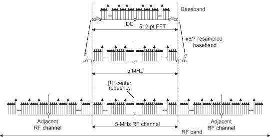
The OFDM symbol is illustrated in Figure 14.5. Figure 14.6 shows how an OFDM signal occupies a designated 5-MHz WiMAX RF channel.
Figure 14.5. OFDMA symbol.
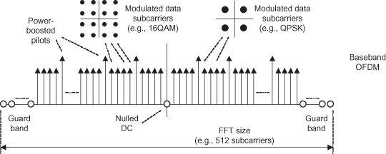
Figure 14.6. OFDMA signal occupying a designed 5-MHz WiMAX RF channel.
14.3.2.2 OFDMA: Access Multiplexing.
It is the responsibility of the BS to multiplex its users and provide them access at their required data rate and QoS.
The access scheme has two parts: a physical part at the PHY layer and a management part at the MAC layer. The OFDMA scheme refers to the PHY layer, and it defines how distinct connections share the physical air medium while communicating with a BS.
In Orthogonal Frequency Division Multiple Access (OFDMA), stations share the medium by accessing the medium only in designated short slots of time and narrow slices of the channel.
By contrast, in Time Division Multiple Access (TDMA), a station has disposal over the entire channel during a designated timeslot. For typical user data rates it is very inefficient to allot an entire 5-MHz band to one user, no matter how short the burst of time. Short transmit bursts require power amplifiers that transmit over a wide channel, at a high power level, and over a short time. This makes it very difficult to design for high power efficiency and manageable distortion. Moreover, the receiver is unduly burdened with synchronizing and decoding an unforgiving short data burst.
In Frequency Division Multiple Access (FDMA) a station has disposal over a designated subchannel at any time. This is also quite inefficient in cellular deployments, since FDMA requires minute guard bands between each connection. This wastes too much spectrum for the typical number of users serviced. OFDM does not require guard bands between subcarriers, since the subcarriers are phase-locked and orthogonal. Moreover, FDMA does not lend itself for efficient scheduling of bursty user data, no matter how narrow the subchannel.
OFDMA in Mobile WiMAX builds on concepts of TDMA, FDMA, and OFDM.
Before the advent of OFDMA, WiMAX used OFDM to efficiently use the available bandwidth, and connections were scheduled in a TDMA fashion. OFDM with TDMA overcomes some of the drawbacks of TDMA and FDMA.
OFDMA provides a further flexibility for sharing the channel, to more efficiently support a high number of stations with mixed data rate requirements.
14.3.3 Subchannels
The OFDM PHY in 16a describes fixed broadband deployments using OFDM combined with subchannelization. This is a precursor to OFDMA because it can be viewed as a coarse level of OFDM access. Subchannelization is still present in OFDMA and a brief overview is warranted.
In 16a the RF channel is split in groups of 12 subcarriers, which amounts to 1/16 of the total number of usable subcarriers in a 256-pt FFT (edge subcarriers are not usable). Given a limited amount of transmit power, there is a 16× (12 dB) SNR gain when transmitting in only one subchannel rather than in the whole channel. However, the channel is ever only occupied for one user (in TDMA fashion), and so subchannelization reduces the data rate to the subscriber, and ultimately throughput within the BSs cell. Nevertheless, the SNR boost is cautiously used to overcome temporary “rain fades” during adverse weather.
Subchannels are also used to boost range and increase the service area, where low connection numbers allow the allocation of more TDMA to a particular user to offset the cut in channel width.
In the UL, OFDMA overcomes the throughput limitations of TDMA by allowing multiple MSs to transmit at the same time. Interference is avoided by scheduling different subcarriers for different MS connections. Subchannelization is implemented by restricting the scheduling to a subset of subcarriers.
Transmissions over a fraction of the channel, but over a longer period of time, are preferred for the MS. This improves the SNR at the BS, for a given low amount of transmit power radiated by a battery-powered MS. These transmissions are sometimes loosely called “long and thin,” named after their occupation of the OFDMA frame.
For power efficiency in the MS receiver it is better to schedule the MS over the shortest possible DL time. This requires the use of the widest possible channel, but it minimizes the receiver on time. It is sometimes loosely called “short and fat.” The power amplifiers of a BS transmits at perhaps 40 dBm, which is much higher than a battery-powered MS at perhaps 20 dBm. In the DL, the SNR received at the MS is thus already higher, and “short and fat” is quite feasible.
14.3.4 Scalable OFDMA (SOFDMA)
Scalable OFDMA refers to the adjustment of the FFT size of a device depending on the width of the channel in which the device is deployed.
The intent of the adjustment is to tightly control the subcarrier spacing for mobile use. The spacing affects several core device specifications (at RF and for the DSP), and it has direct influence on the achievable throughput under mobile conditions. The optimum subcarrier spacing is determined by considering several properties of the mobile channel.
14.3.4.1 Typical Mobile Channel Parameters.
In the RF bands below 6 GHz, the Doppler shift at 125-km/h mobility is on average 400 Hz, and the worst case is 700 Hz at the upper end of the 5-GHz band. Doppler shift causes inter channel interference (ICI) between subcarriers. To limit ICI, subcarrier spacing must be at least 10 kHz. ICI is then below (27 dB on average) across the sub-6-GHz band.
Another factor is coherence time. It is a measure of how long a specific channel condition remains relatively constant. At 125-km/h mobility, it amounts to about 1 ms. The OFDM symbol duration must be less than that.
The coherence bandwidth is also a factor. It is a measure of how spectrally flat the channel is, despite reflections. For suburban channel conditions it is more than 10 kHz.
Thus at a subcarrier spacing of 10 kHz, it can be assumed that the channel is flat within a subcarrier and it is constant during a symbol. The spacing thus allows the use of OHFDM with simple frequency-domain equalization and channel estimation on a subcarrier basis.
A further factor is the effect of the intersymbol interference caused by multipath reflections. A guard interval of at least 10 µs is needed to cover most of this kind of interference in urban environments. To keep the overhead low, at 10%, this implies a symbol duration of 100 µs.
14.3.4.2 Resulting OFDMA Parameters.
The above considerations of the mobile urban channel conditions show that 100 µs is a good choice for the symbol duration and that 10 kHz is a good choice for subcarrier spacing.
Different RF bands across the globe offer different channel widths. Since the OFDMA parameters numbers do not depend on the channel bandwidth, the number of FFT subcarriers has to scale with the width of the channel. Thus, to get the desired symbol duration and subcarrier spacing, a 10-MHz channel requires a 1024-pt FFT, and a 20 MHz requires a 2048-pt FFT.
Table 14.4 provides an overview of the OFDM system parameters for a number of profiles defined by the WiMAX Forum’s Mobile Task Group (MTG).
TABLE 14.4. Scalability of OFDMA Frame for Different Regulatory Bandwidths
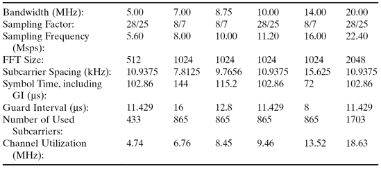
A sampling factor is applied to adjust the channel utilization, depending on the precise channel bandwidth (for instance, 8.75 MHz versus 10 MHz), without changing the number of subcarriers. This keeps the slot scheduling, subcarrier permutation, and bit interleaving parameters constant, regardless minor differences in channel width.
14.3.4.3 WiMAX at 70 Mbit/s.
Marketing material for WiMAX often sports a data rate of 70 Mbit/s. A discussion of this number will provide some valuable insights.
To start, the stated rate is based on a 20-MHz channel, which implies a 2048-pt FFT.
After resampling at ![]() , and
insertion of a
, and
insertion of a ![]() -guard interval, the symbol time
becomes 129 µs. Out of the 2048 subcarriers, the standard uses 1536 for data,
leaving the rest unused as guard bands.
-guard interval, the symbol time
becomes 129 µs. Out of the 2048 subcarriers, the standard uses 1536 for data,
leaving the rest unused as guard bands.
The pilot overhead varies, depending on the mode of operation. At the low end, it is about 11% to 15% for DL and UL, and at the high end it can reach to 33% for UL.
Then there is a small amount of overhead due to the preamble, some regularly scheduled MAC messages, and ranging. There are also minimal RTG and TTG silence gaps between the UL and DL subframes. All this overhead can be neglected for simplicity.
The highest data rate is provided by 64-QAM rate modulation with rate
![]() coding. At this rate, each
symbol and each data carrier contains 5 bits of uncoded data.
coding. At this rate, each
symbol and each data carrier contains 5 bits of uncoded data.
Putting all this together, the total data rate over a 20-MHz channel
then becomes 1536 subcarriers * 6bits * 1/(100 µs*(1 + ![]() )) *
)) *![]() * 89% = 69.3503 (Mbps), or about 70 Mbit/s.
* 89% = 69.3503 (Mbps), or about 70 Mbit/s.
This number scales proportionately with the channel bandwidth. Thus a 10-MHz channel can yield 35 Mbit/s and a 5-MHz channel can yield 17.5 Mbit/s.
The bandwidth efficiency is thus 3.5 bits per second per hertz of channel bandwidth.
It should be noted that this is an approximation of the maximum supported rate by the modulation scheme. Under normal deployment conditions, only a fraction of the stations can be addressed at the highest modulation and coding rate. As the distance between subscriber and BS increases, the connection rate will drop since the scheduler will switch to more robust modulation schemes (at fewer data bits per subcrarrier) to keep the BER below limits.
As an aside, the theoretical data rate or bandwidth efficiency could be further increased by the use of even higher modulation rates, such as 256QAM. One could also increase the symbol rate or narrow the subcarrier spacing with a higher-order FFT. But given the mobile channel conditions, these would add complexity that would be rarely, if ever, used,. They are also quite challenging to implement.
The standard offers other schemes at the PHY level that can be used to increase data rate in real deployments. MIMO and subchannel utilization schemes are available to increase spectral efficiency and throughput depending on channel conditions.
14.3.5 Radio Resource Management and Subchannel Utilization
Radio Resource Management (RRM) in cellular networks involves the optimization of transmit power, user scheduling, and the occupation of frequency channels to maximize the cellular throughput per hertz of bandwidth of the radio spectrum. RRM also involves providing coverage over the entire geographic target area, maximizing cell throughput, and meeting broadband service plan commitments. Other factors that come into play are minimizing the overhead from handover and idle stations, consideration of the link budget in the farthest parts of the cell, and planning for terrain and urban obstructions.
14.3.5.1 Adaptive Modulation and Coding (AMC).
The term “Adaptive Modulation and Coding” (AMC) refers to the adaptation of the modulation and the coding rate, depending on the channel conditions. The specific term AMC was first introduced in 3G cellular technology, under the revision 1xEVDO-Rev 0. The High-Speed Downlink Packet Access (HSDPA) extension of WCDMA includes the capability to adjust the modulation rate from QPSK to 8PSK and 16QAM as the signal-to-noise and interference ratio of the link improves.
In earlier versions of cellular communications, the modulation and the
rate were fixed. Typically, it was BPSK and/or QPSK with rate ½ coding. With advent
of higher-speed processing and demand for higher spectral efficiencies, the use of
higher-order modulations and coding rates became necessary. EDGE (enhanced GSM)
provisions Gaussian Minimum Shift Keying (GMSK) based on 8-PSK. HSDPA (2005) also
provisions AMC with QPSK and 16QAM modulation combined with code rates of ¼, ½, ![]() , and ¾.
, and ¾.
IEEE 802.16e includes AMC, and it is also used in other wireless technologies. In 802.11 (WiFi), modulation and coding are adjusted as part of the Modulation and Coding Scheme (MCS) algorithms.
AMC operates in supplement to power control. The intent of power control is twofold. It minimizes the transmit power in order to minimize the interference within the cell and from cell to cell. In addition, power control reduces the power draw from a mobile’s battery. An MS near a BS will simply be controlled to transmit at a lower power level.
AMC is then applied on top of power control, to maximize the data rate at the desired transmit power level. Moreover, AMC provides a fine granularity of packet sizes within a fixed frame, thus adding the ability to minimize unused parts of the frame (the stuff bits).
To further improve the robustness for stations at a far distance and to further improve spectral efficiencies for stations near their serving BS, AMC is supplemented by MIMO. Depending on the channel conditions for each MS served, the BS can schedule these stations in groups, addressing some with MIMO modes tailored for robustness [e.g., space time codes (STC)] and others for modes that increase efficiency [e.g., spatial multiplexing (SM)]. This is called adaptive MIMO systems (AMS).
14.3.5.2 CINR and RSSI Channel Measurement and Feedback.
For bands below 11 GHz the BS has the option to request channel measurements by the MS. This includes two metrics for the quality of the RF air channel: carrier to interference and noise ratio (CINR) and the receive signal strength indicator (RSSI). The BS uses these to rapidly adapt and optimize the schedules, to map subscribers to subchannels that are best for their reception, and to avoid interference with other cells.
It is also used to minimize interference to and from other IEEE systems (e.g., WiFi) or non-IEEE systems (e.g., radar) in the geographical vicinity. This is particularly addressed in the 802.16h amendment for coexistence.
For MIMO operation (see below) there are additional feedback mechanisms, to allow the transmitter to calculate its MIMO coefficients based on the channel. This includes a channel quality indicator (CQI) and other feedback by the MS, such as a choice of preferred number of BS-activated transmit antennae and a preferred burst profile. Channel coherence time can also be fed back, which matters if the BS is calculating MIMO pre-coding coefficients for a later transmission to the same MS.
14.3.5.3 Subchannel Utilization Modes.
Frequency planning is another aspect of RRM. The standard allows for frequency planning at a subchannel level. There are several modes that differ in how subcarriers are allotted to share the channel among users of neighboring cells.
DL FUSC.
Downlink full utilization of subchannels (FUSC) involves transmissions using the full breadth of the channel. This is applied where there is no inter-cell or inter-sector interference and where rapidly changing channel conditions make it impractical to optimize the burst profile for any specific MS.
Pilot carriers occur one out of every seven subcarriers, and they are spread evenly across the channel. Data carriers are assigned to the remaining subcarriers, whereby each connection uses a sparse subset of subcarriers from across the entire channel. The MS receiver estimates and tracks the channel based on all pilots across the entire channel, and it applies interpolation to equalize the specific data subcarriers assigned only to it.
A pseudo-randomization scheme permutes the subcarrier assignments from symbol to symbol, which improves the gains from frequency diversity.
DL PUSC.
Partial utilization of subchannels (PUSC) is applied in the DL
to provide fractional frequency reuse (FFR) with neighbor cells. In PUSC, a BS
schedules only part of the channel (often ![]() ) for receivers near the cell edge.
Such a PUSC segment is formed by logically grouping a
selection of subcarriers.
) for receivers near the cell edge.
Such a PUSC segment is formed by logically grouping a
selection of subcarriers.
Segments do not section the channel into physical sub-bands. Instead they pseudo-randomly map logical subcarriers to a subset of physical subcarriers across the entire channel. Interference is avoided because neighboring cells or sectors are assigned different segments, and thus the subcarriers spectrally interleave without colliding.
Pilots are evenly distributed within subchannels, and data subcarriers are permuted evenly across the subchannel.
UL PUSC.
In the uplink, each transmission from an MS requires its own pilots, since each channel from a MS to the BS is different. The BS cannot use pilots from one MS to equalize the data subcarriers from another.
Therefore pilot and data subcarriers are combined in a time–frequency tile, and tiles are permuted across the designated PUSC subchannel. The pilots reside on the corner of the tile, and the BS uses them to equalize the transmission from a given MS. There are eight data and four pilot subcarriers that form a tile of three symbols by four subcarriers.
There has been no need for a full-channel UL FUSC, since one MS would rarely ever need to occupy the entire channel. Therefore, tiles are only assigned to a segment.
Optional UL PUSC.
There is an option to reduce overhead from pilots where channel conditions permit. PUSC can also operate with eight data and one pilot subcarrier to form a tile of three symbols by three subcarriers. The pilot is in the center of the tile.
TUSC 1 & 2.
Tiled utilization of subchannels (TUSC) is the same as PUSC but for the DL. This allows a TDD BS to schedule UL and DL for a specific MS using the same physical part of the channel for both directions. The BS can then infer the transmit channel from the received signal to calculate AAS pre-coding coefficients. The two TUSC modes respectively correspond to a 3 × 4 and a 3 × 3 tile for reduced overhead.
Band AMC.
In band adaptive modulation and coding (band AMC), the BS scheduler has access to adjacent physical subcarriers of the channel. This is also called the adjacent subcarrier mode. It operates with eight data and one pilot subcarrier grouped into a bin, which is mapped to an FFT sub-band within the channel.
The BS can operate at a higher burst rate for a selected MS by specifically scheduling it in portions (sub-bands) of the channel where the SNR is high. If the subscriber is not moving, Band AMC can provide higher throughput than the frequency diverse FUSC or PUSC modes.
In FUSC and PUSC, subcarriers are assigned pseudo-randomly and loaded with AMC based on the average SNR across the assigned subcarriers. The maximum achievable rate to an MS with the best SNR is lower than with band AMC, but the BS does not need to rapidly update the burst profile as the channel fluctuates during mobility.
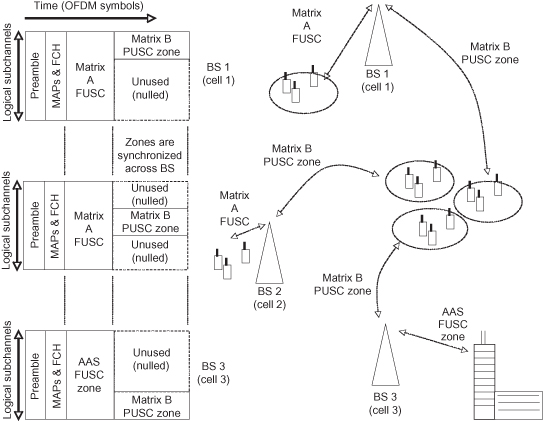
14.3.5.4 Zones.
To combine different subchannel utilization modes in a single DL or UL subframe, the subframe is split into zones. The operator synchronizes the zone boundaries in all its BSs across its network, in order for FUSC and PUSC to be effective in interference mitigation.
Zones are also used to schedule MSs with similar requirements for noise and interference robustness together in time. Thus an MS scheduled for a particular zone does not have to attempt to track pilots over the entire frame, but rather can wait to detect and adapt until its designated zone (with suitable SNR) is received.
Although an MS receiver only needs to process the pilots in symbols for which it needs to demodulate data subcarriers, it is advantageous to start estimation of the channel earlier in the frame, even though data are scheduled for other stations. However, if interference levels are significant, the MS can wait until the start of its zone before processing the pilots.
To this end, zone switches are broadcast by the BS.
An example of zones and subchannelization is provided in Figure 14.7.
Figure 14.7. Example of zones and subchannelization.
14.3.5.5 Fractional Frequency Reuse (FFR).
Frequency reuse refers to the reuse of a channel or a fraction of it so that it can be shared with a neighboring cell.
Operators with access to three channels use Frequency Reuse 3 cell planning to manage interference. In these cases the interference between cells is reduced at the expense of small inefficiencies in terms of channel spectrum utilization. MSs in neighboring cells operate at different RF frequencies, and so their transmissions do not interfere. In parts of the BS coverage area, such as at the cell edge, this is highly needed, but in other parts, such as close to the BS, this leaves much of the spectrum unused. The net effect is nevertheless a gain in spectral efficiency (bits/s/Hz per BS).
Sectorization is based on the same principles of frequency reuse, and it offers more options to reduce interference and improve efficiency. It comes at the cost of more equipment at the base station, because each sector requires separate high-power RF modules and antennae.
The standard offers PUSC for fractional frequency reuse (FFR). Figure 14.8 shows two different configurations of a cellular plan. The object is to minimize inter-cell and inter-sector interference caused by MS and BS transmissions in neighboring cells and sectors.
Figure 14.8. Frequency reuse 3 (left) and single-channel FRF (right).
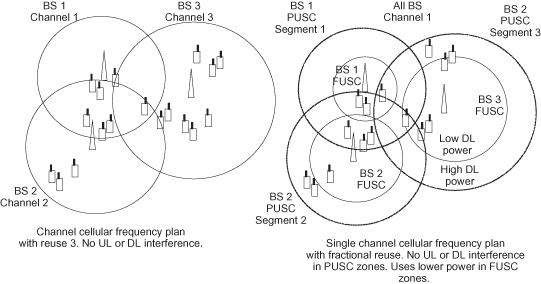
At cell edges the interference level from a neighbor BS is often as strong as the intended signal from the serving BS. The standard provides very robust repetition codes for this scenario, but the resulting frame inefficiency is of course undesirable.
The BS schedules cell-edge MSs in a PUSC zone, which isolates them from interference. This alleviates the frame inefficiency at the expense of some spectral inefficiency in the cell edge.
The inefficiency does not apply to the entire cell. The BS schedules nearby MSs, which do not experience the interference, in a FUSC zone. The operator synchronizes the FUSC zones among BSs, so that neighbor BSs can do the same to their nearby MSs. Thus the spectrum is fully reused where interference allows.
To further combat the effects of FUSC interference at the receiver’s decoder, interfering stations are assigned a different permutation base. The distinct bases ensure that subcarrier “collisions” are rare and random so that the interference is not persistently high for any individual MS.
14.3.6 Error Control
Error control involves two aspects. Forward Error Correction (FEC) is an efficient method to reduce the error rate (the bit error rate and resultant loss of a burst) over-the-air using DSP. Automatic Repeat Request (ARQ) is a method to recover lost bursts. FEC minimizes the need for ARQ, and ARQ minimizes the exposure of errors to the network.
14.3.6.1 Forward Error Correction (FEC) and Interleaving.
The burst profile defines the
precise modulation and coding combination of a scheduled burst between stations. It
covers the choice of modulation (QPSK, 16QAM, or 64QAM), the choice of the FEC
scheme (CC, CTC, LDPC, ZCC, BTC), and the coding rate FEC parameter (rate ½, ![]() , ¾,
, ¾, ![]() ).
).
The Convolutional Code (CC) produces an output bit sequence out of an input sequence by passing it through a binary feedback shift register. This operation convolves the input sequence with a reference encoding sequence called the code polynomial. The length (also called “depth”) of the shift register corresponds to the order of the polynomial, and it is called the constraint length. For CC it is K = 7.
The CC codes are based on two polynomials, and for each input bit two output bits are produced. The base rate (or native rate) is thus ½, and for a burst at rate ½, both coded bits are transmitted for each data bit.
A code rate of ![]() can be attained with the same code.
In a process called puncturing, the transmitter
alternates by sending both coded bits, then just one (dropping the other), then both
again, and so on. Puncturing is also used to attain rate ¾.
can be attained with the same code.
In a process called puncturing, the transmitter
alternates by sending both coded bits, then just one (dropping the other), then both
again, and so on. Puncturing is also used to attain rate ¾.
A base code has more redundancy than its punctured code, but it performs
better for noisy receptions. 802.16e supports code rates ½, ![]() , and ¾.
, and ¾.
There are two variants to the CC, one with tail biting and one with flush bits. Flush bits add some overhead but provide for a simpler decoder. This is also called a Zero Terminating Convolutional Code, or ZCC.
The standard also provides for a Convolutional Turbo Code (CTC) and a
Block Turbo Code (BTC). The CTC is a duo-binary code which means it has two encoding
polynomials. The output of the first shift register is interleaved and convolved
with a second polynomial. The native rate is ![]() , and puncturing provides the rates ½,
, and puncturing provides the rates ½,
![]() , ¾, and
, ¾, and ![]() .
.
The decoder for CTC is more complex than for CC. It is iterative, and the decoding time depends on the amount of noise in the signal.
The OFDM mode of the standard also includes a Reed–Solomon FEC with codeword length 255 containing 16 check bytes, but this is not required by any of the profiles.
The coding gain would rapidly decline if the decoder were presented with strings of adjacent bit errors rather than a same amount of isolated bit errors. This is a drawback of the type of FEC used, but it is easily avoided. To remedy this, an interleaving step after encoding at the transmitter enables the placement of a de-interleaver before decoding at the receiver.
A de-interleaver merely re-orders coded bits, and it does not directly improve the SNR of the received constellations. Rather, it reduces the probability that errored code bits occur in clusters at the input of the FEC decoder. This improves the probability of error correction, which in turn reduces the BER at the output of the FEC.
In OFDM(A), the adjacency of data bits must avoided by two steps.
In a first step, neighboring bits in the data stream are spread over non-neighboring subcarriers. Often a reduced SNR occurs in several neighboring subcarriers, for instance due to narrowband interference and/or fading (notches) in the channel. The de-interleaver will then cause the good and poor subcarriers to alternate at the decoder input.
The second step applies to higher-order constellations (16-QAM and 64-QAM). Random errors caused by Gaussian noise usually only affect the least significant bit of the constellation, because a small disturbance affects perhaps one bit of a multi-bit constellation point. The interleaver ensures that neighboring bits alternate as most and least significant bits, thus alternating their strength of protection against noise.
14.3.6.2 Automatic Repeat Request (ARQ) and Hybrid-ARQ (HARQ).
Automatic Repeat Request (ARQ) is a MAC level operation to attempt recovery from bit errors. It operates independently from the PHY. An MPDU is constructed with a number of blocks of data from one or more SDUs, and the transmitter can resend (automatically repeat) blocks of the MPDU, or even complete MPDUs, that have not been acknowledged by the receiver. ARQ is used to overcome brief air-link interruptions due to temporal fades. While FEC is designed to overcome random and sporadic bit errors within bursts, ARQ is designed to overcome significant frame losses.
The standard supports a few options for sending acknowledgments as a stand-alone management message or as a payload piggyback during a data response.
A 32-bit Cyclic Redundancy Check (CRC) is used to determine whether burst data have been received and decoded without error. The CRC is a data-dependent signature appended to the data unit. A CRC can confirm with sufficiently high probability (but theoretically not with absolute certainty) that the decoded data is error-free.
Hybrid ARQ (HARQ) is an alternative offered by the PHY by tightly coupling retransmissions with the FEC. The MPDU is processed by the PHY, where it is FEC-encoded to produce up to four coded and punctured versions of the same data. In a first transmission of the data, the PHY only transmits one version. If the CRC passes at the decoder, then no further versions are needed, and a new MPDU can be transmitted. However, if the CRC fails, then a different version of the data is sent. This is called a stop-and-wait protocol, because the receiver waits for the repeat data before proceeding with the rest of the data.
To reduce latency, the transmitter sends a further ARQ block of data even before it has received an acknowledgment for a previous block. Thus, acknowledgments are lagged and for most of the time, while there are no block errors, latency is shortened.
For rate ¾ Incremental Redundancy HARQ (IR-HARQ), the data are coded at rate ½ and then punctured to ¾. The puncturing sequence is altered for the retransmission. By keeping the retransmission rate at ¾, scheduling is simplified since both transmissions require the exact same number of coded bits. A simple receiver can opt to discard the first transmission and to decode the retransmission at rate ¾ without needing the first transmission. A more complex receiver can merge the two sequences to yield a code that is slightly stronger than rate ½.
Another repetition scheme by the PHY is Chase HARQ. In this case, the precise same encoder output bits (with same puncturing) are simply retransmitted. This allows the receiver to sum the received signals before decoding, which averages out some of the noise, yielding a 3-dB SNR improvement.
Repetition codes operate in the same way, except that with Chase Combining the repetition is on-demand, in the event of a CRC failure. In order to get a precise duplicate of the previous transmission, the burst profile and data must be the same. This is different from Hybrid ARQ, where the coded sequence is different. It is also different from ARQ, where the same Data Unit is retransmitted by the MAC, but where the PHY may apply a different modulation and coding rate to it.
14.3.7 PHY MIMO Techniques
Multiple-Input Multiple-Output (MIMO) techniques are used in several cellular standards and other communication protocols to enhance the system capacity. MIMO techniques can improve a poor SNR at the receiver to enable higher modulation and coding rates. And if the SNR is already high, MIMO can be used to further raise the burst rate. Improvement of SNR is achieved with Space Time Codes (STC), its variants, and beam forming. Rates are increased with Spatial Multiplexing.
MIMO techniques can be split into open-loop and closed-loop techniques. An open-loop transmitter operates without knowledge of the RF channel, and a closed-loop transmitter operates with channel knowledge.
When the transmit channel is inferred from the receive signal, feedback is said to be implicit. In TDD systems the MIMO transmitter can infer its channel from the channel conditions during previously received bursts, since both directions use the same RF channel.
In contrast, an FDD system employs different channels for UL and DL. The MS must send a designated message to the BS, containing information about the DL channel. When channel information is messaged back from the target receiver to the MIMO transmitter, feedback is said to be explicit.
MIMO systems gain over single-antenna systems through array gain and diversity gain.
Array gain is the improvement of the signal strength attributed to the reception of a larger proportion of the radiated signal power. Quite simply put, an array of two antennae together in one receiver captures twice the amount of RF power compared to a single antenna. Array gain can equivalently be attributed to the transmitter, when two transmitters of an array radiate twice the RF power of one transmitter. The challenge in realizing array gain arises when processing the array signals. Combined signals must be synchronized and equalized in order to sum constructively.
Diversity gain is the improvement of a decoded signal due to the reception or transmission of diverse versions of a same signal. Temporal diversity occurs when the two versions are delivered at distinct instances in time. Frequency diversity occurs when the two are delivered in distinct subcarriers.
In MIMO, spatial diversity occurs when the versions are received and/or transmitted by distinct multiple antennae. Separation at the MS is usually half the wavelength. At the BS it is often several times the wavelength.
14.3.7.1 Antennae and Antenna Arrays.
The antenna beam width quantifies the directionality of an antenna or antenna array. It is a measure related to the antennae radiation pattern. The pattern usually features a dominant beam, and the width of the beam is called the spatial angle.
The antenna array is designed such that its pattern matches the coverage requirements for the base station. In some cases the pattern is omnidirectional, and the entire cell around the base station is serviced as one sector. This would typically be the case for smaller in-building pico cells or femto cells that service under 100 calls. In macro BSs, where the radio head resides on top of an outside tower, the antenna array is more complex, often comprising of four antennae per sector, with three sectors per cell. The beam of a sector covers a 120-degree division. The directionality of the antenna array offers further range within the sector, along with less cell-to-cell interference.
14.3.7.2 Spatial Multiplexing and Virtual (Collaborative) MIMO.
At frequencies below 11 GHz, in particular at those envisioned for 16e, namely 700 MHz to 5.8 GHz, there is plenty of spatial diversity to allow the use of MIMO techniques.
Transmit spatial diversity refers to the use of multiple antennae for transmission, and receive diversity refers to the use multiple antennae for reception. Usually the same antennae used for transmission are also used for reception. To reduce the cost of an MS, transmission drives one antenna, but reception uses two. Such an MS would be called a 1 × 2 MIMO device.
Spatial Mutliplexing (SM) involves the transmission of multiple streams of data simultaneously, in the same subcarriers and at the same time. Each stream is transmitted by a separate antenna. To decode these streams the receiver must have an antenna count at least equal to the number of streams. For instance, a 1 × 2 MS can receive two spatially multiplexed signals. Each antenna requires its own RF and DSP processing, plus additional MIMO decoding across both received signals to separate the multiple streams.
In Collaborative MIMO, pairs of MS are scheduled so that both transmit simultaneously and the two signals blend in a SM fashion. This is also called Space Division Multiple Access (SDMA) or Virtual MIMO. Thus the cell throughput can theoretically be doubled during the UL, using MS that have just a single antenna. This is illustrated in Figure 14.9. The requirement to operate pairs of stations poses a challenge on the scheduling algorithms in the BS. Both stations must be capable of Virtual MIMO operation, and they must both be positioned to deliver signals to the BS with close SNR and close reception levels.
Figure 14.9. Collaborative MIMO and SDMA.
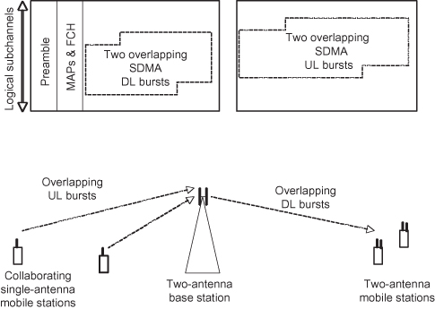
On the DL, two MSs can be scheduled to receive overlapping signals. Each MS requires two antennae to separate the SDMA signal intended for it and discard the other.
14.3.7.3 Adaptive Antenna Systems (AAS), Smart Antennae, and Beam Steering.
Adaptive Antenna Systems (AAS) refer to the adaptation of the transmit signal by precoding the signals from each of several antennae. Precoding consists of optimal phase and amplitude adjustments on a per-subcarrier basis, so that the sum of the multiple signals coherently add-up at the receiver. Of course, the adjustment depends on the channel from transmitter to receiver. Feedback is used to determine the channel and make the adjustments, and the transmitter is thus said to be “smart” about the channel.
Precoding at the transmitter is often also called beam forming or beam steering. This name finds its origins in the directed radiation pattern that forms from the antenna array. Such a pattern appears when there is line-of-sight (LOS) radiation, void of any reflections on the path to the receiver. This is typical in fixed outdoor-to-outdoor type transmissions. In outdoor-to-indoor applications, however, there are substantial reflections and as a result the channel phase and amplitude depend greatly on the subcarrier. Thus there can be a completely different beam per subcarrier, but these non-line-of-sight (NLOS) conditions do not necessarily limit the benefits.
Precoding can also be used for null steering rather than beam steering so that the sum of the multiple signals coherently vanish at a receiver. The object of steering a null is to minimize the energy to a cluster of MSs that are serviced by a neighboring BS. The algorithm for calculating the antenna steering coefficients is different, and it results in a purposeful null rather than a purposeful beam.
Similar adaptation of the array can also be applied during reception. This is sometimes called receive beam forming. It does not require standardization, because it is a receive-only process. Phase and amplitude coefficients are applied per subcarrier, so that the sum of the multiple received signals coherently add-up at the decoder. Maximum Ratio Combining (MRC) is an example of such a technique. The coefficients can also be calculated so that the signal from a nearby interferer vanishes at the decoder input.
Special zones and superframe structures accommodate AAS. An OFDMA superframe is a set of normal frames, of which some are regular frames and some are AAS-only frames. Under this kind of superframing, a great number of MSs can be efficiently served with AAS. The MSs simply do not even attempt to receive the preamble or decode any channel descriptors and maps in frames that are not designated to them. Thus the BS can beam-form select MSs in select frames without losing connections to other MSs.
An AAS-Zone provides a similar mechanism, yet at a smaller scale. This zone has its own preamble, channel descriptors, and maps for DL and UL scheduling. The entire zone is beam-formed to select MS.
By using a zone or superframe, distant stations can decode preambles and scheduling parameters, which extends the reach of the BS. Without such a zone or superframe, AAS would only be able to boost the rates of stations that are already within reach.
14.3.7.4 MIMO with Two Transmit Antennae.
The standard supports various MIMO techniques for transmitters equipped with two antennae.
2 × 1 Space–Time Coding (STC).
STC is also known in the standard as Matrix A, and it provides spatial transmit diversity and array gain. The code spreads data over two antennae, and its salient feature is that the receiver requires only a single receive antenna. It operates independently on each subcarrier. Encoded constellation points (e.g., a two-bit pair in a QPSK symbol) are grabbed pairwise. One symbol point is transmitted on one antenna, the other on the second antenna. In a subsequent OFDM symbol the same point is transmitted, but the first point is conjugated, and transmitted on the second antenna, and the other is negated, conjugated, and transmitted on the first antenna. It offers the highest spatial diversity for the given antenna configuration, but no rate increase. It is therefore a rate 1 code.
This code is also referred to as an Alamouti code, named after its inventor.
STC improves the link budget by transmitting spatially diverse signals to the receiver. The implementation cost resides primarily at the transmitter, since the receiver requires only one antenna and RF circuit. This technique is classified as an open-loop MIMO technique because the transmitter requires no knowledge of the RF channel. It is quite suitable for mobile conditions where channel information is inconsistent from frame to frame. Moreover, it can be used for broadcasting to stations across completely different channels. STC is applied to all subcarriers in the symbol, and STC bursts are joined in a designated zone with special pilots.
Frequency Hopping Diversity Coding (FHDC).
FHDC is a Space Frequency Code (SFC) that requires OFDM and is equivalent to STC. The conjugate complex retransmission occurs in a different subchannel, rather than in a different symbol. SFC provides the same spatial gains as STC, but offers additional frequency diversity when the channel is heavily affected by multipath reflections.
Precoding.
The standard covers several options for antenna selection and beam forming with various levels of complexity. An MS can advise its serving BS which antenna to best use for the next burst, based on signal evaluations from previous bursts. An MS can calculate precoding coefficients for the BS and can communicate them to the BS for a following transmission. Alternatively, the MS communicates channel information back to the BS, and the BS performs the calculation of the precoding coefficients itself.
Precoding techniques provide transmit array gain and greater diversity gain compared to STC. They work well with stationary channels.
Cyclic Delay Diversity (CDD).
CDD operates at the transmitter and generally requires no special processing at the receiver. An OFDM symbol is transmitted from one antenna, and a replica of it is transmitted from the second antenna. Before transmission, the waveform of the replica is cyclically rotated in time. This avoids unintentional constructive signal summation at the output of the transmitter.
CDD provides mainly array gain with a small amount of diversity gain. The cyclic rotation of the time domain waveform can equivalently be applied as a frequency domain operation at the input of the FFT. CDD changes the end-to-end channel transfer function as perceived by the receiver, and therefore CDD must be applied to the pilots (UL and DL) as well as to the preamble (DL). The delay must be restricted to a small amount, in order to maintain the integrity of the receiver’s synchronization algorithms.
Spatial Multiplexing (SM).
SM is also known in the standard as Matrix B, and it is used to boost the data rate where SNR permits. This is a rate 2 code, and it requires at least two transmit and receive antennae. Each antenna simultaneously transmits constellation points pertaining to different data. In Horizontal Encoding, the data are provided by two distinct FEC encoders, each with independent coding and modulation rates. The data streams can be scheduled independently and the MCS can be optimized separately. In a simpler version called Vertical Encoding, the output of a single FEC encoder is multiplexed over two antennae. The benefit is that SNR differences between the streams are averaged out at the decoder, which provides simpler scheduling.
SM increases the data rate by a factor proportionate to the number of antennae, and in effect it multiplies the spectral efficiency. SM decoding introduces self-interference, which somewhat degrades the effective Signal to Interference and Noise Ratio (SINR) at the FEC decoder.
Receive Diversity.
To further increase the diversity gains from these techniques, the receiver can optionally be equipped with additional antennae. This provides further array gain as well as diversity gain. Common receiver-only techniques are based on antenna selection (Switched Diversity), RF signal combining [Equal Gain Combining (EGC)], and DSP-signal combining [Maximum Ratio Combining (MRC)]. These techniques are at the discretion of the device manufacturer and do not require standardization.
Figure 14.10 illustrates MIMO processing on a subcarrier basis. This applies to all OFDM spatial diversity techniques, such as spatial multiplexing, beam forming, and space time/frequency codes. Spatial multiplexing requires multiple receive antennae to decode the multiple streams of data. Space time/frequency codes require MIMO decoding to realize the transmit diversity gain. Beam forming requires little extra at the receiver, but this comes at the cost of coefficient calculations at the transmitter.
Figure 14.10. (a) Spatial Multiplexing, (b) Space Time/frequency Codes, and (c) Beam Forming.
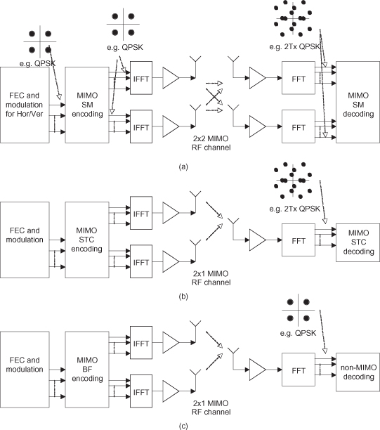
14.3.7.5 MIMO with Three or Four Transmit Antennae.
The standard also defines techniques for three and four transmit antennae based on the MIMO techniques for two transmit antennae. As with two antenna techniques, separate zones can be configured for different MIMO techniques in order to dramatically improve reach and spectral efficiency.
STC with Four Antennae, Using “Matrix A”.
This scheme place four antennae in two groups, and for every symbol it alternates the STC between the two groups. It is a rate 1 code and requires a single-antenna receiver with a STC decoder.
STC with Four Antennae, Using “Matrix B”.
Two streams of data are supplied to two parallel and independent STC encoders, providing signals for four antennae. It combines 2× STC with 2× spatial multiplexing. This is a rate two code, and it requires a receiver with two antennae, along with a combined SM/STC decoder.
STC with Four Antennae, Using “Matrix C”.
This scheme is 4× SM, without STC. It requires a four antenna receiver. This option is used for fixed stations.
STC with Two Antennae, Using Directivity for Four Antennae.
One STC supplies signals for two antennae. In addition, a duplicate of each of these signals is precoded using MIMO feedback coefficients recommended by the MS. It is a rate 1 code with a total of four signals transmitted simultaneously. The receiver requires a single antenna and an STC decoder.
ACKNOWLEDGMENTS
Aryan Saèd would like to acknowledge the detailed chapter reviews provided by Kenneth Stanwood, Darcy Poulin, and Peter Stewart. Their experience from direct participation in the IEEE 802 meetings and the WiMAX Forum has been invaluable for many of the insights and backgrounds provided in the text.
BIBLIOGRAPHY
J. G. Andrews, A. Ghosh, and R. Muhamed, Fundamentals of WiMAX—Understanding Broadband Wireless Networking, Prentice-Hall, Upper Saddle River, NJ, 2007.
T. Cooklev, Wireless Communication Standards—A study of 802.11, 802.15 and 802.16, IEEE Press, New York, 2004.
Draft Amendment to IEEE Standard for Local and Metropolitan Area Networks, Part 16: Air Interface for Fixed and Mobile Broadband Wireless Access Systems Improved Coexistence, Mechanisms for License-Exempt Operation, P802.16h/D8, 2008-11-22.
Draft Amendment to IEEE Standard for Local and Metropolitan Area Networks Part 16: Air Interface for Fixed and Mobile Broadband Wireless Access Systems, Multihop Relay Specification, P802.16j/D9, 2009-02-04.
C. Erklund, R. B. Marks, S. Ponnuswamy, K. L. Stanwood, and N. J. M. Van Waes, WirelessMAN—Inside the IEEE 802.16 Standard for Wireless Metropolitan Networks, IEEE Press, New York, 2006.
V. Genc, S. Murphy, Y. Yu, and J. Murphy, IEEE802.16j relay-based wireless access networks: An overview, IEEE Wireless Communi., Vol. 15, No. 5, pp. 56–63, October 2008.
Intel Technol. J., Vol. 8, No. 3, pp. 173–258, August 2004.
Mobile WiMAX—Part I: A Technical Overview and Performance Evaluation, WiMAX Forum, 2006.
Mobile WiMAX—Part II: A Comparative Analysis, WiMAX Forum, 2006.
A. Molisch, Wireless Communications, John Wiley & Sons, Hoboken, NJ, 2005.
R. van Nee and R. Prasad, OFDM for Wireless Multimedia Communications, Artech House, Norwood, MA, 2000.
S. W. Peters and R. W. Heath Jr., The future of WiMAX: Multihop relaying with IEEE802.16j, IEEE Communi. Maga, Vol. 47, No. 1, pp. 104–111, January 2009.
Standard for Local and Metropolitan Area Networks, Part 16: Air Interface for Broadband Wireless Access Systems, 802.16-2009, 29 May 2009.
D. Sweeney, WiMAX Operator’s Manual—Building 802.16 Wireless Networks, Apress 2006.
J. Sydor, Messaging and Spectrum Sharing Between Ad-Hoc Cognitive Radio Networks, ISCAS, Island of Kos, Greece, 2006.
WiMAX Forum Mobile Certification Profile Release 1.0 Approved Specification (Revision 1.1.0), 2008-12.
WiMAX Forum Mobile Certification Profile, Release 1.5 Approved Specification (Revision 1.0.0), 2008-12.
WiMAX Forum Mobile Protocol Implementation Conformance Statement (PICS) Proforma, Release 1.0 Approved Specification(Revision 1.5.0), 2008-09.
WiMAX Forum Mobile Radio Conformance Tests (MRCT) Release 1.0 Approved Specification (Revision 2.2.1), 2008-10.