17
RESILIENT BURST RING: A NOVEL TECHNOLOGY FOR NEXT-GENERATION METROPOLITAN AREA NETWORKS
17.1 INTRODUCTION
In existence for over a decade now, the metropolitan area network (MAN) has traditionally been designed for voice transmission based on the time division multiplexing (TDM) technology. At that time, voice traffic was significantly more important than data traffic. As a result, synchronous optical network/synchronous digital hierarchy (SONET/SDH) became the dominant standard on these networks. Those technologies have been able to meet the initial requirements of MANs quite adequately, and today most of them are based on SONET/SDH technology.
With the explosion in the demand for bandwidth for data transmission, it became quite clear that SONET/SDH networks needed to be reengineered to handle data traffic in a more efficient way. The new MAN technology should connect all the various access networks and provide everything from real-time services to traditional data-transfer services. It should also provide Quality of Service (QoS) and handle any kind of traffic, from constant bit-rate traffic to packet- or cell-based traffic. While such a multiservice network would minimize overall operating costs, the existing SONET/SDH infrastructure is unfortunately unable to meet these requirements. The worst-case scenario is that the operators must maintain their legacy networks for legacy services while the new services need overlapping network infrastructure.
In recent years, SONET/SDH-based transport networks have come to be considered as too inflexible, inefficient, and overly complex for the purposes of data communication. As the importance of data communication has increased, research has begun for the replacement for the traditional SONET/SDH networks. That led to the emergence of the next-generation SONET/SDH [1, 2] and the resilient packet ring (RPR) [3, 4], and it also led to an increasing number of networks based on the dense wavelength division multiplexing (DWDM), such as optical burst switching (OBS) [5, 6], optical burst transport (OBT) [7, 8], and so on.
17.1.1 Next-Generation SONET/SDH Network
Next-generation SONET/SDH network offers a major step in combining new multiservice metro-access/transport equipment into legacy traditional SONET/SDH networks. It enables new types of services with more efficient network usage to be easily implemented by utilizing existing infrastructure.
Next-generation SONET/SDH extends the utility of the existing SONET/SDH network by leveraging existing layer 1 networking and including technologies such as generic framing procedure (GFP), virtual concatenation (VCAT), and the link capacity adjustment scheme (LCAS), and it integrates the customer interface into the network elements. GFP is defined in ITU-T G.7041 and ANSI T1-105.02 standards. It is an all-purpose protocol for an encapsulating packet over SONET (POS), ATM, and other Layer 2 traffic on the SONET/SDH networks. VCAT technology is the solution to the inefficiencies inherent in fixed payloads and contiguous concatenation. LCAS, a VCAT control mechanism, allows for the addition or reduction in the payload capacity of a virtual concatenation group (VCG) to meet the bandwidth needs of the application. Moreover, LCAS also offers other benefits, such as dynamically replacing failed member links within a VCG without removing the entire VCG. Unidirectional control of a VCG allows for asymmetric bandwidth, allows interworking of an LCAS transmitter with a non-LCAS receiver and vice versa, and aids in the creation of customer-based, on-demand services, and so on.
The next-generation SONET/SDH networks are core and metro networks with edge transport and traffic aggregation equipment that represents a significant generational improvement in functionality, size, and capacity compared to traditional SONET/SDH. New equipment is being designed that retains the traditional SONET/SDH functionality but in a package size five to ten times smaller. These systems are also inherently designed for multi-wavelength applications. Their SONET/SDH structure might also be “data aware,” enabling variable packet sizes to be carried and therefore making more efficient use of the available bandwidth.
Traditionally, the different services are provided through technology-specific transport pipes. However, the next-generation SONET/SDH enables the simultaneous transport of heterogeneous services over one wavelength, thereby saving network-building and maintenance costs. Moreover, using the next-generation SONET/SDH, which maps 8B/10B-coded data into 64B/65B-coded sequences, the required bandwidth is substantially decreased.
The most important merit of this technology is that the existing SDH network would not be replaced. Next-generation SONET/SDH has a transport mechanism that enables the concurrent existence of legacy and new services over the same network, without disturbing each other. However, the demerit of over-provisioning and LCAS latency will appear when it comes to supporting highly dynamic data traffic [9].
17.1.2 Resilient Packet Ring
Resilient packet ring, or RPR as it is commonly known, is the IEEE 802.17 standard designed for the optimized transport of data traffic over fiber rings. Its design is to provide the resilience found in SONET/SDH networks (50-ms protection) but instead of setting up circuit-oriented connections, providing a packet-based transmission. This is to increase the efficiency of Ethernet and IP services.
RPR works on a concept of dual counter-rotating rings called ringlets. These ringlets are set up by creating RPR stations at nodes where traffic is supposed to drop, per flow (a flow is the ingress and egress of data traffic). RPR uses MAC (Media Access Control protocol) messages to direct the traffic, which traverses both directions around the ringlet. The nodes also negotiate for bandwidth among themselves using fairness algorithms, avoiding congestion and failed spans. The avoidance of failed spans is accomplished by using one of two techniques known as “steering” and “wrapping.” In steering, if a node or span is broken, all nodes are notified of a topology change and they reroute their traffic. In wrapping, the traffic is looped back at the last node prior to the break and routed to the destination station.
All traffic on the ring is assigned a Class of Service (CoS), and the standard specifies three classes. Class A (or high) traffic is a pure CIR (committed information rate) and is designed to support applications requiring low latency and jitter, such as voice and video. Class B (or medium) traffic is a mix of both a CIR and an EIR (excess information rate, which is subject to fairness queuing). Class C (or low) is best effort traffic, utilizing whatever bandwidth is available. This is primarily used to support internet access traffic.
Another concept within RPR is what is known as “spatial reuse.” Because RPR “strips” the signal once it reaches the destination (unlike SONET/SDH, which consumes the bandwidth around the entire ring), it can reuse the free space to carry additional traffic. The RPR standard also supports the use of learning bridges (IEEE 802.1D) to further enhance efficiency in point to multipoint applications and VLAN tagging (IEEE 802.1Q, Virtual Local Area Network).
RPR is a new data transport technology designed to meet the requirements of a packet-base MAN. It is optimized for robust and efficient packet networking over a fiber ring topology and combines the best features of legacy SONET/SDH and Ethernet into one layer to maximize profitability while delivering carrier-grade service. This technology incorporates extensive performance monitoring, proactive network restoration, and flexible deployment capabilities. RPR answers for the future Quality of Service (QoS) requirements with three state QoS classes, and it provides less than 50 ms of protection with two different methods, steering and wrapping. The key features of RPR are differentiated services handling, fast resilience, and ring-wide bandwidth management. However, RPR implements a MAC protocol for access to the shared ring communication medium that has a client interface similar to that of the Ethernet. All the packets will be processed on Layer 2 at each node on the ring. Therefore, it will make the processing delay of RPR much longer than that of the SONET/SDH technology, which only needs the O/E/O conversation and some add/drop or OXC (optical cross connect) processing. Moreover, due to the process complexity, the max data rate that RPR can support now is only 10 Gbit/s. That is another restriction to RPR.
17.1.3 Optical Burst Switching
Optical burst switching (OBS) is a switching concept which lies between optical circuit switching and optical packet switching. It operates at the subwavelength level and is designed to better improve the utilization of wavelengths by rapid setup and teardown of the wavelength/lightpath for incoming bursts. In the OBS network, incoming traffic from clients at the edge of the network are aggregated at the ingress of the network according to a particular parameter [commonly destination, Type of Service (ToS), Class of Service (CoS), and Quality of Service (QoS)]. At the OBS edge router, different queues represent the various destinations or class of services. Based on the assembly/aggregation algorithm, packets are assembled into bursts by using either a time-based or threshold-based aggregation algorithm. In some implementations, aggregation is based on a hybrid of timer and threshold. From the aggregation of packets, a burst is created and this is the granularity that is handled in the OBS network.
In the OBS network, the burst header generated at the edge of the network is sent on a separate control channel which could be a designated out-of-band control wavelength. At each OBS node, the control channel is converted to the electrical domain for the electrical processing of the header information. The header information precedes the burst by a set amount known as an offset time, in order to give enough time for the switch resources to be made available prior to the arrival of the burst. Different reservation protocols have been proposed, and their efficacy has been studied and published in numerous research publications. Obviously, the signaling and reservation protocols depend on the network architecture, node capability, network topology, and level of network connectivity. The reservation process has implications on the performance of the OBS network due to the buffering requirements at the edge. The one-way signaling paradigm obviously introduces a higher level of blocking in the network because connections are not usually guaranteed prior to burst release. Again numerous proposals have sought to improve these issues.
An all-optical path for the data burst makes the transmission delay in the OBS network much shorter than that in the next-generation SONET/SDH and the RPR network. However, the efficiency of the OBS network can be reduced by resource contention of bursts directed to the same transmission links. Moreover, with the unidirectional resources reservation scheme, combining with the effect of buffering incurred by fiber delay lines (FDL) and the impact caused by the multiple paths transmission with the deflection routing scheme, the delay variation problem in the OBS network will be much worse than in the other two networks; in some cases, the packet will arrive in disorder, which will make the performance of the OBS network much worse, especially for the time-based services and applications. Finally, due to the signal impairment in the high-speed transmission systems and the lack of the ultra-high-speed large-scale optical switch matrix, OBS technologies do not seem to be practical in the near future.
17.1.4 Optical Burst Transport
As advances in tunable lasers and filters have made rapidly reconfigurable lightpaths a reality, to better support bursty and rapidly changing data traffic, a variation of OBS, which is called optical burst transport (OBT), was proposed by Kim et al. [7]. It can perform the no-blocking data transmissions and guarantee the QoS of the bursts.
The OBT is based on burst-mode transmission between senders and receivers on a WDM-enabled ring topology and does not require complex electronic processing. The burst transmission is made possible by swift reconfiguration of short-term lightpaths. The network architecture exhibits the following fundamental capabilities:
1. WDM-based technology with minimal electronic processing at the transit nodes.
2. Simple coupler-based wavelength add/drop. No MUX/DEMUX and active components on the rings.
3. Intelligent packet aggregation at OBT nodes.
4. Burst transmission via tunable lasers or tunable filters, or combinations of both.
5. Token-based wavelength access control.
In the OBT network, burst collisions can be easily avoided by using a token mechanism, which can also guarantee fairness among nodes. The traffic scheduler of a node manages the available capacity at multiple wavelengths for optimal transmission to destination nodes. In addition, control messages are exchanged between nodes, making the overall network reliable.
However, in the OBT network, the increase of the girth of the ring network or the number of stations on the ring will lead to the small value of the network efficiency and the long transmission latency [10]. In other words, to achieve a better data transmission performance, the scale of the OBT network needs to be limited.
In this chapter, we present a new efficient network technology for the next-generation 100-gigabit and terabit carrier-grade MAN, which is called resilient burst ring (RBR) [11]. It combines the concept of RPR with the burst-mode all-optical data transmission scheme to implement the ultra-high-speed data transmission with scalability and reliability. On the one hand, it inherits all the best features of the RPR networks and improves its data transmission rate to 100 Gbit/s or higher with the burst-mode all-optical data transmission scheme. On the other hand, it reduces the conflict probability of the data burst with the sample ring architecture and solves the packet loss problem with the two different buffering schemes. Moreover, it can provide different QoS classes to transmit different applications and services, which can cover all the applications and services in the existing networks, even including the TDM services.
The chapter is organized as follows. An overview of the RBR network is presented in Section 17.2. Then, node structure, control scheme, and QoS strategy of the RBR network are discussed in the following sections, respectively. After that, the performance analyses with simulation by computer are presented in Section 17.6, and we conclude the chapter in Section 17.7.
17.2 OVERVIEW OF THE RESILIENT BURST RING
RBR answers for the next-generation ultra-high-speed carrier-grade Optical Ethernet. It can not only provide the ultra-high-speed data transmission over the WDM ring network, but also provide the carrier-grade services, including scalability, reliability, QoS, service management, and TDM (time division multiplexing) support [12]. RBR has a two-sublayer architecture and adopts a bidirectional ring topology. It transmits data packets by the burst-mode all-optical data transmission scheme. The objective of the burst-mode all-optical data transmission is to assemble large bursts (i.e., optical burst packets, OBP) of electronic data packets (EDP) and transmit them optically by looking at the burst header (i.e., electronic control packets, ECP) through the downstream nodes. ECP is an out-of-band control signal. It can be processed electronically at each downstream node and sent ahead of the OBP in order to allow enough time for the downstream nodes to reconfigure. RBR adopts a two-layer buffering scheme to resolve the bursts’ contentions, including the optical buffering scheme and the electronic buffering scheme. With this kind of buffering scheme, RBR can provide three different data transmission mode. In the remainder of this section, we will discuss those features of RBR, respectively.
17.2.1 Ring Topology with Burst-Mode Data Transmission
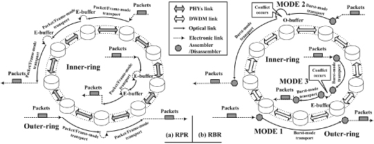
As shown in Figure 17.1, the same as RPR network, RBR adopts a bidirectional ring topology. That enables RBR to inherit all the best features of RPR. RBR adopts burst-mode data transmission scheme on the WDM ring network to implement the ultra-high-speed data transmission. Each data packet transmitted by RBR will be queued at the source node first and will then be assembled into an OBP before it is injected into the ring. After the burst-mode data transmission from the source node to the destination node, those packets will be disassembled at the destination node and then leave the RBR network.
Figure 17.1. Differences between RPR and RBR network. E, electronic; O, optical.
In more detail, when data packets arrive at an RBR node, they will be scheduled and then queue at the source node, according to the information carried by each packet, such as the destination node, the QoS class, and others. When the whole length of those packets to the same destination node is larger than the minimal burst length, or there are some packets that have waited for a maximum assembly time (i.e., the min-burst-length and max-assembly-period assembling algorithm [13]), they will be assembled into an OBP by the source node. After that, the source node will select a proper ringlet and a free wavelength for the generated OBP and create the corresponding ECP that carries the information of the OBP. The ECP will be sent ahead of the OBP in order to allow enough time for the downstream nodes to reconfigure. Then, a proper offset time later, the OBP will be sent out on the selected data wavelength. The ECP will be processed electronically at each downstream node to reserve the resources for the corresponding OBP going through successfully. When the OBP arrives at the destination node, it will be dissembled and the electronic data packets in it will be scheduled and then exported.
Actually, the assembling, disassembling, and the resource reservation approaches of the above burst-mode data transmission are the same as those in the OBS technology. Since burst-mode all-optical transmission avoids the by-hop electronic data processing at the intermedial nodes, RBR can perform more efficiently than RPR. Moreover, because RBR does not use tokens to resolve the bursts’ contentions, its network performance is also better than the OBT technology.
17.2.2 Hierarchical Model of RBR
The hierarchical model of RBR is shown in Figure 17.2. It can be divided into two sublayers, the electronic sublayer (ESL) and the optical sublayer (OSL).
Figure 17.2. Hierarchical model of RBR. OAM stands for Operation, Administration, and Maintenance. E, electronic; O, optical.
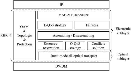
The ESL implements medium access control (MAC), inherited QoS strategy (E-QoS strategy), and fairness scheme from RPR. Besides, it can realize the function of the assembling and disassembling between the EDPs and the OBPs. Moreover, resource reservation, QoS strategy (O-QoS strategy), and conflicts resolution for OBPs in the OSL are also performed in the ESL.
The OSL provides the interface to the WDM layer and implements the burst-mode all-optical data transmission. It can perform the OBP-based adding and dropping operations, as well as the optical buffering schemes.
In addition, there is an exclusive Operation, Administration, and Maintenance (OAM) [14] module in RBR. It is used not only to implement the control of the two sublayers and harmonize their works, but also to perform the topology and fault management and the network performance management.
17.2.3 Two-Layer Buffering Scheme
The two-layer buffering scheme is used to resolve the conflicts of the OBP in the OSL. In accordance with the name of the two sublayers of RBR, the two-layer buffers are the optical buffer (O-buffer) for the OBPs in the OSL and the electronic buffer (E-buffer) for the electronic packets in the ESL. The O-buffer is implemented by the fiber delay lines (FDL) and the E-buffer is realized by the electronic buffers, such as the assembling/disassembling buffers at each RBR node.
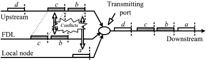
When the conflict between an OBP to be forwarded and an OBP being inserted on the ring occurs at an RBR node, the node will buffer the OBP from the upstream with the O-buffer first and then export it directly to the downstream nodes. As shown in Figure 17.3, if OBP b reaches the local node at the time that OBP a is just being transmitted, conflict between OBP a and OBP b will occur. With the FDL, OBP b will be delayed. Then, if the arrival time of the following OBP from the upstream is not later than the time that the OBP in the O-buffer has been transmitted, the following OBP will be also delayed by the FDL, as shown in Figure 17.3. In other words, when O-buffer is used, if there is not enough available time between the two adjacent OBP from the upstream on the wavelength or the latter OBP is not received by the local node, all the following OBP will have to enter the FDL to avoid the conflict at the transmitting port.
Figure 17.3. Burst contentions in the RBR network.
When E-buffer is used, the OBP can be received by the intermedial RBR node, though it is not the destination of the OBP. After the O/E conversion and being disassembled, the OBP will be divided into data packets. Then, those data packets will be rescheduled and reassembled into a new OBP and retransmitted to the destination.
Obviously, the E-buffer scheme is an aggressive way to end the O-buffer data transmission mode. However, more importantly, it is the key scheme to make RBR inherit all the best features of RPR, including sharing the E-buffer of all the nodes on the ring, realizing the fairness of the traffic, recovering the network from incidents, and reducing the lost caused by link or node faults. In addition, it can make RBR support the TDM services, which has a quite strict restriction to the performance of the data transmission.
Since RBR adopts the burst-mode all-optical transmission scheme, a large electronic buffer should be required. That is the same as the electronic buffer required in the OBS edge node. For details on the parameters and performance of this electronic buffer, we refer the interested reader to reference 15. Finally, since O-buffer is much faster than E-buffer, the two-layer buffering scheme can make RBR provide flexible QoS strategy. Detailed discussions will be provided in Section 17.5.
17.2.4 Three-Mode Data Transmission Scheme
With the two sublayers and their buffering schemes, three different data transmission modes for the OBP can be provided in the RBR network.
- MODE 1: All-optical data transmission with no buffer.
- MODE 2: All-optical data transmission with O-buffer.
- MODE 3: Hybrid data transmission with E-buffer.
With the resource reservation by the ECP, if there is no conflict occurring, the OBP will be transmitted directly to the destination node through an all-optical path without any buffering. This is the all-optical data transmission with no buffer, as MODE 1 in Figure 17.1b shows.
However, resource contentions cannot be avoided in the burst-mode all-optical transmission. When resource contention occurs at an intermedial RBR node, the node will buffer the OBP from the upstream with the O-buffer first and then export it. That is the all-optical data transmission with O-buffer, as MODE 2 in Figure 17.1b shows.
Alternatively, when the conflict occurs, the OBP can also be buffered by the intermedial RBR node with the E-buffer. That is, the OBP can be received by the intermedial RBR node though it is not the destination of the OBP. After the O/E conversion and being disassembled, the OBP will be divided into data packets. Then, another burst-mode data transmission process from this intermedial RBR node to the destination will be performed. That is the hybrid data transmission with E-buffer, as MODE 3 in Figure 17.1b shows.
In the hybrid data transmission with E-buffer, packets in the OBP will be disassembled and rescheduled at the intermedial node after O/E conversion. It should be pointed out here that when those packets are being rescheduled by the intermedial RBR nodes, both Cut-through and Store-and-Forward algorithms [16] of RPR can be adopted in the RBR network. In more detail, when the Cut-through algorithm is adopted, the OBP received by the intermedial RBR node will be reassembled as soon as it is converted into electronic signals, and a separate transmitting buffer will be used to buffer those electronic packets. On the contrary, when the Store-and-Forward algorithm is adopted, no separate transmitting buffer will be used and those packets will queue with the packets of the intermedial RBR node. Obviously, the same as that in the RPR network, data packets transmitted by the Cut-through algorithm in the RBR network will have a better performance than by the Store-and-Forward algorithm.
17.3 NODE STRUCTURE OF THE RBR NETWORK
To implement the two-layer buffering scheme and the three-mode data transmission scheme, an appropriate RBR node structure is illustrated in Figure 17.4.
Figure 17.4. Node structure of the RBR network. ECP GEN/PRO, generator and processor of electronic control packets; WS, wavelength splitter; FDL, fiber delay lines; E, electronic; O, optical, TB, transmitting buffer; RB, receiving buffer; Mode 1, all-optical data transmission with no buffer; Mode 2, all-optical data transmission with O-buffer; Mode 3, hybrid data transmission with E-buffer.
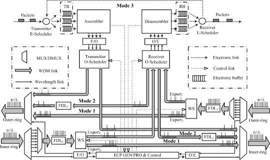
There are two electronic queuing buffers in the RBR node. One is the transmitting buffer, and the other is the receiving buffer. Both of them are used to buffer the electronic data packets. The function of the assembler and the disassembler are used to perform the conversions between the EDPs and the OBPs.
The O-scheduler is used to implement the selective connections and constructed by several 1 × 2 optical switches. For the transmitter O-scheduler, it is used to implement the alternative connection of the assembler to the two ringlets. For the receiver O-scheduler, it is used to implement the alternative connection of the wavelength splitter to the disassembler or the O-buffer.
The core component of the RBR node is the wavelength splitter (WS), which is used to implement the program-controlled wavelength splitting. When there are several wavelengths input into the wavelength splitter, with the different control signals, the wavelength splitter can divide those wavelengths into two different groups. As shown in more detail in Figure 17.4, different wavelengths will be exported from the Export1 of the wavelength splitter with the different control signals, while the rest will be exported from its Export2. This wavelength splitter can be realized by many optical devices, such as a tunable flitter like the acousto-optical tunable filter (AOTF), a certain number of 1 × 2 optical switches, and so on. The fast optical switches of the test-bed in reference 17 can be considered as a material form of the wavelength splitter. Since the wavelength splitter is only used to implement the wavelengths splitting, its cost will be much lower than that of the complex optical switch matrix in the OBS node.
There are two types of the FDL (FDL1 and FDL2) in the RBR node. FDL1 is used to compensate the processing delay of the corresponding ECP at the intermedial node. FDL2 acts as the O-buffer buffering the OBP exported from the wavelength splitter when conflict occurs.
The three-mode data transmission scheme is performed by the wavelength splitter and the O-schedulers. MODE 1 is the all-optical data transmission with no buffer. To achieve this, the wavelength splitter will let the wavelength that carrying an OBP from the upstream node directly go through the local node. As shown in Figure 17.4, when the wavelength is exported from FDL1, the wavelength splitter will export it through Export2 directly. On the contrary, for MODE 2 and MODE 3, the wavelength will be exported through the Export1 of the wavelength splitter. Then, the data transmission mode of the OBP on that wavelength will be decided by the receiver O-scheduler. With different connections of the wavelength splitter with FDL2 or the disassembler, different data transmission modes will be performed. In more detail, when the receiver O-scheduler connects the wavelength splitter with FDL2, the OBP exported from the wavelength splitter will enter FDL2 and then be exported to the downstream node. That is MODE 2, the all-optical data transmission with O-buffer. Otherwise, when the receiver O-scheduler connects the wavelength splitter with the disassembler, the OBP exported from the wavelength splitter will be disassembled by the local node. Then, the packets disassembled from the original OBP will be rescheduled and reassembled into a new OBP and will then be transmitted to the downstream node. That is MODE 3, the hybrid data transmission with E-buffer.
17.4 CONTROL SCHEME OF THE RBR NETWORK
The three-mode data transmission scheme in the RBR network is realized by a novel control protocol, which is called the Priority Only Destination Delay (PODD) protocol. This protocol is a variation of the Only Destination Delay (ODD) control protocol that was proposed in reference 18. In the ODD protocol, as the processing delay of the intermedial nodes is compensated by the FDL, the offset time between the bursts and their control packets is only related to the processing delay of the destination node. The difference between the PODD and ODD protocol is that the PODD protocol has an extra offset time that is used to guarantee the QoS of the OBP in terms of the lower blocking probability for the higher-priority OBP.
Besides, another key point of the PODD protocol is that the offset time between each OBP and its ECP is invariable during the whole transmission approach. This is used to keep the firm scheduling relationship between the OBP and its ECP and avoid the conflicts caused by the variable offset time. As shown in detail in Figure 17.5a, when the conflict between OBP a and OBP b occurs, the OBP a will be buffered by the FDL. When OBP a exports from the FDL, a new conflict between OBP a and OBP c will occur. All the controls and conflict solutions of the OBP are implemented by their ECP. If the offset time can be variable and the OBP c has already been delayed by the upstream node, its offset time will be changed from “Offset time” to “Offset time + TFDL2.” Since ECP c has already transmitted to the downstream node when ECP a arrives and OBP a cannot be buffered by the FDL again, there is no way to resolve the conflict and the packet loss will occur. On the contrary, if the offset time between each OBP and its ECP is invariable, since ECP c will arrive at the local node after ECP a, the conflict above can be resolved by buffering the OBP c at the local node again, as Figure 17.5b shows.
Figure 17.5. Control scheme of the RBR network. TFDL1 and TFDL2 are the length of FDL1 and FDL2 in Figure 17.3, respectively. S, source node; D, destination node; 1 to 3, intermedial nodes; TD, the processing time for the destination node; Tc, the extra offset time for higher priority OBP; δ, the ECP processing time for the intermedial node; L, the length of the OBP; MODE 1, all-optical data transmission with no buffer; MODE 2, all-optical data transmission with O-buffer; MODE 3, hybrid data transmission with E-buffer.
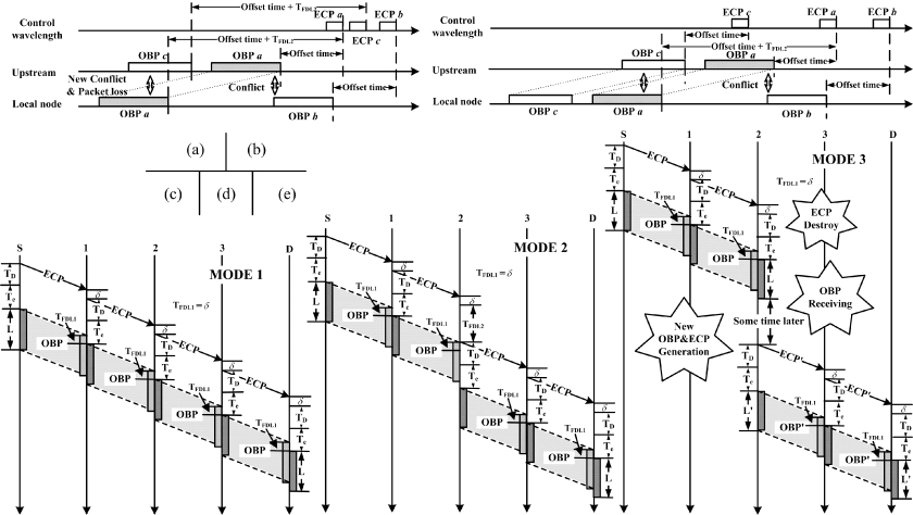
Detailed resource reservation schemes of the PODD control protocol in the three different data transmission modes are shown in Figure 17.5c–e. When there is no conflict, the OBP will be transmitted through an all-optical path. Each time it goes through an intermedial node, it will be delayed the length of FDL1, which is used to counteract the processing delay of the corresponding ECP, as shown in Figure 17.5c.
For the O-buffer mode, as shown in Figure 17.5d, when conflict occurs at node 2, the node will use FDL2 to resolve the resource contention. As a result, the corresponding OBP will be delayed the length of FDL2 more. Due to the reason discussed above, the ECP will be also delayed a period that is equal to the length of FDL2 by node 2 in order to keep the offset time between the OBP and its ECP invariable.
For the E-buffer mode, as shown in Figure 17.5e, the resource reservation can be considered as two independent all-optical data transmission processes. If node 2 decides to receive the OBP whose destination is node D, the corresponding ECP will be destroyed by node 2 first. When the OBP have been received by node 2, the packets will be rescheduled and reassembled there. Finally, a new OBP (OBP′) and its corresponding ECP (ECP′) will be created by node 2 and transmitted to Node D, respectively.
Finally, it should be pointed out here that in the PODD control protocol, the OBP with a high priority will have a long extra offset time and can adopt MODE 2 to resolve contentions, while the OBP with a low priority will have a short or even no extra offset time and can adopt MODE 3 to resolve contentions.
17.5 QOS STRATEGY OF THE RBR NETWORK
The two-sublayer architecture enables RBR to have more flexible QoS strategy. On the one hand, in the OSL, with the PODD control protocol, the QoS strategy for different class OBPs can be provided by the different extra offset time. That is, the OBP with a high priority will have a long extra offset time and the OBP with a low priority will have a short or even no extra offset time. On the other hand, in the ESL, with the QoS strategy and fairness algorithm inherited from RPR, QoS strategy of RBR can be provided by the Cut-Through and the Store-and-Forward data transmission schemes. Besides, in the RBR network, resource contentions caused by the OBPs with the high priority can be resolved by the optical buffering mode, while resource contentions caused by the OBPs with the low priority can be resolved by the electronic buffering mode.
Detailed QoS strategy of the RBR network is presented in Table 17.1. It can satisfy the different performance requirements of the different applications and services in the existing networks, such as audio, video, data applications, TDM services, and so on. In addition, it should be pointed out here that in order to implement the proposed QoS strategy in the RBR network, packets with different QoS class and different destination will be placed into different queues and then assembled into different OBPs at the source RBR node. Concerning the generated OBP, according to their different QoS classes, different transmission scheme will be performed.
TABLE 17.1. QoS Strategy of the RBR network
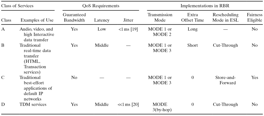
Note: MODE 1, All-optical data transmission with no buffer; MODE 2, all-optical data transmission with O-buffer; MODE 3, hybrid data transmission with E-buffer.
17.5.1 Audio and Video Applications
Audio and video applications here mean the real-time applications—for example, IP phone, video conference, and others. There are two major performance requirements for these kinds of audio and video applications: One is the low latency, and the other is the small jitter.
As shown in Table 17.1, because the all-optical data transmission modes (including the no buffer mode and the O-buffer mode) are adopted in Class A, it is easy to satisfy the requirement on the low latency. Concerning the requirement on jitter, because those applications are real-time and high interactive, jitter less than 1 ms [19] should be satisfied.
To do this, several parameters of the RBR network should be considered, including the maximum assembly time, the length of the O-buffer, and the maximum number of the nodes on the ring. If we define that Tassemble is the maximum assembly time, TO-buffer is the length of the O-buffer, and h represents the hops from the source node to the destination node, the maximum jitter Jmax of the packets transmitted by all-optical data transmission modes can be calculated by Eq. (17.1).
From Eq. (17.1), we can see that if we assume that the maximum assembly time of the bursts is 500 µs and the latency of the O-buffer at each RBR node is 50 µs, to satisfy the requirement on jitter that is less than 1 ms, the maximum hops from the source RBR node to the destination RBR node should be not more than 10. In other words, the maximum number of the node on the ring should not exceed 21.
Compared with the other applications, real-time audio and video applications need a higher priority. Therefore, to reduce the conflict probability of those packets, a long extra offset time is adopted in QoS Class A.
17.5.2 Data Applications
Data applications can be divided into three types: the high interactive data applications, the traditional real-time data applications, and the non-real-time data applications with the scheme of best effort. Different data applications have different performance requirements [19]. According to their different performance requirements, different QoS classes are provided in the RBR network.
First, for the high interactive data transfer, such as interactive games, telnet, command/control, and so on, because those applications have the same performance requirement on latency as the real-time audio and video applications [19], the data transmission modes for those applications provided by the RBR network are the same as those for the real-time audio and video applications, as shown in Table 17.1.
Then, as the traditional real-time data applications, including Web browsing, E-mail (server access), high-priority transaction services (E-commerce), bulk data, still image, fax (“real-time”), and so on, can abide a certain bound of latency [19] and have a lower priority compared with the applications in QoS class A, RBR adopts the e-buffer data transmission mode with a short extra offset time to transmit those applications, as QoS Class B in Table 17.1 shows. In addition, when the E-buffer is used during their transmission, to ensure their performance requirement on the latency, the Cut-though data transmission algorithm is adopted.
Finally, QoS Class C of the RBR network is applied to all the non-real-time data applications with the scheme of best effort. The non-real-time data applications include E-mail (server to server transfer), low-priority transaction services, usenet, fax (store and forward), and so on. The same as QoS Class B, E-buffer data transmission mode can be adopted in QoS class C. Moreover, because those non-real-time data applications have no special performance requirements and have the lowest priority among all the applications, when E-buffer is used during their transmission, the Store-and-Forward data transmission algorithm and the fairness algorithm can be adopted in the RBR network.
17.5.3 TDM Services
Although Internet traffic has been explosively grown in the existing networks, TDM service still plays an important role in data transmission due to its high quality service. TDM support is an important feature of the next-generation Metropolitan Area Network. However, to realize the transmission of the TDM traffic with the jitter much less than 1 ms [20] in the RBR network, it means that all those OBP that contain TDM frames should have the same processing time at each intermedial RBR node. Therefore, in order to support the TDM services, RBR provides a by-hop electronic data transmission mode. It can set up a steady data transmission pipeline for the TDM services and realize the transmission with the jitter much less than 1 ms.
The assembling and disassembling schemes for the TDM frames are the same as those for the other data packets. When the TDM frames arrive at an RBR node, they will be buffered in the transmitting buffer first. TDM traffic is characterized as length-fixed and interarrival-time-fixed. Therefore, regardless of whether the assembling scheme is time-based or length-based, the generated OBP traffic that contains TDM frames will be also characterized as length-fixed and interarrival-time-fixed. Because all the other data transmission modes will bring the delay variation when conflicts between OBP occur, the by-hop electronic processing is the best choice, and concerning the frames rescheduling algorithm at each node, Cut-Through algorithm, is the optimal option compared with Store-and-Forward algorithm, which will make the packets have different queuing delay.
17.6 PERFORMANCE EVALUATION OF THE RBR NETWORK
Different parameters setting will provide different data transmission performance in the RBR network. This enables the RBR network to satisfy the performance requirements of all the applications and services in the existing networks.
By computer simulations, a 17-node RBR network is used to investigate the data transmission performance. There are 10 data wavelengths in each ringlet, and the data transmission rate of each wavelength is 10 Gbit/s. The distance between each two adjacent RBR nodes is 10 km, and the processing delay of ECP at each RBR node is 50 ns.
Figure 17.6a–c plot the transmission latency and jitter of traffic with different QoS classes between two given RBR nodes under different network load conditions. Latency is measured from the time that a packet or TDM frame arrives at an RBR node to the time that it leaves its destination node. The average latency in Figure 17.6 is defined in each 10 ms of the simulation time.
Figure 17.6. Transmission latency for different QoS class traffic in the RBR network with different network load. (a) Low network load. (b) Middle network load. (c) High network load.
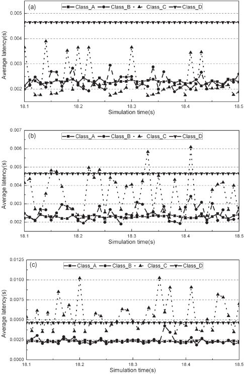
From Figure 17.6, we can see that with the different data transmission modes, the transmission latency and jitter of the different QoS classes are different. For class A, with the all-optical data transmission mode, they have a very low latency and a small jitter. However, for class B and C, with the adoption of the E-buffer mode, they have a high latency and a large jitter. Concerning class D, with the by-hop E-buffer mode and Cut-Through algorithm, its transmission latency is almost a straight line.
Moreover, it should also be observed that the impact on the traffic with different QoS classes caused by the variation of the network load is different. Traffic with QoS class C is the most sensitive to the change of the network load. The transmission latency and jitter of the traffic with QoS class C under the high network load condition are much higher than that under the low network load condition. That is because they carry the traditional best-effort applications of default IP networks and have the lowest priority in the RBR network. Concerning traffic with QoS class A and D, as shown in Figure 17.6, they are insensitive to the change of the network load. That is because they have the highest priority in the RBR network and adopt the by-hop E-buffer transmission mode, respectively.
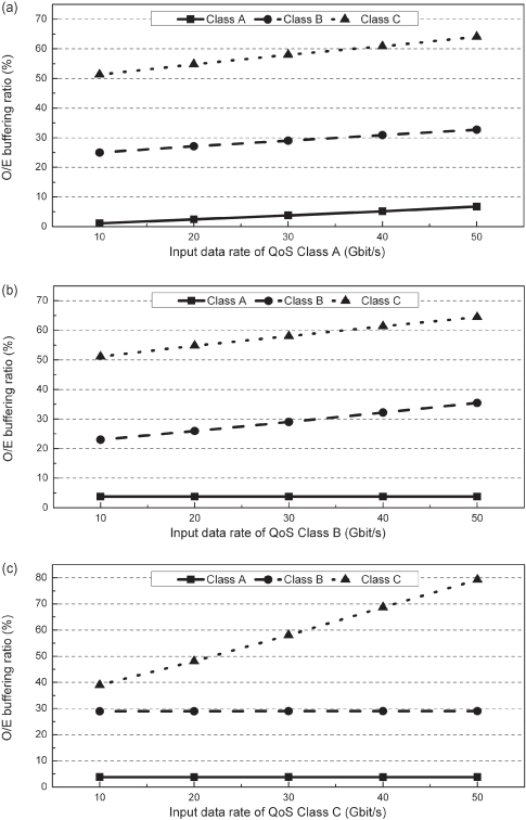
On the other hand, we also investigate the influence of the variation of the different class traffic on the QoS performance of the RBR network. The simulation results have been shown in Figure 17.7. The O/E buffering ratio is defined as the ratio of the packets; that have been transmitted through the O-buffer mode or the E-buffer mode to all the packets with the same QoS class that have been transmitted. This parameter shows the conflict probability of the packets; and the higher it is, the longer the average packets’ latency is. From Figure 17.7, we can see that with the different extra offset time for different class traffic, each class packet will have different O/E buffering ratio. In Figure 17.7a, when all the data input rate of the three classes traffic are 30 Gbit/s, the O-buffering ratio of packets with class A is only 3.7%, while the E-buffering ratio of packets with class B and C are 29% and 58%, respectively. This is because the long extra offset time makes the packets have a high reservation priority. The longer the extra offset time, the lower the conflict probability and the lower the buffering ratio. Moreover, comparing the three parts of Figure 17.7, we can see that another function of the extra offset time is that it make the variation of the low class traffic have no influence on the transmission performance of the high-lass traffic. As shown in Figures 17.7b and 17.7c, no matter how much the input data rate of the class B and C traffic is, the O-buffering ratio of the packets with class A is always invariable.
Figure 17.7. Influence of the variation of the different class traffic on the QoS performance of the RBR network. (a) The data input rates of QoS class B and C are 30 Gbit/s. (b) The data input rates of QoS class A and C are 30 Gbit/s. (c) The data input rates of QoS class A and B are 30 Gbit/s.
17.7 CONCLUSIONS
The world of transport is on the verge of significant change. The days of T1/E1s being the driving force are fading as packet services and high-capacity access networks grow. To meet the ever-increasing demand for bandwidth and network flexibility, integrating the resilient packet ring with the intelligent WDM, a novel network technology for the next-generation Metropolitan Area Network, which is called a resilient burst ring (RBR), is presented in this chapter. It can implement the WDM-supported ultra-high-speed carrier-grade data transmission with scalability and reliability.
We can now summarize the RBR network with the following features:
1. Two-Sublayer Architecture and the Corresponding Buffering Schemes. With the two-sublayer architecture, RBR can inherit all the advantages of RPR and implement the burst-mode ultra-high-speed data transmission in the WDM ring networks. With the two-layer buffering scheme, RBR can resolve the conflicts in the optical domain completely.
2. Three-Mode Data Transmission Scheme and the Corresponding Control Algorithms. With the proposed Priority Only Destination Delay (PODD) protocol in the OSL and the Cut-Through and Store-and-Forward algorithms inherited from RPR in the ESL, both the ultra-high-speed data transmission and the carrier-grade services are realized.
3. Flexible QoS Strategy. With the different parameter setting and different data transmission modes, RBR can satisfy the requirements of all the applications and services in the existing networks.
4. TDM Services Support. The steady data transmission pipeline set up by the by-hop electronic processing with Cut-Through algorithm at each intermedial node can realize the synchronous data transmission on the packet-based optical transport network.
On all accounts, with the four features above, RBR will be a very competitive solution for the next-generation ultra-high-speed Metropolitan Area Networks.
REFERENCES
1. T. Hills, Next-Gen SONET, Lightreading Rep. [Online]. Available on http://www.lightreading.com/document.asp?doc_id=14781, 2002.
2. L. Choy, Virtual concatenation tutorial: Enhancing SONET/SDH networks for data transport, J. Opt. Networking, Vol. 1, No. 1, pp. 18–29, December 2001.
3. Resilient packet ring (RPR) IEEE 802.17.
4. F. Davik, M. Yilmaz, S. Gjessing, and N. Uzun, IEEE 802.17, Resilient packet ring tutorial, IEEE Commun. Mag., Vol. 42, No. 3, pp. 112–118, March 2004.
5. C. Qiao and M. Yoo, Optical burst switching (OBS)—A new paradigm for an optical internet, J. High Speed Networks, Vol. 8, pp. 69–84, 1999.
6. Y. Sun, T. Hashiguchi, V. Q. Minh, X. Wang, H. Morikawa, and T. Aoyama, Design and implementation of an optical burst-switched network testbed, IEEE Commun. Mag., Vol. 43, No. 11, pp. 48–55, November 2005.
7. J. Kim, J. Cho, S. Das, D. Gutierrez, M. Jain, C.-F. Su, R. Rabbat, T. Hamada, and L. G. Kazovsky, Optical burst transport: A technology for the WDM metro ring networks, J. Lightwave Technol., Vol. 25, No. 1, pp. 93–102, January 2007.
8. J. Kim, M. Maier, T. Hamada, and L. G. Kazovsky, OBT: Optical burst transport in metro area networks, IEEE Commun. Mag., Vol. 45, No. 11, pp. 44–51, November 2007.
9. L. Xu, H. G. Perros, and G. N. Rouskas, Access protocols for optical burst-switched ring networks. Information Sci., Vol. 149, 75–81, 2003.
10. X. Liu, G. Wen, H. Wang, and Y. Ji, Analyses, simulations, and experiments on the performance of the token-based optical burst transport ring networks, in Proceedings of SPIE—The International Society for Optical Engineering, Optical Transmission, Switching, and Subsystems, 2007.
11. X. Liu, H. Wang, and Y. Ji, Resilient burst ring: Extend IEEE 802.17 to WDM networks, IEEE Commun. Mag., Vol. 46, No. 11, pp. 74–81, November 2008.
12. Metro Ethernet Forum. http://www.metroethernetforum.org/
13. X. Cao, J. Li, Y. Chen, and C. Qiao, Assembling TCP/IP packets in optical burst switched networks, in IEEE Globecom 2002, Taipei, Taiwan, 2002, 11.
14. D. O’Connor, Ethernet service OAM—Overview, applications, deployment, and issues,” in OFC2006, NWF2, 5–10 March 2006.
15. H. Li and I. Thng, Edge node buffer usage in optical burst switching networks, Photonic Network Commun., Vol. 13, No. 1, pp. 31–51, January 2007.
16. D. A. Schupke and A. Riedl, Packet transfer delay comparison of a store-and-forward and a cut-through resilient packet ring, Proc. Broadband Communi., pp. 12-1–12-5, 2002.
17. H. Yoo, J. P. Park, S. Han, J. S. Cho, Y. H. Won, M. S. Lee, M. H. Kang, Y.-K. Seo, K. J. Park, C. J. Youn, H. C. Kim, J.-K. Rhee, and S. Y. Park, Microsecond optical burst add–drop multiplexing for WDM ring networks, in OFC2006, OWP6, March 5–10 2006.
18. L. Xu, H. G. Perros, and G. N. Rouskas, A simulation study of optical burst switching access protocols for WDM ring networks, in Networking 2002, LNCS 2345, pp. 863–874.
19. ITU-T Recommendation G.1010 (11/2001), End-User Multimedia QoS Categories.
20. ITU-T Recommendation G.825 (03/2000), The Control of Jitter and Wander within Digital Networks which Are Based on the Synchronous Digital Hierarchy (SDH).