
Figure 5-1: The seven layers of the OSI model.
The OSI Reference Model
In 1984, the International Organization for Standardization (ISO) adopted the Open Systems Interconnection (OSI) Reference Model (or simply, the OSI model) to facilitate interoperability between network devices independent of the manufacturer. The OSI model defines standard protocols for communication and interoperability by using a layered approach. This approach divides complex networking issues into simpler functional components that help the understanding, design, and development of networking solutions and provides the following specific advantages:
![]() Clarifies the general functions of a communications process, instead of focusing on specific issues
Clarifies the general functions of a communications process, instead of focusing on specific issues
![]() Reduces complex networking processes into simpler sub-layers and components
Reduces complex networking processes into simpler sub-layers and components
![]() Promotes interoperability by defining standard interfaces
Promotes interoperability by defining standard interfaces
![]() Aids development by allowing vendors to change individual features at a single layer, instead of rebuilding the entire protocol stack
Aids development by allowing vendors to change individual features at a single layer, instead of rebuilding the entire protocol stack
![]() Facilitates easier (and more logical) troubleshooting
Facilitates easier (and more logical) troubleshooting
The OSI model consists of seven distinct layers that describe how data is communicated between systems and applications on a computer network, as shown in Figure 5-1. These layers include
![]() Application (Layer 7)
Application (Layer 7)
![]() Presentation (Layer 6)
Presentation (Layer 6)
![]() Session (Layer 5)
Session (Layer 5)
![]() Transport (Layer 4)
Transport (Layer 4)
![]() Network (Layer 3)
Network (Layer 3)
![]() Data Link (Layer 2)
Data Link (Layer 2)
![]() Physical (Layer 1)
Physical (Layer 1)
 Try creating a mnemonic to recall the layers of the OSI model, such as: Adult People Should Try New Dairy Products.
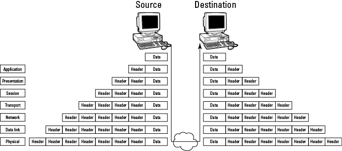
In the OSI model, data is passed from the highest layer (Application; Layer 7) downward through each layer to the lowest layer (Physical; Layer 1), and is then transmitted across the network medium to the destination node, where it’s passed upward from the lowest layer to the highest layer. Each layer communicates only with the layer immediately above and below it (adjacent layers). This communication is achieved through a process known as data encapsulation. Data encapsulation wraps protocol information from the layer immediately above in the data section of the layer immediately below. Figure 5-2 illustrates this process.
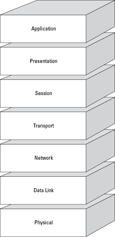
Figure 5-2: Data encapsulation in the OSI model.
Fill-in-the-blank area networks (__AN)
Although networks are generally classified as LANs or WANs, you should familiarize yourself with a number of variations (and acronyms) — if for no other reason than to put together a winning combination in a friendly game of Scrabble:
![]() Personal area network (PAN): Connects an individual’s electronic devices to each other or to a larger network, such as the Internet. Examples of devices that might be connected via a PAN include laptop computers, cellular phones, PDAs (personal digital assistants), and other mobile devices (such as BlackBerries and iPods). These devices can be connected via wired technologies such as USB and FireWire, or wireless technologies such as Wi-Fi, Bluetooth, and IrDA (Infrared Data Association). A wireless PAN is also sometimes referred to as a WPAN (that’s worth nine points in Scrabble!).
Personal area network (PAN): Connects an individual’s electronic devices to each other or to a larger network, such as the Internet. Examples of devices that might be connected via a PAN include laptop computers, cellular phones, PDAs (personal digital assistants), and other mobile devices (such as BlackBerries and iPods). These devices can be connected via wired technologies such as USB and FireWire, or wireless technologies such as Wi-Fi, Bluetooth, and IrDA (Infrared Data Association). A wireless PAN is also sometimes referred to as a WPAN (that’s worth nine points in Scrabble!).
![]() Storage area network (SAN): Connects servers to a separate physical storage device (typically a disk array). The server operating system sees the storage as if it were directly attached to the server. SANs typically comprise several terabytes or more of disk storage and incorporate highly sophisticated design architectures for fault tolerance and redundancy. Communications protocols used in SANs typically include SCSI (Small Computer System Interface, or “Scuzzy”), iSCSI (IP-based SCSI), Fibre Channel Protocol (FCP, SCSI over Fibre Channel), and FCoE (Fibre Channel over Ethernet). SANs are highly scalable, enable technologies such as virtualization and snapshots, provide flexibility in server deployment options, facilitate disaster recovery (for example, with real-time replication), and tend to reduce the overall cost of data storage.
Storage area network (SAN): Connects servers to a separate physical storage device (typically a disk array). The server operating system sees the storage as if it were directly attached to the server. SANs typically comprise several terabytes or more of disk storage and incorporate highly sophisticated design architectures for fault tolerance and redundancy. Communications protocols used in SANs typically include SCSI (Small Computer System Interface, or “Scuzzy”), iSCSI (IP-based SCSI), Fibre Channel Protocol (FCP, SCSI over Fibre Channel), and FCoE (Fibre Channel over Ethernet). SANs are highly scalable, enable technologies such as virtualization and snapshots, provide flexibility in server deployment options, facilitate disaster recovery (for example, with real-time replication), and tend to reduce the overall cost of data storage.
![]() Virtual local area network (VLAN): Implemented on network switches in a LAN as a way of logically grouping users and resources together. Often, such VLANs correlate to department functions (such as Accounting, Sales, and Research & Development) and/or IP subnets. VLANs provide scalability, segmentation, and (some) security at Layer 2 (see the section “The OSI Reference Model,” in this chapter) and can also work to limit the size of your Ethernet broadcast domains. VLANs are implemented by using IEEE 802.1q tagging to tag Ethernet frames with VLAN information.
Virtual local area network (VLAN): Implemented on network switches in a LAN as a way of logically grouping users and resources together. Often, such VLANs correlate to department functions (such as Accounting, Sales, and Research & Development) and/or IP subnets. VLANs provide scalability, segmentation, and (some) security at Layer 2 (see the section “The OSI Reference Model,” in this chapter) and can also work to limit the size of your Ethernet broadcast domains. VLANs are implemented by using IEEE 802.1q tagging to tag Ethernet frames with VLAN information.
![]() Wireless local area network (WLAN): Also known as a WiFi network. A wireless LAN that uses wireless access points (WAPs, or simply APs) to connect wireless-enabled devices to a wired LAN. We cover WLANs in more detail in the section “Wireless Network (WLAN) Security,” later in this chapter.
Wireless local area network (WLAN): Also known as a WiFi network. A wireless LAN that uses wireless access points (WAPs, or simply APs) to connect wireless-enabled devices to a wired LAN. We cover WLANs in more detail in the section “Wireless Network (WLAN) Security,” later in this chapter.
![]() Campus area network (CAN): Connects multiple buildings across a high-performance backbone.
Campus area network (CAN): Connects multiple buildings across a high-performance backbone.
![]() Metropolitan area network (MAN): Extends across a large area, such as a small city.
Metropolitan area network (MAN): Extends across a large area, such as a small city.
![]() Value-added network (VAN): A type of extranet that allows businesses within an industry to share information or integrate shared processes. For example, Electronic Data Interchange (EDI) allows organizations to exchange structured documents — such as order forms, purchase orders, bills of lading, and invoices — over a secure network.
Value-added network (VAN): A type of extranet that allows businesses within an industry to share information or integrate shared processes. For example, Electronic Data Interchange (EDI) allows organizations to exchange structured documents — such as order forms, purchase orders, bills of lading, and invoices — over a secure network.
Physical Layer (Layer 1)
The Physical Layer sends and receives bits across the network cabling from one device to another.
It specifies the electrical, mechanical, and functional requirements of the network, including network topology, cabling and connectors, and interface types, as well as the process for converting bits to electrical (or light) signals that can be transmitted across the physical medium. Various network topologies, made from copper or fiber-optic wires and cables, hubs, and other physical materials, comprise the Physical Layer.
Network topologies
The four basic network topologies in common use at the Physical Layer today are star, mesh, ring, and bus. Although many variations of the basic types (Fiber Distributed Data Interface [FDDI], star-bus, star-ring) exist, we stick to the basics in the following sections.
Star
In a star topology, each individual node on the network is directly connected to a switch, hub, or concentrator. (See Figure 5-3.) All data communications must pass through the switch (or hub), which can become a bottleneck or single point of failure. A star topology is ideal for practically any size environment and is the most common basic topology in use today. A star topology is also easy to install and maintain, and network faults are easily isolated without affecting the rest of the network.
Figure 5-3: A star topology.

Mesh
In a mesh topology, all systems are interconnected to provide multiple paths to all other resources. See Figure 5-4 for a logical illustration of a mesh topology. In Figure 5-4, if Link 1 between Routers 1 and 2 is down, those routers and the attached systems and networks can still communicate via Router 3 over Links 5 and 6.
Figure 5-4: A mesh topology.

In most networks, a partial mesh is implemented for only the most critical network components, such as routers, switches, and servers (by using multiple network interface cards [NICs] or server clustering) to eliminate single points of failure.
 See Chapter 6 for more on eliminating single points of failure.
Ring
A ring topology is a closed loop that connects end devices in a continuous ring (see Figure 5-5). Functionally, this is achieved by connecting individual devices to a Multistation Access Unit (MSAU or MAU). Physically, this setup gives the ring topology the appearance of a star topology. (See Figure 5-6.) Ring topologies are common in token-ring and FDDI networks. In a ring topology, all communication travels in a single direction around the ring.
Figure 5-5: A logical ring topology.

Figure 5-6: A physical ring topology.

Bus
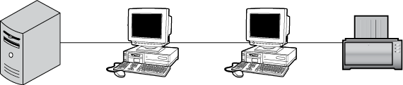
In a bus (or linear bus) topology, all devices are connected to a single cable (the backbone) that’s terminated on both ends. (See Figure 5-7.) Bus networks were commonly used for very small networks because they’re inexpensive and easy to install. However, in large environments, they’re impractical because the media has physical limitations, the backbone is a single point of failure (a break anywhere on the network affects the entire network), and tracing a fault in a large network can be extremely difficult. Bus networks are extremely rare today and are no longer the least-expensive or easiest-to-install network option.
Figure 5-7: A bus topology.
Cable and connector types
Cables carry the electrical or light signals that represent data between devices on a network. Data signaling is described by several characteristics, including type (see the sidebar “Analog and digital signaling,” in this chapter), control mechanism (see the sidebar “Asynchronous and synchronous communications,” in this chapter), and classification (either baseband or broadband). Baseband signaling uses a single channel for transmission of digital signals and is common in LANs that use twisted-pair cabling. Broadband signaling uses many channels over a range of frequencies for transmission of analog signals, including voice, video, and data. The four basic cable types used in networks are coaxial, twinaxial, twisted-pair, and fiber-optic.
Coaxial cable
Coaxial (abbreviated as coax and pronounced KOH-axe) cable was very common in the early days of LANs and is rebounding (sort of) with the emergence of broadband networks. Coax cable consists of a single, solid-copper-wire core, surrounded by a plastic or Teflon insulator, braided-metal shielding, and (sometimes) a metal foil wrap, all covered with a plastic sheath. This construction makes the cable very durable and resistant to Electromagnetic Interference (EMI) and Radio Frequency Interference (RFI) signals. Coax cable is commonly used to connect cable or satellite television receivers (the cable that goes from the black box to the wall).
Coax cable comes in two flavors, thick and thin:
![]() Thick: Also known as RG8 or RG11 or thicknet. Thicknet cable uses a screw-type connector, known as an Attachment Unit Interface (AUI).
Thick: Also known as RG8 or RG11 or thicknet. Thicknet cable uses a screw-type connector, known as an Attachment Unit Interface (AUI).
![]() Thin: Also known as RG58 or thinnet. Thinnet cable is typically connected to network devices by using a bayonet-type connector, known as a BNC (Bayonet Neill-Concelman) connector.
Thin: Also known as RG58 or thinnet. Thinnet cable is typically connected to network devices by using a bayonet-type connector, known as a BNC (Bayonet Neill-Concelman) connector.
Twinaxial cable
Twinaxial (also known as twinax) cable is very similar to coax cable, but it consists of two solid copper-wire cores, rather than a single core. Twinax is used to achieve high data transmission speeds (for example, 10 Gb Ethernet [abbreviated as GE, GbE or GigE]) over very short distances (for example, 10 meters) at a relatively low cost. Typical applications for twinax cabling include SANs and top-of-rack network switches that connect critical servers to a high-speed core. Other advantages of twinax cabling include lower transceiver latency (delay in transmitter/receiver devices) and power consumption (compared to 10 GbE twisted-pair cables), and low bit error ratios (BERs).
 Bit error ratio (BER) is the ratio of incorrectly received bits to total received bits over a specified period of time.
Twisted-pair cable
Twisted-pair cable is the most popular LAN cable in use today. It’s lightweight, flexible, inexpensive, and easy to install. One easily recognized example of twisted-pair cable is common telephone wire. Twisted-pair cable consists of four copper-wire pairs that are twisted together to improve the transmission quality of the cable by reducing crosstalk and attenuation. The tighter the twisted pairs, the better the transmission speed and quality. Crosstalk occurs when a signal transmitted over one channel or circuit negatively affects the signal transmitted over another channel or circuit. An (ancient) example of crosstalk occurred over analog phone lines when you could hear parts of other conversations over the phone. Attenuation is the gradual loss of intensity of a wave (for example, electrical or light) while it travels over (or through) a medium.
Currently, ten categories of twisted-pair cabling exist, although only four (Cat 3, Cat 5e, Cat 6, and Cat 6a) are currently defined as standards by the TIA/EIA (Telecommunications Industry Association/Electronics Industries Alliance). Cat 5, Cat 5e, and Cat 6 cable are typically used for networking today. (See Table 5-1.)
The International Organization of Standardization (ISO) also defines cabling standards corresponding to the TIA/EIA standards and including some of the other cabling categories. These standards include Class D (Cat 5e), Class E (Cat 6), Class EA (Cat 6a), Class F (Cat 7), and Class FA (Cat 7a).
Twisted-pair cable can be either unshielded (UTP) or shielded (STP). UTP cabling is more common because it’s easier to work with and less expensive than STP. STP is used when noise is a problem or when security is a major concern. Noise is produced by external sources and can distort or otherwise impair the quality of a signal. Examples of noise include RFI and EMI from sources such as electrical motors, radio signals, fluorescent lights, microwave ovens, and electronic equipment. Shielded cabling also reduces electromagnetic emissions that may be intercepted by an attacker.
 TEMPEST is a (previously classified) U.S. military term that refers to the study of electromagnetic emissions from computers and related equipment.
Cat 7 and Cat 7a cable is available as STP only. In addition to the entire Cat 7 or Cat 7a cable, the individual wire pairs are also shielded.
Twisted-pair cable is terminated with an RJ-type terminator. The three common types of RJ-type connectors are RJ-11, RJ-45, and RJ-49. Although these connectors are all similar in appearance (particularly RJ-45 and RJ-49), only RJ-45 connectors are used for LANs. RJ-11 connectors are used for analog phone lines, and RJ-49 connectors are commonly used for Integrated Services Digital Network (ISDN) lines and WAN interfaces.
Table 5-1 Twisted-Pair Cable Categories
|
Category |
Use and Speed |
Example |
|
1 (not a TIA/EIA standard) |
Voice only |
Telephone |
|
2 (not a TIA/EIA standard) |
Data (up to 4 Mbps) |
Token-ring at 4 Mbps |
|
3 |
Data (up to 10 Mbps) and voice |
Ethernet and telephone |
|
4 (not a TIA/EIA standard) |
Data (up to 20 Mbps) |
Token-ring at 16 Mbps |
|
5 (not a TIA/EIA standard) |
Data (up to 100 Mbps) |
Fast Ethernet |
|
5e |
Data (up to 1000 Mbps at 100 MHz) |
Gigabit Ethernet |
|
6 |
Data (up to 1000 Mbps at 250 MHz) |
Gigabit Ethernet |
|
6a |
Data (up to 10 Gbps at 500 MHz) |
10 Gigabit Ethernet |
|
7 (not a TIA/EIA standard) |
Data (up to 10 Gbps at 600 MHz up to 100 meters) |
10 Gigabit Ethernet |
|
7a (not a TIA/EIA standard) |
Data (up to 100 Gbps at 1000 MHz up to 15 meters) |
40 Gigabit Ethernet |
Cat 7 and 7a cabling is terminated by using various non-RJ-type connectors.
Fiber-optic cable
Fiber-optic cable, the most expensive type of network cabling — but also the most reliable — is typically used in backbone networks and high-availability networks (such as FDDI). Fiber-optic cable carries data as light signals, rather than as electrical signals. Fiber-optic cable consists of a glass core or bundle, a glass insulator (commonly known as cladding), Kevlar fiber strands (for strength), and a polyvinyl chloride (PVC) or Teflon outer sheath. Advantages of fiber-optic cable include high speeds, long distances, and resistance to interception and interference. Fiber-optic cable is terminated with an SC-type, ST-type, or LC-type connector.
See Table 5-2 for a comparison of the various cable types and their characteristics.
Ethernet designations, such as 10Base-T or 100Base-TX, refer to the speed of the cable and the signaling type (baseband). The last part of the designation is less strictly defined. It may refer to the approximate maximum length (as in 10Base-2 and 10Base-5), the type of connector (as in 10Base-T, 100Base-TX, and 100Base-F), or the type and speed of the connector (as in 1000Base-T/GbE).

Interface types
The interface between the Data Terminal Equipment (DTE) and Data Communications Equipment (DCE), which we discuss in the following section, is specified at the Physical Layer.
Network topologies, cable and connector types, and interfaces are defined at the Physical Layer of the OSI model.
Common interface standards include
![]() EIA/TIA-232: This standard supports circuits at signal speeds of up to 115,200 bits per second (formerly known as RS-232).
EIA/TIA-232: This standard supports circuits at signal speeds of up to 115,200 bits per second (formerly known as RS-232).
![]() EIA/TIA-449: A faster version of EIA/TIA-232, this standard supports longer cable runs and speeds of up to 2 Mbps.
EIA/TIA-449: A faster version of EIA/TIA-232, this standard supports longer cable runs and speeds of up to 2 Mbps.
![]() V.24. CCITT: Formerly ITU-T. This standard is essentially the same as the EIA/TIA-232 standard.
V.24. CCITT: Formerly ITU-T. This standard is essentially the same as the EIA/TIA-232 standard.
![]() V.35. CCITT: Formerly ITU-T. This standard describes a synchronous communications protocol between network access devices and a packet network that supports speeds of up to 48 Kbps.
V.35. CCITT: Formerly ITU-T. This standard describes a synchronous communications protocol between network access devices and a packet network that supports speeds of up to 48 Kbps.
![]() X.21bis. CCITT: Formerly ITU-T. This standard defines the communications protocol between DCE and DTE in an X.25 network. It’s essentially the same as the EIA/TIA-232 standard.
X.21bis. CCITT: Formerly ITU-T. This standard defines the communications protocol between DCE and DTE in an X.25 network. It’s essentially the same as the EIA/TIA-232 standard.
![]() High-Speed Serial Interface (HSSI): This network standard was developed to address the need for high-speed (up to 52 Mbps) serial connections over WAN links.
High-Speed Serial Interface (HSSI): This network standard was developed to address the need for high-speed (up to 52 Mbps) serial connections over WAN links.
Networking equipment
Networking devices that operate at the Physical Layer include network interface cards (NICs), network media (cabling, connectors, and interfaces, all of which we discuss in the section “Cable and connector types,” earlier in this chapter), repeaters, and hubs.
Network interface cards (NICs) are used to connect a computer to the network. NICs may be integrated on a computer motherboard or installed as an adapter card, such as an ISA, PCI, or PC card. Similar to a NIC, a WIC (WAN interface card) contains a built-in CSU/DSU and is used to connect a router to a digital circuit. Variations of WICs include HWICs (high-speed WAN interface cards) and VWICs (voice WAN interface cards).
A repeater is a non-intelligent device that simply amplifies a signal to compensate for attenuation (signal loss) so that one can extend the length of the cable segment.
A hub (or concentrator) is used to connect multiple LAN devices together, such as servers and workstations. The two basic types of hubs are
![]() Passive: Data enters one port and exits all other ports without any signal amplification or regeneration.
Passive: Data enters one port and exits all other ports without any signal amplification or regeneration.
![]() Active: Combines the features of a passive hub and repeater. Also known as a multi-port repeater.
Active: Combines the features of a passive hub and repeater. Also known as a multi-port repeater.
A switch is used to connect multiple LAN devices together. Unlike a hub, a switch doesn’t send outgoing packets to all devices on the network, but instead sends packets only to actual destination devices. A switch typically operates at the Data Link Layer (discussed in the following section), but the physical interfaces (the RJ-45 input connections) are defined at the Physical Layer.
Data Link Layer (Layer 2)
The Data Link Layer ensures that messages are delivered to the proper device across a physical network link. This layer also defines the networking protocol (for example, Ethernet and token-ring) used to send and receive data between individual devices. The Data Link Layer formats messages from layers above into frames for transmission, handles point-to-point synchronization and error control, and can perform link encryption.
We go into detail about link encryption in Chapter 8.
The Data Link Layer consists of two sub-layers: the Logical Link Control (LLC) and Media Access Control (MAC) sub-layers. (See Figure 5-8.)
Figure 5-8: The LLC and MAC sub-layers.

The Data Link Layer is responsible for ensuring that messages are delivered to the proper device across a physical network link.
The LLC sub-layer operates between the Network Layer above and the MAC sub-layer below. The LLC sub-layer performs the following three functions:
![]() Provides an interface for the MAC sub-layer by using Source Service Access Points (SSAPs) and Destination Service Access Points (DSAPs).
Provides an interface for the MAC sub-layer by using Source Service Access Points (SSAPs) and Destination Service Access Points (DSAPs).
![]() Manages the control, sequencing, and acknowledgement of frames being passed up to the Network Layer or down to the Physical Layer.
Manages the control, sequencing, and acknowledgement of frames being passed up to the Network Layer or down to the Physical Layer.
![]() Bears responsibility for timing and flow control. Flow control monitors the flow of data between devices to ensure that a receiving device, which may not necessarily be operating at the same speed as the transmitting device, isn’t overwhelmed.
Bears responsibility for timing and flow control. Flow control monitors the flow of data between devices to ensure that a receiving device, which may not necessarily be operating at the same speed as the transmitting device, isn’t overwhelmed.
The Logical Link Control (LLC) and Media Access Control (MAC) are sub-layers of the Data Link Layer.
The MAC sub-layer operates between the LLC sub-layer above and the Physical Layer below. It’s primarily responsible for framing and has the following three functions:
![]() Performs error control: Error control uses a cyclic redundancy check (CRC). A CRC is a simple mathematical calculation or checksum used to create a message profile (analogous to a simple message digest, which we discuss in Chapter 8). The CRC is recalculated by the receiving device. If the calculated CRC doesn’t match the received CRC, the packet is dropped and a request to re-send is transmitted back to the device that sent it.
Performs error control: Error control uses a cyclic redundancy check (CRC). A CRC is a simple mathematical calculation or checksum used to create a message profile (analogous to a simple message digest, which we discuss in Chapter 8). The CRC is recalculated by the receiving device. If the calculated CRC doesn’t match the received CRC, the packet is dropped and a request to re-send is transmitted back to the device that sent it.
![]() Identifies hardware device (or MAC) addresses: A MAC address (also known as a hardware address or physical address) is a 48-bit address that’s encoded on each device by its manufacturer. The first 24 bits identify the manufacturer or vendor. The second 24 bits uniquely identify the device.
Identifies hardware device (or MAC) addresses: A MAC address (also known as a hardware address or physical address) is a 48-bit address that’s encoded on each device by its manufacturer. The first 24 bits identify the manufacturer or vendor. The second 24 bits uniquely identify the device.
![]() Controls media access: The three basic types of media access are
Controls media access: The three basic types of media access are
• Contention: In contention-based networks, individual devices must vie for control of the physical network medium. This type of network is ideally suited for networks characterized by small bursts of traffic. Ethernet networks use a contention-based method, known as Carrier-Sense Multiple Access Collision Detect (CSMA/CD), in which all stations listen for traffic on the physical network medium. If the line is clear, any station can transmit data. However, if another station attempts to transmit data at the same time, a collision occurs, the traffic is dropped, and both stations must wait a random period of time before attempting to re-transmit. Another slight variation of the CSMA/CD method, used in Apple LocalTalk networks, is known as Carrier-Sense Multiple Access Collision Avoidance (CSMA/CA).
• Token-passing: In token-passing networks, individual devices must wait for a special frame, known as a token, before they transmit data across the physical network medium. This type of network is considered deterministic (transmission delay can be reliably calculated, and collisions don’t occur) and is ideally suited for networks that have large, bandwidth-consuming applications that are delay-sensitive. Token-ring, FDDI, and ARCnet networks all use various token-passing methods for media access control.
• Polling: In polling networks, individual devices (secondary hosts) are polled by a primary host to see whether they have data to be transmitted. Secondary hosts can’t transmit until permission is granted by the primary host. Polling is typically used in mainframe environments.
LAN protocols and transmission methods
Common LAN protocols are defined at the Data Link (and Physical) Layer. They include the following:
![]() ARCnet: The ARCnet protocol is one of the earliest LAN technologies developed. It transports data to the physical LAN medium by using the token-passing media access method that we discuss in the preceding section. It’s implemented in a star topology by using coaxial cable. ARCnet provides slow-but-predictable network performance.
ARCnet: The ARCnet protocol is one of the earliest LAN technologies developed. It transports data to the physical LAN medium by using the token-passing media access method that we discuss in the preceding section. It’s implemented in a star topology by using coaxial cable. ARCnet provides slow-but-predictable network performance.
![]() Ethernet: The Ethernet protocol transports data to the physical LAN medium by using CSMA/CD (which we discuss in the preceding section) and is designed for networks characterized by sporadic, sometimes heavy traffic requirements. Ethernet is by far the most common LAN protocol used today — most often implemented with twisted-pair cabling (which we discuss in the section “Twisted-pair cable,” earlier in the chapter). Ethernet operates at speeds up to 10 Mbps, Fast Ethernet operates at speeds up to 100 Mbps (over Cat 5 twisted-pair or fiber-optic cabling), and Gigabit Ethernet operates at speeds up to 1000 Mbps (over Cat 5e or Cat 6 twisted-pair or fiber-optic cabling).
Ethernet: The Ethernet protocol transports data to the physical LAN medium by using CSMA/CD (which we discuss in the preceding section) and is designed for networks characterized by sporadic, sometimes heavy traffic requirements. Ethernet is by far the most common LAN protocol used today — most often implemented with twisted-pair cabling (which we discuss in the section “Twisted-pair cable,” earlier in the chapter). Ethernet operates at speeds up to 10 Mbps, Fast Ethernet operates at speeds up to 100 Mbps (over Cat 5 twisted-pair or fiber-optic cabling), and Gigabit Ethernet operates at speeds up to 1000 Mbps (over Cat 5e or Cat 6 twisted-pair or fiber-optic cabling).
![]() Token-Ring: The Token-Ring protocol transports data to the physical LAN medium by using the token-passing media access method that we discuss in the preceding section. In a token-ring network, all nodes are attached to a Multistation Access Unit (MSAU) in a logical ring (physical star) topology. One node on the token-ring network is designated as the active monitor and ensures that no more than one token is on the network at any given time. (Variations permit more than one token on the network.) If the token is lost, the active monitor is responsible for ensuring that a replacement token is generated. Token-ring networks operate at speeds of 4 and 16 Mbps.
Token-Ring: The Token-Ring protocol transports data to the physical LAN medium by using the token-passing media access method that we discuss in the preceding section. In a token-ring network, all nodes are attached to a Multistation Access Unit (MSAU) in a logical ring (physical star) topology. One node on the token-ring network is designated as the active monitor and ensures that no more than one token is on the network at any given time. (Variations permit more than one token on the network.) If the token is lost, the active monitor is responsible for ensuring that a replacement token is generated. Token-ring networks operate at speeds of 4 and 16 Mbps.
![]() Fiber Distributed Data Interface (FDDI): The FDDI protocol transports data to the physical LAN medium by using the token-passing media access method that we discuss in the preceding section. It’s implemented as a dual counter-rotating ring over fiber-optic cabling at speeds up to 100 Mbps. All stations on a FDDI network are connected to both rings. During normal operation, only one ring is active. In the event of a network break or fault, the ring wraps back through the nearest node onto the second ring.
Fiber Distributed Data Interface (FDDI): The FDDI protocol transports data to the physical LAN medium by using the token-passing media access method that we discuss in the preceding section. It’s implemented as a dual counter-rotating ring over fiber-optic cabling at speeds up to 100 Mbps. All stations on a FDDI network are connected to both rings. During normal operation, only one ring is active. In the event of a network break or fault, the ring wraps back through the nearest node onto the second ring.
![]() Address Resolution Protocol (ARP): ARP maps Network Layer IP addresses to MAC addresses. ARP discovers physical addresses of attached devices by broadcasting ARP query messages on the network segment. IP-address-to-MAC-address translations are then maintained in a dynamic table that’s cached on the system.
Address Resolution Protocol (ARP): ARP maps Network Layer IP addresses to MAC addresses. ARP discovers physical addresses of attached devices by broadcasting ARP query messages on the network segment. IP-address-to-MAC-address translations are then maintained in a dynamic table that’s cached on the system.
![]() Reverse Address Resolution Protocol (RARP): RARP maps MAC addresses to IP addresses. This process is necessary when a system, such as a diskless machine, needs to discover its IP address. The system broadcasts a RARP message that provides the system’s MAC address and requests to be informed of its IP address. A RARP server replies with the requested information.
Reverse Address Resolution Protocol (RARP): RARP maps MAC addresses to IP addresses. This process is necessary when a system, such as a diskless machine, needs to discover its IP address. The system broadcasts a RARP message that provides the system’s MAC address and requests to be informed of its IP address. A RARP server replies with the requested information.
Both ARP and RARP are Layer 2 protocols. ARP maps an IP address to a MAC address and is used to identify a device’s hardware address when only the IP address is known. RARP maps a MAC address to an IP address and is used to identify a device’s IP address when only the MAC address is known.
LAN data transmissions are classified as
![]() Unicast: Packets are sent from the source to a single destination device by using a specific destination IP address.
Unicast: Packets are sent from the source to a single destination device by using a specific destination IP address.
![]() Multicast: Packets are copied and sent from the source to multiple destination devices by using a special multicast IP address that the destination stations have been specifically configured to use.
Multicast: Packets are copied and sent from the source to multiple destination devices by using a special multicast IP address that the destination stations have been specifically configured to use.
![]() Broadcast: Packets are copied and sent from the source to every device on a destination network by using a broadcast IP address.
Broadcast: Packets are copied and sent from the source to every device on a destination network by using a broadcast IP address.
LAN data transmissions are classified as unicast, multicast, or broadcast.
WLAN technologies and protocols
WLAN (wireless LAN) technologies function at the lower layers of the OSI Reference Model. WLAN protocols define how frames are transmitted over the air. See Table 5-3 for a description of the most common IEEE 802.11 WLAN standards.
The IEEE (Institute of Electrical and Electronics Engineers) is an international organization that defines many standards, including numerous 802 networking standards.
Table 5-3 Wireless LAN Standards
|
Type |
Speed |
Description |
|
802.11a |
54 Mbps |
Operates at 5 GHz (less interference than at 2.4 GHz) |
|
802.11b |
11 Mbps |
Operates at 2.4 GHz (first widely used protocol) |
|
802.11g |
54 Mbps |
Operates at 2.4 GHz (backward-compatible with 802.11b) |
|
802.11n |
600 Mbps |
Operates at 5 GHz or 2.4 GHz |
WLAN networks were first encrypted with the WEP (Wired Equivalent Privacy) protocol, which was soon proven to be insufficient. New standards of encryption include WPA (WiFi protected access) and WPA2. WPA using TKIP (Temporal Key Integrity Protocol) is also considered insufficient. We discuss wireless network security in greater detail in the section “Network Security,” later in this chapter.
WAN technologies and protocols
WAN technologies function at the lower three layers of the OSI Reference Model (the Physical, Data Link, and Network Layers), primarily at the Data Link Layer. WAN protocols define how frames are carried across a single data link between two devices. These protocols include
![]() Point-to-point links: These links provide a single, pre-established WAN communications path from the customer’s network, across a carrier network (such as a Public Switched Telephone Network [PSTN]), to a remote network. These point-to-point links include
Point-to-point links: These links provide a single, pre-established WAN communications path from the customer’s network, across a carrier network (such as a Public Switched Telephone Network [PSTN]), to a remote network. These point-to-point links include
• Layer 2 Forwarding Protocol (L2F): A tunneling (data encapsulation) protocol developed by Cisco and used to implement VPNs, specifically Point-to-Point Protocol (PPP, discussed later in this section) traffic. L2F doesn’t provide encryption or confidentiality.
• Layer 2 Tunneling Protocol (L2TP): A tunneling protocol used to implement VPNs. L2TP is derived from L2F (described above) and PPTP (described below) and uses UDP port 1701 (see the section “Network Layer (Layer 3)” later in this chapter) to create a tunneling session. L2TP is commonly implemented along with an encryption protocol, such as IPSec, because it doesn’t encrypt traffic or provide confidentiality by itself. We discuss L2TP and IPSec in more detail in the section “Virtual Private Networks (VPNs),” later in this chapter.
• Point-to-Point Protocol (PPP): The successor to SLIP (see the discussion later in this section), PPP provides router-to-router and host-to-network connections over synchronous and asynchronous circuits. It’s a more robust protocol than SLIP and provides additional built-in security mechanisms. PPP is far more common than SLIP in modern networking environments.
• Point-to-Point Tunneling Protocol (PPTP): A tunneling protocol developed by Microsoft and commonly used to implement VPNs, specifically PPP traffic. PPTP doesn’t provide encryption or confidentiality, instead relying on other protocols, such as PAP, CHAP, and EAP, for security. We discuss PPTP, PAP, CHAP, and EAP in more detail in the sections “Virtual Private Networks (VPNs)” and “Remote access,” both later in this chapter.
• Serial Line IP (SLIP): The predecessor of Point-to-Point Protocol (PPP), SLIP was originally developed to support TCP/IP networking over low-speed asynchronous serial lines (such as dial-up modems) for Berkeley UNIX computers.
![]() Circuit-switched networks: In a circuit-switched network, a dedicated physical circuit path is established, maintained, and terminated between the sender and receiver across a carrier network for each communications session (the call). This network type is used extensively in telephone company networks and functions similarly to a regular telephone call. Examples include
Circuit-switched networks: In a circuit-switched network, a dedicated physical circuit path is established, maintained, and terminated between the sender and receiver across a carrier network for each communications session (the call). This network type is used extensively in telephone company networks and functions similarly to a regular telephone call. Examples include
• Digital Subscriber Line (xDSL): xDSL uses existing analog phone lines to deliver high-bandwidth connectivity to remote customers. Table 5-4 describes several types of xDSL lines that are currently available.
• Data Over Cable Services Interface Specification (DOCSIS): DOCSIS is a communications protocol for transmitting high speed data over an existing cable TV system.
• Integrated Services Digital Network (ISDN): ISDN is a communications protocol that operates over analog phone lines that have been converted to use digital signaling. ISDN lines are capable of transmitting both voice and data traffic. ISDN defines a B-channel for data, voice, and other services, and a D-channel for control and signaling information. Table 5-5 describes the two levels of ISDN service that are currently available.
With the introduction and widespread adoption of DSL, ISDN has largely fallen out of favor in the United States and is no longer available in many areas.
Circuit-switched networks are ideally suited for always-on connections that experience constant traffic.
Table 5-4 xDSL Examples
|
Type |
Characteristics |
Description |
|
ADSL and ADSL2 |
Downstream rate: 1.5 to 12 Mbps Upstream rate: 0.5 to 3.5 Mbps Operating range: Up to 14,400 ft |
Asymmetric Digital Subscriber Line; designed to deliver higher bandwidth downstream (as from a central office to a customer site) than upstream |
|
SDSL |
Downstream rate: 1.544 Mbps Upstream rate: 1.544 Mbps Operating range: Up to 10,000 ft |
Single-line Digital Subscriber Line; designed to deliver high bandwidth both upstream and downstream over a single copper twisted pair |
|
HDSL |
Downstream rate: 1.544 Mbps Upstream rate: 1.544 Mbps Operating range: Up to 12,000 ft |
High-rate Digital Subscriber Line; designed to deliver high bandwidth both upstream and downstream over two copper twisted pairs; commonly used to provide local access to T1 services |
|
VDSL |
Downstream rate: 13 to 52 Mbps Upstream rate: 1.5 to 2.3 Mbps Operating range: 1,000 to 4,500 ft |
Very high Data-rate Digital Subscriber Line; designed to deliver extremely high bandwidth over a single copper twisted pair; VDSL2 provides simultaneous upstream and downstream data rates in excess of 100 Mbps |
Table 5-5 ISDN Service Levels
|
Level |
Description |
|
Basic Rate Interface (BRI) |
One 16-Kbps D-channel and two 64-Kbps B-channels (maximum data rate of 128 Kbps) |
|
Primary Rate Interface (PRI) |
One 64-Kbps D-channel and either 23 64-Kbps B-channels (U.S.) or 30 64-Kbps B-channels (EU), with a maximum data rate of 1.544 Mbps (U.S.) or 2.048 Mbps (EU) |
![]() Packet-switched networks: In a packet-switched network, devices share bandwidth (by using statistical multiplexing) on communications links to transport packets between a sender and receiver across a carrier network. This type of network is more resilient to error and congestion than circuit-switched networks. We compare packet-switched and circuit-switched networks in Table 5-6. Examples of packet-switched networks include
Packet-switched networks: In a packet-switched network, devices share bandwidth (by using statistical multiplexing) on communications links to transport packets between a sender and receiver across a carrier network. This type of network is more resilient to error and congestion than circuit-switched networks. We compare packet-switched and circuit-switched networks in Table 5-6. Examples of packet-switched networks include
• Asynchronous Transfer Mode (ATM): A very high-speed, low-delay technology that uses switching and multiplexing techniques to rapidly relay fixed-length (53-byte) cells that contain voice, video, or data. Cell processing occurs in hardware that reduces transit delays. ATM is ideally suited for fiber-optic networks that carry bursty (uneven) traffic.
• Frame Relay: A packet-switched, standard protocol that handles multiple virtual circuits by using High-level Data Link Control (HDLC) encapsulation (which we discuss later in this section) between connected devices. Frame Relay utilizes a simplified framing approach that has no error correction and Data Link Connection Identifiers (DLCIs) to achieve high speeds across the WAN. Frame Relay can be used on Switched Virtual Circuits (SVCs) or Permanent Virtual Circuits (PVCs). An SVC is a temporary connection that’s dynamically created (in the circuit establishment phase) to transmit data (which happens during the data transfer phase) and then disconnected (in the circuit termination phase). PVCs are permanently established connections. Because the connection is permanent, a PVC doesn’t require the bandwidth overhead associated with circuit establishment and termination. However, PVCs are generally a more expensive option than SVCs.
• Multi-Protocol Label Switching (MPLS): A packet-switched, high-speed, highly scalable and highly versatile technology used to create fully meshed Virtual Private Networks (VPNs). It can carry IP packets, as well as ATM, SONET (Synchronous Optical Networking), or Ethernet frames. MPLS is specified at both Layer 2 and Layer 3. Label Edge Routers (LERs) in an MPLS network push or encapsulate a packet (or frame) with an MPLS label. The label information is used to switch the payload through the MPLS cloud at very high speeds. Label Switch Routers (LSRs) within the MPLS cloud make routing decisions based solely on the label information, without actually examining the payload. At the egress point, an LER pops (decapsulates) the packet, removing the MPLS label when the packet exits the MPLS network. One disadvantage of an MPLS network is that a customer loses visibility into the Cloud. Or, if you’re a glass-is-half-full type, one advantage of an MPLS network is that an attacker loses visibility into the Cloud.
• Synchronous Optical Network (SONET) and Synchronous Digital Hierarchy (SDH): A high-availability, high-speed, multiplexed, low-latency technology used on fiber-optic networks. SONET was originally designed for the public telephone network and is widely used throughout the U.S. and Canada, particularly within the energy industry. SDH was developed after SONET and is used throughout the rest of the world. Data rates for SONET and SDH are defined at OC (optical carrier) levels (see Table 5-7).
• Switched Multimegabit Data Service (SMDS): A high-speed, packet-switched, connectionless-oriented, datagram-based technology available over public switched networks. Typically, companies that exchange large amounts of data bursts with other remote networks use SMDS.
A datagram is a self-contained unit of data that is capable of being routed between a source and a destination. Similar to a packet, which is used in the Internet Protocol (IP), datagrams are commonly used in UDP and other protocols such as AppleTalk.
• X.25: The first packet-switching network, X.25 is a CCITT (formerly ITU-T) standard that defines how point-to-point connections between a DTE and a DCE (which we discuss in the following section) are established and maintained. X.25 specifies the Link Access Procedure, Balanced (LAPB) protocol at the Data Link Layer and the Packet Level Protocol (PLP; also known as X.25 Level 3) at the Network Layer. X.25 is more common outside the United States but is being superseded by Frame Relay.
Table 5-6 Circuit Switching versus Packet Switching
|
Circuit Switching |
Packet Switching |
|
Ideal for always-on connections, constant traffic, and voice communications |
Ideal for bursty traffic and data communications |
|
Connection-oriented |
Connectionless-oriented |
|
Fixed delays |
Variable delays |
Packet-switched networks are ideally suited for on-demand connections that have bursty traffic.
![]() Other WAN protocols: Two other important WAN protocols defined at the Data Link Layer include
Other WAN protocols: Two other important WAN protocols defined at the Data Link Layer include
• High-level Data Link Control (HDLC): A bit-oriented, synchronous protocol that was created by the ISO to support point-to-point and multipoint configurations. Derived from SDLC, it specifies a data encapsulation method for synchronous serial links and is the default for serial links on Cisco routers. Unfortunately, various vendor implementations of the HDLC protocol are incompatible.
• Synchronous Data Link Control (SDLC): A bit-oriented, full-duplex serial protocol that was developed by IBM to facilitate communications between mainframes and remote offices. It defines and implements a polling method of media access, in which the primary (front end) polls the secondaries (remote stations) to determine whether communication is required.
WAN protocols and technologies are implemented over telecommunications circuits. See Table 5-7 for a description of common telecommunications circuits and speeds.
Table 5-7 Common Telecommunications Circuits
|
Type |
Speed |
Description |
|
DS0 |
64 Kbps |
Digital Signal Level 0. Framing specification used in transmitting digital signals over a single channel at 64 Kbps on a T1 facility. |
|
DS1 |
1.544 Mbps or 2.048 Mbps |
Digital Signal Level 1. Framing specification used in transmitting digital signals at 1.544 Mbps on a T1 facility (U.S.) or at 2.048 Mbps on an E1 facility (EU). |
|
DS3 |
44.736 Mbps |
Digital Signal Level 3. Framing specification used in transmitting digital signals at 44.736 Mbps on a T3 facility. |
|
T1 |
1.544 Mbps |
Digital WAN carrier facility. Transmits DS1-formatted data at 1.544 Mbps (24 DS0 user channels at 64 Kbps each). |
|
T3 |
44.736 Mbps |
Digital WAN carrier facility. Transmits DS3-formatted data at 44.736 Mbps (672 DS0 user channels at 64 Kbps each). |
|
E1 |
2.048 Mbps |
Wide-area digital transmission scheme used primarily in Europe that carries data at a rate of 2.048 Mbps. |
|
E3 |
34.368 Mbps |
Wide-area digital transmission scheme used primarily in Europe that carries data at a rate of 34.368 Mbps (16 E1 signals). |
|
OC-1 |
51.84 Mbps |
SONET (Synchronous Optical Networking) Optical Carrier WAN specification |
|
OC-3 |
155.52 Mbps |
SONET |
|
OC-12 |
622.08 Mbps |
SONET |
|
OC-48 |
2.488 Gbps |
SONET |
|
OC-192 |
9.9 Gbps |
SONET |
Networking equipment at the Data Link Layer
Networking devices that operate at the Data Link Layer include bridges, switches, DTEs, and DCEs.
![]() A bridge is a semi-intelligent repeater used to connect two or more (similar or dissimilar) network segments. A bridge maintains an Address Resolution Protocol (ARP) cache that contains the MAC addresses of individual devices on connected network segments. When a bridge receives a data signal, it checks its ARP cache to determine whether the destination MAC address is on the local network segment. If the data signal turns out to be local, it isn’t forwarded; if the MAC address isn’t local, however, the bridge forwards (and amplifies) the data signal to all other connected network segments. A serious networking problem associated with bridges is a broadcast storm, in which broadcast traffic is automatically forwarded by a bridge, effectively flooding a network.
A bridge is a semi-intelligent repeater used to connect two or more (similar or dissimilar) network segments. A bridge maintains an Address Resolution Protocol (ARP) cache that contains the MAC addresses of individual devices on connected network segments. When a bridge receives a data signal, it checks its ARP cache to determine whether the destination MAC address is on the local network segment. If the data signal turns out to be local, it isn’t forwarded; if the MAC address isn’t local, however, the bridge forwards (and amplifies) the data signal to all other connected network segments. A serious networking problem associated with bridges is a broadcast storm, in which broadcast traffic is automatically forwarded by a bridge, effectively flooding a network.
![]() A switch is essentially an intelligent hub that uses MAC addresses to route traffic. Unlike a hub, a switch transmits data only to the port connected to the destination MAC address. This transmission method creates separate collision domains (called network segments) and effectively increases the data transmission rates available on the individual network segments. Additionally, a switch can be used to implement virtual LANs (VLANs), which logically segregate a network and limit broadcast domains. Switches are traditionally considered to be Layer 2 (or Data Link Layer) devices, although newer technologies allow switches to function at the upper layers, including Layer 3 (the Network Layer) and Layer 7 (the Application Layer).
A switch is essentially an intelligent hub that uses MAC addresses to route traffic. Unlike a hub, a switch transmits data only to the port connected to the destination MAC address. This transmission method creates separate collision domains (called network segments) and effectively increases the data transmission rates available on the individual network segments. Additionally, a switch can be used to implement virtual LANs (VLANs), which logically segregate a network and limit broadcast domains. Switches are traditionally considered to be Layer 2 (or Data Link Layer) devices, although newer technologies allow switches to function at the upper layers, including Layer 3 (the Network Layer) and Layer 7 (the Application Layer).
![]() Data Terminal Equipment (DTE) is a general term used to classify devices at the user end of a user-to-network interface (such as computer workstations). A DTE connects to Data Communications Equipment (DCE; also know as Data Circuit-Terminating Equipment), which consists of devices at the network end of a user-to-network interface. The DCE provides the physical connection to the network, forwards network traffic, and provides a clocking signal to synchronize transmissions between the DCE and the DTE. Examples of DCEs include NICs (Network Interface Cards), modems, and CSUs/DSUs (Channel Service Units/Data Service Units).
Data Terminal Equipment (DTE) is a general term used to classify devices at the user end of a user-to-network interface (such as computer workstations). A DTE connects to Data Communications Equipment (DCE; also know as Data Circuit-Terminating Equipment), which consists of devices at the network end of a user-to-network interface. The DCE provides the physical connection to the network, forwards network traffic, and provides a clocking signal to synchronize transmissions between the DCE and the DTE. Examples of DCEs include NICs (Network Interface Cards), modems, and CSUs/DSUs (Channel Service Units/Data Service Units).
Network Layer (Layer 3)
The Network Layer (Layer 3) provides routing and related functions that enable data to be transported between systems on the same network or on interconnected networks (or internetworks). Routing protocols, such as the Routing Information Protocol (RIP), Open Shortest Path First (OSPF), and Border Gateway Protocol (BGP), are defined at this layer. Logical addressing of devices on the network is accomplished at this layer by using routed protocols, including the Internet Protocol (IP) and Internetwork Packet Exchange (IPX).
The Network Layer is primarily responsible for routing.
Routing protocols move routed protocol messages across a network. Routing protocols include RIP, OSPF, and BGP. Routed protocols include IP and IPX.
Routing protocols
Routing protocols are defined at the Network Layer and specify how routers communicate with one another on a WAN. Routing protocols are classified as static or dynamic.
A static routing protocol requires an administrator to create and update routes manually on the router. If the route is down, the network is down. The router can’t reroute traffic dynamically to an alternate destination (unless a different route is specified manually). Also, if a given route is congested, but an alternate route is available and relatively fast, the router with static routes can’t route data dynamically over the faster route. Static routing is practical only in very small networks or for very limited, special-case routing scenarios (for example, a destination that’s reachable only via a single router). Despite the limitations of static routing, it has a few advantages, such as low bandwidth requirements (routing information isn’t broadcast across the network) and some built-in security (users can only get to destinations that are specified in the routing table).
A dynamic routing protocol can discover routes and determine the best route to a given destination at any given time. The routing table is periodically updated with current routing information. Dynamic routing protocols are further classified as link-state and distance-vector (for intra-domain routing) and path-vector (for inter-domain routing) protocols.
A distance-vector protocol makes routing decisions based on two factors: the distance (hop count or other metric) and vector (the egress router interface). It periodically informs its peers and/or neighbors of topology changes. Convergence, the time it takes for all routers in a network to update their routing table with the most current information (such as link status changes), can be a significant problem for distance-vector protocols. Without convergence, some routers in a network may be unaware of topology changes, causing the router to send traffic to an invalid destination. During convergence, routing information is exchanged between routers, and the network slows down considerably. Routing Information Protocol (RIP), discussed in the following section, is an example of a distance-vector routing protocol.
Hop count generally refers to the number of router nodes that a packet must pass through to reach its destination.
A link-state protocol requires every router to calculate and maintain a complete map, or routing table, of the entire network. Routers that use a link-state protocol periodically transmit updates that contain information about adjacent connections (these are called link states) to all other routers in the network. Link-state protocols are computation-intensive but can calculate the most efficient route to a destination, taking into account numerous factors such as link speed, delay, load, reliability, and cost (an arbitrarily assigned weight or metric). Convergence occurs very rapidly (within seconds) with link-state protocols; distance-vector protocols usually take longer (several minutes, or even hours in very large networks). Open Shortest Path First (OSPF) — discussed in the section “Open Shortest Path First (OSPF),” later in this chapter — is an example of a link-state routing protocol.
A path-vector protocol is similar in concept to a distance-vector protocol, but without the scalability issues associated with limited hop counts. Border Gateway Protocol (BGP), which we talk about in the section “Border Gateway Protocol (BGP),” later in this chapter, is an example of a path-vector protocol.
Routing Information Protocol (RIP)
Routing Information Protocol (RIP) is a distance-vector routing protocol that uses hop count as its routing metric. In order to prevent routing loops, in which packets effectively get stuck bouncing between various router nodes, RIP implements a hop limit of 15, which significantly limits the size of networks that RIP can support. After a data packet crosses 15 router nodes (hops) between a source and a destination, the destination is considered unreachable. In addition to hop limits, RIP employs three other mechanisms to prevent routing loops:
![]() Split horizon: Prevents a router from advertising a route back out through the same interface from which the route was learned.
Split horizon: Prevents a router from advertising a route back out through the same interface from which the route was learned.
![]() Route poisoning: Sets the hop count on a bad route to 16, effectively advertising the route as unreachable if it takes more than 15 hops to reach.
Route poisoning: Sets the hop count on a bad route to 16, effectively advertising the route as unreachable if it takes more than 15 hops to reach.
![]() Holddown timers: Cause a router to start a timer when the router first receives information that a destination is unreachable. Subsequent updates about that destination will not be accepted until the timer expires. This also helps avoid problems associated with flapping. Flapping occurs when a route (or interface) repeatedly changes state (up, down, up, down) over a short period of time.
Holddown timers: Cause a router to start a timer when the router first receives information that a destination is unreachable. Subsequent updates about that destination will not be accepted until the timer expires. This also helps avoid problems associated with flapping. Flapping occurs when a route (or interface) repeatedly changes state (up, down, up, down) over a short period of time.
RIP uses UDP port 520 as its transport protocol and thus is a connectionless-oriented protocol. Other disadvantages of RIP include slow convergence and insufficient security (RIPv1 has no authentication, and RIPv2 transmits passwords in cleartext). RIP is a legacy protocol, but it’s still in widespread use on networks today, despite its limitations, because of its simplicity.
Open Shortest Path First (OSPF)
OSPF is a link-state routing protocol widely used in large enterprise networks. It’s considered an Interior Gateway Protocol (IGP) because it performs routing within a single autonomous system (AS). OSPF is encapsulated directly into IP datagrams, as opposed to using a Transport Layer protocol such as TCP or UDP. OSPF networks are divided into areas identified by 32-bit area identifiers. Area identifiers can (but don’t have to) correspond to network IP addresses and can duplicate IP addresses without conflicts. Special OSPF areas include the backbone area (also known as area 0), stub area, and not-so-stubby area (NSSA).
An autonomous system (AS) is a group of contiguous IP address ranges under the control of a single Internet entity. Individual autonomous systems are assigned a 16-bit or 32-bit AS Number (ASN) that uniquely identifies the network on the Internet. ASNs are assigned by the Internet Assigned Numbers Authority (IANA).
Intermediate System to Intermediate System (IS-IS)
IS-IS is a link-state routing protocol used to route datagrams through a packet-switched network. It is an interior gateway protocol used for routing within an autonomous system, used extensively in large service-provider backbone networks.
Border Gateway Protocol (BGP)
BGP is a path-vector routing protocol used between separate autonomous systems (ASs). It’s considered an Exterior Gateway Protocol (EGP) because it performs routing between separate autonomous systems. It’s the core protocol used by Internet service providers (ISPs) and on very large private IP networks. When BGP runs between autonomous systems (such as between ISPs), it’s called external BGP (eBGP). When BGP runs within an AS (such as on a private IP network), it’s called internal BGP (iBGP).
Routed protocols
Routed protocols are Network Layer protocols, such as Internet Protocol (IP) and Internetwork Packet Exchange (IPX), that address packets with routing information, which allows those packets to be transported across networks by using routing protocols (discussed in the section “Routing protocols,” earlier in this chapter).
Internet Protocol (IP)
Internet Protocol (IP) contains addressing information that enables packets to be routed. IP is part of the TCP/IP (Transmission Control Protocol/Internet Protocol) suite, which is the language of the Internet. IP has two primary responsibilities:
![]() Connectionless, best-effort (no guarantee of) delivery of datagrams
Connectionless, best-effort (no guarantee of) delivery of datagrams
![]() Fragmentation and reassembly of datagrams
Fragmentation and reassembly of datagrams
IP Version 4 (IPv4), which is currently the most commonly used version, uses a 32-bit logical IP address that’s divided into four 8-bit sections (octets) and consists of two main parts: the network number and the host number.
IP addressing supports five different address classes, indicated by the high-order (leftmost) bits in the IP address, as listed in Table 5-8.

The address range 127.0.0.1 to 127.255.255.255 is a loopback network used for testing and troubleshooting. Packets sent to a 127 address are immediately routed back to the source device. The most commonly used loopback address for devices is 127.0.0.1, although any address in the 127 network range can be used for this purpose.
Several IP address ranges are also reserved for use in private networks, including
![]() 10.0.0.0 – 10.255.255.255 (Class A)
10.0.0.0 – 10.255.255.255 (Class A)
![]() 172.16.0.0 – 172.31.0.0 (Class B)
172.16.0.0 – 172.31.0.0 (Class B)
![]() 192.168.0.0 – 192.168.255.255 (Class C)
192.168.0.0 – 192.168.255.255 (Class C)
These addresses aren’t routable on the Internet and are thus often implemented on firewalls and gateways by using Network Address Translation (NAT) to conserve IP addresses, mask the network architecture, and enhance security. NAT translates private, non-routable addresses on internal network devices to registered IP addresses when communication across the Internet is required.
IP Version 6 (IPv6) uses a 128-bit logical IP address (versus 32 bits for IPv4) and incorporates additional functionality to provide security, multimedia support, plug-and-play compatibility, and backward compatibility with IPv4. The main reason for developing IPv6 was to provide more network addresses than are available with IPv4 addresses. However, the widespread use of NAT has somewhat delayed the inevitable depletion of IPv4 addresses. As a result, IPv6 hasn’t yet been widely implemented on the Internet (although it is being actively implemented and experimented with in Asia).
Internetwork Packet Exchange (IPX)
Internetwork Packet Exchange (IPX) is a connectionless protocol used primarily in older Novell NetWare networks for routing packets across the network. It’s part of the IPX/SPX (Internetwork Packet Exchange/Sequenced Packet Exchange) protocol suite, which is analogous to the TCP/IP suite.
Other Network Layer protocols
Other protocols defined at the Network Layer include the Internet Control Message Protocol (ICMP) and Simple Key Management for Internet Protocols (SKIP).
Internet Control Message Protocol (ICMP)
The Internet Control Message Protocol (ICMP) reports errors and other information back to the source regarding the processing of transmitted IP packets.
Common ICMP messages include Destination Unreachable, Echo Request and Reply, Redirect, and Time Exceeded. The Packet Internet Groper (PING) is a popular utility that uses ICMP messages to test the reachability of a network device.
Simple Key Management for Internet Protocols (SKIP)
SKIP is a Network Layer key management protocol used to share encryption keys. An advantage of SKIP is that it doesn’t require a prior communication session to be established before it sends encrypted keys or packets. However, SKIP is bandwidth-intensive because of the size of additional header information in encrypted packets.
Networking equipment at the Network Layer
The primary networking equipment defined at Layer 3 are routers and gateways.
Routers
Routers are intelligent devices that link dissimilar networks and use logical or physical addresses to forward data packets only to the destination network (or along the network path). Routers consist of both hardware and software components, and they employ various routing algorithms (for example, RIP, OSPF, and BGP) to determine the best path to a destination, based on different variables that include bandwidth, cost, delay, and distance.
Gateways
Gateways are created with software running on a computer (workstation or server) or router. Gateways link dissimilar programs and protocols by examining the entire data packet so as to translate incompatibilities. For example, a gateway can be used to link an IP network to an IPX network or a Microsoft Exchange mail server to a Lotus Notes server (a mail gateway).
Transport Layer (Layer 4)
The Transport Layer (Layer 4) provides transparent, reliable data transport and end-to-end transmission control. The Transport Layer hides the details of the lower layer functions from the upper layers.
Specific Transport Layer functions include
![]() Flow control: Manages data transmission between devices, ensuring that the transmitting device doesn’t send more data than the receiving device can process.
Flow control: Manages data transmission between devices, ensuring that the transmitting device doesn’t send more data than the receiving device can process.
![]() Multiplexing: Enables data from multiple applications to be transmitted over a single physical link.
Multiplexing: Enables data from multiple applications to be transmitted over a single physical link.
![]() Virtual circuit management: Establishes, maintains, and terminates virtual circuits.
Virtual circuit management: Establishes, maintains, and terminates virtual circuits.
![]() Error checking and recovery: Implements various mechanisms for detecting transmission errors and taking action to resolve any errors that occur, such as requesting that data be retransmitted.
Error checking and recovery: Implements various mechanisms for detecting transmission errors and taking action to resolve any errors that occur, such as requesting that data be retransmitted.
The Transport Layer is responsible for providing transparent, reliable data transport and end-to-end transmission control.
Several important protocols defined at the Transport Layer include
![]() Transmission Control Protocol (TCP): A full-duplex (capable of simultaneous transmission and reception), connection-oriented protocol that provides reliable delivery of packets across a network. A connection-oriented protocol requires a direct connection between two communicating devices before any data transfer occurs. In TCP, this connection is accomplished via a three-way handshake. The receiving device acknowledges packets, and packets are retransmitted if an error occurs. The following characteristics and features are associated with TCP:
Transmission Control Protocol (TCP): A full-duplex (capable of simultaneous transmission and reception), connection-oriented protocol that provides reliable delivery of packets across a network. A connection-oriented protocol requires a direct connection between two communicating devices before any data transfer occurs. In TCP, this connection is accomplished via a three-way handshake. The receiving device acknowledges packets, and packets are retransmitted if an error occurs. The following characteristics and features are associated with TCP:
• Connection-oriented: Establishes and manages a direct virtual connection to the remote device.
• Reliable: Guarantees delivery by acknowledging received packets and requesting retransmission of missing or corrupted packets.
• Slow: Because of the additional overhead associated with initial handshaking, acknowledging packets, and error correction, TCP is generally slower than other connectionless protocols, such as User Datagram Protocol (UDP).
TCP is a connection-oriented protocol.
A three-way handshake is the method used to establish a TCP connection. A PC attempting to establish a connection with a server initiates the connection by sending a TCP SYN (Synchronize) packet. This is the first part of the handshake. In the second part of the handshake, the server replies to the PC with a SYN ACK packet (Synchronize Acknowledgement). Finally, the PC completes the handshake by sending an ACK or SYN-ACK-ACK packet, acknowledging the server’s acknowledgement, and the data communications commence.
![]() User Datagram Protocol (UDP): A connectionless protocol that provides fast best-effort delivery of datagrams across a network. A connectionless protocol doesn’t guarantee delivery of transmitted packets (datagrams) and is thus considered unreliable. It doesn’t
User Datagram Protocol (UDP): A connectionless protocol that provides fast best-effort delivery of datagrams across a network. A connectionless protocol doesn’t guarantee delivery of transmitted packets (datagrams) and is thus considered unreliable. It doesn’t
• Attempt to establish a connection with the destination network prior to transmitting data.
• Acknowledge received datagrams.
• Perform re-sequencing.
• Perform error checking or recovery.
UDP is ideally suited for data that requires fast delivery, as long as that data isn’t sensitive to packet loss and doesn’t need to be fragmented. Examples of applications that use UDP include Domain Name System (DNS), Simple Network Management Protocol (SNMP), and streaming audio or video. The following characteristics and features are associated with UDP:
• Connectionless: Doesn’t pre-establish a communication circuit with the destination network.
• Best effort: Doesn’t guarantee delivery and is thus considered unreliable.
• Fast: Has no overhead associated with circuit establishment, acknowledgement, sequencing, or error-checking and recovery.
UDP is a connectionless protocol.
![]() Sequenced Packet Exchange (SPX): The protocol used to guarantee data delivery in older Novell NetWare IPX/SPX networks. SPX sequences transmitted packets, reassembles received packets, confirms all packets are received, and requests retransmission of packets that aren’t received. SPX is to IPX as TCP is to IP, though it might be confusing because the order is stated as IPX/SPX, rather than SPX/IPX (as in TCP/IP): SPX and TCP are Layer 4 protocols, and IPX and IP are Layer 3 protocols. Just think of it as yang and yin, rather than yin and yang!
Sequenced Packet Exchange (SPX): The protocol used to guarantee data delivery in older Novell NetWare IPX/SPX networks. SPX sequences transmitted packets, reassembles received packets, confirms all packets are received, and requests retransmission of packets that aren’t received. SPX is to IPX as TCP is to IP, though it might be confusing because the order is stated as IPX/SPX, rather than SPX/IPX (as in TCP/IP): SPX and TCP are Layer 4 protocols, and IPX and IP are Layer 3 protocols. Just think of it as yang and yin, rather than yin and yang!
Several examples of connection-oriented and connectionless-oriented protocols are identified in Table 5-9.
Table 5-9 Connection-oriented and Connectionless-oriented Protocols
|
Protocol |
Layer |
Type |
|
TCP (Transmission Control Protocol) |
4 (Transport) |
Connection-oriented |
|
UDP (User Datagram Protocol) |
4 (Transport) |
Connectionless-oriented |
|
IP (Internet Protocol) |
3 (Network) |
Connectionless-oriented |
|
IPX (Internetwork Packet Exchange) |
3 (Network) |
Connectionless-oriented |
|
SPX (Sequenced Packet Exchange) |
4 (Transport) |
Connection-oriented |
![]() Secure Sockets Layer/Transport Layer Security (SSL/TLS): The SSL/TLS protocol provides session-based encryption and authentication for secure communication between clients and servers on the Internet. SSL/TLS provides server authentication with optional client authentication, which we discuss further in Chapter 8.
Secure Sockets Layer/Transport Layer Security (SSL/TLS): The SSL/TLS protocol provides session-based encryption and authentication for secure communication between clients and servers on the Internet. SSL/TLS provides server authentication with optional client authentication, which we discuss further in Chapter 8.
Session Layer (Layer 5)
The Session Layer (Layer 5) establishes, coordinates, and terminates communication sessions (service requests and service responses) between networked systems.
The Session Layer is responsible for establishing, coordinating, and terminating communication sessions.
A communication session is divided into three distinct phases:
![]() Connection establishment: Initial contact between communicating systems is made, and the end devices agree on communications parameters and protocols to be used, including the mode of operation:
Connection establishment: Initial contact between communicating systems is made, and the end devices agree on communications parameters and protocols to be used, including the mode of operation:
• Simplex mode: In simplex mode, a one-way communications path is established with a transmitter at one end of the connection and a receiver at the other end. An analogy is AM radio, where a radio station broadcasts music and the radio receiver can only receive the broadcast.
• Half-duplex mode: In half-duplex mode, both communicating devices are capable of transmitting and receiving messages, but they can’t do it at the same time. An analogy is a two-way radio in which a button must be pressed to transmit and then released to receive a signal.
• Full-duplex mode: In full-duplex mode, both communicating devices are capable of transmitting and receiving simultaneously. An analogy is a telephone with which you can transmit and receive signals (but not necessarily communicate) at the same time.
![]() Data transfer: Information is exchanged between end devices.
Data transfer: Information is exchanged between end devices.
![]() Connection release: After data transfer is completed, end devices systematically end the session.
Connection release: After data transfer is completed, end devices systematically end the session.
Some examples of Session Layer protocols include
![]() NetBIOS: Network Basic Input/Output System (NetBIOS) is a Microsoft protocol that allows applications to communicate over a LAN. When NetBIOS is combined with other protocols such as TCP/IP, known as NetBIOS over TCP/IP (or NBT), applications can communicate over large networks.
NetBIOS: Network Basic Input/Output System (NetBIOS) is a Microsoft protocol that allows applications to communicate over a LAN. When NetBIOS is combined with other protocols such as TCP/IP, known as NetBIOS over TCP/IP (or NBT), applications can communicate over large networks.
![]() Network File System (NFS): Developed by Sun Microsystems to facilitate transparent user access to remote resources on a UNIX-based TCP/IP network.
Network File System (NFS): Developed by Sun Microsystems to facilitate transparent user access to remote resources on a UNIX-based TCP/IP network.
![]() Remote Procedure Call (RPC): A client-server network redirection tool. Procedures are created on clients and performed on servers.
Remote Procedure Call (RPC): A client-server network redirection tool. Procedures are created on clients and performed on servers.
![]() Secure Shell (SSH and SSH-2): SSH provides a secure alternative to Telnet (discussed in the section “Application Layer (Layer 7)” later in this chapter) for remote access. SSH establishes an encrypted tunnel between the client and the server, and can also authenticate the client to the server. (For more on SSH and other encryption-related topics, read Chapter 8.)
Secure Shell (SSH and SSH-2): SSH provides a secure alternative to Telnet (discussed in the section “Application Layer (Layer 7)” later in this chapter) for remote access. SSH establishes an encrypted tunnel between the client and the server, and can also authenticate the client to the server. (For more on SSH and other encryption-related topics, read Chapter 8.)
![]() Session Initiation Protocol (SIP): An open signaling protocol standard for establishing, managing and terminating real-time communications — such as voice, video, and text — over large IP-based networks.
Session Initiation Protocol (SIP): An open signaling protocol standard for establishing, managing and terminating real-time communications — such as voice, video, and text — over large IP-based networks.
Presentation Layer (Layer 6)
The Presentation Layer (Layer 6) provides coding and conversion functions that are applied to data being presented to the Application Layer (Layer 7). These functions ensure that data sent from the Application Layer of one system are compatible with the Application Layer of the receiving system.
The Presentation Layer is responsible for coding and conversion functions.
Tasks associated with this layer include
![]() Data representation: Use of common data representation formats (standard image, sound, and video formats) enable application data to be exchanged between different types of computer systems.
Data representation: Use of common data representation formats (standard image, sound, and video formats) enable application data to be exchanged between different types of computer systems.
![]() Character conversion: Information is exchanged between different systems by using common character conversion schemes.
Character conversion: Information is exchanged between different systems by using common character conversion schemes.
![]() Data compression: Common data compression schemes enable compressed data to be properly decompressed at the destination.
Data compression: Common data compression schemes enable compressed data to be properly decompressed at the destination.
![]() Data encryption: Common data encryption schemes enable encrypted data to be properly decrypted at the destination.
Data encryption: Common data encryption schemes enable encrypted data to be properly decrypted at the destination.
Some examples of Presentation Layer protocols include
![]() American Standard Code for Information Interchange (ASCII): A character-encoding scheme based on the English alphabet, consisting of 128 characters.
American Standard Code for Information Interchange (ASCII): A character-encoding scheme based on the English alphabet, consisting of 128 characters.
![]() Extended Binary-Coded Decimal Interchange Code (EBCDIC): An 8-bit character-encoding scheme largely used on mainframe and mid-range computers.
Extended Binary-Coded Decimal Interchange Code (EBCDIC): An 8-bit character-encoding scheme largely used on mainframe and mid-range computers.
![]() Graphics Interchange Format (GIF): A widely used bitmap image format that allows up to 256 colors and is suitable for images or logos (but not photographs).
Graphics Interchange Format (GIF): A widely used bitmap image format that allows up to 256 colors and is suitable for images or logos (but not photographs).
![]() Joint Photographic Experts Group (JPEG): A photographic compression method widely used to store and transmit photographs.
Joint Photographic Experts Group (JPEG): A photographic compression method widely used to store and transmit photographs.
![]() Motion Picture Experts Group (MPEG): An audio and video compression method widely used to store and transmit audio and video files.
Motion Picture Experts Group (MPEG): An audio and video compression method widely used to store and transmit audio and video files.
Application Layer (Layer 7)
The Application Layer (Layer 7) is the highest layer of the OSI model. It supports the components that deal with the communication aspects of an application that requires network access, and it provides an interface to the user. So, both the Application Layer and the end-user interact directly with the application.
The Application Layer is responsible for the following:
![]() Identifying and establishing availability of communication partners
Identifying and establishing availability of communication partners
![]() Determining resource availability
Determining resource availability
![]() Synchronizing communication
Synchronizing communication
The Application Layer is responsible for identifying and establishing availability of communication partners, determining resource availability, and synchronizing communication.
Don’t confuse the Application Layer with software applications such as Microsoft Word or Excel. Applications that function at the Application Layer include
![]() File transfer protocol (FTP): A program used to copy files from one system to another over a network.
File transfer protocol (FTP): A program used to copy files from one system to another over a network.
![]() HyperText Transfer Protocol (HTTP): The language of the World Wide Web (WWW). Attacks typically exploit vulnerabilities in web browsers or programming languages such as CGI, Java, and ActiveX. HTTP operates on TCP port 80.
HyperText Transfer Protocol (HTTP): The language of the World Wide Web (WWW). Attacks typically exploit vulnerabilities in web browsers or programming languages such as CGI, Java, and ActiveX. HTTP operates on TCP port 80.
![]() HyperText Transfer Protocol Secure (HTTPS): The language of commercial transactions on the World Wide Web (WWW). HTTPS is actually the HTTP protocol used in combination with SSL/TLS (discussed earlier in the section “Transport Layer (Layer 4)”).
HyperText Transfer Protocol Secure (HTTPS): The language of commercial transactions on the World Wide Web (WWW). HTTPS is actually the HTTP protocol used in combination with SSL/TLS (discussed earlier in the section “Transport Layer (Layer 4)”).
![]() Internet Message Access Protocol (IMAP): A store-and-forward electronic mail protocol that allows an e-mail client to access, manage, and synchronize e-mail on a remote mail server. IMAP provides more functionality than POP3, such as requiring users to explicitly delete e-mails from the server. The most current version is IMAPv4 (or IMAP4), which operates on TCP port 143. E-mail clients that use IMAP can be secured by using TLS or SSL encryption.
Internet Message Access Protocol (IMAP): A store-and-forward electronic mail protocol that allows an e-mail client to access, manage, and synchronize e-mail on a remote mail server. IMAP provides more functionality than POP3, such as requiring users to explicitly delete e-mails from the server. The most current version is IMAPv4 (or IMAP4), which operates on TCP port 143. E-mail clients that use IMAP can be secured by using TLS or SSL encryption.
![]() Post Office Protocol Version 3 (POP3): An e-mail retrieval protocol that allows an e-mail client to access e-mail on a remote mail server by using TCP port 110. Inherently insecure, POP3 allows users to authenticate over the Internet by using plaintext passwords. E-mail clients that use POP3 can be secured by using TLS or SSL encryption.
Post Office Protocol Version 3 (POP3): An e-mail retrieval protocol that allows an e-mail client to access e-mail on a remote mail server by using TCP port 110. Inherently insecure, POP3 allows users to authenticate over the Internet by using plaintext passwords. E-mail clients that use POP3 can be secured by using TLS or SSL encryption.
![]() Privacy Enhanced Mail (PEM): PEM is a proposed IETF (Internet Engineering Task Force) standard for providing e-mail confidentiality and authentication. Read more about this in Chapter 8.
Privacy Enhanced Mail (PEM): PEM is a proposed IETF (Internet Engineering Task Force) standard for providing e-mail confidentiality and authentication. Read more about this in Chapter 8.
![]() Secure Electronic Transaction (SET): The SET specification was developed by MasterCard and Visa to provide secure e-commerce transactions by implementing authentication mechanisms while protecting the confidentiality and integrity of cardholder data. Find more information on this in Chapter 8.
Secure Electronic Transaction (SET): The SET specification was developed by MasterCard and Visa to provide secure e-commerce transactions by implementing authentication mechanisms while protecting the confidentiality and integrity of cardholder data. Find more information on this in Chapter 8.
![]() Secure HyperText Transfer Protocol (S-HTTP): S-HTTP is an Internet protocol that provides a method for secure communications with a web server. S-HTTP is a connectionless-oriented protocol that encapsulates data after security properties for the session have been successfully negotiated. We discuss this further in Chapter 8.
Secure HyperText Transfer Protocol (S-HTTP): S-HTTP is an Internet protocol that provides a method for secure communications with a web server. S-HTTP is a connectionless-oriented protocol that encapsulates data after security properties for the session have been successfully negotiated. We discuss this further in Chapter 8.
 Do not confuse HTTPS and S-HTTP. They are two distinctly different protocols with several differences. For example, HTTPS encrypts an entire communications session and is commonly used in VPNs, whereas S-HTTP encrypts individual messages between a client and server pair.
![]() Secure Multipurpose Internet Mail Extensions (S/MIME): S/MIME is a secure method of sending e-mail incorporated into several popular browsers and e-mail applications. We discuss this further in Chapter 8.
Secure Multipurpose Internet Mail Extensions (S/MIME): S/MIME is a secure method of sending e-mail incorporated into several popular browsers and e-mail applications. We discuss this further in Chapter 8.
![]() Secure Remote Procedure Call (S-RPC): S-RPC is a secure client-server protocol that’s defined at the upper layers of the OSI model, including the Application Layer. RPC is used to request services from another computer on the network. S-RPC provides public and private keys to clients and servers by using Diffie-Hellman. (Read more about this in Chapter 8.) After S-RPC operations initially authenticate, they’re transparent to the end-user.
Secure Remote Procedure Call (S-RPC): S-RPC is a secure client-server protocol that’s defined at the upper layers of the OSI model, including the Application Layer. RPC is used to request services from another computer on the network. S-RPC provides public and private keys to clients and servers by using Diffie-Hellman. (Read more about this in Chapter 8.) After S-RPC operations initially authenticate, they’re transparent to the end-user.
![]() Simple Mail Transfer Protocol (SMTP): Used to send and receive e-mail across the Internet. This protocol has several well-known vulnerabilities that make it inherently insecure. SMTP operates on TCP/UDP port 25.
Simple Mail Transfer Protocol (SMTP): Used to send and receive e-mail across the Internet. This protocol has several well-known vulnerabilities that make it inherently insecure. SMTP operates on TCP/UDP port 25.
![]() Simple Network Management Protocol (SNMP): Used to collect network information by polling stations and sending traps (or alerts) to a management station. SNMP has many well-known vulnerabilities, including default cleartext community strings (passwords). SNMP operates on TCP/UDP port 161.
Simple Network Management Protocol (SNMP): Used to collect network information by polling stations and sending traps (or alerts) to a management station. SNMP has many well-known vulnerabilities, including default cleartext community strings (passwords). SNMP operates on TCP/UDP port 161.
![]() Telnet: Provides terminal emulation for remote access to system resources. Passwords are sent in cleartext and are therefore inherently insecure. Telnet operates on TCP/UDP port 23.
Telnet: Provides terminal emulation for remote access to system resources. Passwords are sent in cleartext and are therefore inherently insecure. Telnet operates on TCP/UDP port 23.
![]() Trivial File Transfer Protocol (TFTP): A lean, mean version of FTP without directory-browsing capabilities or user authentication. Generally considered less secure than FTP, TFTP operates on UDP port 69.
Trivial File Transfer Protocol (TFTP): A lean, mean version of FTP without directory-browsing capabilities or user authentication. Generally considered less secure than FTP, TFTP operates on UDP port 69.
..................Content has been hidden....................
You can't read the all page of ebook, please click here login for view all page.