Chapter 3
QoC-aware Dynamic Network QoS Adaptation 1
3.1. Overview
When engineers are designing complex networked control systems (NCS), the main efforts are generally put towards dealing with the negative influences arising from the network and its interactions with the global system performance. Theories and methods are hence developed to adapt the control to network-induced delays, packet losses, jitter or even asynchronous sampling. These methods encompass the estimation or observation of the quality of service (QoS), and it is assumed that these parameters are non-controllable. However, it might be possible, in a particular situation, to improve the performances offered by the network rather than modifying the control parameters, and even degrading the global system performance. In this situation, a set of techniques able to adjust the QoS offered by a network are proposed in order to enhance the QoC. They aim at providing a certain level of performance to a network data flow, while achieving an efficient and balanced utilization of network resources as defined by [ZAM 08]. The field of the QoS control includes applications related to the call admission method, scheduling policy, r o uting protocol, flow control strategies, and various other resource allocation problems. In the NCS framework, the hot issue is to adapt the network according to the evolution of the QoC parameter and not just the network’s behavior. This means that application constraints coming from one or even more distributed control systems should be taken into account and that a relation between QoC and QoS needs to be determined. For instance, QoC might be formulated in terms of overshoot or damping, whereas QoS is often expressed in terms of delays. The principle of the control of network strategy in the field of NCS is hence shown in Figure 3.1.
In Figure 3.1, the performances evaluation block enables the system to act on the network resources in order to adjust the QoS according to the application needs. It is responsible for identifying the influence arising from the network and evaluating the QoS improvements required. It is important to note here that a single network might be shared by different applications or different distributed control systems. Each of these applications operates with respect to different constraints. Different methods such as mean square error, stability analysis, etc. might be used here to express the QoC.
The resource allocation policy block in Figure 3.1 executes QoS adaptation. It is important to note here that the choice of QoS adaptation policy for a network depends on the protocols and standards defined by this network. Thus, the adaptation method dedicated to a given protocol will not necessarily give correct results with another network. Also, this chapter presents two network control strategies, each one related to a specific network.
In section 3.2, the CAN bus which is one of the most widely used protocols for industrial communication is considered. The CAN network was developed by the Bosch company for multiplexing issues in vehicles [BOS 91]. The dynamic network QoS adaptation proposed in section 3.2 for CAN consists of a dynamic message priority allocation mechanism based on control application needs. In this study, QoC is evaluated in terms of overshoot and phase margin, and control performance is associated with the mean square error. The adaptation mechanism is then related to the CAN hierarchical medium access method. Indeed, in CAN, a frame is labeled by an identifier which is used to resolve the bus contention and which hence determines the frame priority. Initially, the priority allocation is static which does not allow for taking into account the dynamics of the application. Section 3.2 proposes a hybrid priority scheme and an on-line priority allocation method.
Section 3.3 focuses on switched Ethernet architectures [IEE 02] which compared to the CAN bus were not initially defined for constrained communication, but are nevertheless used more and more to support real-time traffic. Here, the CSMA/CD medium access method does not include as with CAN, a hierarchical arbitration mechanism, which means that another QoS adaptation method is required. In switched Ethernet architectures, a simple FIFO scheduling policy is used to select the frames for output forwarding. By using Classification of Service (CoS), it is possible to replace the FIFO policy with a more sophisticated Weighted Round Robin (WRR). The approach proposed in section 3.3 consists of implementing an adaptive configuration of the scheduling policy parameters. By adjusting these parameters, it is possible to control the bandwidth offered to the different flows. The goal here is to provide a sufficient bandwidth according to the worst QoS level acceptable for global system control.
3.2. Dynamic CAN message priority allocation according to the control application needs
3.2.1. Context of the study
3.2.1.1. The considered process control application
The closed loop application is presented in Figure 3.2 by using the concept of continuous time transfer function based on the Laplace transform [ÅST 97]. The process for controlling is a DC-servo process described by the transfer function
![]()
The controller is a proportional derivative (PD) controller which considers the output derivation [ÅST 97]. The PD algorithm has the following form:
![]()
where U(s), R(s), and Y (s) denote the Laplace transforms of the command signal u, input reference r, and output signal y. K is the proportional gain and Td is the derivative time of the controller.
The closed loop transfer function F(s) of this application is a second-order function
![]()
characterized by the natural pulsation ωn and the damping ![]() and 2ζωn = 1 + 1000 KTd). We want the following performances: overshoot = 5% and response time= 100 ms, which requires the following dynamic characteristics:
and 2ζωn = 1 + 1000 KTd). We want the following performances: overshoot = 5% and response time= 100 ms, which requires the following dynamic characteristics: ![]() and
and ![]() rad s−1; in these conditions, we have the rise time tr ≈ 40 ms. Then we need the following values for K and Td: K = 1.8 rad s−1 and Td = 0.032 s.
rad s−1; in these conditions, we have the rise time tr ≈ 40 ms. Then we need the following values for K and Td: K = 1.8 rad s−1 and Td = 0.032 s.
3.2.1.2. Control performance evaluation
In order to evaluate the quality of the control of the process control application we use the following cost function:
![]()
The higher the cost function is, the worse is the control performance. We take 0.5 s for the value of T (at T = 0.5 s the transient behavior is finished and we are in the permanent behavior). This evaluator, applied to the application when it is implemented without the network, gives a cost J of 2.5385 × 10⁻⁴.
3.2.1.3. The implementation through a network
3.2.1.3.1. Structure
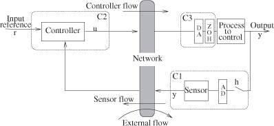
We consider the implementation represented in Figure 3.3. The network operates both (i) between computer 1 (C1) in association with the numerical information provided by the AD conversion (this computer includes a task that we call the sensor task and which generates the sensor flow) and computer 2 (C2) where we have the reference and the controller (in C2 we have a task called controller task which generates the controller flow), (ii) and between C2 and computer 3 (C3) which provides numerical information to the DA conversion in front of the zero-order hold (ZOH) which is connected to the actuator acting on the process to control.
The sensor flow which goes from the sensor to the controller will be noted as fsc. The controller flow which goes from the controller to the actuator will be noted as fca. The task which generates the sensor flow is time-triggered (the sampling is based on a clock), whereas the task which generates the controller flow is event triggered (the controller waits for sensor sample reception before computing and generating its flow).
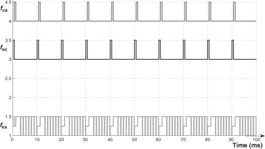
Generally, a network is not dedicated to only one application but shared between different applications. In order to make a general study of the process control application, when it is implemented through a network, we have to see, in particular, the influence of the flows of the other applications. It is why we have in Figure 3.3 what we call the external flow, noted as fex, which globally represents an abstraction of the flows of all the other applications. We also consider that this flow is periodic.
3.2.1.3.2. Choice of the sampling period
This choice is a basic action. The sampling period has, from the control point of view, an upper bound [JUR 58]. But from the network point of view a value that is too small gives a load that is too great. So, the choice results from a compromise. The relation ![]() , which has been given in [ÅST 97], is generally used. We consider here the bound
, which has been given in [ÅST 97], is generally used. We consider here the bound ![]() . As tr ≈ 40 ms; we have h = 10 ms. The controller is discretized with this sampling period; the measured dynamic characteristics are an overshoot less than 5%, a rise time
. As tr ≈ 40 ms; we have h = 10 ms. The controller is discretized with this sampling period; the measured dynamic characteristics are an overshoot less than 5%, a rise time ![]() and a response time
and a response time ![]() ms. These characteristics will be our references to analyze the performances of the control application through the studied networks.
ms. These characteristics will be our references to analyze the performances of the control application through the studied networks.
3.2.1.3.3. Considering the network CAN
As we want to emphasize message scheduling, we consider a CAN network limited to the MAC layer. The MAC layer determines the schedule for sending the frames of the controller, sensor flows, and external flows. For this study, we then have to specify the bit rate in the physical layer (we consider a bit rate of 125 Kbits s−1) as well as the frame transmission rate requested by the MAC layer (that we call the use request factor (URF) and which represents the load imposed on the network by the applications).
By calling Dsc, Dca, and Dex the duration of the sensor flow frames, the controller flow frames, and the external flow frames, respectively, h the sampling period of the process control application (the period for the controller and sensor flow), and Tex the period of the external flow, we have ![]() .
.
Concerning the numerical values, we consider that the frames of the controller flow and of the sensor flow have a length of 10 bytes, thus a duration of 640 μs. The frame of the external flow has a length of 16 bytes, thus a duration of 1,024 μs.
The component ![]() of the URF, which concerns the process control application and which represents the network capacity used by this application, has the value 12.8%. The use by the external frame of the network capacity will depend on its period Tex. It is this parameter that we will vary during our study in order to analyze the robustness of the scheduling of the process control application frames. The frame scheduling in the MAC layer of CAN [BOS 91; CIA 02] is based on priorities (static priorities) which appear in the identifier field (ID field) of the frames. The scheduling is done by comparing the field ID bit by bit (we start from the most significant bit, MSB). In CAN, the bit 0 is a dominant bit, and the bit 1 is a recessive bit. The lower the numerical value of the CAN ID, the higher the priority. We consider here the standard length of 11 bits for the ID field.
of the URF, which concerns the process control application and which represents the network capacity used by this application, has the value 12.8%. The use by the external frame of the network capacity will depend on its period Tex. It is this parameter that we will vary during our study in order to analyze the robustness of the scheduling of the process control application frames. The frame scheduling in the MAC layer of CAN [BOS 91; CIA 02] is based on priorities (static priorities) which appear in the identifier field (ID field) of the frames. The scheduling is done by comparing the field ID bit by bit (we start from the most significant bit, MSB). In CAN, the bit 0 is a dominant bit, and the bit 1 is a recessive bit. The lower the numerical value of the CAN ID, the higher the priority. We consider here the standard length of 11 bits for the ID field.
3.2.1.4. Evaluation of the influence of the network on the behavior of the process control application
This work has been done by using the tool TrueTime [CER 03; OHL 07], a toolbox for simulating distributed real-time control systems.
3.2.1.4.1. Dedicated network CAN
This study shows the influence of the format of the serial frames on the process control application. The evaluator J, applied to the regulation application when it is implemented through the network CAN without the external flow (thus the network CAN is dedicated to the regulation application), gives a cost J of 2.565 × 10⁻⁴. This value of J is called J0. The value J0 is very close to the value obtained without the network (see 3.2.1.2). The value J0 will be considered as the reference value to evaluate the performance of the regulation application, taking into account the influence of the external flow.
In the condition of J0, the time response to a unity input step has the following characteristics: overshoot D% = 5% and damping ζ = 0.7, response time about 45 ms. We can see that, with respect to the performance of the sampled process control application (section 3.2.1.3.2), the network has a very weak influence here. This is because the duration of each frame (640 μs) is very small with respect to the sampling period (10 ms).
3.2.1.4.2. Shared network CAN: considering static priorities and showing their inadequacy
We got the following important results from previous studies [JUA 05]:
– The priority associated with the controller flow (Pca) must be higher than the priority associated with the sensor flow (Psc); this way, we get the best performances for the control application (the intuition is that the controller has to send its message as soon as it receives the messages of the sensor).
URF(%) |
J |
|
|---|---|---|
30 |
2.773 × 10⁻⁴ |
8.11% |
80 |
3.281 × 10⁻⁴ |
27.9% |
90 |
3.915 × 10⁻⁴ |
52.6% |
99 |
7.370 × 10⁻⁴ |
187.0% |
100 |
1, 445 × 10−3 |
463% |
– If the priority of the external flow (Pex) is larger than Pca, and if the use request factor of the external flow (URFex) becomes very high, the external flow will use (as it has the largest priority) the network (bus) more and more often and will prevent the flows of the process control application from using the bus. (Consequently, the process control application will have bad performances and thus cannot be implemented.)
Table 3.1 gives the results obtained by using fixed priorities with Psc < Pca < Pex. By considering increases of the global URF – first column – (from 30% to 100%) due to increase of URFex (which increases from (30%–12.8%) to (100%–12.8%)), this table gives the evolution of the cost function J and the percentage of its variation with respect to ![]() .
.
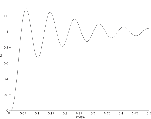
We have a degradation which increases with URF (when URF becomes too great we have a delay with a big jitter and making the performances so bad that we cannot implement the regulation application). The time response to a unity input step (when URF = 100%) is represented in Figure 3.4. We now have an overshoot of D = 29%. The response time here is very long compared to the response time when there is no implementation through the network (100 ms), see section 3.2.1.1. These are the results which have prompted the work on the hybrid priorities.
3.2.1.5. Idea of hybrid priority schemes: general considerations
When we have static priorities, as we have seen in the previous example, when the loads are high, and if the flows of the process control application do not have the highest priority, we cannot get acceptable control performances. However, in general, it is not always possible to give the highest priority to a process control application: we can have more important applications and, furthermore, if we have at least two process control applications, one will obviously not have the highest priority.
The idea of hybrid priority results from this problem, as previously stated, and also from the following important observation: in the general case of a distributed system, we have a lot of applications which generate different classes of flows which have different needs in terms of transmission urgency (constant urgency or variable urgency (from weak to strong)). A class is a characterization a priori, and thus, specified off-line. A class is a set of flows.
The needs are an operational characteristic which depend on the behavior of the application concerned. The needs are specified off-line, if they are constant, and online if they are variable. In the latter case, we say they are “dynamic needs”.
A process control application generates a class of two flows (controller flow and sensor flow) which have dynamic needs: strong urgency in a transient behavior after an input reference change (in order to follow the change) or after a disturbance (in order to make the regulation); small urgency in the permanent behavior.
3.2.1.5.1. The identifier (ID) field and the scheduling execution
The identifier field of a frame is divided into two levels (Figure 3.5): the first level represents the priority of a flow (it is a static priority specified off-line); the second level represents the priority of the transmission urgency (the urgency can be either constant or variable). The idea of structuring of the ID is present in the Mixed Traffic Scheduler [ZUB 97], [ZUB 00] which combines EDF (dynamic field) and FP (static field). In [WAL 01], the authors propose encoding the weighted absolute value of the error in the dynamic field (this idea is also presented in [MAR 04]) and to resolve the collisions with the least significant bits (static field).
A constant transmission urgency is characterized by a static priority (one m bit combination) specified off-line. A variable transmission urgency is characterized by a dynamic priority (which can take, generally speaking, m bit combinations among a subset of the m bit combinations).
The frames of the flows fsc and fca of a process control application have variable needs (strong urgency in a transient behavior after an input reference change (in order to follow the change quickly) or after a disturbance (in order to make the regulation quickly); weak urgency in a permanent behavior). That is why, in this study, we consider that the dynamic priority of the frames of the flows fsc and fca of a process control application can take any m bit combination of the set of m bit combinations. The scheduling is executed by, first, comparing the second level (needs predominance), and, secondly, if the needs are identical, by comparing the first level (flow predominance).
3.2.1.5.2. Cohabitation of flows with constant needs and flows of process control applications (variable needs)
We have the objective of good performances for the process control applications in transient behavior. This means that the urgent needs of these flows can be satisfied very quickly. For that, we impose a maximum value to the flows with constant needs for the priority of these needs (concept of priority threshold (Pr_th) for the constant needs). In this way, a strong transmission urgency of a process control application flow (dynamic priority with a very high value i.e. higher than Pr_th) will be scheduled first.
3.2.1.5.3. Toward making dynamic priorities
The concept of the dynamic priorities requires specifying, at first, the characteristic of a process control application which gives information on the needs, and, secondly, how these needs can be translated into a dynamic priority (computation of a dynamic priority, instants of re-evaluation of a dynamic priority). We propose to express the needs with a signal which aptly characterizes the behavior of a process control application: it is the control signal u.
3.2.2. Three hybrid priority schemes
We have defined three schemes. The first is what we call the strict hybrid priority (hp) scheme (computation of the dynamic priority directly from a function of the control signal u; re-evaluation after each sampling instant). The second is the hp scheme extended with a static time strategy (STS) for the re-evaluation of the dynamic priority (re-evaluation not always after each sampling time). This scheme is noted hp+sts. The third is a scheme which does not compute the dynamic priority directly from the control signal u (definition of a timed dynamic priority reference profile and trip in this profile by means of an on-line temporal supervision based on a function of the control signal u). The dynamic priority is re-evaluated after each sampling instant. This third scheme, which implements a dynamic time strategy for the trip in the timed dynamic reference profile, is noted as hp+dts.
We will now detail these three schemes.
3.2.2.1. hp scheme
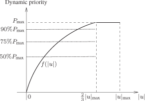
The needs are translated into a dynamic priority by considering an increasing function of |u| (call it f(|u|)) characterized by a saturation for a value of |u| less than the maximum of |u| (noted |u|max). We do not want the dynamic priority to take its highest value only when |u| is at its maximum but already for values before the maximum, in order to react quickly as soon as the needs begin to become important. So we decide (it is an arbitrary choice) to take ![]() as the value of |u| where the dynamic priority reaches its highest value.
as the value of |u| where the dynamic priority reaches its highest value.
Several functions f(|u|) have been studied [JUA 07b]. For this work, we consider the function f(|u|) represented in Figure 3.6. This function is defined by
![]()
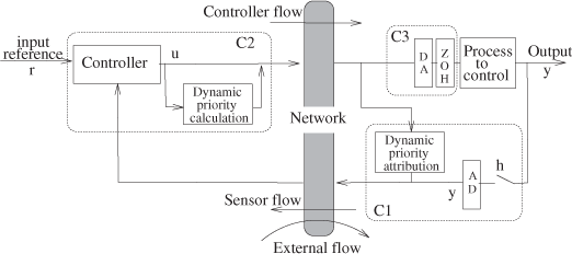
The computation of the dynamic priority is done by the controller each time it receives a frame that the sensor sends after each sampling instant (dynamic priority re-evaluated after each sampling instant). Then, after the reception of a frame from the sensor, the controller sends a frame with the value of the new dynamic priority. This frame reaches all the sites (CAN is a bus) and as the sensor site knows the first level of the ID of fca (it is a constraint for our implementation), it will learn the dynamic priority that it will put in the next frame that it will send (the dynamic priority is then used by the two flows of a process control application). The implementation of the dynamic priority mechanism (calculation by the controller task and attribution by the sensor task) is represented in Figure 3.7.
Taking into account the task implementation (sensor task is time-triggered, controller task is event-triggered), note that it is the sensor task which transmits the first frame at the start of the application. For this first frame, the sensor site has no information about the dynamic priority and, thus, we consider that it uses the maximum priority. This way, the first fsc frame reaches the controller site as quickly as possible.
3.2.2.2. (hp+sts) scheme
A criticism of the hp scheme is that we can have oscillatory behavior of the dynamic priority values (resulting from a damped sinusoidal transient behavior of u).
We can have, for example, this scenario for the dynamic priority values at three successive re-evaluation instants [JUA 07a]: the highest value at the first re-evaluation instant, then an intermediary value at the second, and again the highest value at the third re-evaluation instant, etc. Such an oscillatory behavior shows that the control of a situation requiring a big value of the dynamic priority is inadequate in terms of the maintenance of this big value, since after leaving this value for an intermediary one, at the second re-evaluation instant, we come back to this big value at the third re-evaluation instant. The observation of this phenomenon suggests increasing the duration of the dynamic priority with a big value in order to improve transient behavior.
The (hp+sts) scheme is then the following. In contrast to the scheme hp, where the dynamic priority is re-evaluated in the controller site after each reception of an fsc frame, the instant of the re-evaluation is no longer so closely related to the sampling instants. Here, the duration of the time interval between two successive re-evaluations depends on the value of the dynamic priority at the beginning of the time interval. This duration must be relevant, in particular, from the point of view of the transfer function of the process control application and, more precisely, of its transient behavior (defined before its implementation through the network). We considered the following algorithm:
– if the dynamic priority has a value between the highest priority (Pmax) and half the highest priority ![]() , we keep this value for four sampling intervals, and we re-evaluate the dynamic priority afterwards; this duration is equal to the rise time tr (we have chosen
, we keep this value for four sampling intervals, and we re-evaluate the dynamic priority afterwards; this duration is equal to the rise time tr (we have chosen ![]() ) which represents a good characteristic of a transient behavior).
) which represents a good characteristic of a transient behavior).
– if the dynamic priority has a value inferior to half the highest priority, we re-evaluate it after each sampling instant, as in the previous algorithm.
Note that the implementation of the dynamic priority is like the one represented in Figure 3.7 except that now we have a comparison with the priority ![]() and the new re-evalution strategy in the controller site.
and the new re-evalution strategy in the controller site.
3.2.2.3. (hp+dts) scheme
A criticism of the (hp+sts) scheme is the static aspect of the time strategy for re-evaluating the dynamic priority. The goal of this new scheme is to have a behavior which is flexible enough to adapt to different transient situations.
3.2.2.3.1. Main ideas
Fist, we define [JUA 08], which we call the reference profile of the dynamic priorities. This reference profile expresses the dynamic priority values, which must be used at the successive sampling instants of a transient situation (i.e. after an input change or a disturbance or after successive input changes and/or disturbances) from the beginning of such a situation till the establishment of the permanent behavior. This expression is made in function of a time domain which is a virtual view of the sampling process during a transient behavior.
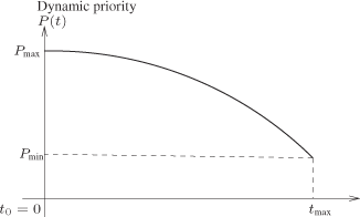
The reference profile that we are considering (Figure 3.8) consists of a decreasing continuously function P(t):
![]()
The values of P(t) decreases from a priority at time 0 (maximum dynamic priority at the beginning of the hardest transient situation) to a priority Pmin (this priority is used in three situations: at the end of a transient behavior, during a permanent behavior and at the configuration of the system) at time tmax. This time value must be compatible with the dynamic of the process control application; here we consider that tmax is the response time at 5% of the process control application (it is an arbitrary choice). When we are in permanent behavior (point Pmin, tmax), as soon as we have a transient situation (input change or disturbance), we have a movement on the left of the curve P(t) (if it is a very significant transition situation, we go to (point Pmax, 0)).
The dynamic priority decreases slowly from the value Pmax at the beginning of a transient behavior (in order to be as reactive as possible). Note that different functions of P(t) can be studied.
The time domain (0 ≤ t ≤ tmax) does not express the ordered sampling instants, but it allows for situating each virtual sampling instant tk with respect to the previous virtual sampling instant tk–1, and then to deduce the dynamic priority P(tk).
Initially, just after the appearance of an input change or a disturbance (movement to the left on the curve i.e. dynamic priority increase), we could think that we then only have movements showing a decrease in dynamic priority, but this is not a correct interpretation. What we have results from the influence of the network (variable loads) and also the possibility of successive fast input changes or disturbances in the application which lengthen the transient behavior. Thus, since the evolution of the dynamic priorities cannot be continually decreasing i.e. being at a virtual sampling instant, we can, by considering the reference profile curve, move back to a dynamic priority value higher than the present value. The evolution of the dynamic priorities between two successive virtual sampling instants can then be as is shown in Figure 3.2.
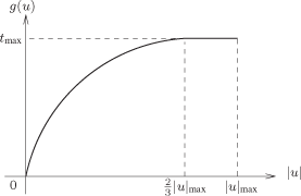
So, in order to take into account this behavior when computing the virtual sampling instants, we have to add a component called on-line temporal supervision, in addition to the sampling period h. This on-line temporal supervision is based on a function of the control signal (g(u)) which will correct the positioning of the virtual sampling instant.
We use (Figure 3.9) the function g(u) here with g(u) ∈ [0, tmax]:
![]()
3.2.2.3.2. Algorithm for computing the dynamic priority at any sampling instant tk
(tk ∈ [0, tmax]) The operations of the algorithm consist in positioning, when the controller receives the fsc frame, at an instant in the interval of time [0, tmax] of the definition of the reference profile and in detecting the value of the dynamic priority to use from this instant. The value of the instant depends on the value of g(u) at the reception of the fsc frames.
Initially (configuration of the system), the reference profile is at (point (Pmin, tmax)) i.e. tk = tmax. Then, upon the reception of an fsc frame, the controller:
1) computes g(u);
2) computes x = tk – αg(u), where x is an intermediate variable, α is a coefficient, defined by ![]() which balances the influence of g(u) by increasing this influence even more because the dynamic priority is low (when the dynamic priority is low, a large value of g(u) must induce greater feedback; it is not as necessary when the priority is already high)
which balances the influence of g(u) by increasing this influence even more because the dynamic priority is low (when the dynamic priority is low, a large value of g(u) must induce greater feedback; it is not as necessary when the priority is already high)
- if x ≤ 0 then x = 0; we go to the time 0 on the reference profile (priority Pmax),
- if 0 ≤ x ≤ tmax, we go to the time x in the reference profile and get the priority P(x);
3) re-initializes the virtual time for the next sampling tk = x + h (if tk > tmax then tk = tmax). This value will be used for computing the dynamic priority on the reception of the next fsc frame.
3.2.3. Study of the three schemes based on hybrid priorities
3.2.3.1. Study conditions
We consider the process control application which was presented in section 3.2.1.1. The input is a position step which starts at time 0, and we study the transient behavior until it reaches permanent behavior.
The QoS parameters, which need to be taken into consideration, are the mean delay D of the control loop and its standard deviation σ. The QoC parameter is the response time at 5% (noted res_t) which is obtained directly from the tool TrueTime.
In order to evaluate the QoS parameters, we use the message exchange temporal diagrams which are also provided by TrueTime, and the value of res_t.
From the message exchange temporal diagrams, we can get the delay in the control loop (delay of the message of the flow fsc + delay of the message of the flow fca + Dsc + Dca) for each sampling period (call Di this delay for the sampling period i).
| URF (%) |
Multiple of |
Tex (ms) |
|---|---|---|
99.2 |
9 |
1.1111 |
89.6 |
8 |
1.25 |
80 |
7 |
1.4286 |
70.4 |
6 |
1.6667 |
60.8 |
5 |
2.0 |
51.2 |
4 |
2.5 |
41.6 |
3 |
3.3333 |
32 |
2 |
5.0 |
22.4 |
1 |
10.0 |
Counting the number n of sampling periods in the response time res_t, we deduce the value of ![]() and σ by the formulas:
and σ by the formulas: ![]() .
.
In order to make a quantitative analysis, we cause a variation in the network load (URF) by varying the period Tex of the external flow: we consider an external flow, the frequency of which (noted ![]() ) is a multiple of the sampling frequency
) is a multiple of the sampling frequency ![]() . The different URFs being considered are given in Table 3.3.
. The different URFs being considered are given in Table 3.3.
The following important points must still be emphasized:
– the flows fsc (which are generated at the sampling times) and fex are synchronous (starting at the same time) and as we consider the cases where the frequency of fex is a multiple of the sampling frequency, then their medium access attempts coincide at every sampling time;
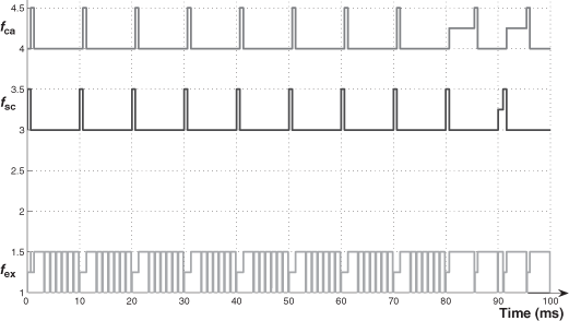
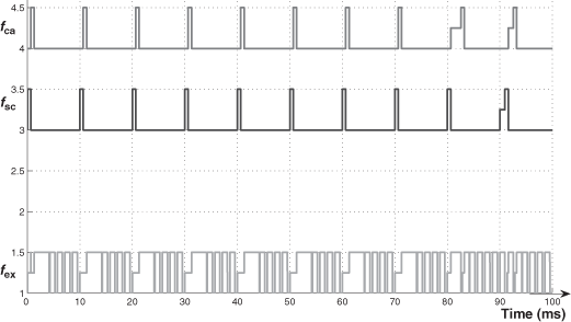
– up to the value 70.4% of the URF (value of 1.6667 ms for Tex), we can see that during Tex, one frame of each flow can access the medium: 0.96 ms + 0.64 ms = 1.6 ms < 1.6667 ms (the third flow can begin to be transferred and then cannot be interrupted). This remark is very important for the analysis which is done in section 3.2.3.3;
– a last point must be still noted: at the beginning of a transient behavior, as the control signal is at a maximum, the dynamic priority of the flows of the process control application is Pmax. This point also is important for the analysis in sections 3.2.3.2, 3.2.3.3, and 3.2.3.4.
3.2.3.2. hp scheme
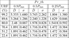
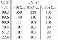
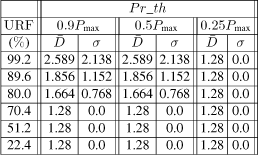
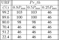
As concerns the process control application, we give ![]() and σ in Table 3.4 and res_t in Table 3.5. The values depend on the network load URF (which depends on the frequency fex), and on the priority threshold Pr_th (which depends on the importance we give to fex).
and σ in Table 3.4 and res_t in Table 3.5. The values depend on the network load URF (which depends on the frequency fex), and on the priority threshold Pr_th (which depends on the importance we give to fex).
Concerning the values of ![]() , we observe the following main points:
, we observe the following main points:
– for each value of Pr_th:
- for URF ≤ 70.4 %, we note that we have the same values of ![]() and σ whatever the value of URF is. This is a consequence of the fact that (cf. remark in the study condition) the two frames of fsc and fca, during each sampling period, can be sent during the period of fex, which is not the case with URF > 70.4 % where
and σ whatever the value of URF is. This is a consequence of the fact that (cf. remark in the study condition) the two frames of fsc and fca, during each sampling period, can be sent during the period of fex, which is not the case with URF > 70.4 % where ![]() and σ increase with the value of URF (see in table 3.4,URF = 80 %, 89.6 %, 99.2 %).
and σ increase with the value of URF (see in table 3.4,URF = 80 %, 89.6 %, 99.2 %).
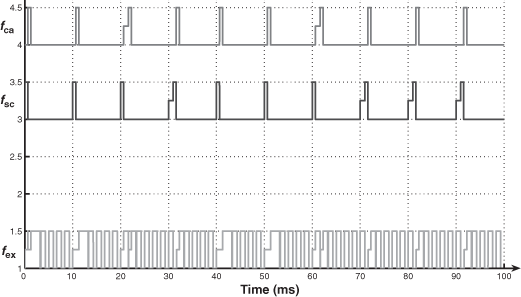
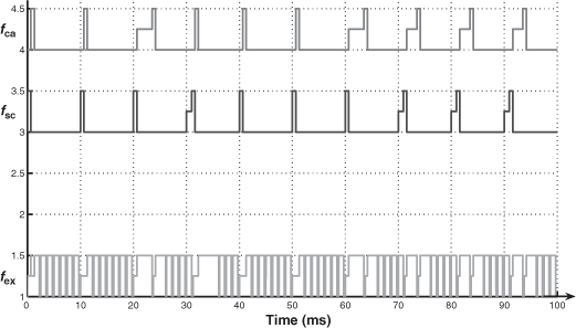
- We explain the difference (URF ≤ 70.4 % and URF > 70.4 %) by means of two exchange temporal diagrams provided by TrueTime (Figures 3.10 and 3.11 for the case of Pr_th = 0.9Pmax). In Figure 3.10, we see that the frames fsc or fca can be delayed, during a sampling period, at the very most for the duration of one frame of fex (0.96 ms). In Figure 3.11, we see that the two frames of fsc and fca can be delayed, and the delays for the frame of fca can be more than the duration of one frame of fex.
- Note then, when URF > 70.4% and for increasing values of URF, ![]() increases because the network load increases (then more chances to delay the frames of fsc and fca).
increases because the network load increases (then more chances to delay the frames of fsc and fca).
– For increasing values of Pr_th, ![]() also increases because the dynamic priorities of the frames of fsc and fca have fewer chances of being higher (except at the beginning of a transient behavior) than the threshold.
also increases because the dynamic priorities of the frames of fsc and fca have fewer chances of being higher (except at the beginning of a transient behavior) than the threshold.
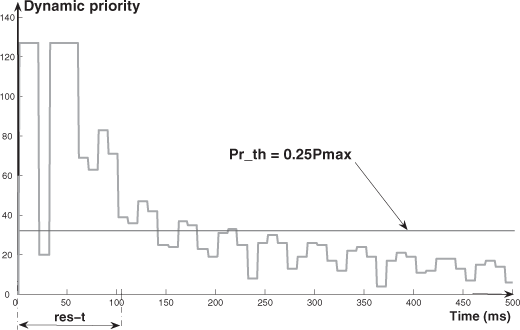
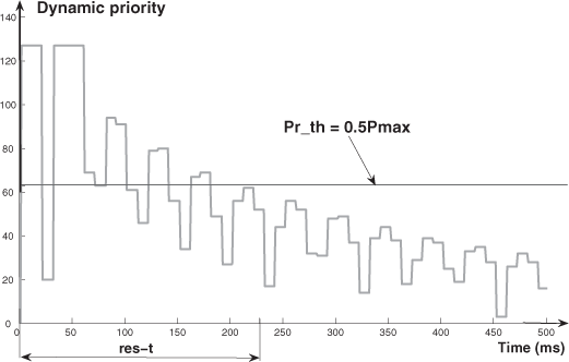
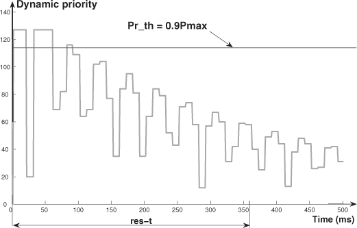
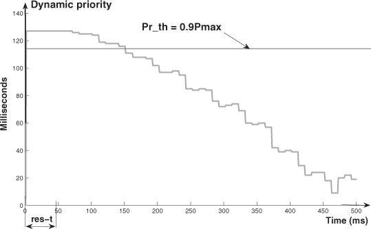
– Concerning the values of σ, we have the following comments: for each value of URF, the variation of σ, when Pr_th increases, presents a maximum (which occurs for a value of Pr_th around Pr_th = 0.5Pmax). The explanation is given by means of Figures 3.12–3.14 (which represent the dynamic priority variation for Pr_th = 0.25Pmax, Pr_th = 0.5Pmax, and Pr_th = 0.9Pmax). These figures allow us to evaluate the number of times where, during the res_t, the frames of fca have a higher or lower priority than the threshold (a higher priority means a lower delay; a lower priority means a bigger delay). Then we can see that we have for Pr_th = 0.5Pmax, the maximum value of σ (the number of times where the dynamic priorities are higher than the threshold ≈ the number of times where the dynamic priorities are lower than the threshold). For Pr_th = 0.25Pmax (Pr_th = 0.9Pmax), the number of times where the dynamic priorities are higher (lower) than the threshold is much greater than the number of times where the dynamic priorities are lower (higher) than the threshold. Thus, we have values of σ smaller than with Pr_th = 0.5Pmax (in the case of Pr_th = 0.25Pmax with a small value of ![]() ; in the case of Pr_th = 0.9Pmax with a higher value of
; in the case of Pr_th = 0.9Pmax with a higher value of ![]() ).
).
Obviously, for each value of Pr_th, σ increases with URF (the reason is still the increase of the network load).
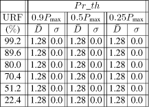
Important remark: for Pr_th ≤ 0.15Pmax i.e. low threshold (we have not represented the results for reasons of limited space), we have the minimal value for ![]() (1.28 ms i.e. a frame of fsc (0.64 ms) and then a frame of fca (0.64 ms) always use the medium before the frames of fex because the dynamic priority is always higher than Pr_th during the response time). Then, of course, σ = 0.
(1.28 ms i.e. a frame of fsc (0.64 ms) and then a frame of fca (0.64 ms) always use the medium before the frames of fex because the dynamic priority is always higher than Pr_th during the response time). Then, of course, σ = 0.
3.2.3.3. (hp+sts) scheme
For the hp scheme, we give ![]() and σ in Table 3.6 and res_t in Table 3.7. The values are obviously a function of URF and Pr_th.
and σ in Table 3.6 and res_t in Table 3.7. The values are obviously a function of URF and Pr_th.
We can see important differences with the hp scheme:
– for URF ≤ 70.4 %, ![]() is now always constant, whatever the Pr_th is (this is for two reasons: the first reason is because of the consequence of the property (URF ≤ 70.4 %) indicated in section 3.2.3.1; the second is the fact that now, at the beginning of the transient behavior, the dynamic priority is used by the flows fsc and fca for a duration, at least, equal to 4h). Obviously, as
is now always constant, whatever the Pr_th is (this is for two reasons: the first reason is because of the consequence of the property (URF ≤ 70.4 %) indicated in section 3.2.3.1; the second is the fact that now, at the beginning of the transient behavior, the dynamic priority is used by the flows fsc and fca for a duration, at least, equal to 4h). Obviously, as ![]() is constant, σ = 0.
is constant, σ = 0.
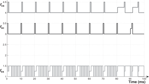
– For Pr_th = 0.25Pmax, we have ![]() which is constant for all URF values (this means that, on all the network load conditions, the dynamic priority is higher than the threshold). The explanation is given by the exchange temporal diagram on Figure 3.15.
which is constant for all URF values (this means that, on all the network load conditions, the dynamic priority is higher than the threshold). The explanation is given by the exchange temporal diagram on Figure 3.15.
– Analysis of a row of Table 3.6 (in the case where Pr_th > 0.25Pmax): we have the same values of ![]() and σ whatever the value of Pr_th. The explanation is given by the exchange temporal diagrams of Figures 3.16 and 3.18 where we consider URF = 99.2 %. These diagrams are identical.
and σ whatever the value of Pr_th. The explanation is given by the exchange temporal diagrams of Figures 3.16 and 3.18 where we consider URF = 99.2 %. These diagrams are identical.
– Analysis of a column of Table 3.6 (in the case where URF > 70.4 %): we note an increase of ![]() and σ with URF (the explanation is given by Figures 3.17 and 3.18); the delay of the frame fca (sampling periods 8 and 9) in Figure 3.18 is higher than in Figure 3.17).
and σ with URF (the explanation is given by Figures 3.17 and 3.18); the delay of the frame fca (sampling periods 8 and 9) in Figure 3.18 is higher than in Figure 3.17).
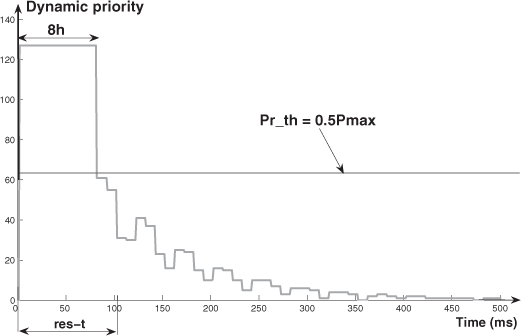
With respect to the hp scheme, all the improvements (which give best response time for the process control application) result from the fact that the dynamic priority Pmax is used for a longer time. In Figure 3.19 (compare with Figure 3.13), we have an example of the evolution of the dynamic priority (we have Pmax during 8h).
3.2.3.4. (hp+dts) scheme
We give, as for the previous schemes, ![]() and σ in Table 3.8 and res_t in Table 3.9.
and σ in Table 3.8 and res_t in Table 3.9.
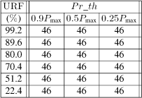
We can see now that we always have the minimum constant value ![]() (duration of the fsc frame (0.64 ms) + duration of the fca frame (0.64 ms)), then σ = 0, and the best response time (46 ms). This is a consequence of the fact that the dynamic priority is continuously controlled (by the control signal u) and that it is higher than the threshold for a time longer than the res_t (see Figure 3.20).
(duration of the fsc frame (0.64 ms) + duration of the fca frame (0.64 ms)), then σ = 0, and the best response time (46 ms). This is a consequence of the fact that the dynamic priority is continuously controlled (by the control signal u) and that it is higher than the threshold for a time longer than the res_t (see Figure 3.20).
3.2.4. QoC visualization
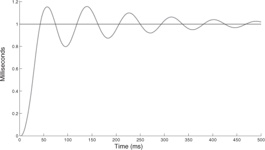
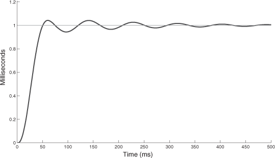
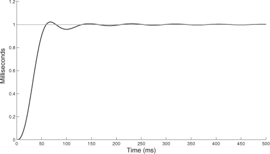
We represent, in Figures 3.21–3.23, the time response to an input step for the three schemes in the following conditions: URF = 99.2% and Pr_th = 0.9Pmax. The oscillatory transient behavior clearly shows the performances of the three schemes in terms of overshoot and damping. The conditions of a big network load and a high threshold still show the interest of the two schemes with a time strategy (hp+sts, hp+dts) to get good performances. The dynamic aspect of the time strategy in the scheme hp+dts shows in the end that it is the best scheme.
3.2.5. Comment
We have considered three hybrid priority schemes and we have demonstrated the particular interest of a scheme, call (hp+dts), with a double aspect: dynamic priority based on a temporal supervision function of the control signal of the process control application. We have also evaluated, on the one hand, the QoS in terms of the mean delay and its standard deviation, and, on the other hand, the QoC in terms of the response time at 5%, and the relation between QoS and QoC (overshoot, damping). Concerning the results which have been obtained, we want to emphasize that, even with a big extended load (consider Figures 3.21–3.23, with URF = 99% whereas the load of the process control application is only 12.8%), the process control application gets very good results (especially with the last two schemes).
3.3. Bandwidth allocation control for switched Ethernet networks
Compared to the CAN bus protocol studied in section 3.2, the native Ethernet does not implement any priority mechanism. Non-standardized solutions have been proposed: adapting the inter-frame gap (smaller for high priority frames), modifying the Binary Exponential Backoff algorithm (the waiting time is not randomly calculated, but in relation with the priority), or using a variable length of the preamble (smaller for high priorities). Another approach consists of using a time division multiple access method over the native CSMA/CD protocol: pre-allocated time slots are defined for the transmission of time-critical data.
Nevertheless, the evolution of Ethernet to segmented architectures and the definition of the Virtual Local Area Networks (VLAN) have led to the birth of a new standards set (802.1D/p, 802.1Q) in which new encapsulation fields are added to the classical frame [IEE 03]. One of these fields is specified in order to support eight priority levels associated with eight types of applications (voice, video, network management, best effort, etc.). The number of classes of service may be different to the number of priority levels, and also different for each port. That is why the standard also recommends a mapping between classes, priority, and ports queues.
The next point is the scheduling policy used to forward the frames at the output port regarding their dedicated priorities. [IEE 03, section 8.6.6] defines two items:
– for a given supported value of traffic class, frames are selected from the corresponding queue for transmission only if all queues corresponding to numerically higher values of traffic class supported by the port are empty at the time of selection;
– for a given queue, the order of which frames are selected shall maintain the incoming ordering.
It means that the scheduling policy defined is the Strict Priority (SP) algorithm, and the policy must be FIFO for a given queue. But the standard enables to implement other algorithms. The main drawback of the SP algorithm is that it can lead to the impossibility for the lowest priority queues to be served. It corresponds to famine situations for the non-real-time applications. To resolve it, CoS switches implement a supplementary policy: the Weighted Fair Queuing (WFQ). In the fair queuing algorithms, the service offered to the high priority queues is moderated as follows. A weight is associated with each queue. Then the scheduler gives to each queue (from the highest priority to the lowest) a bandwidth determined by its associated weight.
The WFQ, initially proposed in [DEM 89], is also known as the packetized generalized processor sharing (PGPS). It is based on the conceptual algorithm called generalized processor sharing (GPS) [PAR 93]. However, practical implementations of WFQ in today’s switch products are based on its simplified version named WRR.
In a round robin policy, packets are pushed in queues according to their priority level. Then the server pools the different queues according to a cyclic sequence (using a pre-computed order defined by the queues priorities) in an attempt to serve one packet for each non-empty queue. Even if this algorithm respects the fairness quality, no flexibility is integrated. Moreover, the fairness can be damaged with variable packet lengths. To improve the lack of flexibility of a simple round robin policy, the WRR [DEM 89; KAT 91] associates a weight ωi with each flow i. Now, the WRR server will attempt to serve a flow i with a rate of ![]() before looking for the following queue. Comparing to PGPS, delays could be more important since if the system is heavily loaded and a frame just misses its slot, it will have to wait for its next slot i.e. a cycle.
before looking for the following queue. Comparing to PGPS, delays could be more important since if the system is heavily loaded and a frame just misses its slot, it will have to wait for its next slot i.e. a cycle.
In the following, a WFQ policy based on a per-priority queuing and a WRR scheduling is studied. This implementation is typical of switch products, like the Cisco Catalyst 2950. The WRR assigns a priority i to each flow. It serves all the flows in a cyclic way, from the queue with the highest priority to the lowest. The number of frames that will be forwarded by the server for a queue i is bounded by the number ωi. When the queue is empty, the scheduling protocol immediately processes the next queue.
In the context of NCS, the CoS is interesting since it enables to change the best effort service and the FIFO scheduling by a differentiated service and advanced scheduling. This approach is illustrated in Figure 3.24. For instance, the WRR policy [DEM 89] manages the network performances by adjusting the number of frames forwarded for each flow according to the frames priority. To illustrate the interest of CoS, a modification of the TrueTime kernel was proposed in [DIO 08] in order to allow the simulation of the WRR over switched Ethernet networks. It was then used to differentiate the service offered to the frames on the embedded network of the quadrotor.
The performances are by means of hard deadline computation algorithm which is treated in the following section.
3.3.1. NCS performance analysis
In this section, we analyze network-induced delay effects on system stability for linear, time-invariant control systems. The state space equations are modified according to induced delay, NTs, where N varies from 1 to D. Then DTs is the hard deadline which represents the critical value of induced delays beyond which the stability of the overall system is not guaranteed. The pole positions of the augmented state equation are tested to derive the necessary conditions for asymptotic system stability. [KAN 92]define the hard deadline as follows. Let XA and UA be the allowed state space and the admissible input space, respectively. Suppose the state, x, is evolved from time ko in the presence of a computation-time delay N according to
where Φ is the state transition map and u is the control signal. Then, the hard deadline is given by
Due to the delay in the transmission, it is assumed that the control input is updated at time mTs. The augmented state space equation becomes
The hard deadline is derived from equation 3.3 by iteratively testing the current pole location of the closed-loop-augmented system. In this case, the hard deadline is expressed in the number of sampling period.
3.3.2. NCS modeling
3.3.2.1. Introduction
PN is able to formally represent the behavior of any kind of system. It has the capability to express many mechanisms usually used in distributed environments such as parallelism, synchronization, concurrency, and resource sharing [DAV 04; JEN 92; JUA 04]. Moreover, there are many references in the literature where PN is employed to model network protocols in order to validate protocol specifications, as in [BIL 82] and [LAI 89]. The objective of this research is to show that PN can also be used to model NCS in order to assess its behavior in a common formal language.
NCS are complex to model since they integrate different components such as controllers, actuators, sensors, the plant, and the network. In order to simplify the NCS model, it is necessary to split it into several sub-models. This means that the PN used to model NCS has to be based on the concept of Hierarchy defined in Hierarchy PN (HPN). In this case, a transition of the PN model can represent a sub-PN model. This particular transition is named substitution transition. The advantage of using HPN is also to build models in modular way. For example, the change of protocols in the NCS model consists only in replacing the sub-model describing the current protocol by the new one. Another difficulty during the NCS modeling is to be able to differentiate the messages according to its time constraints. The solution is to use the Colored HPN (CHPN). In this case, the color allows message tagging in regard to its time specifications. Finally, the time properties are obviously defined in NCS modeling. Thus, the Timed CHPN (TCHPN) is chosen to model NCS. This is the formalism defined by [JEN 92] and implemented in CPNTools developed by the Aarhus University [JEN 07].
3.3.2.2. Network modeling
Network modeling is usually achieved in two steps: traffic modeling and network device modeling (router, switch, etc.). Traffic modeling has to define the frame format according to the kind of protocol used. This modeling can be simplified by specifying only the format size and the information that is useful in the NCS context. The following list of colors is used to represent a frame:

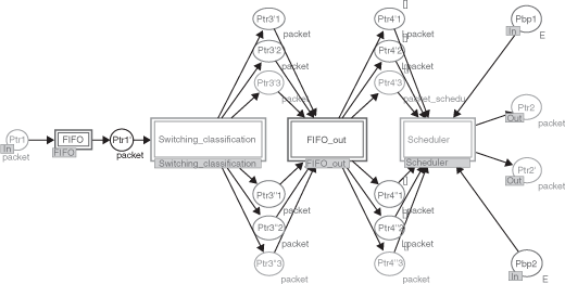
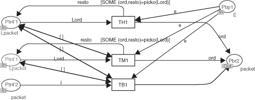
There are many ways to model a network device (ref ). Firstly, they all depend on memory allocation management but this memory can be located at the input, at the output or in the middle of the device. The last approach also called shared memory architecture is the one most often implemented by network constructors, and is the one retained in this paper. Secondly, the communication device can manage differentiated services. It requires defining at each output because there are as many buffers as specified differentiated services. This services integrate the used mechanisms to switch to the messages in the output buffer according to both their destination and their priority, and implement the scheduler. Thirdly, the wires have to be considered. The full-duplex mode is used to model a link. Figure 3.25 shows the general functions of a communication nodes, and Figure 3.26 shows its corresponding TCHPN model.
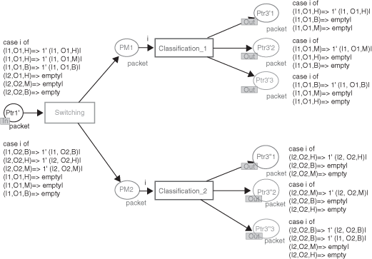
The switching modeling describes two functions in one:
– basic switching, which ensures frame transfer between the input port and the output port of the network device;
– and the switching between the different buffers associated with one output port, which is done through analyzing the priority level of the frame. This function is called the classification step.
Figure 3.27 shows a simplified TCHPN model of a network device including two output ports able to differentiate three service levels. This means that three buffers are defined per output port. The frames waiting inside the shared memory and extracted in the FIFO queue model are firstly sent to the appropriate output port and then they are sent to the buffer corresponding to the frame priority (high, medium, and low).
Finally, managing the frames stored in the output buffers depends on the selected scheduling policy. The constructors of network devices mainly implement two kinds of schedulers: strict priority policy and the WRR policy. The general rule applied to manage the output buffers in the strict priority mode is that the frames stored in a buffer are processed only if all the buffers with higher classes do not contain a frame. The advantage of the strict priority policy is its simplicity to model (Figure 3.28) and then to code in network devices. The problem is the generation of famine situation, because if the high class buffer continually receives frames, the frames waiting in the lower class buffers are not processed.
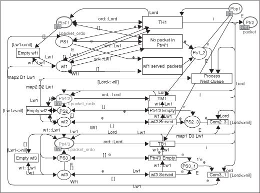
On the other hand, the WRR scheduler is more complex to model (Figure 3.29), but avoids the famine problem. The WRR scheduler cyclically the output buffers, and the number of frames processed is relative to the weight associated with each buffer. The weight of the high class buffer should be larger than the others in order to offer more bandwidth for the high priority frames. If a buffer is empty, the WRR scheduler automatically works on the following buffer, and so on.
The implementation of schedulers in the network devices is crucial in the context of NCS, since it allows for differentiating the services offered by the network according to the temporal constraints of the application. But, the difficulty is to analyze the relationships between the network tuning and controller specifications. The main interest of proposing an integrated approach for modeling NCS is to be able to study and to adjust the network parameters by observing their impacts on the plant’s behavior.
3.3.2.3. System modeling
The NCS structure discussed in this section is composed of the plant, sensors, controllers and actuators which are spatially distributed and closed over the network. It is supposed that a sensor is time-driven with an identical sampling period h. By event-triggered controller or actuator, it is meant that the calculation of the new control or actuator signal is started as soon as information concerning the new control arrives, similar to [HAL 88]. Suppose that an LTI dynamical discrete time model is described as follows:
where xk ∈ =ℜn is the state vector, yk (k) ∈ ℜm the output vector and uk ∈ =ℜp the input vector. Φ; Γ; C are all real constant matrices and matrix of appropriate dimensions.
The controller is defined by the following equation
![]()
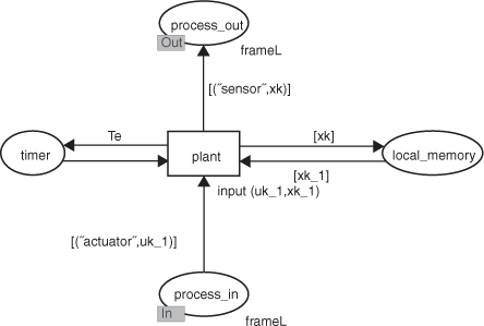
where K is the controller gain matrix to be designed. Each of the components involved in the NCS are assigned to a specific task which is structured in code segments. The model used to define the state space equation is represented in Figure 3.30. The functions process_ in and process_out corresponds to the actuator input and sensor output respectively. The current state value is computed at each sample time and stored in local memory when the code associated with the transition plant is executed.
In this chapter, only the controller is detailed. The other models (actuators, sensors, etc.) are explained in [BRA 07].
3.3.2.4. Controller modeling
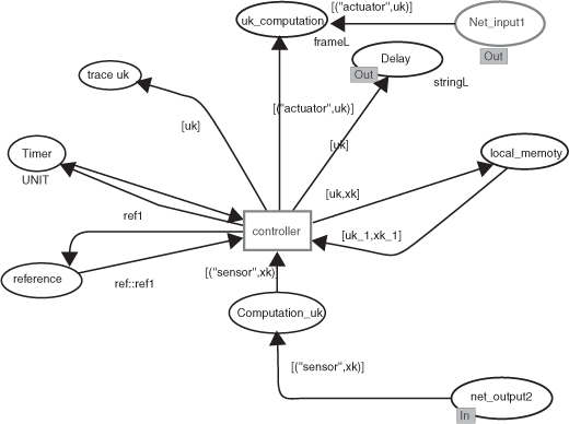
The model of the controller is shown at Figure 3.31. The node net_output2 receives the value xk from the sensor through the network. This value allows the transition controller to be sent on, then the associated segment code is executed as represented by the following commands.
input ( cons, uk_1, xk );
output (uk);
action
let
val convert_string_to_real =Option. valOf oReal. fromString;
val cons1= convert_string_to_real (cons);
val uk1_1= convert_string_to_real (uk_1);
val xk1=convert_string_to_real (xk);
val k1_1= convert_string_to_real (K1);
val uk1= k1_1*(cons1–xk1);
val uk=Real. toString (uk1);
in
uuk: =[uk];
uk
end ;
where parameter k1_1 is the control feedback gain and ref1 is the reference value. At this stage, the control or sensor signals have to be embedded in order to be transmitted through the network.
3.3.3. Network adaptation mechanism
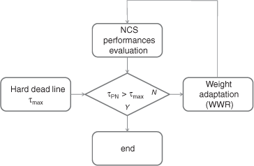
Figure 3.32 describes the global procedure for NCS analysis based on PN modeling. The maximum acceptable delay, τmax, is determined by means of the hard deadline algorithm. Then, τmax is compared to delay τ PN which is provided by the PN model. If necessary, the weights are re-assigned off-line.
3.3.4. Example
3.3.4.1. Maximum delay computation
Consider the discrete-time system:
![]()
Where K the state feedback matrix is determined in such a way so as to minimize the following cost function
![]()
Where Q ∈ ℜnxn and R ∈ ℜxl are positive semidefinite and positive definite, respectively. K is obtained by solving the associated discrete Riccati equation. For this example Q = 2 and R = 4. Then K = 0.402. The pole of the closed loop system is given by

is computed for different values of N. The system becomes unstable for N = 3. The sampling period is fixed at 1 ms. Then the maximum acceptable delay is τmax = 3 ms.
3.3.4.2. Results
The objective of this section is to show the interest of Petri Nets approach to simulate NCS. The system being considered is the same as the one before. Ethernet uses 10BT links. In these simulations, two kinds of traffic are considered. Real-time traffic between the controller and the sensors/actuators is periodically sent at Te and the size of the message correspond enough to the minimal Ethernet frame size to be able to transport the output and input information. The second type of traffic is called background traffic and is used to load the network. It is not time-constrained. This traffic allows for simulating the context of a shared network where the network can be used by other applications. The real time frames are tagged with a high priority field, and the background frames are tagged with a low priority field. The Ethernet switch implements the WRR scheduler and it is tuned to offer 10% of the total bandwidth to the real-time frames and 90% to the background traffic. This WRR configuration is called (A).
The first scenario generates background frames using 30% of the network bandwidth. Figure 3.33 a shows that this load does not disturbed the process system performances since the real-time traffic delays observed in Figure 3.33b are low (less than 0.5 ms).
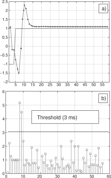
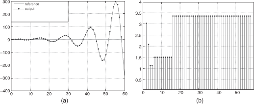
The second scenario increases the network load at 70% inducing progressively (due to the time to fill the buffers) a degradation on the real time frame delays (Figure 3.34b). The observed delays are up to 3 ms and generate instability on the process control.
The NCS modeling offers a double view in the same environment (Petri Nets), allowing designers to better understand the interactions between the process control and the network. In this case, the delays induced by the network have to be mitigated to ensure the stability of the system. Firstly, the hard-deadline method is used to estimate the delay threshold acceptable for the process controller. The result obtained that is the delay has to be lower than 3 ms. Secondly, the network parameters have to be tuned. Moreover, the weights of the WRR scheduler have to be changed in order to offer more bandwidth to real-time traffic. Secondly, the Petri net model is then run in an iterative way to find a “good” configuration. The solution called the WRR configuration (B) is to provide 99% of the bandwidth for the real-time traffic and only 1% for the background traffic. Finally, a simple algorithm (implementing in the Ethernet device) allows to dynamically switch between the (A) and (B) configurations according to the real-time frame delays. Figure 3.35 shows the results when this algorithm is applied. When a real-time frame delay is greater than 3 ms (Figure 3.35b), the configuration (B) is selected in order to reduce this delay and to maintain the stability of the system (Figure 3.35a).
Figure 3.33. WRR configuration (A) with an overload of 30%: (a) system output, (b) real-time frame delay in ms
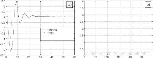
Figure 3.34. WRR configuration (A) with an overload of 70%: (a) system output, (b) real-time frame delay in ms
3.4. Conclusion
Two approaches for network resource adaptation have been presented in this chapter. The first part shows the interest of a hybrid priority strategy for message scheduling on a network. Two applications with different needs in terms of transmission urgency in their messages flows (one with variable transmission urgency for its messages; another with constant needs) are distributed through the network. An important characteristic in an NCS context is the capacity to implement process control applications with good performances, whatever the network load is. We have precisely shown that message scheduling strategies, based on hybrid priority schemes, allow for implementing a distributed process control application, even if the network load is heavy. NCS requires a global modeling of all its components in order to be able to precisely evaluate its performances. The second part of the chapter shows that the PN formal language can express the behavior of communications, controllers and plants. It allows for easily tuning the network parameters by directly analyzing their effects on the system to be controlled. Moreover, PN can be used to test new QoS adaptive algorithms embedded inside Ethernet switches by dynamically tracking the current QoC level. For both approaches, the network is adapted according to the performances of the applications, which are expressed in terms of stability.
3.5. Bibliography
[ÅST 97] ÅSTRÖM K., WITTENMARK B., Computer-Controlled Systems, Information and System Sciences Series, Prentice Hall, 3rd edition, 1997.
[BIL 82] BILLINGTON J., Specification of the Transport service using Numerical Petri Nets, Second International workshop specification, Testing and Verification, IFIP, West Lafayette, USA, October 1982.
[BOS 91] BOSCH, CAN specification 2.0 (A), www.semiconductors.bosch.de/pdf/can2-spec.pdf, 1991.
[BRA 07] BRAHIMI B., Integrated approach based on high level Petri nets to simulate and evaluate the networked control systems, PhD thesis, Henri Poincaré University Nancy I, France, 2007.
[CER 03] CERVIN A., HENRIKSSON D., LINCOLN B., EKER J., ÅRZÉN K.-E., How Does Control Timing Affect Performance? Analysis and Simulation of Timing Using Jitterbug and TrueTime, IEEE Control Systems Magazine, vol. 23, num. 3, p. 16–30, June 2003.
[CIA 02] CIA, CAN, CANopen, DeviceNet, URL www.CAN-CiA.de, 2002.
[DAV 04] DAVID R., ALLA H., Discrete, Continuous, and Hybrid Petri Nets, Springer-Verlag, Berlin, 2004.
[DEM 89] DEMERS A., KESHAV S., SHENKER S., Analysis and simulation of a fair queueing algorithm, ACM SIGCOMM Computer Communication Review, vol. 19, num. 4, p. 1–12, September 1989.
[DIO 08] DIOURI I., BERBRA C., GEORGES J.-P., GENTIL S., RONDEAU E., Evaluation of a Switched Ethernet network for the control of a quadrotor, 16th Mediterranean Conference on Control and Automation (MED’08), Ajaccio, France, p. 1112–1117, June 2008.
[HAL 88] HALEVI Y., RAY A., Integrated communication and control systems: Part I- Analysis, ASME Journal of Dynamic Systems, Measurement and Control, vol. 110, num. 4, p. 367–373, 1988.
[IEE 02] IEEE COMPUTER SOCIETY, IEEE standard for information technology – Telecommunications and information exchange between systems – Local and metropolitan area networks – Specific requirements – Part 3: Carrier sense multiple access with collision detection (CSMA/CD) access method and physical layer specifications, IEEE standard 802.3, Edition 2002, 2002.
[IEE 03] IEEE COMPUTER SOCIETY, IEEE Standards for local and metropolitan area networks – Virtual bridged local area networks, IEEE standard 802.1Q, Edition 2003, 2003.
[JEN 92] JENSEN K. (ed.), Application and Theory of Petri Nets, vol. 616 of Lecture Notes in Computer Science, Springer, 1992.
[JEN 07] JENSEN K., KRISTENSEN L., WELLS L., Coloured Petri Nets and CPN Tools for modelling and validation of concurrent systems, International Journal on Software Tools for Technology Transfer (STTT), vol. 9, num. 3, p. 213–254, June 2007.
[JUA 04] JUANOLE G., DIAZ M., VERNADAT F., Réseaux de Petri étendus et méthodologie pour l’analyse de performances, Report num. LAAS 03480, Laboratoire d’Analyse et d’Architecture des Systèmes, Toulouse, France, 2004.
[JUA 05] JUANOLE G., MOUNEY G., CALMETTES C., PECA M., Fundamental Considerations for Implementing Control Systems on a CAN Network, FET2005, 6th IFAC International conference on Fielbus Systems and their Applications, Puebla, Mexico, November 2005.
[JUA 07a] JUANOLE G., MOUNEY G., Networked Control Systems: Definition an Analysis of a Hybrid Priority Scheme for the Message Scheduling, Proceedings of the 13th IEEE conference on Embedded and Real-Time Computing Systems and Applications (RTCSA2007), Daegu, Korea, August 2007.
[JUA 07b] JUANOLE G., MOUNEY G., Using an hybrid traffic scheduling in networked control systems, Proceedings European Control Conference 2007, Kos, Greece, July 2007.
[JUA 08] JUANOLE G., MOUNEY G., CALMETTES C., On different priority schemes for the message scheduling in Networked Control Systems: Definition an Analysis of a Hybrid Priority Scheme for the Message Scheduling, Proceedings of the 16th Mediterranean Conference on Control and Automation, MED’08, Ajaccio, France, June 2008.
[JUR 58] JURY E. I., Sampled-Data Control Systems, Wiley, New York, 1958.
[KAN 92] KANG S., HAGBAE K., Derivation and Application of Hard Deadlines for RealTime Control Systems, IEEE Transaction On Systems, Man and Cybernetics, vol. 22, num. 6, p. 1403–1413, 1992.
[KAT 91] KATEVENIS M., SIDIROPOULOS C., COURCOUBETIS C., Weighted round-robin cell multiplexing in a general purpose ATM switch chip, IEEE Journal on Selected Areas in Communications, vol. 9, num. 8, p. 1265–1279, October 1991.
[LAI 89] LAI R., DILLON T.-S., PARKER K.-R., Application of numerical Petri nets to specify ISO FTAM Protocol, Singapore International Conference on Networks, Singapore, July 1989.
[MAR 04] MARTI P., YEPEZ J., VELASCO M., VILLA R., FUERTES J., Managing quality-of-control in network-based control systems by controller and message scheduling co-design, Industrial Electronics, IEEE Transactions on, vol. 51, num. 6, p. 1159–1167, December 2004.
[OHL 07] OHLIN M., HENRIKSSON D., CERVIN A., TrueTime 1.5 – Reference Manual, Lund Institute of Technology, Sweden, January 2007.
[PAR 93] PAREKH A., GALLAGER R., A generalized processor sharing approach to flow control in integrated services networks: The single node case, IEEE/ACM Transactions on Networking, vol. 1, num. 2, p. 344–357, June 1993.
[WAL 01] WALSH G., YE H., Scheduling of networked control systems, Control Systems Magazine, IEEE, vol. 21, num. 1, p. 57–65, February 2001.
[ZAM 08] ZAMPIERI S., Trends in Networked Control Systems, 17th IFAC World Congress, Seoul, Korea, p. 2886–2894, July 2008.
[ZUB 97] ZUBERI K., SHIN K., Scheduling messages on controller area network for realtime CIM applications, IEEE Transactions On Robotics And Automation, vol. 13, num. 2, p. 310–314, 1997.
[ZUB 00] ZUBERI K., SHIN K., Design and Implementation of Efficient Message Scheduling for Controller Area Network, IEEE Transactions on Computers, vol. 49, num. 2, p. 182– 188, 2000.
1 Chapter written by Christophe AUBRUN, Belynda BRAHIMI, Jean-Philippe GEORGES, Guy JUANOLE, Gérard MOUNEY, Xuan Hung NGUYEN and Eric RONDEAU.
