
Chapter 1
Introduction to Block Ciphers
1.1 Block Cipher in Cryptology
1.1.1 Introduction
Information includes our private data that we desire to protect from unwilling leakage depending on the application. Cryptology is a field of research that offers appropriate solutions for the data protection by exploring how to construct a secure communication for fair information exchange. Modern cryptology often deals with digitalized data rather than analog data that cannot be expressed simply with a series of 0s and 1s. In our daily life, information is exchanged by digital devices such as radio frequency identification (RFID) tags, smart cards, and smart phones, where a computational resource is limited. Therefore, it is one of the most important challenges in cryptology to realize an efficient implementation of cryptosystems.

Figure 1.1 Basic model for a symmetric-key cryptosystem
1.1.2 Symmetric-Key Ciphers
There are various ways to realize encryption that is a kind of computational process for information to be protected. In a symmetric-key cipher, information is encrypted with a secret key, and it is expected that the owner of the secret key can decrypt the encrypted information correctly. For instance, let us see the situation, where Alice would like to send a message to Bob in a secure way. If the secret key, K, is shared only with Alice and Bob, only Bob can decrypt the message from the encrypted message. The original and the encrypted messages are called plaintext and ciphertext, respectively. Figure 1.1 illustrates the encryption and decryption processes.
The encryption by Alice can be written as
The ciphertext is decrypted by Bob as
Only Bob can decrypt and read the message, and Eve, who does not own the secret key, cannot decrypt it.
Alice and Bob need to compute the cryptographic operations based on the functions, ![]() and
and ![]() . The simpler the functions are, the more efficiently they can compute. For instance, Vernam cipher, invented in 1917, uses just XOR operations as
. The simpler the functions are, the more efficiently they can compute. For instance, Vernam cipher, invented in 1917, uses just XOR operations as
to convert plaintext and ciphertext. The XOR operation is explained in Section 1.2.1.
However, in order to guarantee the security, that is, in order that Eve cannot obtain any information of message from C, the secret key needs to be refreshed with a random number for each encryption/decryption. In other words, in order to communicate securely with the Vernam cipher, a very long key, which is the same size as M, is required. This is significantly inefficient. In general, encryption anddecryption processes are based on the trade-offs between cost, performance, and security.
1.1.3 Efficient Block Cipher Design
The fundamental idea to achieve an efficient encryption scheme is designing a fixed-input size encryption scheme, and iteratively applying this scheme to encrypt arbitrary length messages. Such a fixed-input size encryption scheme is called block cipher, and the group of bits with the fixed-input size is called block. If the unit of operation is small enough, for example, 1 bit or 1 byte, such a symmetric-key cipher is called stream cipher. As block ciphers are expected to compute encryption and decryption efficiently, they have an iterated structure, and repeat the same function several times. Such a function is called round function. The iterated structure contributes to achieving a small program code in software and implementing a compact circuit design in hardware.
Modern block ciphers are mainly categorized into two kinds: Feistel structure and substitution-permutation network (SPN) structure. Feistel structure was employed in data encryption standard (DES) block cipher proposed in 1977. Including FEAL and Camellia, the Feistel structure has been employed by many block ciphers.
On the contrary, Advanced Encryption Standard (AES) employed SPN structure. AES is the main target of this book as it is one of the most widely used block ciphers, and it contains fundamental ideas of SPN structure. The basic mathematics to understand SPN structure and AES specification will be explained later in this chapter.
1.2 Boolean Function and Galois Field
Boolean functions are used in most of the block ciphers including AES. A Boolean function, f, is described as
where ![]() is called Boolean domain and
is called Boolean domain and ![]() is the set of all n-tuples
is the set of all n-tuples ![]() , where
, where ![]() are all in Boolean domain.1
are all in Boolean domain.1
1.2.1 INV, OR, AND, and XOR Operators
The most simple Boolean function is inversion or the INV operation that is a bit complement. It operates as

where ![]() is used for representing the INV operation. Alternatively, the logic symbol,
is used for representing the INV operation. Alternatively, the logic symbol, ![]() , is also used for INV. In this book, we allow both usage, that is,
, is also used for INV. In this book, we allow both usage, that is, ![]() .
.
For the case of ![]() , representative Boolean functions are OR, AND, and XOR. OR is defined as
, representative Boolean functions are OR, AND, and XOR. OR is defined as

Likewise, AND and XOR are defined, respectively, as

“![]() ,” “
,” “![]() ,” and “
,” and “![]() ” are used for representing OR, AND, and XOR operations.
” are used for representing OR, AND, and XOR operations.
The truth table for OR, AND, and XOR is described in Table 1.1.
Table 1.1 Truth table for basic operators
| x | y | |||
| 0 | 0 | 0 | 0 | 0 |
| 0 | 1 | 1 | 0 | 1 |
| 1 | 0 | 1 | 0 | 1 |
| 1 | 1 | 1 | 1 | 0 |
1.2.2 Galois Field
Finite filed or Galois field deals with a finite number of elements. Over a Galois filed, addition, subtraction, multiplication, and division are defined. Galois field with the smallest order is called a binary field or ![]() . For instance, addition, multiplication, additive inverse, and multiplicative inverse over
. For instance, addition, multiplication, additive inverse, and multiplicative inverse over ![]() are defined in Table 1.2.
are defined in Table 1.2.
Table 1.2 Operations over ![]()
| x | y | ||||
| 0 | 0 | 0 | 0 | 0 | – |
| 0 | 1 | 1 | 0 | 0 | – |
| 1 | 0 | 1 | 0 | 1 | 1 |
| 1 | 1 | 0 | 1 | 1 | 1 |
As can be found from Tables 1.1 and 1.2, addition and multiplication over ![]() are realized, respectively, with XOR and AND.
are realized, respectively, with XOR and AND.
Table 1.3 Operations over ![]()
| x | y | ||||
| 0 | 0 | ||||
| 0 | 1 | ||||
| 0 | 2 | ||||
| 0 | 3 | ||||
| 0 | 4 | ||||
| 1 | 0 | ||||
| 1 | 1 | ||||
| 1 | 2 | ||||
| 1 | 3 | ||||
| 1 | 4 | ||||
| 2 | 0 | ||||
| 2 | 1 | ||||
| 2 | 2 | ||||
| 2 | 3 | ||||
| 2 | 4 | ||||
| 3 | 0 | ||||
| 3 | 1 | ||||
| 3 | 2 | ||||
| 3 | 3 | ||||
| 3 | 4 | ||||
| 4 | 0 | ||||
| 4 | 1 | ||||
| 4 | 2 | ||||
| 4 | 3 | ||||
| 4 | 4 |
1.2.3 Extended Binary Field and Representation of Elements
Binary field, ![]() , can be extended to a large field size called extended binary field,
, can be extended to a large field size called extended binary field, ![]() , where n is a positive integer. Especially, in the case of AES, operations in
, where n is a positive integer. Especially, in the case of AES, operations in ![]() are of special interest. The number of elements of
are of special interest. The number of elements of ![]() is
is ![]() . There are several different representations for the elements, which affect the cost and speed performance of software and hardware implementations.
. There are several different representations for the elements, which affect the cost and speed performance of software and hardware implementations.
1.2.3.1 Polynomial Basis Representation
As the number of elements of ![]() is a power of 2, each bit of the binary representation can be used for each coefficient of a polynomial whose degree is
is a power of 2, each bit of the binary representation can be used for each coefficient of a polynomial whose degree is ![]() . Any element in
. Any element in ![]() can be expressed with the so-called polynomial basis as
can be expressed with the so-called polynomial basis as
where ![]() . For instance, 16 elements in
. For instance, 16 elements in ![]() can be expressed with the binary representation,
can be expressed with the binary representation, ![]() . By assigning each bit to the coefficient of a polynomial of x, we have
. By assigning each bit to the coefficient of a polynomial of x, we have ![]() . Addition of two field elements, for example,
. Addition of two field elements, for example, ![]() , can be calculated as
, can be calculated as
as ![]() over
over ![]() .
.
Multiplication of the two field elements, for example, ![]() , needs modular reduction with an irreducible polynomial, for example,
, needs modular reduction with an irreducible polynomial, for example, ![]() , which specifies the field.2 Therefore, the multiplication result becomes as
, which specifies the field.2 Therefore, the multiplication result becomes as
1.2.3.2 Normal Basis Representation
Alternatively, elements in ![]() are described using normal basis as
are described using normal basis as
where ![]() and
and ![]() are roots of an irreducible polynomial,
are roots of an irreducible polynomial, ![]() , that is,
, that is,
Furthermore,
This can be confirmed by Fermat little theorem.
For the case of ![]() , suppose that
, suppose that ![]() , that is,
, that is, ![]() . Addition in the normal basis representation of
. Addition in the normal basis representation of ![]() can be calculated simply by XORing each coefficient of two elements in the form of Equation ((1.12) ). That is,
can be calculated simply by XORing each coefficient of two elements in the form of Equation ((1.12) ). That is,
where the normal basis representations of ![]() and
and ![]() can be found in Table 1.4.
can be found in Table 1.4.
Table 1.4 Representations of elements for irreducible polynomial ![]() in
in ![]()
| Binary |
Bit concatenation | Hex. | Polynomial basis | Power of |
Normal basis |
0 |
(0, 0, 0, 0) | ||||
1 |
(1, 1, 1, 1) | ||||
2 |
x | (0, 0, 0, 1) | |||
4 |
(0, 0, 1, 0) | ||||
8 |
(1, 0, 1, 1) | ||||
9 |
(0, 1, 0, 0) | ||||
b |
(0, 1, 0, 1) | ||||
f |
(0, 1, 1, 1) | ||||
7 |
(1, 1, 0, 0) | ||||
e |
(1, 0, 0, 0) | ||||
5 |
(1, 1, 0, 1) | ||||
a |
(1, 0, 1, 0) | ||||
d |
(0, 1, 1, 0) | ||||
3 |
(1, 1, 1, 0) | ||||
6 |
(0, 0, 1, 1) | ||||
c |
(1, 0, 0, 1) |
This is correct as ![]() . By using the fact of
. By using the fact of ![]() , multiplication in
, multiplication in ![]() , for example,
, for example, ![]() is calculated as
is calculated as
The most advantageous point to use the normal basis representation lies in the fact that squaring is easy to compute in ![]() . As can be found in Table 1.4, squaring for
. As can be found in Table 1.4, squaring for ![]() is
is ![]() . More precisely, in squaring, the elements in the normal basis representation are derived as
. More precisely, in squaring, the elements in the normal basis representation are derived as
This merit is often used in both software and hardware implementations. However, in general, implementing modular multiplication in the normal basis requires more computation than that in the polynomial basis. Hereafter, we mainly use polynomial basis representation.
1.3 Linear and Nonlinear Functions in Boolean Algebra
1.3.1 Linear Functions
Addition and multiplication by a constant are linear functions in ![]() . Suppose that
. Suppose that ![]() and
and ![]() , where
, where ![]() . Addition of
. Addition of ![]() and
and ![]() is
is
From the fact that ![]() , it is confirmed that addition in
, it is confirmed that addition in ![]() is a linear function.
is a linear function.
For multiplication by a constant B, there exist ![]() such that
such that
Therefore, we know that such multiplication in ![]() is also a linear function. It can be easily understood considering the fact that multiplication by a constant can be computed with multiple additions of
is also a linear function. It can be easily understood considering the fact that multiplication by a constant can be computed with multiple additions of ![]() in
in ![]() .
.
1.3.2 Nonlinear Functions
On the contrary, (normal) modular multiplication and multiplicative inverse in ![]() are nonlinear functions. The AES block cipher uses a nonlinear function in a part of the design that is based on modular multiplicative inversion in
are nonlinear functions. The AES block cipher uses a nonlinear function in a part of the design that is based on modular multiplicative inversion in ![]() . The multiplicative inverse computation can be done with Fermat's (little) theorem as
. The multiplicative inverse computation can be done with Fermat's (little) theorem as
for ![]() . In AES, multiplicative inverse of
. In AES, multiplicative inverse of 0 is mapped to 0.
One of the most optimal ways to compute the inversion is to find addition chain. On the basis of the Itoh–Tsujii algorithm, the computation can be performed with four multiplications and seven modular squarings as

Itoh–Tsujii algorithm utilizes the relationship of

Figure 1.2 Block cipher design strategy. Nonlinear operations and linear operations are alternately applied
1.4 Linear and Nonlinear Functions in Block Cipher
As discussed in Section 1.3, logical operations are classified into linear operations and nonlinear operations. Composition of linear operations is also linear. Hence, if all the cipher's operations are linear, the resulting cipher is also linear, which is insecure. In order to break the linearity of the cipher, nonlinear operations need to be introduced. However, in general, the cost of implementing nonlinear operations is more expensive than the one for linear operations.
The strategy of the block cipher design is alternately applying nonlinear and linear operations several times. To avoid the heavy cost, nonlinear operation is designed to be weak but its cost is small. In many cases, a nonlinear operation is designed to be operated on a smaller size than the block size, and the operation is applied in parallel to all the data. Then, in order to compensate the weak nonlinear computations, a linear operation mixes the entire block. The strategy is depicted in Figure 1.2. In the following, each of the nonlinear layer and linear layer is further detailed.
1.4.1 Nonlinear Layer
In order to reduce the implementation cost, a nonlinear operation is designed to work on a fraction of the data. Typical choices of the size are 64 bits, 32 bits, 8 bits (called byte), 4 bits (called nibble), and 1 bit. The size of the nonlinear operation is determined depending on the following two aspects.
- type of nonlinear operation
- target platform in which the cipher is implemented.
1.4.1.1 Modular Operation
When the cipher is designed for being used in high-end CPUs, the implementation cost is not a big issue but the operation should be optimized for instructions adopted in such a CPU. Currently, many CPUs operate on 64 or 32 bits, thus the size of the nonlinear operation is also adjusted to 64 or 32 bits. The high-end CPUs can perform the modular addition or subtraction efficiently. The nonlinearity is often introduced by addition or subtraction on modulo ![]() or
or ![]() .
.
1.4.1.2 Substitution Table (S-box)
When the cipher is designed for more resource-constrained hardwares such as micro-controllers, the balance of the implementation cost and the computation efficiency is important. When the CPU register size is smaller than 32 bits, the 32- or 64-bit modular addition cannot be performed efficiently. The hardware implementation also faces some problems for those operations. Typical choices of the size of the nonlinear operation are 8 or 4 bits. Because the size is small, using the substitution table is a popular approach to introduce the nonlinearity. The substitution table, or S-box, is a pre-specified mapping from the input values to the output values. An example of 4-bit to 4-bit S-box is given in Table 1.5.
Table 1.5 An example of 4-bit to 4-bit S-box, ![]()
| Input | x | 0 |
1 |
2 |
3 |
4 |
5 |
6 |
7 |
8 |
9 |
a |
b |
c |
d |
e |
f |
| Output | c |
0 |
f |
a |
2 |
b |
9 |
5 |
8 |
3 |
d |
7 |
1 |
e |
6 |
4 |
All values are described in the hexadecimal format.
In this S-box, the input value 5 is transformed to b according to the table. A 4-bit to 4-bit S-box is implemented only with ![]() bits of memory, which is very small. An 8-bit to 8-bit S-box is implemented only with
bits of memory, which is very small. An 8-bit to 8-bit S-box is implemented only with ![]() bits of memory, which is bigger than the 4-bit to 4-bit S-box but can mix the data faster than the 4-bit to 4-bit S-box.
bits of memory, which is bigger than the 4-bit to 4-bit S-box but can mix the data faster than the 4-bit to 4-bit S-box.
1.4.1.3 Boolean Function
A Boolean function is the smallest tool to introduce the nonlinearity. By using an AND or OR operation, the nonlinearity is introduced in 1 bit. When the cipher is designed to be a very resource constraint environment such as RFID, a Boolean function is a typical choice as a source of the nonlinearity. A Boolean function can also fit the high-end CPUs. Thirty two-bit CPUs can operate bit-wise for each of the 32 bits in parallel. If this is combined with modular additions (not bit-wise), the nonlinearity can be introduced quickly.
It is also a popular approach to specify the input and output correspondence of some Boolean functions as an S-box. If the cipher is implemented with some memory, the S-box can be implemented, and the nonlinearity of several bits can be introduced with 1 table look-up. If the cipher is implemented with small hardware, the logic of the Boolean function is implemented to minimize the implementation cost.
1.4.1.4 Balanced Choice
Unfortunately, there is no obvious choice that shows the overwhelming performance in any implementation environment. When the cipher is designed in multi-platforms, that is, both the high- and low-end environment, an S-box maybe chosen as the source of nonlinearity that shows a relatively good performance in both the environments. The popular choices of the nonlinear operations are summarized in Figure 1.3.

Figure 1.3 Substitution-permutation network. Popular choices of size and type of nonlinear operations
Note that the data is mixed by alternately applying a nonlinear operation and a linear operation. The choice of the nonlinear operation also depends on the choice of the linear operation.
1.4.2 Linear Layer
The purpose of the linear layer is mixing all the output data from the nonlinear layer in which the data is updated in a small part independently. The linear layer is required to be performed efficiently and implemented lightly.
One of the simplest linear operations is XOR. A part of the nonlinear layer output is XORed to another part to mix the data from different parts. The XOR operation can be performed several times between different parts to mix the data more.
The bit-rotation and bit-shift are also simple linear operations. For example, by applying the 1-bit rotation to the entire data, 1-bit from each part will be moved to the next part. The XOR, bit-shift, and bit-rotation can be implemented efficiently in various platforms, thus they are suitable for the block cipher design.
Another important example is a multiplication over a finite field or modular multiplication. Suppose that the size of the nonlinear operation is n bits and each bit of n-bit value represents each coefficient of a polynomial whose degree is ![]() . As explained in Section 1.3, multiplication over a finite field with some irreducible polynomial
. As explained in Section 1.3, multiplication over a finite field with some irreducible polynomial ![]() is a linear function. Suppose that the entire data consists of m parts of n-bit data, that is, its size is
is a linear function. Suppose that the entire data consists of m parts of n-bit data, that is, its size is ![]() bits. The purpose of the linear function is mixing m independent outputs from the nonlinear layer. In order to mix all the m outputs,
bits. The purpose of the linear function is mixing m independent outputs from the nonlinear layer. In order to mix all the m outputs, ![]() matrices are often used.
matrices are often used.
For instance, when ![]() , four n-bit values
, four n-bit values ![]() ,
, ![]() ,
, ![]() ,
, ![]() are updated to four n-bit values
are updated to four n-bit values ![]() ,
, ![]() ,
, ![]() ,
, ![]() by the following matrix operation:
by the following matrix operation:

where each ![]() is a constant number.
is a constant number.
Any combination of linear operations is a linear operation. A popular design approach is combining different types of light linear operations to introduce a strong mixing effect. An example of the linear layer is depicted in Figure 1.4.

Figure 1.4 An example of linear layer consisting of three linear operations. Nonlinear layer is supposed to update data in eight parts independently
1.4.2.1 Maximum Distance Separable Matrix (MDS Matrix)
A maximum distance separable matrix (in short MDS matrix) is a matrix with some special property useful for block cipher's design. Considering the usage in block cipher AES, only the case with the same input and output size is discussed here. Let x be the m-component input to the matrix, M, and y be the m-component output from the matrix, that is, ![]() . The matrix M is called MDS if no distinct input-output pairs
. The matrix M is called MDS if no distinct input-output pairs ![]() collide in m or more components.
collide in m or more components.
For the application to cryptology, the fact that at least ![]() components differ in distinct pairs of
components differ in distinct pairs of ![]() is important. In other words, the MDS matrix guarantees a certain amount of change in different input and output values. For instance, suppose that the value of x is slightly modified to
is important. In other words, the MDS matrix guarantees a certain amount of change in different input and output values. For instance, suppose that the value of x is slightly modified to ![]() , which differs only 1 bit from x, and the corresponding output value
, which differs only 1 bit from x, and the corresponding output value ![]() is computed. The multiplication by the MDS matrix can guarantee that all the m components of the outputs y and
is computed. The multiplication by the MDS matrix can guarantee that all the m components of the outputs y and ![]() have different values, meaning that the 1-bit change of the input always changes all the m components of the output.
have different values, meaning that the 1-bit change of the input always changes all the m components of the output.
1.4.3 Substitution-Permutation Network (SPN)
Substitution-permutation network, which is often called SPN, is a design approach to mix a fixed-length input data. SPN is a special form of the iterative application of nonlinear and linear computations.
The substitution layer (or S-layer), which applies a nonlinear operation, is supposed to be an S-box application in a small size. The permutation layer (or P-layer) applies a linear operation to mix the results of the S-layer efficiently.
The SPN structure is adopted in many block ciphers. AES, which is a main target of this book, also adopts the SPN structure.
1.5 Advanced Encryption Standard (AES)
AES is the most widely used block cipher in present time in both governmental and commercial purposes. AES is standardized internationally, and a lot of academic researches and industrial developments have been proposed about AES. This section explains the specification of AES.
The block cipher AES supports three different key sizes: 128 bits, 192 bits, and 256 bits. The corresponding AES algorithms are called AES-128, AES-192, and AES-256, respectively. AES supports a fixed block size: 128 bits. That is to say, when the key is determined, AES provides a bijective map from 128-bit plaintext to 128-bit ciphertext, that is, for a key K, AES-128![]() , AES-192
, AES-192![]() , AES-256
, AES-256![]() :
:![]() (Figure 1.5).
(Figure 1.5).
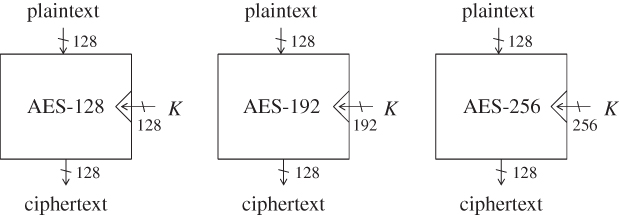
Figure 1.5 Three algorithms of AES
1.5.1 Specification of AES-128 Encryption
In high level, the 128-bit key K is expanded to eleven 128-bit subkeys ![]() according to the key schedule function, or KSF.
according to the key schedule function, or KSF.
- The 128-bit key K is set to the first 128-bit subkey
 .
. - The KSF is computed to update 128-bit subkey
 to another 128-bit subkey
  .
. - Similarly, the KSF is iterated nine times. In each time, 128-bit subkey
 is updated to another 128-bit subkey
  for
for  .
.
Then, a plaintext is encrypted to a ciphertext as follows:
- An XOR of the plaintext and the first subkey
 is computed, and this value is set to a 128-bit internal state value
  . This operation is often called whitening.
 - The 128-bit internal state value
 is updated to
  by computing a round function, which also takes as input subkey
  . This operation is called round 1 or the first round.
 - The round function is iterated nine times to update the internal state value
 to
to  . In round i, where
  , the round function takes as input
  and outputs
  . Note that the round function in the last round is slightly different from the other rounds. The last state that is
  is the ciphertext.
The computation structure of AES-128 in a function level is described in Figure 1.6.

Figure 1.6 High-level computation structure of the encryption of AES-128.  and
and  denote the round function and KSF, respectively.
  is the last round function, which is different from the other rounds
In practice, it is not necessary to compute all the 11 subkeys at the very beginning. For example, the last subkey will not be used until the very end of the encryption process. Thus, generating the last subkey and keeping it in a register is a waste of computation resource. In order to minimize the computation resource, the KSF and the round function updates are computed in parallel round by round. The AES-128 encryption algorithm in the function level can be described as Algorithm 1.1.
1.5.1.1 Preliminaries to Describe Computation Details
In AES, byte represents 8-bit values. AES is a byte-oriented cipher. All operations are defined at byte level. Let v be a byte value and ![]() be its bit-wise representation, of which the corresponding vector representation is
be its bit-wise representation, of which the corresponding vector representation is ![]() . In AES, each bit of a byte represents coefficients of polynomial of
. In AES, each bit of a byte represents coefficients of polynomial of ![]() :
:
A byte value can be represented in hexadecimal. For example, the byte ![]() represents the polynomial
represents the polynomial ![]() .
.
Addition
Addition of two bytes, ![]() and
and ![]() , returns
, returns
Multiplication
Multiplication in ![]() corresponds with multiplication of polynomials modulo, an irreducible binary polynomial of degree 8. The irreducible polynomial of AES is defined as
corresponds with multiplication of polynomials modulo, an irreducible binary polynomial of degree 8. The irreducible polynomial of AES is defined as
Because the multiplication by ![]() and
and ![]() is later introduced inside the round function, more details of the operation
is later introduced inside the round function, more details of the operation ![]() are explained here.
are explained here. ![]() is written as
is written as
When ![]() , the result is
, the result is ![]() according to the definition of byte. When
according to the definition of byte. When ![]() , the irreducible polynomial
, the irreducible polynomial ![]() is subtracted from the result. Subtraction is the inverseof the addition. Because the addition is the XOR, the subtraction is also a simple application of the XOR operations. Hence, the result is
is subtracted from the result. Subtraction is the inverseof the addition. Because the addition is the XOR, the subtraction is also a simple application of the XOR operations. Hence, the result is
According to the definition of byte, the result is ![]() .
.
1.5.1.2 S-box
AES uses a substitution-box (S-box) to mix the data. The S-box is used in both of the round function and the KSF, and thus is defined here. The S-box used in AES is a pre-determined bijective mapping from an 8-bit value to an 8-bit value. The definition of the AES S-box is shown in Table 1.6. Hereafter, the S-box transformation is described as ![]() . For example,
. For example, ![]() returns
returns 2f, and ![]() returns
returns 03.
Table 1.6 AES S-box
| Lower four digits | |||||||||||||||||
0 |
1 |
2 |
3 |
4 |
5 |
6 |
7 |
8 |
9 |
a |
b |
c |
d |
e |
f |
||
0 |
63 |
7c |
77 |
7b |
f2 |
6b |
6f |
c5 |
30 |
01 |
67 |
2b |
fe |
d7 |
ab |
76 |
|
1 |
ca |
82 |
c9 |
7d |
fa |
59 |
47 |
f0 |
ad |
d4 |
a2 |
af |
9c |
a4 |
72 |
c0 |
|
2 |
b7 |
fd |
93 |
26 |
36 |
3f |
f7 |
cc |
34 |
a5 |
e5 |
f1 |
71 |
d8 |
31 |
15 |
|
3 |
04 |
c7 |
23 |
c3 |
18 |
96 |
05 |
9a |
07 |
12 |
80 |
e2 |
eb |
27 |
b2 |
75 |
|
4 |
09 |
83 |
2c |
1a |
1b |
6e |
5a |
a0 |
52 |
3b |
d6 |
b3 |
29 |
e3 |
2f |
84 |
|
5 |
53 |
d1 |
00 |
ed |
20 |
fc |
b1 |
5b |
6a |
cb |
be |
39 |
4a |
4c |
58 |
cf |
|
6 |
d0 |
ef |
aa |
fb |
43 |
4d |
33 |
85 |
45 |
f9 |
02 |
7f |
50 |
3c |
9f |
a8 |
|
| Upper | 7 |
51 |
a3 |
40 |
8f |
92 |
9d |
38 |
f5 |
bc |
b6 |
da |
21 |
10 |
ff |
f3 |
d2 |
| four digits | 8 |
cd |
0c |
13 |
ec |
5f |
97 |
44 |
17 |
c4 |
a7 |
7e |
3d |
64 |
5d |
19 |
73 |
9 |
60 |
81 |
4f |
dc |
22 |
2a |
90 |
88 |
46 |
ee |
b8 |
14 |
de |
5e |
0b |
db |
|
a |
e0 |
32 |
3a |
0a |
49 |
06 |
24 |
5c |
c2 |
d3 |
ac |
62 |
91 |
95 |
e4 |
79 |
|
b |
e7 |
c8 |
37 |
6d |
8d |
d5 |
4e |
a9 |
6c |
56 |
f4 |
ea |
65 |
7a |
ae |
08 |
|
c |
ba |
78 |
25 |
2e |
1c |
a6 |
b4 |
c6 |
e8 |
dd |
74 |
1f |
4b |
bd |
8b |
8a |
|
d |
70 |
3e |
b5 |
66 |
48 |
03 |
f6 |
0e |
61 |
35 |
57 |
b9 |
86 |
c1 |
1d |
9e |
|
e |
e1 |
f8 |
98 |
11 |
69 |
d9 |
8e |
94 |
9b |
1e |
87 |
e9 |
ce |
55 |
28 |
df |
|
f |
8c |
a1 |
89 |
0d |
bf |
e6 |
42 |
68 |
41 |
99 |
2d |
0f |
b0 |
54 |
bb |
16 |
|
1 All the numbers in this table are in hexadecimal.
Note that the S-box and the inverse S-box transformations are not identical. As explained later, AES decryption algorithm requires the look-up table for the inverse of ![]() , that is
, that is ![]() .
.
1.5.1.3 State
The block size of AES is 128 bits. In AES, 128-bit data is called state. The 128-bit state consists of 16 bytes, and is represented as a ![]() two-dimensional array as depicted in Figure 1.7.
two-dimensional array as depicted in Figure 1.7.

Figure 1.7 AES state. Each cell denotes a byte
1.5.1.4 Key Schedule Function (KSF)
The 128-bit key K is loaded into a 128-bit subkey ![]() . Then,
. Then, ![]() is computed for
is computed for ![]() . The input
. The input ![]() is represented as a state. The state is further divided into four columns:
is represented as a state. The state is further divided into four columns: ![]() ,
, ![]() ,
, ![]() , and
, and ![]() . The output
. The output ![]() is computed column by column. At first, a temporary 4-byte value
is computed column by column. At first, a temporary 4-byte value tmp is generated by using the value of ![]() .
.
 .
.- Apply the S-box defined in Table 1.6 to each of the 4 bytes in
tmp. - Rotate
tmpby 1 byte. Precisely, let be the 4 bytes of
 tmp. Then,tmpis updated to .
. - XOR the pre-specified 1-byte constant
 to the first byte of
 tmp.
Then, by using the 4-byte value tmp, the next subkey ![]() is generated as follows.
is generated as follows.
 .
. .
. .
. .
.
The key schedule procedure for AES-128 is depicted in Figure 1.8.

Figure 1.8 Key schedule function of AES-128. The key schedule function is iterated for 
1.5.1.5 Round Function (RF)
The round function takes as input the previous 128-bit state ![]() and subkey
and subkey ![]() , and generates the next 128-bit state
, and generates the next 128-bit state ![]() . The round function consists of four transformations called SubBytes, ShiftRows, MixColumns, and AddRoundKey. It updates the state by following Algorithm 1.2.
. The round function consists of four transformations called SubBytes, ShiftRows, MixColumns, and AddRoundKey. It updates the state by following Algorithm 1.2.
SubBytes 
SubBytes is a byte-wise operation. It updates the state by applying the S-box defined in Table 1.6 to each of the 16 bytes of the state. It is worth noting that the ![]() operation is the only nonlinear one in the AES round function.
operation is the only nonlinear one in the AES round function.
ShiftRows 
ShiftRows is a row-wise byte positions swap. The state consists of four rows: row 0, row 1, row 2, and row 3. Each row of the state consists of 4 bytes. The ShiftRows operation applies a left cyclic shift by i bytes to the 4 bytes of row i. The ShiftRows operation is depicted in Figure 1.9.

Figure 1.9 ShiftRows operation
MixColumns 
MixColumns is a column-wise data mixing operation. It takes as input 4 bytes in a column and computes another 4-byte value. The same computation is applied to all of the four columns. Let ![]() and
and ![]() be the 4-byte input and 4-byte output, respectively. The
be the 4-byte input and 4-byte output, respectively. The ![]() is computed by the following matrix operation:
is computed by the following matrix operation:

Each element in the matrix is written in hexadecimal.
The ![]() operation was designed to satisfy the MDS property explained in Section 1.4.2.1. The impact of modifying 1 input byte always expands to all the 4 output bytes. More generally, the sum of the number of modified input bytes and the number of modified output bytes is always greater than or equal to 5.
operation was designed to satisfy the MDS property explained in Section 1.4.2.1. The impact of modifying 1 input byte always expands to all the 4 output bytes. More generally, the sum of the number of modified input bytes and the number of modified output bytes is always greater than or equal to 5.
AddRoundKey 
AddRoundKey updates the state by XORing the subkey ![]() to the state.
to the state.
Last Round Function 
In the last round (Round 10 for AES-128), the round function is different from the middle rounds. The ![]() operation is not computed that is, only the
operation is not computed that is, only the ![]() , and
, and ![]() operations are performed.
operations are performed.
1.5.2 AES-128 Decryption
To decrypt ciphertext C to P, the round function is applied in reverse order. The KSF is exactly the same. Eleven subkeys ![]() are generated from K. Different from the encryption algorithm,
are generated from K. Different from the encryption algorithm, ![]() is firstly used, and then the decryption is processed with
is firstly used, and then the decryption is processed with ![]() , and finally with
, and finally with ![]() .
.
Inside the round function, four operations are computed in reverse order. The inverse of the ![]() operation is exactly the same as the original
operation is exactly the same as the original ![]() operation because the XOR operation is involution.
operation because the XOR operation is involution.
For the inverse of the ![]() operation, the inversion matrix is required. Let
operation, the inversion matrix is required. Let ![]() and
and ![]() be the 4-byte input and 4-byte output to the inverse
be the 4-byte input and 4-byte output to the inverse ![]() operation, respectively. The
operation, respectively. The ![]() is computed by the following matrix operation:
is computed by the following matrix operation:

Each element in the matrix is again written in hexadecimal.
The inverse of the ![]() operation is relatively simple. It applies a right cyclic shift by i bytes to the 4 bytes of row i.
operation is relatively simple. It applies a right cyclic shift by i bytes to the 4 bytes of row i.
The inverse of the ![]() operation requires another table to substitute each byte value. The inverse S-box, denoted by
operation requires another table to substitute each byte value. The inverse S-box, denoted by ![]() , is defined in Table 1.7.
, is defined in Table 1.7.
Table 1.7 AES inverse S-box
| Lower four digits | |||||||||||||||||
0 |
1 |
2 |
3 |
4 |
5 |
6 |
7 |
8 |
9 |
a |
b |
c |
d |
e |
f |
||
0 |
52 |
09 |
6a |
d5 |
30 |
36 |
a5 |
38 |
bf |
40 |
a3 |
9e |
81 |
f3 |
d7 |
fb |
|
1 |
7c |
e3 |
39 |
82 |
9b |
2f |
ff |
87 |
34 |
8e |
43 |
44 |
c4 |
de |
e9 |
cb |
|
2 |
54 |
7b |
94 |
32 |
a6 |
c2 |
23 |
3d |
ee |
4c |
95 |
0b |
42 |
fa |
c3 |
4e |
|
3 |
08 |
2e |
a1 |
66 |
28 |
d9 |
24 |
b2 |
76 |
5b |
a2 |
49 |
6d |
8b |
d1 |
25 |
|
4 |
72 |
f8 |
f6 |
64 |
86 |
68 |
98 |
16 |
d4 |
a4 |
5c |
cc |
5d |
65 |
b6 |
92 |
|
5 |
6c |
70 |
48 |
50 |
fd |
ed |
b9 |
da |
5e |
15 |
46 |
57 |
a7 |
8d |
9d |
84 |
|
6 |
90 |
d8 |
ab |
00 |
8c |
bc |
d3 |
0a |
f7 |
e4 |
58 |
05 |
b8 |
b3 |
45 |
06 |
|
| Upper | 7 |
d0 |
2c |
1e |
8f |
ca |
3f |
0f |
02 |
c1 |
af |
bd |
03 |
01 |
13 |
8a |
6b |
| four digits | 8 |
3a |
91 |
11 |
41 |
4f |
67 |
dc |
ea |
97 |
f2 |
cf |
ce |
f0 |
b4 |
e6 |
73 |
9 |
96 |
ac |
74 |
22 |
e7 |
ad |
35 |
85 |
e2 |
f9 |
37 |
e8 |
1c |
75 |
df |
6e |
|
a |
47 |
f1 |
1a |
71 |
1d |
29 |
c5 |
89 |
6f |
b7 |
62 |
0e |
aa |
18 |
be |
1b |
|
b |
fc |
56 |
3e |
4b |
c6 |
d2 |
79 |
20 |
9a |
db |
c0 |
fe |
78 |
cd |
5a |
f4 |
|
c |
1f |
dd |
a8 |
33 |
88 |
07 |
c7 |
31 |
b1 |
12 |
10 |
59 |
27 |
80 |
ec |
5f |
|
d |
60 |
51 |
7f |
a9 |
19 |
b5 |
4a |
0d |
2d |
e5 |
7a |
9f |
93 |
c9 |
9c |
ef |
|
e |
a0 |
e0 |
3b |
4d |
ae |
2a |
f5 |
b0 |
c8 |
eb |
bb |
3c |
83 |
53 |
99 |
61 |
|
f |
17 |
2b |
04 |
7e |
ba |
77 |
d6 |
26 |
e1 |
69 |
14 |
63 |
55 |
21 |
0c |
7d |
|
All the numbers in this table are in hexadecimal.
1.5.3 Specification of AES-192 and AES-256
AES supports not only the 128-bit key but also the 192-bit and the 256-bit keys. For all the key sizes, round function is identical. The differences are the number of rounds computed and the KSF.
- AES-128 generates eleven 128-bit subkeys
 from 128-bit K, and the number of rounds is 10.
 - AES-192 generates thirteen 128-bit subkeys
 from 192-bit K, and the number of rounds is 12.
 - AES-256 generates fifteen 128-bit subkeys
 from 256-bit K, and the number of rounds is 14.
1.5.3.1 The Key Schedule Function for AES-192
The 192-bit key K is loaded into a ![]() array of bytes, which is denoted by
array of bytes, which is denoted by ![]() . Then,
. Then, ![]() is computed for
is computed for ![]() . The state is further divided into six columns:
. The state is further divided into six columns: ![]() ,
, ![]() ,
, ![]() ,
, ![]() ,
, ![]() , and
, and ![]() . The output
. The output ![]() is computed column by column. At first, a temporary 4-byte value
is computed column by column. At first, a temporary 4-byte value tmp is generated by using the value of ![]() .
.
 .
.- Apply the S-box defined in Table 1.6 to each of the 4 bytes in
tmp. - Rotate
tmpby 1 byte. Precisely, let be the 4 bytes of
 tmp. Then,tmpis updated to .
. - XOR the pre-specified 1-byte constant
 to the first byte of
 tmp.
Then, by using the 4-byte value tmp, the next subkey ![]() is generated as follows.
is generated as follows.
 .
. .
. .
. .
. .
. .
.
Among the 192-bit of the ![]() , the first four columns (128 bits) are set to
, the first four columns (128 bits) are set to ![]() , and the remaining two columns (64 bits) are set to the left half of
, and the remaining two columns (64 bits) are set to the left half of ![]() . Among the 192-bit of the
. Among the 192-bit of the ![]() , the first two columns (64 bits) are set to the right half of
, the first two columns (64 bits) are set to the right half of ![]() , and the remaining four columns (128 bits) are set to
, and the remaining four columns (128 bits) are set to ![]() . Similarly,
. Similarly, ![]() are obtained.
are obtained.
Note that ![]() is the last four columns of
is the last four columns of ![]() , and then
, and then ![]() is the first four columns of
is the first four columns of ![]() . The last two columns of
. The last two columns of ![]() are never used. Thus, in order to omit the redundant computations, the KSF should be processed up to the first four columns of
are never used. Thus, in order to omit the redundant computations, the KSF should be processed up to the first four columns of ![]() .
.
The key schedule procedure for AES-192 is depicted in Figure 1.10.

Figure 1.10 Key schedule function of AES-192. The key schedule function is iterated until 13 subkeys are generated
1.5.3.2 The Key Schedule Function for AES-256
The KSF for AES-256 can be similarly defined. The size of the key state is 256 bits consisting of ![]() -byte array. Each key state produces two subkeys, and 15 subkeys
-byte array. Each key state produces two subkeys, and 15 subkeys ![]() are generated.
are generated.
The update computation is very similar to the ones for AES-128 and AES-192. In order to mix the data quickly, another S-box layer is introduced between columns 3 and 4. The detailed procedure is omitted. The key schedule procedure for AES-256 is depicted in Figure 1.11.
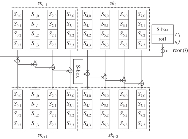
Figure 1.11 Key schedule function of AES-256. The key schedule function is iterated until 15 subkeys are generated
Note that ![]() is the first four columns of
is the first four columns of ![]() . The last four columns of
. The last four columns of ![]() are never used. Thus, in order to omit the redundant computations, the KSF should be processed up to the first four columns of
are never used. Thus, in order to omit the redundant computations, the KSF should be processed up to the first four columns of ![]() .
.

Figure 1.12 Notations for each state of AES-128
1.5.4 Notations to Describe AES-128
The computation of AES-128 with all the operations is described in Figure 1.12. The state after the first XOR of the plaintext and ![]() is denoted by
is denoted by ![]() . Similarly in round i, where
. Similarly in round i, where ![]() ,
,
- the state at the beginning of the round is denoted by
 ;
; - the state after the
 operation is denoted by
  ;
; - the state after the
 operation is denoted by
  ;
; - the state after the
 operation is denoted by
  ;
; - the state after the
 operation is denoted by
  , which is equivalent to
  .
.
As explained before, the state is represented by a ![]() -byte array. Using two subindices often causes misunderstanding, and thus each byte position is also denoted by a single sequence
-byte array. Using two subindices often causes misunderstanding, and thus each byte position is also denoted by a single sequence ![]() . For state S, the byte
. For state S, the byte ![]() , where
, where ![]() is converted to the byte
is converted to the byte ![]() . The byte positions in the single sequence are shown in Figure 1.13.
. The byte positions in the single sequence are shown in Figure 1.13.

Figure 1.13 Notations for inside AES state
Byte values of state S in several different byte positions ![]() are often denoted by
are often denoted by ![]() . For example, the 4-byte value in the column 0 of state S is denoted by
. For example, the 4-byte value in the column 0 of state S is denoted by ![]() .
.
- The first column, or column 0, of state S is denoted by
 , which is equivalent to
  .
. - The second column, or column 1, of state S is denoted by
 , which is equivalent to
  .
. - The third column, or column 2, of state S is denoted by
 , which is equivalent to
  .
. - The fourth column, or column 3, of state S is denoted by
 , which is equivalent to
  .
. - The first row, or row 0, of state S is denoted by
 , which is equivalent to
  .
. - The second row, or row 1, of state S is denoted by
 , which is equivalent to
  .
. - The third row, or row 2, of state S is denoted by
 , which is equivalent to
  .
. - The fourth row, or row 3, of state S is denoted by
 , which is equivalent to
  .
.
State ![]() becomes state
becomes state ![]() after the
after the ![]() operation. During this process, 4 bytes in
operation. During this process, 4 bytes in ![]() are moved to different byte positions in
are moved to different byte positions in ![]() . The moved positions are denoted by
. The moved positions are denoted by ![]() .
.
- For state S, 4 bytes of
 are equivalent to
  .
. - For state S, 4 bytes of
 are equivalent to
  .
. - For state S, 4 bytes of
 are equivalent to
  .
. - For state S, 4 bytes of
 are equivalent to
  .
.
Those 4-byte positions are called diagonal.
Similarly 4 bytes in ![]() are moved to different byte positions in
are moved to different byte positions in ![]() through the inverse of the
through the inverse of the ![]() operation. The moved positions are denoted by
operation. The moved positions are denoted by ![]() .
.
- For state S, 4 bytes of
 are equivalent to
  .
. - For state S, 4 bytes of
 are equivalent to
  .
. - For state S, 4 bytes of
 are equivalent to
  .
. - For state S, 4 bytes of
 are equivalent to
  .
.
Those 4-byte positions are called inverse diagonal.
Further Reading
- Daemen J and Rijmen V June 1998 AES submission document on Rijndael.
- Daemen J and Rijmen V 2002 The Design of Rijndeal: AES—The Advanced Encryption Standard (AES). Springer-Verlag.
- Deschamps JP 2009 Hardware Implementation of Finite-Field Arithmetic 1st edn. McGraw-Hill, Inc., New York, NY.
- Paar C and Pelzl J 2010 Understanding Cryptography: A Textbook for Students and Practitioners. Springer-Verlag, New York.