8
Summary and Future Developments
8.1 Introduction
The systems listed in Chapters 3, 4, and 5 have been described as individual or stand‐alone systems. This will be suitable for readers who have been given responsibility for a single system – for its design, its maintenance, or its procurement, for example. The systems diagrams will help to explain that there are almost inevitably interactions with other systems, and therefore, no system is truly ‘standalone’.
This situation leads to a number of aspects which must be considered in the design of an aircraft, quite apart from customer requirements, standards, and regulations. They make a significant contribution to the overall design and ultimately to fitness for purpose. Some of these aspects are discussed in this chapter and include the following:
- Systems of systems
- Integration
- Complexity
- Emergent properties
- Chaos
8.2 Systems of Systems
There are many circumstances in which one or more of these systems are combined to form a higher‐level system. This system will synergistically combine the various functions of the individual systems to form a function which is more comprehensive than the sum of its parts. Such a combination is often referred to as ‘a system of systems’. Example of such ‘systems of systems’ include the following:
- Propulsion (refer to Chapter 3)
- Navigation (refer to Chapter 4)
- Antennas (refer to Chapters 4 and 5)
- Weapon system (refer to Chapter 5)
- Military fast jet cockpit
- Flight deck of commercial airliner
8.2.1 Example of the Flight Deck as a System of Systems
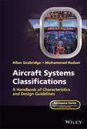
From the list of systems of systems above, the flight deck is presented as an example of the complexity of influences, and eventually in the complexity of the resulting design. The major influences are illustrated in Figure 8.1 and described in the following paragraphs.
These general influences can be considered in more detail and referred to the previous chapters as illustrated in Figure 8.2. Each of these influences will be briefly described, the descriptions are not intended to be complete but are to give an impression of the sort of analysis required that will result in a complete human machine interface – the interface between the crew, the systems, and the aircraft.
8.2.2 Customer Requirement
The customer may have specific preferences for the design of the flight deck, these may be ‘cosmetic’ and seen as deviations from a standard cockpit design or may indeed be revolutionary, based on their own preferences or to fit in with the design of one or more of the systems. An example of this is the preference by some aircraft designers for a side control stick rather than the centre control column.
8.2.3 Standards and Regulations
The design of the flight deck is governed by standards that may be national or international. There are some mandatory requirements and some are advisory, but all will provide a framework for health and safety, safety and comfort that provide aircrew with an environment that is fit for purpose.
8.2.4 Human Factors Aspects
- Comfort is essential for the well‐being of the crew who will have to remain in a constrained position for many hours with no opportunity for exercise. Comfort includes seating, temperature, humidity, and good quality air. Seating should minimise the risk of circulation issues such as deep vein thrombosis.
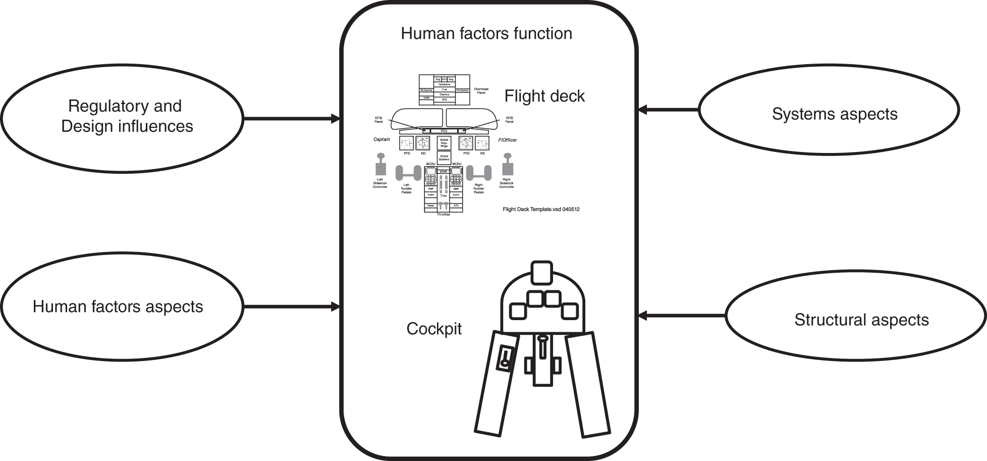
Figure 8.1 General influences on the design of the flight deck.
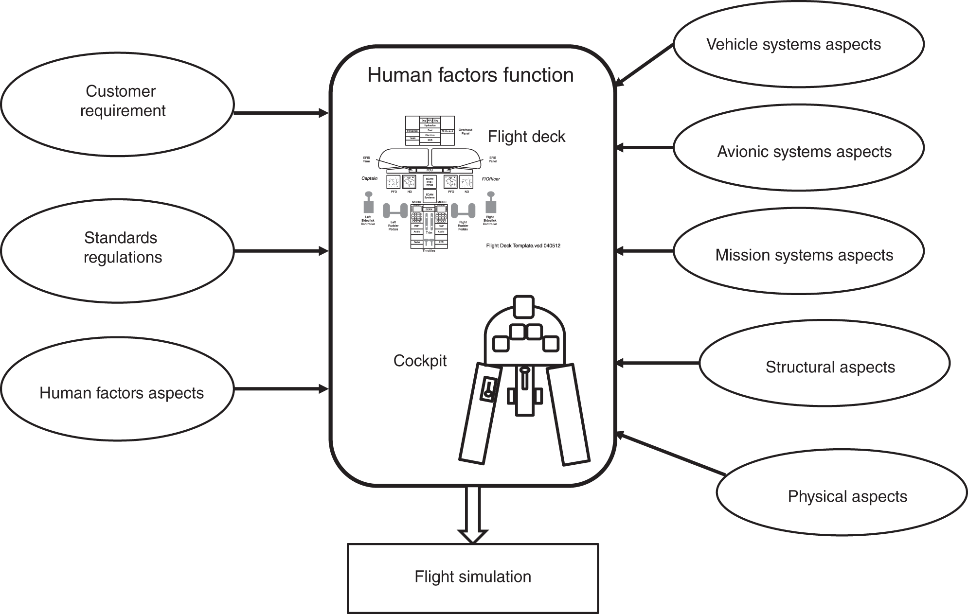
Figure 8.2 Detailed influences on the design of the flight deck.
- Viewing angles must be designed so that all displays and controls are visible by both pilots. In many cases, a pilot eye position is defined and viewing angles calculated with respect to that.
- External view is essential to allow the outside world to be viewed to the side and over the nose at all attitudes, during taxy, take‐off, and landing approach as well as for scrutiny of airspace to avoid other aircraft. Fast jet pilots requires all round viewing which may be supplemented by external cameras.
- Reach affects the controls on the side consoles which must be reachable by the appropriate pilot. Controls on the centre console, main panels, and overhead are generally to be reachable by both pilots within the percentile range agreed for the project.
- Lighting must be balanced throughout the flight deck and must allow for reading of documents and for viewing of all displays with no precedence given to any single display. The lighting must take into account day, night, and high‐altitude sunlight
- Consistent colour to be achieved throughout the furnishings to avoid distractions from the displays.
- Text and font size is to be to an agreed standard to ensure legibility without eyestrain. Critical parameters may be emphasised with colour or size of character or by flashing the message.
- Use of colour is selected to aid understanding and to provide emphasis and attention getting stimulus. The range of colours must be compatible with the lighting conditions and to obey standards and accepted preferences such as red, amber, green for warnings.
- Use of audio allows attention to be drawn to certain changes in conditions, especially when the crew may be engrossed in a particular task. The audio may take the form of one or more particular tones or the use of speech with clearly annunciated short phrases.
- Workload must be estimated by modelling the position of all items in the flight deck and all display and warning parameters and their implications on the ability of the pilot to perform the flying task. This estimate will be measured on flight deck rigs and on the final layout and confirmed in the flight simulator. Normal conditions and various failure modes must be modelled.
8.2.5 Vehicle Systems Aspects
Most of the vehicle systems will have an impact on the flight deck for display of status and for control actions. There are some controls that have traditionally occupied a prime position on the flight deck such as the throttles and control column and are almost fixed points around which the design is based. However, modern systems requirements and new technologies are challenging this supremacy. The following examples have a more profound on the design of the flight deck:
- Throttles (Section 3.1) are conventionally placed on the centre console of a commercial aircraft and on the left‐hand console of a fast jet. The throttles must be reachable throughout their range of movement and there must be no features that impede the movement. The throttle handles are a convenient place to install switches to complement the switches in the control column handle.
- Control column (Section 3.7) is the primary input to the flight control system. It is conventionally placed in front of each pilot on commercial aircraft, but modern designs have seen it move to the side console. In the fast jet, it is conventionally placed in front of the pilot, although some designs have adopted a side stick on the right‐hand console. The movement of the column has changed with time from a full fore and aft displacement to a limited displacement ‘force’ control. The control column handle is a convenient place to install switches to complement the switches in the throttle lever handle.
- Pressurisation (Section 3.5) demands that all opening windows and the canopy are sealed to prevent a loss of pressure. A slow loss of pressure leads to an insidious loss of capability to absorb oxygen and has led to loss of aircraft and life. Any items such as harnesses and ducts entering the flight deck or cockpit must therefore do so whilst respecting the pressure shell integrity.
- Pedals (Section 3.7) are used to control the attitude and trajectory of the aircraft through the flight control system and are also used to command the brakes and aerodynamic steering of the aircraft prior to the engagement of nose wheel steering on the ground.
- Equipment cooling (Section 3.12) is essential for some high dissipating equipment and ducts must be provided.
- Crew cooling (Section 3.12) is also essential and ducts and vents must be provided. The fast jet pilot must be provided with a high volume of cold air.
- Crew escape (Section 3.19) for fast jet pilots may require the installation of miniature detonating cord in the canopy material or devices to jettison the whole canopy. Notices must be displayed to warn ground crew of the hazardous nature of these devices.
- Ejection clearances (Section 3.19) must be observed with all fixed equipment mounted in the cockpit to ensure that the seat and the pilot can eject safely.
8.2.6 Avionic Systems Aspects
Most of the avionic systems will have an impact on the flight deck for display of status and for control actions:
- Displays and controls (Section 4.1) on legacy aircraft tend to be grouped or clustered, for example engine‐related displays will be grouped together, as will navigation, fuel, etc. On multifunction displays, the same grouping may occur but on separate pages of display and will not necessarily be presented at all times, usually on demand or following a failure. Visibility is important as is brightness, legibility, and clarity.
- Communication control panels (Section 4.2) must be accessible to all crew‐members.
- Navigation control panels (Section 4.3) will often be clustered on the centre console, close to the throttle levers.
- Electronic flight bag stowage and power connection (Section 4.16) is similar to carry on personal equipment. It must be stowed safely and may require a table or flat surface for a laptop device. A power supply cable must be provided but no other IT compatible cables to prevent connection to the aircraft systems.
- Lighting (Section 4.18) must be balanced to avoid any emphasis on particular areas of the flight deck, and it must be dimmable and must be compatible with night vision goggle requirements.
8.2.7 Mission Systems Aspects
The mission system of a military aircraft contains some elements of displayed parameters and control inputs. In many cases, these items need to be identified as belonging to the mission system and any control or switch input that could lead to weapon release must contain an interlock that makes inadvertent release extremely remote. This may take the form of covers or guards, or switches that require deliberate action to expose the switch.
- Head up display (HUD) (Section 5.4) is a key item of display in the cockpit and must be permanently situated to allow the pilot a direct view ahead with no reflections or obstructions. It may be necessary for the windscreen to be designed with a flat plane surface. On the commercial aircraft flight deck, the HUD can be sited on the front coaming or may be designed to fold down for landing.
- Weapon system (Section 5.14) demands that all controls and switches are clearly identified and may need an interlock such as a cover or wire locking. There will also be a requirement for wiring to be segregated from all other harnesses and additional shielding may be necessary.
8.2.8 General Aspects
There will inevitably be some items that do not fall easily into the discipline of the display system format for control and display demanded by multi‐function display units. These items include individual switches, lamps, and indicators that connect directly to the system for integrity reasons. Nevertheless, the location and appearance of these items must be subject to the human engineering design philosophy.
- Warnings may need to be provided independently of the multifunction displays, for example if they are needed in the event of total display failure. If this is so, then they must be visible and unambiguous and must meet the flight deck design philosophy.
- Switches and controls are not always integrated with a control panel or part of the multi‐function display. In such cases, a location must be found that is suitable for use and fits in with the flight deck design philosophy. Common locations are the overhead panel, the side consoles or the control column and throttle lever handles.
- Emergency oxygen cylinders and masks (Section 3.21) are provided for circumstances in which the pilots will need oxygen, for example after a loss of pressurisation, to recover the aircraft or effect a safe ejection. In both cases, pressurised oxygen cylinders are provided attached to the flight deck seats or to the ejection seat. Safety precautions must be taken to ensure that the cylinders are regularly checked for content and to reduce the risk of explosion.
- Emergency escape tools must be provided to assist in emergency evacuation of the aircraft and must be clearly labelled and stowed safely and easily accessible to flight crew and cabin crew.
- Personal items stowage must be provided to ensure safe stowage of carry‐on items on the flight deck. This included personal items, manuals, and laptops (now mostly superseded by the electronic flight bag). These items must not obstruct escape routes and must be stowed to withstand crash conditions.
8.2.9 Structural Aspects
The structure plays a large part in the installation of the systems, not least in the flight deck or cockpit. The cockpit in particular is contained within its own pressure shell and built into the structure. The equipment in the flight deck must be securely mounted on rails or in enclosures that are connected to the structure and in most cases, must withstand the crash case deceleration. Connections between the cockpit pressure shell and the airframe such as wiring harnesses, air ducts, hydraulic pipes, and control rods or cables must be installed so that they do not weaken the structure or compromise the pressure shell.
- Equipment mounting is provided with standard rails and fastenings to enable panels and equipment to be securely attached and rapidly removed and replaced. Security of attachment must meet the crash case conditions to ensure safety of the occupants.
- Cooling must be provided for some equipment and most certainly for the pilots. For commercial aircraft pilots, a comfortable shirt sleeve environment is preferred. Fast jet pilots will require cooling to provide comfort in high‐altitude solar radiation, wearing of flying suit, immersion suit, and g protection clothing. Much of the equipment mounted in the cockpit will dissipate heat and make a contribution to the heat load.
- Seat rails enable the seats to be adjusted independently to allow for different sizes and reach preferences for pilots.
- Sound insulation provides attenuation of external engine and aerodynamic noise to allow communications and systems status messages to be heard.
- Aerodynamics may be affected by the shape of the fuselage to accommodate the flight deck or cockpit – for example in fast jet trainers the fuselage shape around the cockpit may be longer or wider than a single‐crew version.
- Escape or evacuation facilities must be provided to allow the crew to depart the aircraft on the ground and in the case of fast jet military aircraft in flight at a wide range of speeds, height, and attitudes.
- Canopy installation for a fast jet aircraft must provide a means of ingress and egress under normal conditions, clear all round vision, and to allow the pilot to escape in emergency.
- Pressure seals are required to seal all opening windows and an opening canopy to maintain the integrity of the pressure vessel.
8.2.10 Physical Aspects
There are aspects of a general nature that need to require special attention because they cause incursions into the pressure cabin on a military fast jet aircraft and therefore need specialist connections to be formed.
- Power supplies routed to the flight deck or cockpit will enter via pressure bungs or connectors and may be separated from other wiring. Some items of equipment may require a circuit breaker panel to enable breakers to be reset.
- Cooling ducts must be provided through the partitions or floors with appropriate adjustable vents and fans. In the fast jet cockpit, the ducts will enter the pressure shell.
- Wiring harnesses through pressure structure in a fast jet must be provided by means of rubber bungs or suitable connectors.
- Security of access to protect against unauthorised access and forced entry is necessary as a result of the terrorist threat. This will take the form of a strengthened door and frame, an eye hole/lens, a key pad, and secure locks.
8.2.11 Flight Simulation
Flight simulation is included in this chapter because it is so intimately related to the design of the flight deck or cockpit. The flight simulator is no longer merely a training aid to allow pilots to convert to type and familiarise themselves with the flight deck. It is used during the development of a new aircraft as a means of confirming that its fidelity to the design is robust. It is used regularly to extend the pilot's expertise under normal and abnormal conditions of flight and in the military world, it is used to develop and perfect new operational techniques. The simulator is strongly influenced by the development of the human machine interface and this influence is two way – it is used to reflect and confirm any changes identified which are fed back into flight deck improvement.
8.3 Architectures
The systems architecture is a representation of the conceptual shape and form of a system which can be visualised quite independently of any physical implementation. It is an invaluable device for making a simple and easy to understand representation of a system using a block diagram format as a convenient shorthand notation. This simple visualisation allows a concept to be represented clearly and acts as a mechanism for promoting discussion between various engineering disciplines to reach agreement on interfaces, functional allocations, and standards. From such simple basic representations, it is possible to develop the architectures further without the need to move to excessive detail of wiring interconnections or detailed components. This is true for physical and functional representations in terms of software and hardware building blocks. It is especially useful for setting and agreeing boundaries and interfaces. Figure 8.3 shows a generic system architecture and the way in which it can be layered to illustrate top‐level architectures, major and sub‐system and even the architecture of individual items of equipment.
Apart from allowing design decisions to be made, systems architectures are an ideal tool to assist in identifying candidates for early trade‐offs and simple models using spreadsheets to perform cost, benefit, and performance comparisons between different architecture designs, see Chapter 7.
System architectures are discussed further in Chapter 5 of Seabridge and Moir. 2020.
Figure 8.3 Example generic system architecture.
8.4 Other Considerations
There are other considerations that are less easy to determine and model. Some of these appear as issues when systems are being tested or during flight test. In extreme cases, they appear when the aircraft is in service, when issues are costly to rectify. Some example considerations are discussed below, but the cautious system engineer will try to identify others.
8.4.1 Integration
Integration can be characterised by the performance of many functions by a small number of units. It is more commonly applied to avionics type systems, but is also found in major structural and mechanical systems such as aircraft powerplant and propulsion systems and even the airframe itself. In an integrated system, the individual systems interact with each other and display forms of ‘interconnectedness’ that makes the larger system more than the sum of its constituent sub‐systems. Interconnectedness of systems is achieved by
- Data communication networks conductive or optical.
- Direct physical interconnections by design, e.g. welded, fastened, or glued connections.
- Direct mechanical interconnections by drive shafts, air motors, or actuators.
- Indirect physical interconnections, e.g. thermal, vibration, and electrical conduction.
- Physical amalgamation at component level.
- Functional interconnection in processors by shared computer architectures, memory locations, or data use.
- Serendipity – emergent properties or unexpected behaviours in one system that affect one or more others.
There is little doubt that integration has brought advantages to the design of aircraft systems. There is better inter‐system communication and greatly improved functional performance. Integration has brought advantages to aircraft design, including the introduction of innovative technologies. Data is available on‐board in real time for use by crew, accident data recorder, maintenance management system, and flight test instrumentation. There has been a great improvement in the design of cockpits and flights decks with a consequently reduced crew workload.
System integration has been achieved by design and has been implemented by the application of readily available technologies by means of which functionality has been incorporated using a combination of
- Computing systems based on distributed computers
- High‐order languages
- High‐speed data buses
- Multi‐function displays and controls
- Touch, voice, and switch controls
All this has been enhanced over the years by the use of colour screens, high‐resolution images, easy access to on‐board databases for intelligence and maintenance data, access to ground‐based systems by data link and incorporation into the air transport management system. The cockpit or flight deck is now roomy, uncluttered, comfortable and a safe and clean place in which to work. The pilot is now integrated with the whole aircraft and its systems. This looks likely to continue with predicted technologies such as gesture control, synthetic vision and neural networks.
Some mechanical transfer functions such as those previously provided by mechanical devices such as cams and springs or hydro‐mechanical devices have been incorporated in software and electrical effectors, thereby blurring the distinction between mechanical and avionics functions. There are issues associated with each of these characteristics that need to be understood:
- Computing systems based on distributed computers: the functions in individual systems may be conducted in real time in a cluster of computers and are part of a complex network of more clustered computers. All of these will generally operate asynchronously.
- High‐order languages: the early choice of languages such as Pascal and Ada was based on their inherent rigid structure and the use of limited instruction sets to form a deterministic structure essential for the acceptance of safety critical software. As time progressed, this structure was seen as limiting in terms of speed, even cumbersome in its inherent inelegance of software design, and the computer games industry began to spawn languages more suited to graphics, visual effects, and high‐speed operations. The favoured language became C++ which is still prevalent today and has been adopted for aerospace applications, after early resistance. There are potential issues with its use (unless a limited instruction set is mandated) which can lead to non‐deterministic structures.
- High‐speed data buses: a similar sequence of events led from the initial choice of MIL‐STD‐1553B because of its simple and deterministic nature, towards the widespread use of high‐speed data bus structures which can also exhibit non‐determinism if not correctly designed.
- Multi‐function displays and controls have released panel space in cockpits and improved pilot awareness by the use of colour and easily understood formats for data and information. Much of this advance has come from the world of desktop computing and games. The perceived need to give aircrew information only when it is needed for a particular phase of flight means that data may only be accessed after several pages of information (screens) have been viewed.
- Touch, voice, and switch controls have increased the opportunity for overlaying visual screen information with other cues such as voice and aural tones to signify events. They have also increased the opportunity for instinctive reactions by the pilot in response to these cues. In a controlled environment, this is seen as an advantage, but in emergencies, it may result in an overload of information which is not permanently displayed – it needs to be remembered. Instinctive reaction may also lead to a response being less considered than a switch press action where the switch is on a panel and can be checked by a second pilot, rather than being a ‘twitch of the finger’.
The result of this is a perceived obscuration of the end‐to‐end behaviour of the system. This may be seen as an inability to be able to trace the route of an input signal to an output effector in a simple manner – once the way in which system behaviour was checked. There are severe implications to this obscuration:
- It is difficult to envisage the correct behaviour of any one individual system and the whole system for an observer and, more seriously, for a reviewer checking and signing‐off for correctness of operation.
- It is difficult to design a series of tests that go deeper than merely checking that an appropriate combination of inputs gives rise to an expected output and does not give rise to an unexpected output.
- It is almost impossible to verify the soundness and segregation of systems and to detect any unexpected interactions.
- It is difficult to determine the correct operation of the whole system – not simply the fact that functions have been performed correctly, but in understanding the mechanics of this.
- It is very possible that serious issues will remain dormant until a particular combination of events, demands, data structure, and software instructions leads to their initiation.
This all leads to uncertainty in the complete design unless something is done to improve the visualisation and understanding of the design, its implementation and the results of testing.
8.4.2 Complexity
It certainly appears that modern aircraft systems have become more complex, both as individual systems and as total systems. Some of the reasons for this include the following:
- Advances in technology have made it easier to implement more functions in software in a high‐speed processing architecture.
- The desire for engineering advancement: the simple need for engineers and designers to incorporate new functions and to apply new technology.
- The need for more automation in a bid to reduce crew workload.
- A desire for autonomous operations for unmanned vehicles and in the event of further reductions in flight deck crew complement.
- The desire to get more functional performance from fewer items of equipment.
As computing technology makes it easier to include new functions, so customer requirements are enhanced by the results of this and their needs become more complex. This may be spurred on by pilots flying new types and learning new techniques, thus making more demands based on their experience. Engineers are usually more than happy to entertain this scenario, as their natural inclination is to apply new technologies.
This desire is not solely restricted to the flying side of operations. Airline and military fleet maintenance and logistics support are also under pressure to improve turn‐around times. One method of doing this is to improve the accurate location of failures and to provide advance notification to the ideal repair and replacement bases. This has led to the introduction of more sophisticated algorithms to enable monitoring, on‐board analysis together with data link download of information. It has also led, incidentally, to scenarios in which faults can be ‘carried’ in redundant systems until the most cost‐effective repair base is reached.
This has the result of making the systems associated with control of the aircraft and mission to become closely connected to the maintenance function, further increasing complexity. Complexity is rarely a good thing in engineering. Despite the process of requirements capture, analysis, careful design, and robust reviews, many projects fail because of cost and time over‐runs. Much of this has to do with the impact of complexity. Complexity adds time to the design and test process as re‐work is required and because the task has been under‐estimated. It is important to try to assess or measure any trends towards increasing complexity and to focus attention on their solutions or to amend the estimate.
Complexity results in an increase in relationships between elements of the system. This is bad enough if the complexity is confined to a bounded system, but when the impact of integration blurs the boundaries of individual systems then the situation becomes difficult to control. Hence, the widening scope of integration to encompass external systems such as maintenance and air traffic management requires more diligence in design.
It is well then to make an assessment of a new system design to see if it has become more complex than its predecessors. This assessment can be used for a number of purposes:
- To determine what additional design and test work will be required.
- To determine what further investment will be needed in new design tools.
- To determine what new or additional skills will be required.
- To determine what training needs will be needed.
- To ensure that any work or cost estimates carried forward from a previous project are appropriately factored.
- As an aid to determining the feasibility of the project.
8.4.3 Chaos
The current situation of aircraft systems is that they have reached an advanced state of integration in which the ‘core’ or essential systems of the aircraft are themselves tightly integrated and are becoming an integral part of advances in navigation and air traffic management systems aimed at providing efficient navigation. In part, this is being driven by environmental issues aimed at reducing fuel burn and potential pollution of the atmosphere.
Figure 8.4 takes this further to illustrate how advances in external systems, many of them ground‐based and in continuous operation are also embracing the aircraft. In this way, the controlled operation of systems, with regular and relatively frequent power up and power down phases are now a part of a continuously operating system. Thus, there are fewer opportunities for system clocks to be reset and for memories to be refreshed.
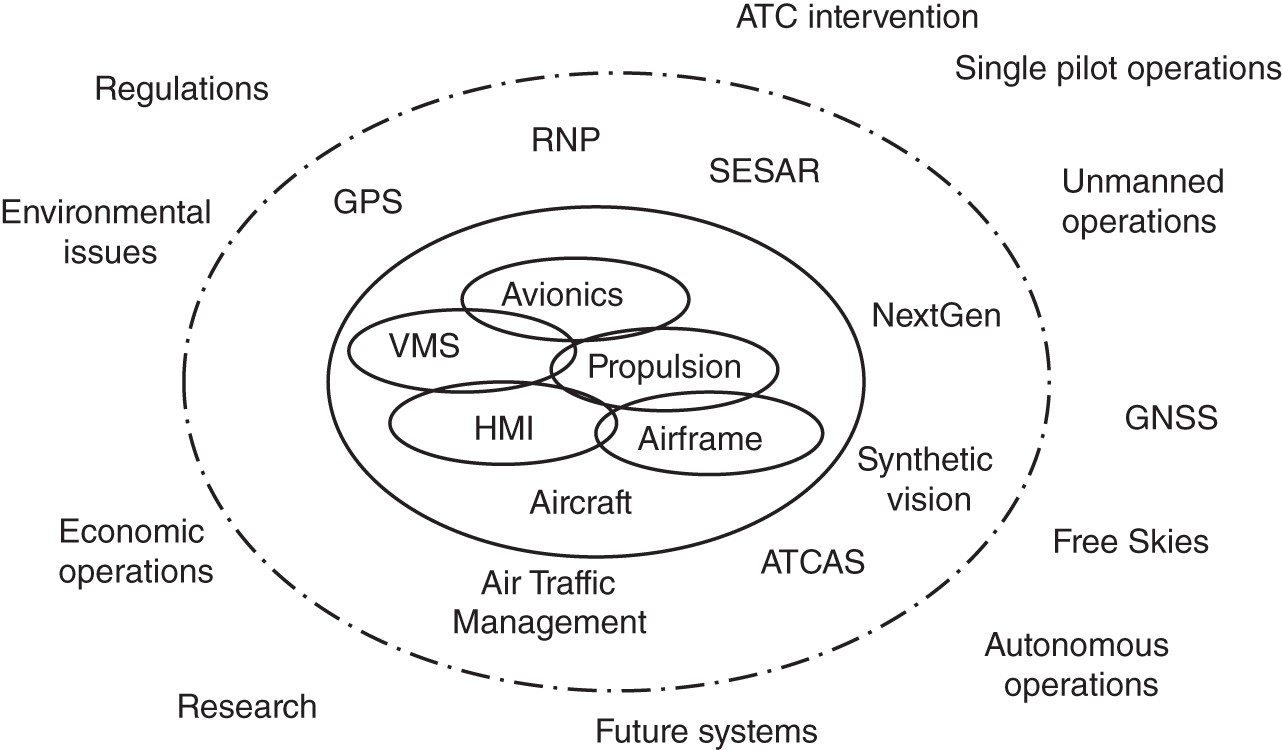
Figure 8.4 Increasing integration.
The ‘core’ systems can be represented by their own individual sub‐system architectures and can be visualised as a combined architecture. This illustration can be extended to encompass a complete aircraft architecture to give an example of the complexity of modern systems. This extension can be illustrated as a federated architecture or an integrated modular architecture. Each functional block in the extension should be considered as performing one or more functions which can be implemented in individual avionics boxes or integrated into some form of computing architecture with interconnecting data bus links. The functions are implemented in software and interconnected with some form of data bus. The message is the same no matter how it is implemented – it is complex. The system should be perceived as many functions performed in many computers, with instructions and data in software, and inter‐functional data embedded in data bus messages. There the systems will probably run asynchronously, and there will be many data items and many non‐linearities. It is likely that some processing structures and some data bus mechanisms will be non‐deterministic which may lead to variability in system timing. The system is also the recipient of random inputs from the human operators and maybe from external sources.
This situation leads one to pose a question about complex real‐time systems: ‘are there any conditions in which the system can become chaotic?’ Is there a risk that the whole system can enter a state of chaos?
At one time, the aircraft systems operated for short periods of time only in any one flight and were then powered down, and thus all conditions were re‐set. For fast jet military jets, the power up time might only be an hour or so, for long‐haul commercial airliners, maybe eight hours. Now with air‐to‐air re‐fuelling even fast jets are powered up for many hours, and airliners routinely remain powered up for days at a time. This situation arises on long‐haul flight of up to twenty hours where the systems are not shut down during the aircraft turn‐around interval. They are operating within an air transport management system that itself operates continuously.
As a result of some unexplained behaviours, it has been necessary to impose a mandatory re‐boot for the B787 and A350. This was reported in MRO‐Network.com under the header ‘EASA orders periodic reset of A350 internal clock’. The report described the issue of a European union Aviation Safety Agency (EASA) airworthiness directive AD 2017‐0129 mandating that operators power‐down the aircraft systems after a continuous period of operation of 149 hours. This was issued as a response to reports of loss of communications between avionic systems and networks. According to EASA ‘different consequences have been observed by operators from redundancy loss to a specific function hosted on the remote data concentrators and core processing I/O modules’. Shutting down and powering up (power re‐boot) has had some success in previous incidents. In 2015, a Federal Aviation Authority (FAA) directive directed a re‐boot of all B787s that had been powered up continuously for more than 248 days to prevent a computer internal counter overflow. A year later, software issues were reported to have re‐surfaced when flight control modules were found to reset automatically after 22 days of continuous power up.
There are a number of reasons that give rise to the question about chaos: aviation systems have moved from relatively short time scale durations to a situation in which some parts of the systems are in use continuously, and now airborne systems have moved to long duration power up. In this was they have closely approached the operating scenarios for ground‐based commercial systems – which have been known to produce unusual results.
The complexity of systems means that it is difficult to guarantee that some or all of the precursor conditions for chaos will not arise. In its ‘normal’ state, the total system operates with many transactions, iterations, rates, and asynchronous conditions. Inputs to the system will be provided by the operators on board such as first pilot, second pilot, cabin crew. There are situations in which some use of non‐deterministic software and data bus applications may arise. When installed in the aircraft there are many interactions in software and data bus, and many systems contain non‐linearities. These are all conditions in which chaos can arise.
- Is it possible for a transition to occur that will disturb the ‘normal’ state?
- Could this lead to unexpected system behaviour?
8.4.4 Emergent Properties
One issue associated with complexity and chaos is that of unexpected behaviours or emergent properties. This phenomenon has been seen in large ground‐based systems where a re‐boot, control/alt/delete or power down is feasible to reset the system.
There are many definitions of the term ‘emergent property’ to be found. Many of them include phrases similar to ‘behaviour exhibited by a collection of systems that is not exhibited by the constituent systems on their own’. This means that even if systems are individually tested rigorously, they may not behave as a collection of systems. It is to be expected then that a system of systems, integrated systems or even interconnected systems may produce unexpected behaviours. Some of these will be benign, but the risk is that some may lead to an accident.
Rigorous testing on the ground and in the air may reveal some of these behaviours. However, the test environment is carefully controlled and many of the tests are based on expected behaviours. Therefore, a system under test will not necessarily experience all the conditions that an in‐service system will.
It will be interesting to see if a model can be devised using artificial intelligence and synthetic reality to discover emergent properties. A major issue here is that a model, like the testing process, is a controlled environment.
8.4.5 Fitness For Purpose
The whole design and development process is intended to produce an aircraft that meets the customer's requirement throughout its life and in all defined environmental and performance conditions – in other words it is fit for purpose. The process of the development lifecycle, including testing, trials, and initial in‐service experience, is intended to demonstrate this fitness for purpose. However, if any unexpected behaviours or fitness shortfalls are found, they will often be discovered late in the lifecycle where their rectification is costly.
It is important to fully understand what fitness for purpose means for the whole aircraft, and what contribution each of the systems makes to this. This is where the issues of emergent properties, unexpected behaviours, and chaos can influence the demonstration of fitness for purpose. Some form of predictive model will be helpful in identifying any weaknesses in the design and development process that may indicate a deviation from the path to demonstration of fitness for purpose.
8.5 Conclusion
This book has provided an illustration of aircraft systems as recognised in many types of aircraft in the aerospace industry. The industry is currently dominated by the need to deliver hard products, many of them complex interactions of airframe, components, human operators, and systems – both hardware and software. These products are provided to customers as a part of their armed forces or airline infrastructure, which in turn may be part of a wider national or international entity. This increasingly complex nature of products has led to an approach to dealing with them as complex systems.
An understanding of what constitutes a system is important. There is an increasing tendency for domain‐specific engineers to take a broader view of their system, a state of mind that is stimulated by the increasing integration of systems in the modern aircraft. Thus, individual systems are perceived as being sub‐systems of larger integrated systems existing in complex environments.
Chapters 3, 4, and 5 introduced the systems of an aircraft individually classified as vehicle, avionics, and weapon systems respectively. In the system diagrams used to describe individual systems, some aspects of interactions with other systems are shown. This must not be taken as definitive – specific solutions will contain different interactions. Chapter 6 briefly introduced some external systems to which aircraft are routinely connected. Systems architectures are a convenient method of visualising emerging concepts in both functional and physical form. The block diagram is a convenient notation for identifying the form of systems and is used as a medium for brainstorming, debate, and discussion. Chapter 7 briefly introduced this topic and presented and a method of modelling architectures to aid selection of the most appropriate solution.
8.6 What's Next?
The aerospace industry has a long history of innovation and new opportunities will arise from new scientific discoveries. These will be turned into new technologies by an industry that has great enthusiasm for new technology. Technology advance will continue to provide a focus for implementations to gradually improve the performance of aircraft or to provide solutions for specific problems. A brief scan through current literature reveals the following topics that will be developed over the next decade:
The flight deck or cockpit will undoubtedly transform from a physical entity into a virtual environment. This can be accomplished in the fast jet cockpit using sensors and display in the helmet, whereas the flight deck can be realised with goggles, now familiar in a number of training aids to provide a virtual environment. An example of this is shown in Figure 8.5.
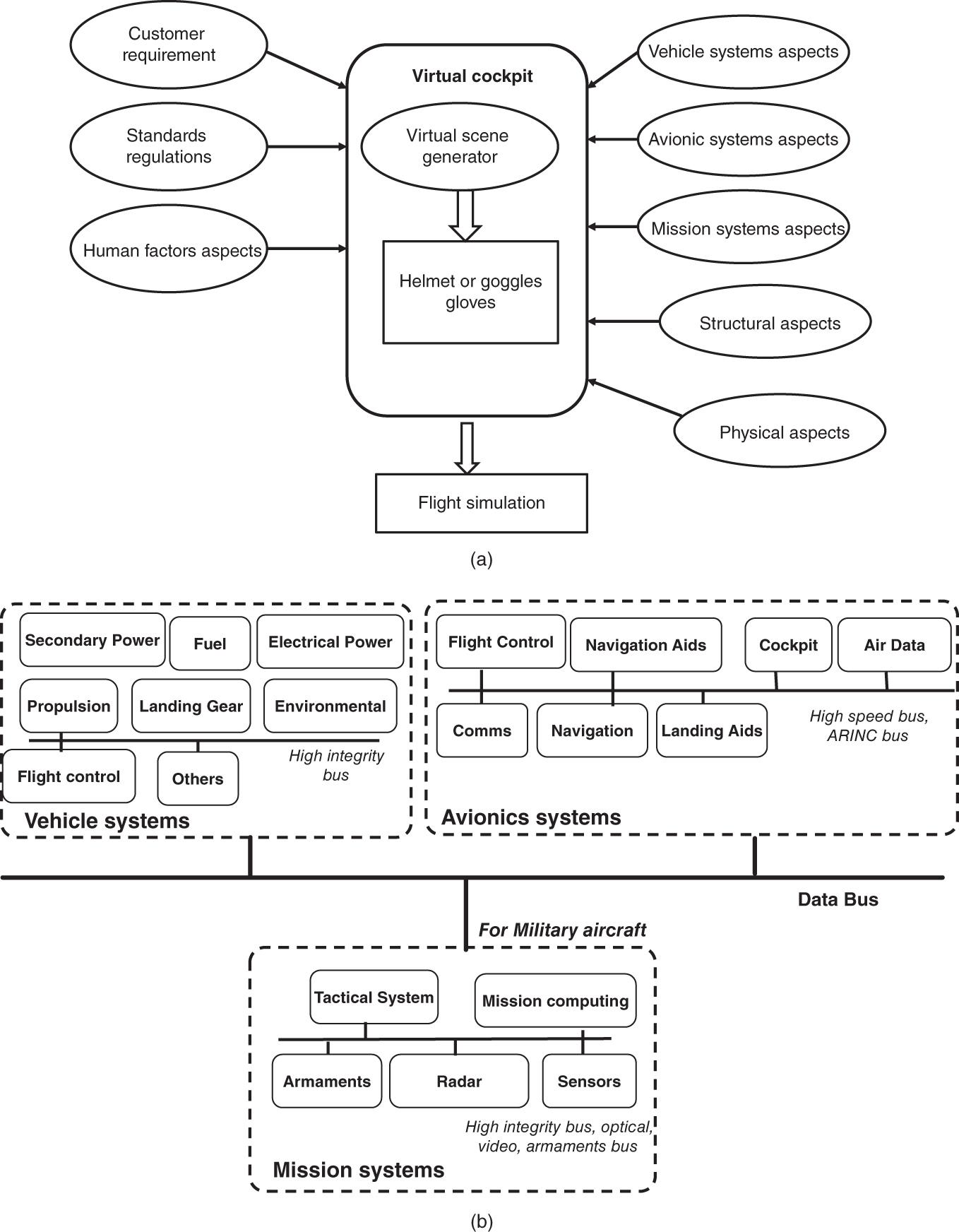
Figure 8.5 The virtual flight deck or cockpit.
There are safety issues with this approach which must to be considered in the design. The most obvious example is the redundancy offered by multiple physical display surfaces. This allows the continuation of the flight with the loss of one display surface, and allows cross‐checking by pilots of each other's displays.
There will be more changes as systems become more integrated with the development of extended reality, virtual controls, and displays and the increase in AI driving more automation and autonomy.
Computing has been at the heart of most advances in aircraft systems since the emergence of microprocessors suitable for use in aircraft applications in the 1970s. Changes in technology have resulted in faster computers and denser memories, and the application of these technologies in the commercial field of home computing, games, and Internet applications have been put to good use in aircraft systems. Artificial intelligence algorithms in design and in real time on‐board applications will benefit from neuromorphic computing for fast and energy‐efficient processing. This will have an impact on real‐time pattern recognition, speech processing, and image classification. This will affect the design of intelligence gathering, sensor processing, human factors design and navigation systems in future aircraft and may pave the way towards unmanned passenger aircraft with real autonomy. The main benefit of neuromorphic devices is their lower‐energy demand and the potential to incorporate more processing power into smaller volumes. This is predicted to improve over the next three decades, exceeding the predictions of Moore's law.
One use of this advance in computing will be the ability to move towards synthetic vision in cockpits and flight decks. To some extent, this has been applied in head‐up displays and in cameras mounted to provide all round vision from within the aircraft – a perceived spherical view by the pilot. Artificial intelligence (AI) and learning software techniques will lead to the provision of such facilities as object recognition and avoidance, techniques being developed for autonomous road vehicles. There is a danger that this can lead to an overload of information in the cockpit unless robust human factors approaches are applied. Techniques such as only displaying the required contextual information to an operator at a point in time and managing certain tasks on the operator's behalf will be applied to control the workload. Emerging analysis models such as trusted reasoning and trusted AI will be used to increase the certainty in which systems can be understood and tested.
There will always be a need for high‐energy systems to control the attitude of air vehicles, and there will continue to be a move towards electrical rather than hydraulic or pneumatic effectors. This will stimulate a demand for electrical actuation and electro‐hydrostatic systems with a need for electric motors with materials capable of operating at higher temperatures, higher magnetic field strengths, and rotational speeds using in‐built failure prediction software which will greatly improve flight and engine control systems. This is expected to improve power and rate performance of control surfaces at reduced mass.
It has been shown that power demand on successive generations of aircraft is growing. Despite the promises of lower power requirements of succeeding generations of semi‐conductors, this always off‐set by an increasing demand for more processing power. To reduce generated power and large heavy generators connected to the main engines, it is expected that next generation thermo‐electric generators will be used to scavenge waste and rejected heat sources to convert thermal energy directly into electrical energy. This can be used to capitalise on waste engine heat from engines, auxiliary power units, brakes, and avionics sources. There have been studies on how to use heat generated by the brakes to contribute to the energy needed to taxy an aircraft. A slight dilemma arises here, in that one of the major heat generating systems on an aircraft is the hydraulic system, and of course, its replacement by electrical systems is already being predicted.
On the subject of electrical power, it is expected that electrical generation components are likely to be embedded in the shafts of future engines. Engine manufacturers have been pursuing this for some time, and it is now very likely to happen.
Composite materials have been changing the approach to design and manufacturing over the past 30 years to great advantage in commercial and military aircraft types. New materials such as graphene will pave the way for novel approaches to structure design and for the design of electronic equipment housings which may require alternative approaches to screening and bonding.
A serious interest in environmental issues is at last moving away from simply banning the use of materials and substances and towards a creative use of technology and techniques to reduce carbon emissions. This has resulted in studies for different ways of operating aircraft and for different shapes and propulsions solutions. This, in turn, has led to consideration of novel sources of fuel being sought for cleaner combusting engines.
In the avionic systems of the aircraft the electrical wiring, generally copper with shielding and insulation is a contributor to weight, and it needs a large volume of the fuselage interior for harnesses or bundles of wire (many 10s of kilometres), connectors are always a contributor to faults and the whole assembly is costly. Testing and repair are further costs. Despite the widespread use of data buses including some fibre‐optics, there is still a lot of wiring in an aircraft. In the military data‐centric world, the introduction of new mission computers, real‐time video capture, high definition cockpit displays, and advanced electronic warfare systems means extensive re‐wiring for updates. Future systems will need to make greater emphasis on optical networks and signal multiplexing, novel mechanisms for incorporating wiring or optical fibres into the airframe structure and using transceivers. The commercial aircraft industry is leading the way with fibre optical backbones in the A380 and B787.
The scope of unmanned aircraft has expanded since their inception. Full‐size military vehicles are common with remote piloting and now the concept of a single aircraft accompanied by a swarm of ‘colleagues’. The role of vehicles has also expanded from military applications to commercial and civilian uses for peace‐keeping, policing, and purely civil uses. As yet, the carriage of passengers in unmanned vehicles has not happened, but with autonomous road vehicles and trains, it can't be far away. This will have an impact of the design of the vehicle. Without the mass of a pilot and the volume required, the ‘flight deck’ or ‘cockpit’ functions will remain on the ground.
There will be many changes and the world of ‘systems’ will develop to provide the functions of vehicle systems and avionic systems in a completely different way.
Exercise
- 8.1 What sort of properties will be required of a system model to enable it to predict emergent properties?