
Chapter 16
Overcoming Complexity: Formal Modeling Techniques at the Rescue
16.1 Introduction
As we have seen in Chapter 6 the Availability Management Framework (AMF) [48] performs its task based on an information model, and in particular the configuration information contained in this model. This model defines the scope within which AMF manages the availability of the services. That is the guarantees AMF can provide with respect to service availability (SA) is built into the model.
The model describes each entity AMF should manage as objects of the classes we touched upon in Chapter 6. Among them the configuration object class describing an AMF component defines over 20 configuration attributes all of which need to be considered when constructing the configuration for AMF. It is easy to see how the task of designing a configuration, which is not only syntactically and semantically correct – that is compliant to AMF's expectations – but that also guarantees the availability and maybe other characteristics of the system becomes a designer's nightmare if it needs to be done manually.
The Platform Management service (PLM) [36] presented in Chapter 5 requires a similar model, but it poses somewhat different challenges. Here the main issue is to make sure that when PLM collects the platform information from the Hardware Platform Interface (HPI), it needs to be able to map the detected configuration into the provided configuration model in a deterministic way. For example, one may have two similar hardware elements that are expected to run different execution environments. If the execution environment software is installed in such a way that it can boot only on one particular hardware element then the configuration needs to contain enough information for PLM that it can distinguish the hardware elements and does not try to force the wrong one to boot the execution environment.
As for the Software Management Framework (SMF) [49] discussed in Chapter 9 it needs to manipulate the entire information model to express the configuration changes for all the effected services. That is the combination of the above models and it expects this information as an input in the form of the upgrade campaign. Just like AMF, SMF also provides guarantees only within the scope of the upgrade campaign and the actual configuration it manipulates.
With all that we wanted to illustrate that designing a correct configuration for AMF or PLM and maintaining the system through upgrade campaigns is a challenge and requires significant brain power.
We can describe the problem in a different way: Building and maintaining a system that can provide highly available services on a continuous basis requires some efforts from the system and application designers and developers as well as from the system maintainers, the system administration. We can look at the SA Forum services – primarily the two frameworks AMF and SMF – as ways to shift the complexity of the task from the system maintainers and administration side toward the designers and developers because the design and development can be performed offline while maintenance and administration in high availability systems always mean online manipulation that may jeopardize the system. Simplifying these tasks in an inherently complex system is essential. However with shifting the problem from one desk to another we did not solve it. We still need a solution but because we want to solve it offline we can deploy tools of a wider range. We can use formal modeling techniques typically not considered – at least for the time being – for live systems.
We also look at them in a somewhat different context. Traditionally these techniques were designed and developed to support the software development process, that is, to ensure fault free software that satisfies the requirements. Accordingly the design process started with the requirements specification, followed by the design of the models, which could be validated and refined until they were ready for deriving the software of higher quality.
We believe that such methods and techniques are relevant to software management at configuration design time as well as at the design of upgrade campaigns, which deploy new configurations.
In this chapter we first present a high level overview of the relevant formal modeling techniques and the prerequisites the SA Forum specifications offer to enable their application. Subsequently we discuss in more details the approaches one may want to take to resolve the issues at hand. Throughout the chapter we reference work that has been done in the MAGIC1 (Modeling and Automatic Generation of Information for Configuration and upgrade campaigns for SA) project that we invite the reader to study if interested in further details.
16.2 Background
16.2.1 The Model-Based Approach
The Unified Modeling Language (UML) [59] – as it name indicates – is a modeling language standardized by the Object Management Group (OMG). It is widely accepted by the academia as well as by the industry. It defines a set of notations including class diagrams, sequence diagrams, state charts, and so on, to describe different aspects of systems such as its structure and behavior. It uses primarily graphical elements to facilitate intuitive understanding and it does not impose strict formalism.
To achieve well-formedness, and improve the formalism, UML is complemented with a textual formal language, the Object Constraints Language (OCL) [111] to express constraints on elements of a UML model and which can also be used as a query language to extract elements from a model. OCL is based on first order logic.
OCL is also used together with the Meta Object Facility (MOF) [112], OMG's standard for defining meta-models such as the meta-model of UML itself.
OMG has defined also different extension (or specialization) mechanisms for UML to tailor it for a particular domain and define what is called a UML profile. Through the specialization, UML profiles become more concise and formal than UML itself.
Model Driven Engineering (MDE) [113] reduces complexity by raising the level of abstraction. The idea is to start out with a high level overall picture of the target system and refine it with more and more details step-wise until a low level description is obtained that then can be transformed even automatically into the target code. Throughout the cycles of refinement validation and verification techniques can be used to guarantee that the refined model still satisfies the requirements set out at the beginning as well as the overall description is consistent and obeys the rules of the particular domain.
UML has been designed to support MDE and accordingly OMG defined its own approach referred as Model Driven Architecture™ (MDA™) [114, 115]. Its primary goals are portability, interoperability, and reusability through architectural separation.
UML is not well-suited for all the areas where formal methods and techniques have been used. For example, there exist notations and techniques better suited for the analysis of nonfunctional characteristics such as performance or our main concern availability. Techniques based on Petri-nets or Markov chains have been in use for decades [116] to determine these system characteristics. To apply them to a system described in UML, the model needs to be transformed into these formalisms.
16.2.2 Starting Points in the Specifications
MDE and MDA have been deployed mostly for code generation to raise the level of abstraction and improve quality of (prevent faults in) software. This is a valid goal in case of applications developed for SA Forum clusters and they need to follow the MDE/MDA concepts. In this chapter however we want to explore whether the same paradigm can be applied to other artifacts the SA Forum cluster needs.
AMF and some other services perform their task based on a configuration that describes the different entities they need to manage. The problem with such configuration information is that it is a significant amount of interconnected data. Any piece of it has dependencies and relations to other pieces and they should change in a consistent manner. It is like a spider net when it is touched at one point, the whole web reacts.
As we pointed out in Chapter 4 this configuration information is part of the SA Forum information model managed by the Information Model Management service [38] discussed in Chapter 8. It is described in UML, which is used in a somewhat specific way as described in Chapter 4. But the actual semantics, the behavior that defines the interdependencies between the different model elements are described in the text of the relevant service specifications. That is, they are not formalized.
Nevertheless the UML model itself is a good starting point for the formalization. As we mentioned OCL can be used to add the constraints to the UML model elements to formalize the textual descriptions of the specification.
A formalized configuration model describes the target for a site designer who needs to develop the site configuration. To create a configuration the designer has some requirements:
- the target system needs to provide some services, which may be characterized by functional and also nonfunctional requirements;
- there is a set of software that may be used to provide these services; and
- there is a cluster, a set of nodes to run that selected software.
We have presented one piece of this puzzle in the SMF in Chapter 9 at the discussion of the information flow envisioned by SMF.
The SMF specification includes the definition of the entity types file (ETF) XML (eXtensible Markup Language) schema [90], which is the means intended for software vendors to describe in a formalized way their software with respect to the SA Forum information model and in particular with respect to the different service entities. At the time of writing these are the AMF entities.
The SA Forum specifications describe the service configuration and the related semantics and the idea behind ETF is to describe the software intended for these services in similar terms. This description implies a range of deployment options so that different configurations could be derived to satisfy different systems and user requirements. That is, the ETF describes the prototypes for the entity types that can be deployed in particular systems.
From the perspective of formalization we again have a semi-formal description in the form of the XML schema the semantics for which is given in the text of the relevant specifications or even worse, implied through the entity types to be derived.
The ETF contents is the starting points for the configuration development therefore its model is an input for an automatic configuration generation process.
Unfortunately generating configurations does not solve all our headaches with the maintenance of a system designed for SA. Such a system has a long life-cycle during which it goes through numerous upgrades and reconfigurations.
The SA Forum specification dealing with these system aspects is again the SMF. As presented in Chapter 9, besides the ETF XML schema it also defines an XML schema to describe upgrade campaigns [90].
An upgrade campaign specifies the process, which migrates a system from one deployment configuration to a new desired one. One may consider this upgrade campaign specification similar to some interpreted code which guides the SMF implementation: SMF applies the upgrade campaign to the current system configuration and executes the resulting interpretation.
If we have a running system deploying a configuration to provide some given services and we have also generated a new configuration for the new (modified) requirements, the comparison of the two would identify what we need to change in the deployed configuration, that is, the target for the upgrade campaign we need to run.
If the new configuration is generated then the naming of the entities in the running system may not be consistent with the naming in the new one. We cannot use the entity features either for the mapping, since the whole purpose of the upgrade is to change features of the software entities. Therefore the mapping of the current and the desired configuration becomes a challenge.
Of course once we have identified the differences we still need to figure out the proper grouping and ordering of the upgrade procedures to be able to specify the upgrade campaign that SMF can apply to take the running system to the new desired configuration. As long as the comparison shows that only the software version changes, but not the arrangement of the software entities the upgrade campaign is relatively straightforward. However to truly take advantage of the new features of the software the arrangement of the entities such as the service group redundancy model may need to be changed as well. There might be none or more than one possible upgrade processes that maintains SA and we may need to evaluate which one suits best the constraints of the system. Besides avoiding potential service outages we need to consider dependencies and compatibility issues that do not occur in a stable running system, but characteristics of such transitioning periods.
We have to say up front that we cannot answer all these questions and it is not our goal to do so in this chapter. Nevertheless we would like to offer some ideas and discuss the experience learnt in the course of the MAGIC project mentioned in the introduction. The results of this project have been published in numerous papers that we are going to reference so that interested readers can investigate the subject beyond our high level overview.
16.3 Model-Based Software Management
16.3.1 Configuration Model
To apply any type of formal method we need to have a formal description of our problem domain, that is, a description free of any ambiguity. We need a model that we can manipulate according to some logic that finds a solution to our problem or determines that there is no solution.
The SA Forum information model is described in UML, but as we pointed out in Chapter 4 the primary goal of this model is to reflect the system status for the system administration and also to support the SA Forum services in performing their task. This is not that same task as reasoning about the correctness or constructing a valid configuration, which requires more information – information which is provided only informally in the specification text.
For reasoning about the correctness of the configuration we need to extend the UML model defined by the specifications with the constraints that describe the interrelations between the different model elements and their attributes. Most of these are currently hidden in the text of the relevant specification.
We use the word hidden on purpose because the specifications define the system runtime behavior. For example, in the AMF specification one of the main emphases is on the (component) service instance (SI) assignment distribution among the service units (SUs) and their components. This is only performed at runtime and it is not part of the configuration information. At the same time it has certain implications that need to be satisfied at configuration time so that the specified behavior can be performed at runtime. For example, if the redundancy model indicates that five assignments need to be given out for a SI then at least five SUs need to be in the protecting service groups.
The extent to which one is able to identify these rules in the specification determines the powerfulness of the model. Since the information model is described in UML, OCL could be a suitable language to describe the related constraints.
When trying to formalize these constraints one realizes quickly that, for example, the AMF information model is defined in such a way that it emphasizes similarity to suit the management needs and accordingly few classes are defined with mostly optional attributes. The mandatory attributes define the conditions when the optional attributes are used, which in turn have some relation with other attributes.
This conditional nature of attributes complicates the constraints definition of this already complex domain. A way to deal with complexity is to refine the standard model following the classification presented in the standard and define a class hierarchy where each class contains only the attributes appropriate for the subclass, following the basic object oriented principles.
Another nuance that one has to pay attention is that the standard information model defines the multiplicities in such a way that the Information Model Management service managing the model can accept incomplete configurations so that the model can be changed at runtime, for example, during a system upgrade. But when we want to determine whether a configuration is correct or not from the perspective of stable operation, it needs to be complete.
This shows that one may have different versions of the completed model depending on the system's mode of operation. For example, the verification that the system will transition through valid configurations during an upgrade implies a different notion of validity than when it is checked for normal operation mode.
Within the MAGIC project the work has been completed for the AMF information model and the results reported in [117, 118]. It encompasses an AMF domain model and a UML profile for AMF that can be plugged into an appropriate UML CASE (Computer-Aided Software Engineering) tool to create and validate AMF configurations.
It turns out that the general question whether a service group can protect all the SIs assigned to it is an nondeterministic polynomial-time hard (NP-hard) problem for most of the redundancy models as shown in [119] and therefore we cannot guarantee the answer in all cases within a polynomial time even using these techniques. However for SA this is a very important question (an important property of the configuration) and because of its NP-hardness we resort to heuristics to resolve it as proposed in [120].
The work referenced so far used as its starting point the UML model defined in the AMF specification and defined a new UML profile for AMF.
However others may approach the problem differently and base their work on results of the work done in the field of real-time embedded systems. Several UML profiles have been defined and among them Modeling and Analysis of Real-Time Embedded systems (MARTE) [121] for real-time embedded systems, which is the basis of the Dependability Analysis Modeling (DAM) [122] profile – an extension to cover dependability analysis. Depending of the ultimate goal of the model these can serve as starting points as well.
16.3.2 Configuration Generation
After we formalized our target – the system configuration, we are able to reason and construct valid configurations. UML CASE tools, for example, can take a UML profile and guide the user in crafting a syntactically valid configuration. This is however still a manual process and may involve a lot of guessing work on the site designer's side until he or she gets it right so that the tool throws no more errors. Meanwhile his or her focus is divided between the errors and the requirements the configuration would need to satisfy.
Knowing the dependencies built into the profile one can come up also with a systematic approach to construct valid configurations, which then can be turned into a deployable implementation.
16.3.2.1 Inputs for the Configuration Generation
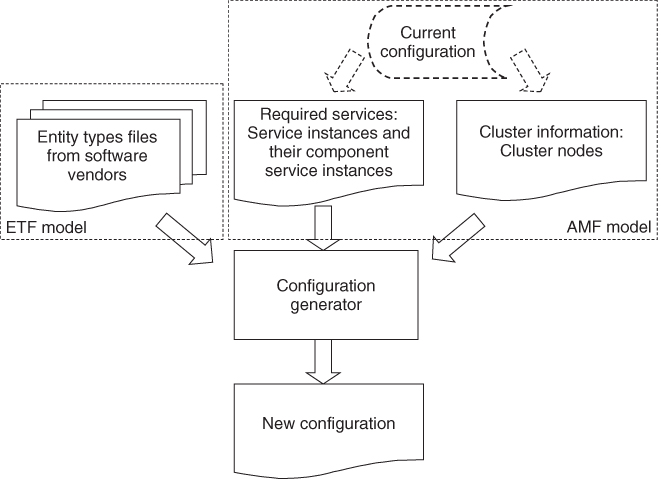
As we mentioned in Section 16.2.2 to design a configuration one needs to start with the services the system needs to provide, the description of the software that can be used to provide these services, and the cluster on which the software will be deployed to provide these services.
Within the SA Forum information model the application services are reflected only in the AMF information model. They are the SIs provided and protected by service groups. The actual assignments are performed at the component service instance (CSI) level as AMF selects the components most appropriate for the job.
Since only the site designer knows the services that the target system needs to provide, he or she needs to define the SIs and their CSIs. If the target site exists, that is, its reconfiguration or upgrade is the goal then the information can be collected from its current configuration together with the cluster information.
This also means that the AMF model itself can be used to represent these inputs.
With that we can slightly reformulate our goal: We want to generate the configuration of service provider entities – components, SUs, service groups – that are capable of providing and protecting the SIs and their CSIs the system needs to provide and distribute them on the cluster nodes; all in a way that satisfies the constraints imposed by AMF.
A software component is the execution of some software, which is installed in the system. This software typically is developed by a software vendor who describes its product in terms prototypes in an ETF. The ETF needs to include at least the prototypes for the components that can be instantiated from the software and the CSIs these components can provide. Other prototypes need to be present only if there are limitations on how these basic prototypes can be combined.
Here we need to take a short detour as the format of the ETFs is defined by an XML schema and the semantics is described in text. So the situation is similar to the AMF configuration except that it is not provided initially in UML. The reason for that is that ETF is expected to be packaged and delivered together with the software for which XML is much more suitable.
Looking at the actual contents of the schema it is easy to see that it maps well into a UML model therefore the formalization process we described in Section 16.3.1 applies easily to ETF as well and we can create an ETF domain model and profile.
Figure 16.1 summarizes the inputs of the configuration generation.
Figure 16.1 Inputs for the configuration generation.
16.3.2.2 Prototype Selection and Dependency Handling
In the AMF information model the SIs and their CSIs that our target configuration need to provide all reference their types, the service types and the component service types.
Among them the component service types at least were derived from some component service prototypes. This is the link we are looking for as in ETF we find the information on the component service prototypes and which component prototypes can provide them.
With respect to the derivation while theoretically it is possible to derive different component service types from the same prototype, on practice there might not be a reason for this. Because of its link to the component prototypes, it may be better reasons to equate the component service type defined in AMF to the component service prototype defined in ETF.
Based on this information we can select from our ETF model the component prototypes that are potential candidates to provide the required CSIs composing the SIs.
When making this selection we also need to take into account the vendor defined limitations, restrictions, and dependencies.
A component prototype may require another component prototype to be able to provide some component service prototype. This means that components of both prototypes need to be included in the configuration grouped together in the same SU, and to activate them the relevant CSIs need to compose a SI.
In the AMF configuration similar dependencies exist between a proxy and its proxied components, a container and its contained components. These dependencies are reflected in the prototype dependencies defined in ETFs.
Besides dependencies there are also limitations that need to be taken into account. There might be restrictions how many components may be grouped together and in what proportion when building SUs. This is reflected in the SU prototype. The service group prototype limits the grouping of SUs. It essentially reflects the restrictions on how components need to collaborate to provide redundancy.
These restrictions refine the component prototype selection and also they bring in the prototypes of compound entities, which need to match the composition of the relevant SIs.
This way gradually we can sort in or out all the prototypes we have at our disposal and identify all the potential candidates to provide the requested services. We start out with the AMF entity prototypes but following their dependencies or the cluster requirements we can complete the selection for the entire software stack including the PLM entity prototypes (e.g., operating system, virtualization facilities). The information may also be given as part of the cluster information.
The main difference is that while vendors developing software compliant to AMF can be expected to provide the AMF entity prototypes, vendors of the platform software are not likely to do so – at least not at this time. So if we want to include these options in our configuration generation, we may need to complement the ETF model with the required information.
If we could not find at least one component prototype for each CSI that needs to be provided then we cannot satisfy the input requirements.
If we found more than one prototype then we can use additional criteria to further narrow the selection. For example, one may want to use particular redundancy models to protect certain services or use particular versions of the software.
16.3.2.3 Generating Entities with Their Types
When we look at the prototype candidates we have selected we may realize that they may not make up complete stacks. For example, we may have component prototypes, but no SU prototypes grouping them.
Also when we made our selection we might have selected a prototype because it was in the range we needed, however for the configuration to work properly we need to narrow the choice to a single or a set of valid options only. For example, a SI may indicate that it contains three CSIs of a given component service type, but the matching SU may be configured in the range of 1–10.
This means that we need to go through our selected prototypes and derive from them the entity prototypes (e.g., in case of AMF the component type, SU type, etc. as defined by the AMF specification) that match exactly the input requirements. Depending on the attribute this may mean defining a single option or a valid range. When doing so we again need to look at the input requirements to find the best match for all the attributes of the relevant service configuration.
For the configuration entity types for which we have no selected prototypes we need to create the types required by the configuration. These are typically compound entity prototypes and the fact that we have no prototypes for them means that there is no limitation or restriction on the way we can construct them. Therefore we can use the input requirements to construct them the way they match best the needs. A typical case would be that for the set of CSIs of a SI we found the component prototypes capable of providing them, but no SU prototype. Since the CSIs are all part of the same SI, the component types derived from selected component prototypes need to be included in the same SU type, which need to contain enough components so that the SI can be provided and protected.
So we need to look at the capabilities of the component types with respect to CSIs and make sure that the SU incorporates enough of them to provide the capacity required by the SI.
This leads us to the next step: the generation of the entities themselves. Again we need to look at the defined entity types and the services they need to provide and protect according to the input requirements. We need to generate the model representing the individual entities and includes enough of them so that the capacities required for active and standby assignments are met or – if desired – even exceeded. In this case the provisioning and protection of the SIs are guaranteed by construction, contrarily to the NP-hardness issue we run into at the validation of configurations.
Once we have all the entities generated we need to distribute them on the cluster nodes. Here the main criteria is to ensure that redundant entities protecting the same services are distributed on different cluster nodes so that when a node fails it cannot take out both the active and the standby assignments.
We also need to take into account dependencies. As we mentioned earlier it is possible that a component type has dependencies. This is the case with contained components which need to be configured together with the container components. Similar dependency may exist toward an execution environment or components that include hardware elements.
For some entities the SA Forum information model is very specific and the exact mapping needs to be provided in the configuration information. In other cases a pool of hosting nodes can be defined that can host one or more entities and the relevant service implementation will need to make the decision at runtime. An example of the former case is the AMF node – CLM node (Cluster Membership Service) – execution environment mapping, which is given as 1 : 1 mapping in the configuration. In contrast, AMF allows for more flexible configurations with respect to the nodes hosting the SUs of a service group. These can be given in a 1 : 1 mapping or as a node group within which any node may host any SU.
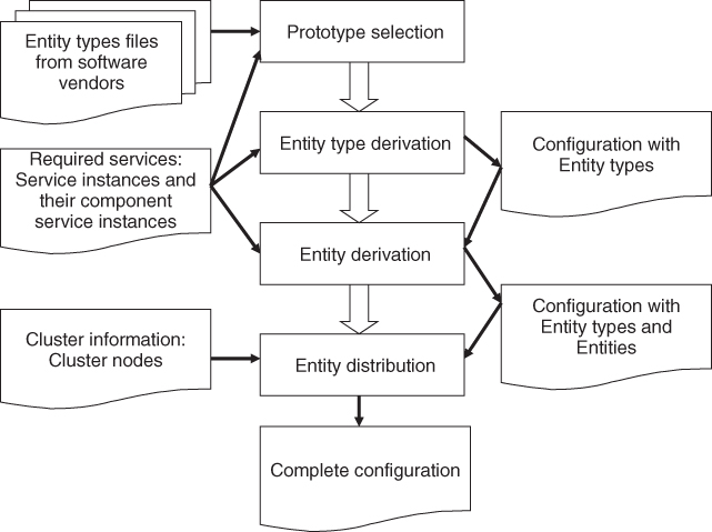
Figure 16.2 illustrates the different steps in the configuration generation process with their respective input and output.
Figure 16.2 Overview of the configuration generation process.
16.3.2.4 Implementation Options
The general principles of the configuration generation have been implemented within the MAGIC project in different ways. Both cover the AMF portion of the information model.
The first approach is algorithmic and it has been presented in more details in [123, 124], while specifics on SU ranking attributes settings is discussed in [80, 125].
The proposed solutions were implemented as Eclipse [126] plugins.
The basic principle in this solution is that given the input requirements the implementation searches through the ETF model to find the appropriate prototypes. Once a prototype has been found for the required CSI or SI he search moves on to the next until there is a selection for each of them.
A completely different approach is reported in [127], which is based on UML profiles defined for ETF and AMF and which fully exploits the MDA paradigm using the model transformation techniques. Rather then defining a selection algorithm, it defines the transformation rules that gradually mutate the model instances provided as input to the configuration generation to an instance of the output model.
The transformation rules are implementations of the relations between prototypes, types and entities and among the elements of each of these groups as we presented in the previous sections. They create links among the model elements if they satisfy the rule and prune the rest of the model. Applying the rules one by one to the input models eventually we reach the output model, which is constructed only of elements that satisfied all the applicable rules.
This declarative method has been implemented within Eclipse using ATLAS Transformation Language (ATL) [128].
16.3.3 Upgrade Campaign Generation
When it comes to upgrades we can talk about two main approaches: replacing the running entities with their new versions and migrating the system to a newly generated configuration.
In this section we look at each of these in more details.
16.3.3.1 Upgrading the Running Entities
This first approach is quite straightforward and used in most systems today. It is based on the fact that we usually want to upgrade the system or some parts of it when new versions of the running software become available.
Accordingly, the goal is to identify the entities running the old version of each of the software for which a new version is ready for deployment; and replace the old software with the new one by installing it and adjusting the configuration attributes then restarting the entity so that it starts to run the new software.
In Section 16.3.2 we have seen that entity types are derived from the entity prototypes describing the software implementation, that is, the entity type represents a particular software implementation. At the discussion of the AMF information model in Chapter 6 we also saw that entity types are grouped into entity base types as the reflection of different versions of the software delivering the same basic functionality.
This relationship puts in relation a new version of the software with those running in the system. Thus, it helps identifying the entities in the system which are upgradeable.
Of course, becoming upgradeable does not necessarily mean that we have to or want to upgrade the entities. Moreover, the upgrade of one entity may require the upgrade of other entities. Related entities need to remain consistent after an upgrade. Therefore the choice may depend on other factors and we may want to make a selection.
Once we identified the entities we would like to upgrade we can create a new configuration by replacing the entity types of the selected entities with the new entity types. It is essential that we validate this newly created configuration, for example, using UML CASE tools and the appropriate profiles because when we change the type of an entity its characteristics change, so may its dependencies and limitations. Many of these dependencies and restrictions are reflected in the relations of the different configuration attributes. While probably one can spot such a dependency change when the new version of a proxied component type becomes SA-aware. But when the change is as subtle as the modification of the component capabilities or the number of entities in a compound entity type, it may be difficult to find the difference. Both cases may render the modified configuration invalid without further modification of the configuration.
If the new target configuration evaluates as valid we can start the upgrade campaign generation. Existing entities that are part of a redundancy schema typically can be upgraded by a rolling upgrade procedure without causing any service outage. Therefore we can generate a rolling upgrade procedure for each service group whose SUs or some components within being upgraded.
To deal with the problem of the proxy becoming unnecessary by changing the proxied component type to an SA-aware type, we also need to be able to remove entities from the configuration. Symmetrically we would like to be able to add entities to the system.
The SMF specification suggests the use of single-step upgrade method in both cases. This suggestion is valid from the perspective of the services being added and removed. Unfortunately the operation is not performed in the vacuum, software installation, and removal, the dependencies between the entities and/or their grouping may impact other entities in the system beyond those being targeted by the upgrade campaign. In such cases we may want to generate a series of single-step upgrade procedures based on the redundancy of the impacted entities so we can make sure that the scope of each single-steps is not service impacting.
Figure 16.3 summarizes the upgrade campaign generation process.
Figure 16.3 Upgrade campaign generation for adding new, removing, and upgrading existing entities.
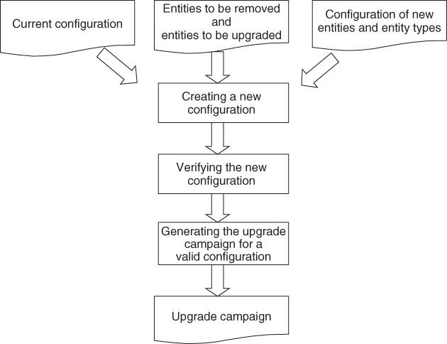
To reduce the overall execution time of the upgrade campaign the different procedures may be further grouped so that operations on the same node, for example, are collected together and the entire node is upgraded in a single step rather than locking and unlocking it multiple times.
An implementation of this semi-automatic upgrade campaign generation method composes the core of the work presented in [129], which has been implemented as an Eclipse plugin.
16.3.3.2 Upgrade to New Generated Configuration
We have seen the problem of the type replacement method: the new version of the type may not fit properly into the old configuration. Additional changes may be required, which may or may not be straightforward.
Also, since the running configuration was generated with the features of the old entity prototypes it possible could not take into account any new features of the newly delivered one, while the whole idea of the upgrade usually focuses on deploying those new features. A better idea is to generate a new configuration with the updated input requirement and upgrade the system to this new configuration.
Unfortunately it is easier said than done. The problem is that when we generate a configuration we generate the entity types and the entities including their names. Since the upgrade is about to change the characteristics of the entities, we cannot rely on them either to identify which entity is new in the system, which one was upgraded and which ones were removed. This mapping between the configuration of the running system and the newly generated system is the key element from the perspective of maintaining the continuity of the services.
This issue normally does not come up in systems that we can shut down and bring up with the new configuration. To maintain the continuity of the service we need to know exactly which entity participates in the redundancy for the provisioning of which service so that this redundancy can be used to avoid service outage.
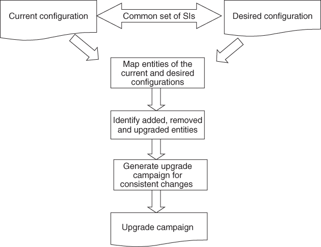
The continuity of the service seems to be the problem, but it also provides us with the solution: as we have seen in Section 16.3.2.1 one of the input requirements for configuration generation is the description of the SIs and their component service instances. All those service instances existing in the current configuration that need to be provided continuously throughout the upgrade and afterwards need to be part of the input requirements for the new configuration generation. This means that they put in relation the entities providing these service instances in the existing and the new configuration therefore we can resolve the mapping between the running configuration and the new one.
The mapping identifies three groups of entities:
- Entities to be removed: These are the entities that exist in the current configuration but do not map into any entity of the new configuration
- Entities to be added: These are the entities that exist in the new configuration but do not map into any entity of the current configuration
- Potentially upgraded entities: These are the entities that map between the current and the new configuration. These need to be analyzed further to find out whether they indeed have been upgraded.
Entities of the first two groups are always part of the upgrade target, while from the third group only those entities that changed some of their properties become part of the target. This information resembles the input for the upgrade campaign generation method presented in the previous section.
The differences are in the nuances. For example, it may occur that two service instances that are protected by the same service group in the current configuration, may be assigned to two different service groups in the new configuration. While in the previous process there was no way to specify such a change, the configuration generation method may create such differences. It may also select a different redundancy model to exploit the new features of the new software, which may not easily transform into an upgrade procedure.
Figure 16.4 summarizes the generation of an upgrade campaign that deploys a new configuration. Compared to Figure 16.3, there is no need for configuration validation since one can assume that the desired target configuration is valid. As not all changes may be consistently deployable while preserving service continuity we need to analyze the changes and may want to generate the campaign only if all the changes are consistent.
Figure 16.4 Upgrade campaign generation to deploy a new configuration.
This approach while it is more generic requires further investigation. The results achieved so far as part of the MAGIC project are reported in [130] including a prototype implementation as an Eclipse plugin.
16.3.4 Analytical Models and How They Can Help
In this chapter so far we have looked at the ways satisfying the requirements posed by the SA Forum specifications at automatic generation of valid configurations, upgrade campaigns and at the validation of third party configurations.
These specification requirements are related to the techniques offered by the SA Forum to increase the availability of the different services through the different fault tolerance mechanisms.
While the specifications pose many requirements in regarding the correct use of the specified techniques none of them are non-functional requirements and therefore do not characterize SA, which is the main subject of our book.
So the question is do we know what availability guaranties we achieve when deploying these techniques? This is the realm of fault forecasting as introduced in Chapter 1. We need to pose this question mainly for efficiency reasons: Since redundancy means extra cost we want to deploy just enough of it to meet our targeted availability since that is the level for which the customer is willing to pay.
Without attempting to give an exhaustive overview of the state of the art, we can say that the quantitative analysis of the availability of systems is based on the state models which describe the transitions of the system between healthy and faulty states. Failures that move the system to a faulty state may occur at different rates, while the repairs that move it back to a healthy state take some time and therefore characterized by durations.
To deal with the erratic nature of failures, stochastic models such as the Markov models [131, 132] have been developed early on and used for availability analysis. The Markov reward model is an extension of the Markov model, which allows the association of a reward rate with each state of a Markov chain, thus capturing nonfunctional aspects of the system such as performance and dependability.
Markov models are capable of representing complex real time system, however the number of states required doing so may be forbiddingly high [131] for manual processing.
An alternative model is the Stochastic Reward Net (SRN) [133], which is an extension to the Stochastic Petri Nets. It can represent the system in a still manageable size while it can be transformed automatically, for example, into Markov reward models which in turn can be solved analytically with available tools like stochastic Petri net package (SPNP) [134].
More recent work focuses on even higher level representation of the system using, for example, the already mentioned DAM [122] profile. In turn these higher level representations are also transformed into stochastic models for analysis, into Deterministic and Stochastic Petri Nets (DSPNs) in case of DAM.
Some work has been done with respect to the SA Forum specification as well: [135] presents the use of SRNs for SA computation.
All this would suggest that we should be able to answer the question what availability guarantees an SA Forum compliant system can provide. It turns out that this is not quite the case.
The AMF chooses a recovery action based on three factors among which the configuration, that is, the model – similar to those used by the discussed methods – is only one. In addition AMF takes into account the recommendations of the processes reporting the error and it also correlates the error with previous errors. All these may escalate the actual recovery recommended for a component to a recovery on the fault zone of a higher level.
This dynamic adaptation of the recoveries makes it hard to evaluate the availability of the AMF managed services. Hence the failure rates and the repair durations typically measured for the components in some test environment need to be re-interpreted for each new configuration, each new context the component is placed in. This means that components running the same software but on different nodes of the cluster may undergo different recovery actions and at different rates due to the impact of their different environment. The most tangible example for this is the software running on an overheating board.
All that is to say that a high level model discussed in Section 16.3.1 is a starting point for the evaluation of the availability and other non-functional characteristics, however the specifics of the transformation of this model into stochastic analytical models requires some further research.
When these results become available, they can be integrated into a configuration generation method as well as into the upgrade campaign generation to ensure that the outcome of the generation meets targeted non-functional requirements as well as compliant to the specifications.
16.4 Conclusion
This chapter addressed the missing pieces necessary to operate a system compliant to the SA Forum specifications: Namely, the creation of system configurations and upgrade campaigns deploying them. The AMF and the SMF cannot perform their respective task without these artifacts, but creating them for complex systems is a challenging task without tool support. To be able to provide tool support at least some formalization is necessary.
That is, we need a formal model to represent configurations. We looked at the SA Forum information model and in particular at its AMF portion to determine that in the form it is specified in the specification is suitable for runtime management, but for analysis one may benefit from further refinements, extensions, and formalization. One of the techniques suggested is the definition of a UML profile, which then can be used in UML CASE tools to support site designers in defining valid configurations and validating existing ones before their deployment.
One may go even further and relieve designers all together from the details of the AMF configurations by defining rigorous methods and techniques for the automatic generation of such configurations. We presented its principles and most important steps and pointed to two different approaches that have been implemented for this purpose.
The enabler for these techniques was the SMF, which requires software vendors to describe their software formally, so that this description is machine processable.
SMF also formalizes the specification of upgrade campaigns to be used to deploy a new configuration in a running system while maintaining SA. We have looked at the main challenges and the steps of coming up with an upgrade campaign. Since the goal is to maintain SA throughout the execution of the upgrade campaign we suggested the use of these services as the basis for the mapping of generated configurations to be able to identify the upgrade target. The upgrade target, in turn, determines the applicable upgrade methods based on which the upgrade campaign can be constructed.
Finally we looked at whether we could predict the SA achievable by a given configuration. For decades different stochastic models have been used for this purpose, but such analysis models capture different perspectives than the UML-based models used nowadays for system specification. Nevertheless there are solutions to transform these UML-based specifications into stochastic models to bridge the gap and allow for the evaluation of availability of the systems under consideration.
The SA Forum specifications include some features that require modifications/extensions to the existing transformation techniques, but there is no reason to assume this would be impossible.
It is desirable to go even further and based on the results of the analysis study to refine the configuration generation techniques to incorporate the lesson learned in the generation process itself so that the generated configuration meets an availability (and potentially other) nonfunctional criteria as well as the functional criteria imposed by the SA Forum specifications.
Throughout our discussion we referenced work that has been done in the area and we invite the interested reader to explore further the subject as here we only had the chance to give a taste to this work.
Complex systems such as grids and clouds cannot be operated without adequate tool support. One of the biggest challenges of clouds is already SA, which in turn requires proper design for manageability and maintenance. It is unimaginable to perform these tasks without appropriate tools that can provide provable guarantees of the design.
1 A Collaborative Research and Development project between Ericsson Software Research and Concordia University partially funded by the Natural Sciences and Engineering Research Council of Canada.