
Chapter 6
Model Based Availability Management: The Availability Management Framework
6.1 Introduction
This chapter introduces the Availability Management Framework (AMF) [48], which is the key enabler for achieving service availability (SA) with SA Forum systems.
The chapter focuses on the main aspects that are essential for understanding AMF and it is based on the general availability concepts introduced in Chapter 1 of the book.
In particular, this chapter introduces first the perspective that application developers will face, the concepts of components and component service instances (CSIs), their interpretation and how they are exposed through the AMF application programing interface (API).
This is followed by the view of the AMF on these same concepts and their organization into a hierarchy of logical entities composing the AMF information model which forms the basis for the availability management performed by the AMF. This is also the view that site designers, site administrators need to understand as the information model is the interface through which AMF is instructed what it needs to manage, that is, the AMF entities and their features composing the system and the different policies applicable during the management such as the applicable redundancy, the error detection mechanisms, and the error recovery policies.
The information model also provides status information on the health and readiness of the different entities to participate in the service provisioning. The AMF itself uses this information to distribute the role assignments for this service provisioning among the different entities. This in turn is also reflected as state information that reflects the role the different entities take in this task and also as the status of provisioning for the services.
The different redundancy schemas that can be used in conjunction with the AMF demonstrated on simple examples of single-failure scenarios to provide an easier grasp on them as they are one of the key concepts of AMF. They also demonstrate the wide range of availability needs that can be covered by the AMF.
A significant part of the chapter discusses the administrative operations applicable to different AMF entities and their impact in the system. Finally the interactions between the AMF and other Application Interface Specification (AIS) services are summarized.
Considering the size of the specification this chapter cannot embark on an in depth presentation and analysis of AMF. So the main goal we set out was to try to convey to the reader the logic behind the solutions provided by the specification. To teach the way of thinking about availability management as we see this is an easier way to grasp this complex subject.
Probably the most ingenious steps in defining a standard for availability management was the abstraction from the services as perceived by ‘end-users.’
An end-user is interested in the functionality and performance of the service, while the AMF abstracts from these aspects and defines services as units of workload that can be assigned to some provider entities in order to provide or protect the end-user perceived functionality. The AMF service instance (SI) concept is the control mechanism used by AMF similar to the way a faucet knob is used to control the water flow—the SI being the knob and the water the end-user perceived service.
In addition these SIs are also logically separated from the entities that are providing them, allowing AMF to move around the SI assignments as an independent entity for which then the continuity is based on the existence of the appropriate assignment.
The logical organization of the entities and their state models, the policies and schemas defined in the specification all serve this single purpose: to maintain the appearance of this service continuity; and as long as a user can initiate successfully a service request this attempt is successful and SA is provided.
After a short overview that links the AMF concepts to the basic concepts of fault tolerant systems discussed earlier in this book we will embark on our adventure of familiarizing the AMF.
6.2 Background
Chapter 1 has introduced the difference between fault, error, and failure. One may realize that from the perspective of SA, availability is only affected when an error manifests externally as a failure. This means that there is a window of opportunity for availability management to detect an internally manifested error and take some corrective measures to prevent the externally manifested failure to happen or at least to lessen its impact. This window of opportunity lasts from the moment a fault is activated until its external manifestation; and within this period the earlier one is able to take the corrective actions the lesser is the service impact, it may even be avoided completely.
6.2.1 Error Detection and Repair
The prerequisite of early intervention is the early detection of errors. This means that the AMF must provide tools appropriate for error detection. As we will see in the subsequent sections the specification indeed includes a range of tools that follow today's best practice in error detection. The different options suit different circumstances. The AMF uses some of them in all cases, while others are configured and activated on request. These different techniques can be tailored for different AMF managed applications depending on their capabilities and needs in the particular circumstances of a deployment.
Once it has detected the error, the AMF takes actions to correct the situation. These actions have three distinct goals:
- Most importantly they provide fault isolation, so that the fault cannot propagate any further.
- Secondly they repair or replace the faulty element to return the system to the healthy state.
- Finally, if the faulty element was providing some services the actions try to restore those services.
A particular corrective action may achieve more than one of these goals. For example, a restart of some faulty software isolates the fault as it removes the faulty element from the system. At the same time it also repairs the element as at the completion of the restart a new healthy element becomes available.
Note that healthy in this case is relative as restarting the software does not eliminate any bugs from it. As earlier chapters indicated, it is essential that the software is sufficiently tested before deployment in such systems and it fails only under somewhat peculiar circumstances. The availability management cannot eliminate software bugs and other faults in the ‘workmanship’ permanently.
The AMF relies on the termination of a managed entity for fault isolation and after successful restart it considers the entity healthy again. This implies that the AMF is in charge of the life-cycle of the entities it manages.
6.2.2 Fault Zones and Error Escalation
The problem is, however, that faults may or may not manifest in the faulty entity. For example, a memory leak caused by one process may cause the malfunction or failure of another independent process and the error is detected in this innocent second process.
In such cases obviously the termination and restart of the second malfunctioning process neither isolates the fault nor repairs the first process at the root of the problem. It only isolates any derivate fault propagated to the second process in which the fault manifested and repairs the second process, more precisely the logical entity represented by the second process (as after the restart we cannot talk about the same process instance any more).
To deal with this issue of fault propagation, the AMF defines an incremental set of fault zones that encapsulate more and more entities based on the expected fault propagation. This allows the definition of escalation policies to a wider fault zone if repeated errors are detected within some probation in this encapsulating fault zone. Accordingly, a successful restart becomes a successful repair only after this probation period.
Using our example of the memory leaking process, this means that since the first process capable of propagating its fault to the second they are put in the same wider fault zone, which also becomes under suspicion with the detected error. The successful restart of the malfunctioning second process does not complete the fault isolation and repair for this wider fault zone. Instead, it starts a probation timer for it. While this timer is running, AMF considers all errors detected within this fault zone related.
This means that if either of the processes fails during the probation period, the error is escalated to the entire fault zone and AMF will terminate and restart both of the processes. This allows us to deal with the root cause of the problem, with the faulty process regardless whether any error was detected in it or again it impacts its neighboring process.
The AMF information model reflects these incremental fault zones as we will see in Section 6.3.3 and it forms the basis for the implementation of the error escalation policies.
Obviously while AMF is terminating and restarting a process or the encapsulating fault zone none of the enclosed entities can provide service, which in turn adversely impacts our main goal of providing highly available services.
It is often desirable to have some replacement entities readily available in the system, which then can take over the service provisioning as soon as the faulty entities have been isolated from the system. Hence as discussed in Chapter 1, redundancy is the standard solution for this problem and it has been widely used in systems that require any level of availability. The AMF specification follows the same general solution, but in a somewhat special way that may be hard to grasp on first read.
6.2.3 Separation of Services from Serving Entities
The distinctive feature of the SA Forum's AMF is that it logically separates the entities providing the service from the services they provide.
Let's consider an application implementing an alarm clock. As one would expect when the alarm clock is started it is set for the time it should raise the alarm. From this moment on the process will compare the current time with the time for which it is set and decide whether it is time to raise the alarm. If the process fails by any reason before the set time and if we are able to replace it with a new process for which the same time is set, we will be able to raise the alarm at the requested time and fulfill the requested service.
Thus, the failure of the process providing the service does not mean the failure of the service itself and another process receiving the same service assignment can complete the task. This justifies the separation of the service from the entity providing the service.
Furthermore, the same alarm clock program can be started multiple times with different time settings which will result in multiple processes, each providing its own alarm service, each of which could be considered as a different SI. Even if we start two processes with the same time setting, they will each raise the alarm separately and distinguishably, so there are still two different instances of the service. On the other hand giving the same time setting to two consecutive processes—as we discussed above—creates the impression of service continuity for the service user as the alarm will be raised only once.
From these considerations, the AMF distinguishes service entities and service provider entities. Service provider entities are organized in a redundant way to provide and protect the nonredundant service entities.
Note that failure may occur in both service provider and service entities; however, the failure of a service provider entity is considered as an internal manifestation of a fault, that is, an error as long as there is another service provider entity that can take over the service provisioning from the failed provider. Only if there is no available service provider entity that can take over the service provisioning can we consider the failure as a service impacting external failure.
The action of taking over the service provisioning from a failed entity is referred to as failing over the service from the failed entity to the new provider entity, or fail-over for short.
6.2.4 Service Provisioning Roles
At this point we need to look at the service from a user's perspective. Considering the alarm clock implementation, it is easy to see that no matter how many times we need to replace the alarm clock process by failing over the service to the next available process, we can do so successfully using the same initial data—the time at which the process has to raise the alarm. As long as there are no two processes running at the same time with this same time assignment, the service will be provided exactly once regardless whether the availability manager is aware of the actual meaning of the service and its status as seen by the service user.
Now let's consider instead of this alarm service another application which implements the stopwatch service. Again when a process is started it starts to measure the time, however, to be able to replace a failed process without service impact the replacing process needs to know the elapsed time the failed process measured and be able to continue the counting as increment of this initial value. Without this even if we are able to replace the process providing the service, the delivered to service user result will not be flawless.
One of the solutions is that we assign two processes to the task from the beginning, but with different roles. One of the processes plays a primary role and actively delivers the service, while the second stands by and regularly synchronizes the measurement of the elapsed time with the first one in case it needs to take over the service provisioning. In this setup the user of the stopwatch service interacts only with the active process. The user is not aware of the existence of the second process. If the user suspends or stops the timer, it is the active process that informs its peer standby process about these events.
Notice that in this solution it is enough if the processes know their responsibilities depending on the role they have been assigned. The AMF does not need to be aware of any of the user aspects of the service provided by the application. It only needs to coordinate the roles the different processes play in the provisioning of the service, monitor their health, and if any of the processes fail reassign the roles and repair the failed entity by restarting it.
Obviously the application now needs to be prepared to handle these different roles. This raises several questions ranging from the benefits of using the AMF to the appropriate synchronization that needs to be implemented between these peer processes.
6.2.5 Delicacies of Service State Replication
If there was no availability manager to use, the application would need to include a part that monitors the health of its different parts. While this is relatively simple when only two redundant entities provision a single service in an active-standby setup, it becomes more complicated when other considerations are taken into account. For example, the active-standby setup always means 50% utilization as one of the entities is there just in case it needs to take over; until this, it does not provide any service.
When we have relatively reliable entities, this may be a huge waste of resources and we may want to have one entity acting as standby for many others. In other cases when, for example, the recovery is long and the service needs to be very reliable, one standby may not be enough and we may want to have multiple standbys.
From the service provisioning aspect all these scenarios mean the same:
- acting as an active and provide the service; or
- acting as a standby and protecting the service whatever that means for a particular service; and
- switching between the roles as necessary.
It is the coordination of these roles which is different for the different scenarios; however this coordination does not require any knowledge of any of the user aspect of service. This is the reason why the AMF was defined and its specification incorporates a wide selection of redundancy models that application designers or even site designers may use. Note that since the application relying on AMF's management only needs to implement a well defined set of states and state transition which apply to most of the redundancy models offered by the AMF, the actual selection of a particular redundancy model can be postponed till the moment of deployment and therefore tailored to the concrete deployment circumstances.
The question is whether it would be possible to eliminate even this need for the application's awareness about the redundancy.
As we have seen in the case of the alarm clock service, since the service did not require any state information additional to the initial data, there was no need even to assign a role to the process protecting the service. However, in the case of stopwatch service there is hardly any way around for providing service continuity than synchronizing the standby with the active process, so it is aware of the current status of the provided service.
We can see that there will be always a class of applications that have some state information which needs to be transferred to the standby in order to provide the impression of continuity for the service user.
This means that to release the application from the awareness of this state synchronization requires that an external entity provides some mechanism for the state replication. The problem is, however, that as soon as state replication is done outside of the application's control the ‘replicator’ cannot judge the relevance of the information, so it needs to be a complete state replication, otherwise information important for the application may be lost. Unfortunately this opens up the fault zone: The more state information is copied from a faulty entity to a healthy one, the more likely it is that the information encapsulating or manifesting the fault itself will be copied as well, which in turn corrupts the standby entity.
There is a delicate balance between state synchronization and fault isolation.
The AMF, however, does not deal with this aspect of state synchronization between active and standby entities. It was defined so that it only coordinates the roles between the redundant entities protecting the service and it is left to the application to decide what method it will use for the state synchronization. It may use databases or communication mechanisms for this purpose; however, general purpose solution may require adjustments to the clustered environment (e.g., to achieve location transparency).
There are a number of AIS services that address these issues. The service targeting exactly this need is the Checkpoint Service [42]. It allows its users to define cluster-wide data entities called checkpoints that are maintained and replicated by the service and that an application can use to store and replicate state information so that it becomes accessible across the cluster. Services providing location transparent communication mechanisms within the cluster can also be used to exchange state information between entities. We will review these different services in Chapter 7.
In this chapter we continue with the overview of the AMF as defined by the SA Forum, introduce its terminology and elaborate more on the solutions it offers to the different aspects of availability management we have touched upon in this section.
6.3 The Availability Management Framework
6.3.1 Overview of the SA Forum Solution
As we have seen previously the tasks associated with availability management can be generalized and abstracted from the functionality of the applications themselves. On the one hand, this makes the application development process shorter, simpler, and focused on the intended application functionality. On the other hand, this requires an appropriate well defined availability management solution that application developers can rely on.
Such a generic availability solution is offered by the SA Forum AMF specification [48]. It defines an API that application processes should use to interact with an AMF implementation and an information model, which describes for the AMF implementation the entities it needs to manage and their high-availability (HA) features. At runtime it also uses the information model to reflect the entities runtime status. In addition for operational and maintenance purposes, the specification defines the management interface in terms of administrative operations AMF accepts and notifications AMF generates.
Within an SA Forum middleware, the implementation of the AMF specification is the software entity responsible for managing the availability of the services offered by applications running on the SA Forum middleware implementation. From this perspective, the AMF interfaces are the only way the middleware can impose availability requirements toward the applications it supports; therefore only the services provided by applications integrated with AMF are considered to be highly available services.
To understand how the SA is achieved by AMF we need to look deeper into the functionality of the AMF. However, it is very important to understand that an application developer does not need to deal with or even understand all these details to be able to accomplish his or her task of writing an application to be managed by AMF to provide highly available services. Much of the AMF functionality is hidden from the application, which only needs to implement appropriately the API and the states controlled via the API. Similarly, most parts of the AMF information model are also irrelevant for application developers.
The information model is important for site designers or integrators as it is the main interface toward AMF from their perspective. It is the means by which they describe for an AMF implementation what entities compose the system that it needs to manage and what policies apply to those entities.
Finally site administrators need to understand the information model as AMF exposes the state of the different entities through the objects in the model and their attributes. Administrators can also exercise administrative operations on the subset of entities for which such operation have been defined. In addition, they also need to have a general understanding of the consequences different events and actions may cause in the system and the notifications and alarms AMF generates that may require their attention. This chapter provides an insight into these different perspectives.
Let us now dive into the depth of availability management as defined by the SA Forum AMF specification.
6.3.2 Components and Component Service Instances
The only entities visible through the AMF API are the component and the CSI. They represent the two sides distinguished by the AMF as discussed earlier: the service provider side and the provided service side. Since they are visible through the API, application developers need to understand these concepts. In fact these are the two concepts that AMF managed applications need to implement.
So what are they: the component and the CSI?
6.3.2.1 The Component
The component is the smallest service provider entity recognized by the AMF. It can be any kind of resource that can be controlled directly or indirectly through the AMF API or using CLI (command line interface) commands. Components can be software resources such as operating system processes or Java beans or hardware resources such as a network interface card as long as there is a way for AMF to control them by one of the above methods or their combination.
We can distinguish different component categories depending on the method AMF controls them. We will look at them in due course (see Section 6.3.2.5). For the time being we will focus on the simplest component that implements the AMF API, which is referred as a regular SA-aware component.
A component may encompass a single or multiple processes, or in other cases a single process may encapsulate a number of components. In general, however, we can say that there is always one process which is linked to the AMF library and implements the AMF API. It also registers the component with the AMF.
This process is responsible for the interaction between AMF and the component the process represents. Note that this allows the process to represent more than one component, therefore the API ensures that it is always clear which component is the subject of any interaction through the API.
The decisive criterion on what constitute a component is the particularity that it is also the smallest fault zone within the system. If any part of a component fails AMF fails the entire component and applies fault isolation, recovery and repair actions to the entire component. This means that the component boundaries need to be determined such that they provide adequate fault isolation, for example, fault propagation through communication is kept to the minimum. At the same time it is desirable to keep the disruption caused by these recovery and repair actions also to the minimum, that is, to keep the component small enough so it can be repaired quickly, particularly if such repair is needed relatively often. A car analogy would be the spark plug; we want to be able to replace the spark plug whenever it becomes necessary and not define the whole engine as a single undividable component.
6.3.2.2 The Component Service Instance
The reason of having the components in the system is of course that they can provide some services we are interested in. The AMF is not aware of the service itself a component can provide, it is only aware of the control mechanism that allows the management of the service provisioning. This is what the CSI is defined for. It represents a unit of service workload that a component is capable of providing or protecting.
For example, a component may be able to provide some service via the internet and therefore it expects an IP (internet protocol) address and a port number as input parameters to start the service provisioning. By assigning different combinations of these parameters different instances of this internet service will be created. They represent different workloads as users knowing a particular combination will be able to access and generate workload only toward that one component serving that particular combination.
Hence, one may also interpret the CSI as a set of attributes that configure a component for a service it is capable of providing. By providing different configurations, that is, different sets of input parameters, different CSIs can be provisioned by the same component.
Some components may even be capable of accepting these different configurations simultaneously and therefore provide multiple CSIs at the same time. Others may not have such flexibility. Some components may be able to provide more than one type of service, each of which would be configured differently.
The AMF abstraction from all this is the CSI. It is a named set of attributes that AMF passes to the component through the API to initiate the service functionality the CSI represents, that is, to assign the CSI to the component.
AMF does not interpret any of these CSI attributes; they are opaque to AMF. The same way the actual service functionality they initiate is also completely transparent for AMF.
The component receiving the assignment from AMF needs to be able to understand from the attributes themselves what service functionality it needs to provide and its exact configuration.
AMF uses the CSI name passed with the attribute set to identify this combination of service configuration. The CSI name, however, is not known at the time the software implementing the component is developed. If another component receives the same named combination of attributes, it should provide the exact same service functionality indistinguishably to the service users.
Hence we can perceive the CSI as a logical entity representing some service provisioning.
It is interesting to note—and this further explains the difference between the user aspect and the availability management aspect of the service—that from the perspective of the service user a completely different software may be able to provide exactly the same service (let's say this internet service mentioned), but a component running this software may require a different set of attributes (e.g., an additional parameter is needed that the service to be provided is ftp—as it can also provide ssh). Since the CSIs need to be different for each of these components, AMF will see these as CSI of different types. One composed of two the other of three attributes regardless that the user will receive the same ftp service.
It is also true that the same set of CSI attributes when they are assigned to different components may result in different services as perceived by the user. Many internet services require the address and the port as input parameters. AMF, however, will perceive these as different CSIs if these attribute sets are associated with different names regardless of whether the attribute values are the same or not. If they could have the same name then AMF would handle them as the same CSI and therefore the same associated service functionality. This however is not permitted.
6.3.2.3 Component High Availability State
To achieve HA we need to introduce redundancy on the service provider side, so in addition to service provisioning we also protect that service. Translated to the AMF concepts learnt so far this means that we need multiple components assigned to the same CSI at least one of which is actively providing the service while at least one other stands by in a state that it can take over the service provisioning in case of the failure of the first one. In the assignment the roles of these two components need to be distinguished. The AMF accomplishes this through defining different HA states in which a CSI can be assigned to a component.
As a minimum we need to distinguish the active assignment from the standby assignment; that is, when a component receives an active assignment it must start to provide the service functionality according to the configuration parameters indicated in the CSI assignment. When a component receives the standby assignment for the same CSI, it must assume a state that allows a timely takeover of the service provisioning from the active component should it become necessary. It should also initiate any functionality that keeps this state up to date. This typically requires state synchronization with the component having the active HA state assignment for the same CSI; therefore when AMF gives a standby assignment to a component, it always indicates the name of the component having the active assignment for the same CSI. Based on this information, the component must know how to obtain the necessary information and maintain this state.
The AMF does not provide further means for state synchronization and other methods; for example, other AIS services such as the Checkpoint Service can be used to achieve this goal.
Having active and standby assignments for the same CSI is sufficient to handle failure cases. If the component having the active assignment fails AMF can immediately request the component having the standby assignment to assume the service provisioning starting from the latest service state known by the standby. At this point since the active component is known to be faulty, any interaction between the active and the standby components including state synchronization is undesirable. Note that this may mean the standby lagging behind depending on the frequency and used state synchronization mechanism between the active and the standby components. This may even mean a service interruption from the perspective of a particular service user, for example, a call or a connection may be dropped as a result. All this depends on how up-to-date the standby is at the moment it receives the active assignment.
The term for this procedure is CSI fail-over.
There are cases when we would like our components to change roles. For example, we may have received an update of our software and we would like to upgrade our components. We could do this by upgrading one component at a time, which means that we would like to be able to transfer the assignment between the components so that this results in the absolute minimum service disruption. To achieve this we would like to force a state synchronization between the components assigned active and standby for the CSI at the time of the role transfer.
For this purpose AMF defines the quiesced HA state.
It is always the component having the active assignment which is requested to assume the quiesced state by suspending the provided service functionality and holding the service state for the component having the standby assignment. As soon as the component confirms that it has assumed the quiesced state for the CSI, AMF assigns the active state to the component currently holding the standby assignment. In the assignment AMF also informs the component taking over the active role about the availability of the now quiesced former active component for the CSI. As part of the transfer the component assuming the active role should obtain the current service state from the quiesced component (directly or indirectly) and resume the service provisioning. When this is completed and the component confirms the takeover to AMF, AMF can change the HA state for the CSI of the other component from the quiesced to standby (or if needed the assignment can be completely removed without service impact).
This procedure of exchanging roles between components is called component service instance switch-over.
Note that even though we used the expression ‘quiesced component’ it needs to be interpreted as ‘the component assigned the quiesced HA state for the CSI’ as for other CSIs the component may maintain other HA state assignments.
The AMF defines different component capability models depending on the number and the variation of HA states a component is able to maintain simultaneously. If a component is capable of providing different types of services, each of them can be characterized by a different component capability model.
The component capability model defines the number of active assignments and the number of standby assignments that the component is able to maintain simultaneously for different CSIs, and whether it is capable of handling active and standby assignments simultaneously. The component capability model is one of the most important characteristics the developer needs to specify about the software implementing the component. The list of possible component capability models is given in section ‘SU HA state’ where we discuss this feature in a wider context.
A different type of service suspension is necessary when we would like to gracefully terminate the provision of some service. Graceful termination means that users that have already obtained the service and are being served currently should be able to complete their service request. However in order to terminate the service we do not want to allow new users to be able to obtain the service by initiating new requests.
Let's assume an http service that we configure by giving the server's IP address and port number. From AMF's perspective this is a single workload as AMF uses a single CSI assignment to assign it to a component; but from the service user's perspective this workload is perceived as hundreds and thousands of service initiations each started by an http request and completed when the page is completely served to the user. In the active state the component would accept each request addressed to the IP address and port assigned in the CSI assignment and serve it till completion. These http requests arrive to this active component continuously. To gracefully terminate this service we want to let already initiated requests complete, but prevent the component accepting any new request. The AMF informs the component active for the CSI about this behavior change by changing the HA state assignment for the CSI to quiescing. This assignment also requests the component to inform AMF when it has completed the service of the last ongoing request. When the component completes the quiescing it is assumed that it quietly (i.e., without AMF instructing it) transitions to the quiesced state. In the quiesced state the CSI assignment can be completely removed or switched over as we have seen.
The quiescing state is a variant of the active state therefore it is protected by a standby assignment the same way the active assignment is protected. In cases when at most one component may have the active assignment this restriction applies to the quiescing state as well, that is, only one component may have the active or the quiescing state for a CSI at any given time.
To summarize the difference between the quiescing and quiesced states: quiescing counts for an active HA state assignment, quiesced does not; in quiescing the service is provided by the component for existing users, in quiesced the service is suspended for all users; as a consequence a quiescing assignment is typically protected by a standby assignment, while quiesced is the state protecting the service state during a state transfer.
6.3.2.4 Error Handling and Component Life Cycle
After the service provided by the component has been gracefully terminated, we may want to remove also the component itself from the system. AMF terminates the component using the API, namely using the terminate callback. The component receiving the callback should wrap up its actions as necessary for the service functionality (e.g., save any necessary data, close connections, etc.), terminate all of its constituents (e.g., child processes) and exit while confirming the completion of the operation to AMF.
Since the AMF defines the component as the smallest fault zone it makes the assumption that with the termination of the component the error that was detected in the component becomes isolated and removed from the system. This assumption contradicts the termination described above as it preserves some state and also it is performed via the API, which cannot be trusted any more.
For the termination of a component on which an error has been detected AMF uses tools available at the level below the component, for example, at the operating system level, which still can be trusted and which prevents any state preservation. It expects for a component executing on the operating system a so-called clean-up CLC-CLI (component life cycle command line interface) command, which when issued must abruptly remove all the constituents of the component from the system. It needs to prevent any fault propagation: The execution of the cleanup command must be as quick as possible to prevent any interaction with other components and must not preserve any of the service state information of the faulty component.
As we mentioned earlier, the service state synchronization between the active and the standby components counteracts to the intention of the component being a fault zone. This and any data exchange carries the risk of propagating the fault; they open up the fault zone. One has to take special care when determining the information exchanged even while the component is considered healthy. The exchanged data should be the necessary and sufficient amount as the lack of error does not indicate the absence of faults, it means only that a fault has not manifested yet so it could be detected.
As soon as an error has been detected any data exchange must be prevented immediately. Therefore AMF performs right away the cleanup procedure associated with the component—typically at the operating system level.
Once the component has been cleaned up to restore the system health the AMF will try to restart the component and if it is successful the component becomes available again.
All this means that besides managing the HA state assignments, AMF also controls the life-cycle of the components it manages. It initiates the component instantiation normally using the designated instantiate CLC-CLI command, which may, for example, start a process as the manifestation of the component.
Once all the constituents of the component have initialized and the component is in the state that it can take CSI assignments, one of its processes registers with AMF using the AMF API. From this moment on the component is considered available and healthy. That is, in general the successful re-instantiation of a faulty component is perceived as also a repair action. AMF may or may not assign a CSI to the repaired component.
Note that the AMF is not aware of the component and process boundaries. The registration creates an association between AMF and the registered process (represented by a handle) and AMF uses this association to identify or to communicate with a given component.
Since usually it takes some time to clean up a faulty component and instantiate it again, AMF fails over to their appropriate standby component(s) the CSIs that were assigned to the faulty component at the moment the error was detected. The successful assignment of the HA active state of the CSI to the component with the standby assignment recovers the service, so the CSI fail-over is a recovery action.
Failing over the assignment also takes some time. If we compare the time needed for these two operations the component restart and the CSI fail-over we may see that for some components actually the re-instantiation may take less time than the fail-over.
The CSI fail-over can only be executed after successful cleanup, otherwise it cannot be guaranteed that the faulty component indeed stopped providing the assigned CSI. Hence the cleanup is part of the recovery time regardless of the recovery method.
Restart may take less time in cases when failing over the assignment would mean significant data transfer to the standby component's location, which does not need to be performed if the component is restarted locally. For such cases the AMF includes the concept of restartable components.
If such a restartable component fails, the AMF first proceeds as usual with the cleanup of the component. But, when the cleanup successfully completes rather than moving the active assignments to the appropriate standby components, they are logically kept with the failed component:
AMF attempts to instantiate the failed component to repair it; and if it is successful AMF reassigns to the component the same CSIs assignments that it had at the moment the error was detected.
Consequently such a restart operation, which is executed as a cleanup followed by an instantiation, becomes not only the fault isolation and repair actions, but also the service recovery action.
The AMF performs similar fault isolation and repair actions on components that have no active assignment. In these cases there is no need for service recovery; however to replace a failed standby AMF may assign the role to another suitable candidate.
Components that have an HA state assignment on behalf of a particular CSI are collectively referred to as the protection group of this CSI.
Any process in the system may receive information from the AMF about the status of a protection group using the protection group track interface and referencing the name of the CSI in question. Depending on the track option AMF will provide the list of components and their HA state assignments that participate in providing and protecting the CSI. It will also report subsequent changes to this status information such as state re-assignments, addition, and removal of components to the protection group.
6.3.2.5 Component Categories
Component categories ultimately reflect the way the AMF is able to control the component life-cycle. Table 6.1 summarizes the component categories that have been defined for the AMF. The category information is part of the information model AMF requires for proper handling of components.
Table 6.1 Component categories
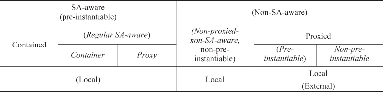
In the table we indicated in parenthesis implied categories deduced from other features. Italic indicates the main component categories we distinguish for availability management.
Except for the proxied components, components of all categories run within the cluster and referred as local components. Proxied components may run within the cluster locally or outside of the cluster externally.
As long as the component runs within the cluster (i.e., it is local), AMF can use system tools to instantiate, terminate, and cleanup the component. Essentially AMF can control any process by controlling its life-cycle through these CLC-CLI commands provided that the process when it is started it starts to provide its service immediately. Therefore such a process can be integrated with the SA Forum middleware even for availability management as an AMF managed non-SA-aware-nonproxied component.
The assumption is that such components do not implement the AMF API. They are also not aware of the HA states, therefore they cannot maintain an idle state after instantiation, which means that the AMF instantiates such a component only at the moment it needs to perform the active role and AMF terminates it as soon as the assignment needs to be withdrawn. The instantiation is considered to be a simultaneous CSI assignment operation; and similarly the termination is considered to be a simultaneous CSI removal operation. Consequently always a single CSI summarizes and represents all the services such a non-SA-aware-nonproxied component provides.
Note that the termination even though it is performed as a CLC-CLI command is a graceful operation and the component may perform any action required for the orderly termination of the service it provides.
We have mentioned already the category of components that implements the AMF API and therefore referred to as SA-aware. This also implies that they are aware of the HA states and after instantiation they are capable of staying idle without providing any service until AMF decides to assign to them a CSI assignment.
Depending on whether AMF can control directly their life-cycle, SA-aware components can be still of two kinds. When the component executes on the operating system accessible for AMF and therefore AMF can use the instantiate and cleanup CLC-CLI commands in addition to the terminate API callback, AMF is in complete control of the component's life-cycle. Regular SA-aware, container and proxy components fall into this group.
AMF cannot directly control the life-cycle of components that require an environment different from the operating system accessible for AMF. In this case, this different environment is considered as a container of such components. For this reason, the components executing in this special environment are called contained components and the environment itself is also a component of the container category. For AMF to manage the life-cycle of the contained components, the container in which they reside needs to act as a mediator. The container needs to implement a part of the API, which allows the instantiation and cleanup of contained components. In other words, the service that a container component provides is the functionality of mediation between AMF and its contained components and it is also represented as a CSI—the container CSI. Accordingly when AMF decides to use a container for some contained components, first it assigns the CSI associated with the mediation of those contained components to the container component. Only after this it will proceed with the instantiation of the contained components.
The container's life-cycle is also linked with the life-cycle of the contained components: The contained components cannot and must not exist without their associated container component. For example, if the java virtual machine (JVM) process is killed all the Java beans running in it cease to exist at the same time.
This means that if the container component is being terminated, all its contained components also need to be terminated. AMF orchestrates the termination via API callbacks as all these components are SA-aware. On the other hand, if the container is cleaned up, that implies that all its contained components are also abruptly terminated. The abrupt termination of contained components needs to be guaranteed by the cleanup CLC-CLI command of the container component as AMF has no other means to cleanup contained components when their container is faulty and cannot be relied on.
The last group of SA-aware components is the proxy. Proxy components perform a similar mediation on behalf of AMF as container components, but toward proxied components. In this case the mediated functionality goes beyond life-cycle control since proxied components are non-SA-aware components. Another difference is that the life-cycles of the proxy component and its proxied components are not linked. The termination of the proxy does not imply the termination of its proxied components, as a result for local proxied components the cleanup CLC-CLI command still applies and AMF may resort to it.
The AMF has no direct access to external proxied components or their environment. In fact AMF is not even aware of the location of such a component as it is outside of the cluster, the scope recognized by AMF. Such components can only be managed via a proxy.
Proxied components are also classified whether they are able to handle the HA states even though they are not implementing the AMF API. Components that are able to be idle, that is, provide no service while still be instantiated are pre-instantiable components just like all SA-aware components. For them AMF performs the exact same HA state control as for SA-aware components all of which is mediated by the current proxy.
This means that AMF requests the proxy component to instantiate such a proxied component regardless if it needs to provide services or not and when the instantiation completes the proxy component registers with AMF on behalf of the proxied component. Later when the proxied component needs to provide a service, AMF calls back the proxy component mediating for the component with a CSI assignment for the associated proxied component. The proxy needs to interpret this CSI assignment, initiate with the proxied component the requested functionality and inform AMF about the result. The HA state changes for the CSIs assigned to the proxied component and the component termination are similarly mediated.
Proxied components that are not aware of HA states, and cannot stay idle because they start to provide their services as soon as they are instantiated are non-pre-instantiable proxied components. This means that the AMF handles them similarly to non-SA-aware-nonproxied components except that it uses the proxy's services to mediate the life-cycle control.
Just as in the case of the container component the proxy functionality is the service a proxy component provides and it is controlled through a CSI—the proxy CSI.
A peculiarity of the proxy-proxied relationship comes from the fact that their life-cycle is independent. That is, the failure of the proxy has no direct implications on the state of its proxied component. It may or may not fail together with the proxy, it may even continue to provide its service. Without a proxy AMF has no information on its state. If we can make any assumption, it should be that the proxied component remains operating according to the last successfully mediated instructions.
So for the availability management of the proxied component it is essential that the proxy CSI associated with the proxied component is assigned and provided as the active proxy is the only means to maintain contact with and control the proxied component. When the current proxy component fails AMF will attempt to recover the CSI as appropriate, but during this time it has no control over the proxied component. When the newly assigned proxy re-establishes contact with a running proxied component it registers on behalf of the proxied component. Otherwise it reports any error it encounters.
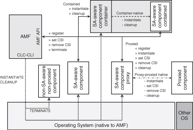
Figure 6.1 summarizes the different component categories and the interfaces AMF uses to communicate with each.
Figure 6.1 Component categories and related interfaces.
6.3.2.6 Error Detection
Reading thus far one should realize that the most important triggering event for the different actions carried out by the AMF is the detection of errors. So the question rises: how does AMF determine the health of the components under its control? How does it detect errors?
The obvious way of detecting errors is through the interaction with the component using the AMF API.
The AMF initiates most of the control operations by callbacks to the process which has registered itself on behalf of the component targeted by the operation. Whenever there is an error in this interaction, since the same process may register multiple components (e.g., a proxy) AMF correlates the component category information and the detected error to determine which one is the faulty component.
A component may respond to a callback with an error, or a faulty component may not reply at all. Both of these cases indicate an error for AMF and it should determine which component is the faulty one to be able to take the correct measures.
If the operation is not mediated—does not go through a proxy or a container—then no response reflects the failure of the component targeted by the operation.
If the operation is mediated (e.g., AMF requests the proxy to put its proxied component into active HA state for a CSI) then no response means the failure of the mediator component and not the targeted component (i.e., the proxy in the above case and not the proxied component).
If the AMF receives an error in response to the initiated operation then it interprets this as the component targeted by the operation is at fault.
A different type of interaction occurs when a component initiates an operation through the API. These operations must be in a particular order and appropriate for the state of the component. If an operation is inappropriate (for example, a component responds without being asked) the AMF deems the initiating component faulty and engages in the required recovery and repair actions.
Control operations occur in the system relatively rare and as we have seen they are typically already in reaction to some problem that has been detected. To continuously monitor the health of components, the AMF needs other solutions.
The first one is a special API dedicated for this purpose—the healthcheck.
Any process (and not only the registered process) may request AMF to start a healthcheck which means that the process will need to confirm its health at a regular interval either in response to AMF's inquiry or automatically by itself. If AMF does not receive such a confirmation at the expected time, it declares the component whose name was given in the healthcheck start request faulty and applies the recommended recovery action also indicated in the start request.
Note that the component name needs to be given at healthcheck start as AMF only knows about the association of the component with the registered process. Other processes of the component need to indicate their affiliation when they request the different operations.
The second option of health monitoring is the passive monitoring.
For passive monitoring the AMF uses operating system tools appropriate for the particular AMF implementation. It depends on the operating system what errors it can report; for AMF purposes it should at least be able to report process death.
A process may start and stop passive monitoring using the appropriate API functions. At start it needs to provide a process id and the level of descendants which initiates the monitoring of all processes satisfying the criteria. Again, since AMF is not aware of the process component associations, the component name and the recommended recovery action is given at the initiation of the passive monitoring.
The last health monitoring option is called external active monitoring (EAM). AMF initiates the EAM on all components for which the appropriate CLC-CLI commands are available. After the successful instantiation of such a component, AMF executes the am_start CLC-CLI command, which starts an external active monitor. It is completely application specific by what means this monitor determines the health or failure of the component. It may just be heart-beating the component, but it may also test the service functionality by generating test requests. The important part for the AMF is that the active monitor uses yet another AMF API dedicated to report errors.
The error report API can be used by any process in the system. The process does not need to be an active monitor or part of a component even. As a result the report needs to indicate the component on which the error is being reported and also the recommended recovery action. AMF uses this information to determine the appropriate reaction and engages it.
As the error reporting facility shows error detection is a ‘collective effort’ in the AMF managed system. Since the AMF is not aware of the different aspects of applications and their services, it has limited capabilities of detecting errors. Its main responsibility is to determine and carry out in a coordinated manner the most appropriate actions necessary to recover the services provided by the system it manages and if possible to repair the failed components.
This means that application developers need to consider the different error detection options and use for their components the most appropriate mechanisms so the application collaborates with the AMF in this respect too.
6.3.3 The AMF Information Model
The most important remaining questions are how the AMF would know what components and CSIs it needs to manage, what are their characteristics and what policies it should apply in their management.
The answer not surprisingly is that AMF requires a configuration, which contains all this information.
The AMF specification defines the UML (unified modeling language) classes used to describe the AMF information model. The UML class diagram is shown in Figure 6.2. It is part of the SA Forum information model [62].
Figure 6.2 The AMF information model: AMF instances and types [62].
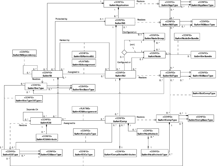
This information model contains this configuration information in the form of configuration objects of the classes defined by the specification. As a result, the information model is the most important tool in the hands of site integrators and site designers, who decide how the system needs to be put together, from what components it should be composed of and according to what policies they need to be managed in order to provide the appropriate CSIs.
The AMF information model also contains information about the current status of the system, such as which components have been instantiated and what their assignments are at any moment in time. Therefore it is also an essential interface for site or system administrators who need to be able to obtain any relevant information about the status of different entities in the system and also to perform administrative operations whenever it is necessary.
Considering the potential size of systems managed by the AMF one quickly realizes that the organization of all this information is vital for easy comprehension, overview, and administration. As we will see these were the guiding principles when defining the AMF information model.
6.3.3.1 Component Type and Component Service Type
In fact components participating in the same protection group typically run the same software, which means that most of their configuration information (such as the CLC-CLI commands to instantiate and to cleanup, the different associated timers, the component categories, and so on) is the same for them.
In the recognition of this and to simplify the configuration of these components the concept of component type was introduced to the AMF information model. Since not only components of a protection group, but any component running the same software may have these same features, the concept is not limited to protection groups. Instead, a component type can be defined for any set of components running the same software and requiring the same configuration information. This way the component type provides a single point of control for this common part of the configuration information.
Since the software associated with a component type typically has many versions, one may collect all these versions under a single umbrella, therefore the concept of a component base type became part of the AMF information model. Note that the AMF specification does not define what a version is, whether it reflects a different version of the software or a different configuration of the same software. It is left to the site designers to decide what the most appropriate use for these concepts for a given site.
For AMF to know how many and what components need to be instantiated, at least the component names need to be provided on an individual basis. Therefore for each of them there is a component object in the AMF information model describing at least the name of the component and the component type it instantiates. Other configuration attributes are associated with the attributes of the component type. If such an attribute is left empty that means that AMF applies by default the value given in the associated attribute of the component type object. Hence if the value is changed in the component type object, it applies to all components referencing this type and having their associated attribute empty. Otherwise when such an attribute is set for a particular component, AMF uses this value. Thus, setting such an attribute exempts the component from the control through the type with respect to this particular attribute.
These individual component representations are also convenient places to reflect the runtime status information of the component running in the system.
By similar analogy, the concept of component service base type and component service type were introduced for CSIs.
The component service type defines the set of the attributes—in terms of their names—that needs to be configured for each of the CSIs that instantiate this component service type. Each of these CSIs are configured by an object in the AMF information model which indicates: the name of the CSI which AMF uses to make the assignments, the component service type, and the attribute values for each of the CSI attribute names defined in this component service type.
6.3.3.2 Runtime Status of Components
To represent the status of components in the system a set of states were introduced to the information model as runtime attributes. The AMF API does not expose any of these states.
Component Presence State
To represent whether a component has been instantiated and is running in the system the presence state was introduced.
At system start no component runs in the system, all of them are in the uninstantiated presence state.
When AMF issues the instantiate CLC-CLI command (or the appropriate API callback for mediated components) the actions necessary to instantiate the component take place, and depending on the type of the application, it may take some time before the component becomes ready to take assignments. During this time the component is in the instantiating presence state.
If the component successfully registers with the AMF, the instantiation is successful and the component's state changes to instantiated. It means that the component has completed all necessary initialization procedures and it is ready to take CSI assignments.
Non-pre-instantiable components do not register, for them the successful completion of the instantiate CLC-CLI command indicates the completion of the instantiation.
When AMF decides that it does not need a component any more, it terminates the component to potentially free up the resources used by the component. It initiates such a termination via the API or the terminate CLC-CLI command. Alternatively, AMF may abruptly terminate faulty components using the discussed earlier cleanup CLC-CLI or its API equivalent. Regardless which way the termination is executed, the component's presence state becomes terminating until AMF can conclude that the termination or cleanup procedure was successful and therefore the component again is in the uninstantiated state.
The component is only fully functional in the instantiated state and it is not aware of any of these state values. The presence state is used by the AMF in evaluating the system state and within that the status of the different entities and also it is an important piece of information for system administrators.
The remaining three presence state values are all related to errors.
We have mentioned in Section 6.3.2.3 that AMF may decide to keep the CSI assignment with the component while it is being restarted in order to reassign it to the successfully restarted component. If this is the case then rather than driving the state machine through the terminating-uninstantiated-instantiating state transition sequence the actions are summarized in a single state value—restarting. This single value representation does not reflect the sequence of actions carried out by AMF to restart the component. AMF still terminates or cleans up the component—as appropriate—and then instantiates it.
The failure to instantiate a component is reflected by setting the component's presence state to instantiation-failed and the failure to terminate results in the termination-failed states.
The AMF may make a number of attempts to instantiate a component. The instantiation-failed state is set, when AMF exhausted all its attempts to repair the component by restart and therefore has given up on the repair.
AMF has only few tools to accomplish the termination and the termination-failed state is more critical. If the graceful termination does not succeed or it is not appropriate, the only option left is the cleanup CLC-CLI command. If this fails AMF has no other tools to handle the case at the component level.
The reason the termination-failed state is critical is that if the component was servicing any CSI when the termination attempt was initiated and this attempt has failed there is no guarantee that the component has stopped the service provisioning. This means that such a CSI becomes ‘locked-in’ with this failed component until the termination and therefore the withdrawal of the CSI can be guaranteed.
Component Operational State
The actual fact whether the AMF is aware of any error condition with respect to a component is reflected by yet another state, the operational state. The operational state may have the values enabled or disabled.
The enabled operational state means that AMF is not aware of any error condition related to the component. That is, none of the error detection mechanisms discussed in Section 6.3.2.6 has been triggered or if any of them was triggered, the restart recovery action is still in progress. In any other case, that is, if the recovery action is different from the component restart action then triggering the error detection mechanisms also results in disabling the component's operational state.
The operational state also becomes disabled if the component reaches the instantiation-failed or the termination-failed states.
Component Readiness State
If a component is healthy and therefore its operational state is enabled; it has been successfully instantiated, that is, the component has reported to the AMF that it is ready for assignments; all this does not mean that AMF can select this component for an assignment. It needs to take into consideration the environment of the component.
When both the component and its environment are ready for an assignment, the component is in the in-service readiness state. When either the component or its environment cannot take assignments, the component is in the out-of-service readiness state. And finally its readiness state is stopping if the component's environment—and therefore the component itself—is being shut down.
As we see the readiness state is a composite state. Its exact composition depends on the component category; however, for all components it includes the component's operational state and its environment's readiness state, which we will discuss later in section ‘SU Readiness State’. In addition, for pre-instantiable components the readiness state also includes the presence state since these components register with AMF (directly or indirectly through a proxy component) to report their readiness to take assignments.
In other words, a non-pre-instantiable component is ready for service as long as it is healthy and enabled; otherwise its readiness state is out-of-service. A pre-instantiable component needs to be enabled and instantiated as well, otherwise it is out-of-service. To be in-service, however, components of both categories need to be in an environment, which is in-service. Both component categories change to stopping or out-of-service as soon as the environment's readiness state changes to stopping or out-of-service respectively.
Note that some AMF implementations may allow components to report their HA readiness state with respect to particular CSI assignments. By setting its HA readiness state to a particular value for a CSI indicates what HA state assignments the component is capable of handling for that particular CSI in its current state. It may refuse HA state assignments not aligned with this request without AMF evaluating it as faulty. It also does not impact the component's overall readiness state.
Next we investigate what we mean by the environment of a component.
6.3.3.3 Compound AMF Entities and Their Types
A component typically participates in two types of collaborations: We have already mentioned the first one, the collaboration of components to protect a CSI forming a protection group. The second type of collaboration combines the service functionality each component provides to a functionality more desirable for their end-user. In this relationship components form the so called service units (SUs) and the combination of their CSIs create the SIs which we will explore next.
The Service Unit
The component boundary defines a fault zone, which does not necessarily coincide with the boundary of the desired functionality. It merely says what can be isolated and repaired on its own. It is a little bit like with cars, one does not want to replace the car's engine because a part, the spark plug, for example, failed in it. So the engine is composed from pieces repairable and replaceable on their own, but the functionality we are after is the engine's functionality of powering the car. Similarly we put together components so from their combined partial functionality we can make up the desired service functionality boundary.
Such a group of components is called a service unit. It is a logical entity known to the AMF—components are not aware of it—and visible only in the AMF information model. There is no application code associated only with the SU, which is not part of any of its component's code. It is a set of components. The intention is to be able to develop components independently and combine their functionality later as needed and by that realizing the commercial-off-the-shelf (COTS) paradigm.
Since the SU is defined at the functionality boundary it is expected that within this boundary fault propagation can still occur relatively often due to the tight collaboration of its components. Therefore the SU forms the next fault zone within the AMF information model. The collaboration may be so tight that the AMF even provides a configuration option to escalate a component failure right away to the failure of its SU.
This implied tight collaboration is further reflected by the requirement that all components of a SU need to be collocated on the same node and in the same execution environment. Any type of collaboration requires communication, and it is usually easier and more efficient to communicate within an execution environment than between them. This however also means that faults can also propagate easier within the execution environment than between them.
This collocation requirement means that, for example, local and external components cannot compose a single SU. It also means that contained components that form a SU must be contained in the same container component and all components of such a SU must be contained components. Even the container component needs to be part of a different SU as it executes in a different environment.
To further isolate fault zones, SUs do not share components. Each component belongs to one and only one SU.
The Service Instance
The combination of the CSIs provided by the components of a SU, that is, the workload at the boundary of the service functionality is called the service instance.
The question is what is really the semantics behind this term ‘service functionality boundary’?
It is not something easy to grasp or describe as the AMF—as we discussed earlier—is not aware of the user perceived service at all. As a result this functionality boundary can only be characterized by describing how AMF handles SIs.
As in case of SUs, there is nothing tangible associated with the SI beyond the CSIs it comprises from. When each of the CSIs in the SI is assigned to a component (as described in Section 6.3.2.3) in a SU it is said that the SI is assigned to that SU. AMF assigns all the CSIs of an SI to the components of the same SU in the same HA state. It selects the component for each CSI based on the component's capability model for the type of the CSI (i.e., component service type).
If a component is able to take more than one CSI assignment, AMF may assign more than one to it, but if there are more than one components available and capable of providing that CSI, AMF may distribute the assignments among them. That is, for CSIs being in the same SI does not guarantee their co-assignment to the same component. It only guarantees the assignment to the same SU, which may mean different components.
An SU may be able to provide more than one SI and AMF may use this additional capacity as needed. This also means that some components may remain unassigned in the SU when there is no need for their services, others may have assignments for CSIs of different SI.
Just like SUs are exclusive sets of components, SIs also cannot share CSIs even though this might be a very tempting idea when the functionality has a common portion. Instead, one should define CSIs of the same type in the different SIs, which may be assigned then to the same component when both SIs are served by the same SU.
The AMF moves around the assignments of SIs more or less independently therefore each SI needs to have the CSI definition independently to activate each of the required service functionality of the components.
To make these concepts more tangible let's assume this web-interface through which some database can be accessed. Typically the database software and the web-server software are developed by different software vendors and therefore we can assume that each of them integrated their solution with the AMF independently.
Now we would like to integrate them so they collaborate to provide our desired web-interface.
To achieve this collaboration we configure together into this single SU:
- the web-server software with the page content for the interface as one component; and
- the database component with the data content as a second component.
We already know that none of the SA-aware components is allowed to provide any service unless they have an assignment with the active HA state for a CSI. This means that to activate them we need to specify for each of these components these CSIs, which in turn will compose the SI representing this web-interface service. Let's say the web-server requires the IP address at which it should listen to the enquiries and a file name the entry point for the interface page content; and the database requires the location of the data and the address it should listen to enquiries.
When we want to provide this web-interface the representing SI will be assigned by AMF to our SU, which effectively means that AMF will callback each of these components with their appropriate CSI attribute settings and in the HA active state. From that moment on, anyone requesting the page at the address indicated to the web-server component in the CSI assignment will receive the view of the interface through which a database enquiry can be performed. When an enquiry is submitted through this page, the web-server component will generate an enquiry toward the database component at the address provided to the database component in its CSI and the component returns the enquiry result from the data it finds at the location it received as the second attribute.
Obviously the page and the data content do not come from the vendor and we need to provide them. The address of the database enquiry interface toward which the web-server generates the request is part of the interface page.
All is well as long as both components are healthy, but what happens if our database component fails?
The Service Group
At the component level components form protection groups based on the CSIs they protect. These components belong to different SUs. This is because the SU itself is a fault zone and may fail. So if the protection group was within the same SU AMF would not be able to fail-over the CSI.
When AMF fails over a CSI of a SI to another component in another SU, it also needs to fail- or switch-over all the other CSIs of this SI, so that all the CSIs are assigned to the same SU.
SUs that work together to protect SIs form a service group (or SG). To provide any protection we usually need at least two SUs in a SG. It was the traditional approach to redundancy that we would have one active and one standby element in the system and only the active element provides the functionality required. This simple strategy is still widely used, but from an economical and efficiency perspective it obviously doubles the cost of everything as it works only at 50% utilization.
It turns out that we can define other redundancy schemas that are more efficient and depending in the reliability of the different components may still satisfy our required level of SA. The AMF specification defines five different redundancy models according to which SGs may operate and protect their SIs. These models are:
- the 2N redundancy model;
- the N+M redundancy model;
- the N-way redundancy model;
- the N-way-active redundancy model; and
- the no-redundancy redundancy model.
We will take a closer look at each of these models in Section 6.3.4, but before doing so first we describe the common features of SGs that apply to all redundancy models.
A SG may protect more than one SI and these SIs are assigned to the SG at configuration time. It is a long-term association, which cannot be changed without impacting the availability of the service.
Also at configuration time the redundancy model and all the appropriate values for the model attributes are given, and at runtime the AMF implementation decides based on these parameters:
How many and which SUs of the SG need to be instantiated. It is possible that not all SUs configured for the SG are instantiated right away. Instead only a sufficient number of them are started initially and AMF instantiates others only when this becomes necessary, when the number of available instantiated ones drops below the level required by the configuration attributes. This built into AMF feature often referred in other systems as dynamic reconfiguration. In case of AMF the configuration implies a certain level of dynamism and its extent depends on some configuration attributes as we will see.
After some waiting time or when the required number of SUs becomes available, AMF decides about the most appropriate distribution of assignments for the different SIs protected by the SG. This includes both active and standby assignments for each SI as required by the configuration of the SG and the SI.
AMF makes the assignments for each of the SIs a SG protects to the selected SUs. Doing so components of one SU get the assignments for one HA state (e.g., active) assignment while for the other HA state (e.g., standby) assignment the assignments are given to components of another SU.
Whenever an event occurs that requires a change in the assignments (e.g., an SU needs to be failed over), AMF re-evaluates the situation and first of all isolates the error and tries to recover the SIs for which the assignment is lost by reassigning them to other SUs. During this the main concern is to recover the active assignments for them by turning if applicable the standby assignments into active and then if it is possible also provide the standby assignments as required. This may require the instantiation of SUs that were not instantiated so far. AMF will typically also engage in the repair of the components that failed as we have seen in Section 6.3.2.4.
When AMF evaluates the situation it applies the policies implied by the redundancy model and if applicable the recovery recommendation received with the error report or the default recovery configured for the component on which the error has been detected.
If AMF reacts to a failure, the most important decision is the identification of the fault zone at which the recovery and the repair needs to be executed. The smallest recovery zone is the component on which the error is detected. However as we noted sometimes this level is inadequate and a different recovery recommendation may be configured for the component itself or the SU is configured as the first fault zone. Other times the detected error may indicate for the entity monitoring the component that more than the component was impacted and it may suggest to AMF a different recovery action in its error report. Finally AMF also correlates errors occurred within the same SU and within the same SG over time. If several of them happen within a configured period of time, it deems the failures related to each other and escalates the recovery to the next fault zone.
Any SU within the SG must be able to take the assignment for any SI associated with the SG. However, the number of SIs that may be assigned to a SU simultaneously may be limited. For example, if a SG is composed of three SUs {SU1, SU2, SU3} and it is assigned to protect the service instances {SIA, SIB}, then AMF should be able to assign any of these SIs to any of the SUs. However, each of the SUs may be able to take only one such assignment either SIA or SIB, but not both at the same time.
The remaining AMF entities have one primary role: they define even higher level fault zones encapsulating incrementally more entities.
The AMF Node
According to the specification an AMF node is the collection of all AMF entities on a cluster (Cluster Membership service (CLM)) node.
While this definition seems to be straightforward it is not as the AMF node does not require the presence of a CLM node. It may be configured independently. In addition the actual list of entities in this collection may not be known until runtime. So here we would propose a slightly different definition:
An AMF node is a logical container entity for AMF components and their SUs which is mapped to a CLM node for deployment. This mapping is 1 : 1.
Since a CLM node is mapped to an execution environment (see Figure 6.3) such as an operating system instance, all the AMF entities collected by an AMF node execute in this same execution environment and AMF uses the command line interface of this OS instance to control the life-cycle of the components associated with the AMF node.
Figure 6.3 Mapping of the AMF node to the CLM node and to PLM execution environment (EE) [62].
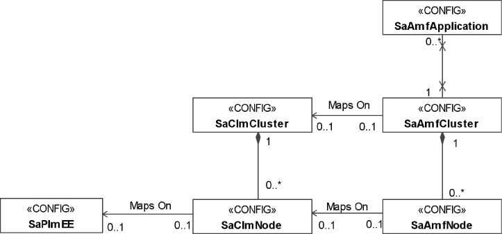
As discussed earlier components that execute in the same execution environment, for example, that run on the same instance of an operating system cannot be completely isolated from one another as they need to use common resources, the same memory, the same set of communication interfaces, and so on. Therefore the AMF node is the next higher fault zone (after the component and the SU).
To demonstrate it let's reconsider our example with the process, which leaks memory. Let's assume it is part of a component. The memory-leak may impact the execution of all processes running in this OS instance. Moreover, the shortage of memory may cause the failure of a different process in a different component before the leaky one; hence the restart of this failed component will be no remedy for the situation.
Not knowing the root cause of the problem or the justified memory use of each component it is impossible for the AMF to identify which component is the real offender, hence it will need to deploy the recovery escalation policies and widen the fault zones until it eventually captures the offending component. This is guaranteed in our case only at the AMF node level as this is the level where the common resources are shared. In particular, the same way AMF correlates failure for the SU and for the SG, it also correlates failures within the same node. When the number of recoveries within the same AMF node reaches a threshold the entire node is recovered.
While typically the AMF handles only AMF entities, when the recovery and the repair reaches the AMF node level AMF may attempt to repair the execution environment by restarting via the Platform Management service (PLM) [36]. This operation is referred as node fail-fast and depending on the configuration may range from operating system reboot to physical reset of a hardware element impacting therefore also the mapped CLM and PLM entities.
Indeed whenever a component (and therefore its SU) reaches the instantiation-failed or termination-failed states as discussed in section ‘Component Presence State’ the only repair AMF can attempt (if configuration permits it) is the node fail-fast, which abruptly terminates all components running on the node.
By contrast, a CLM node may get disconnected or a PLM entity such as a physical node may fail independently from what happens to the AMF controlled entities. Such a failure impacts all the AMF entities on the AMF node mapped to these PLM and CLM entities and the AMF needs to be able to handle such a situation and maintain SA.
Therefore AMF when making the different HA state assignments for the same SI, it gives preference to SUs that are located on different AMF nodes (and if possible even on different physical nodes). In this respect AMF's responsibility may be limited by the configuration it is given to manage.
Namely, SUs may or may not be allocated to particular nodes in the configuration. If an SU is assigned to a particular AMF node by the configuration, AMF must instantiate this SU on that node only and if all SUs happen to be allocated to the same physical node, AMF has no way to distribute the assignments so that it would protect against the failure of this physical node.
If there is no such configured allocation, AMF chooses the AMF node from the list of eligible nodes—called node group—at the moment it instantiates the SU for the first time. As long as there is a node available in the node group without any SU belonging to the given SG, AMF will not select a node which already hosts such a SU. The node group is also configured and it is a list of nodes that are equivalent for the purpose of hosting some SUs.
With all these considerations the AMF node is still a fault zone, which in most cases can be isolated without any service impact. This prospect changes with the last two fault zones that we will look at.
Before doing so as a side note, it is interesting to compare the AMF node with the container component since both of them are associated with a single execution environment yet these execution environments are represented by different AMF entities. The key distinguisher is the AMF's ability to access the execution environment. As we have seen in case of container components AMF can use the AMF API to communicate with the container component itself, but it has no direct access to the environment this container provides for the other components therefore it cannot execute the life-cycle control operations directly. In case of the AMF node, AMF has direct access to the execution environment; in fact the SA Forum middleware including the AMF implementation may run within this same environment.
The Application
For the AMF an application is a logical entity composed of SGs and SIs the SGs provide and protect.
The AMF application logical entity reflects mostly the boundaries of a software implementation delivered by a particular software vendor, that is, the generic interpretation of the word ‘application.’
As a result applications are considered relatively or completely independent from each other, which makes them good fault zones that can be isolated without serious impact of the rest of the system. However, since the application includes both the SIs and the SGs providing and protecting them, isolating this fault zone impacts at least all those SIs included in the application entity.
The questions are how the application fault zone is used and when it is appropriate to use.
As in other cases the isolation mean termination and restart of the entity; however, since the only tangible entities in our system are the components, the restart of an application is executed as the abrupt termination and restart of all the components composing the application. That is, all the components which are part of any SU whose SG belongs to the application. While executing this restart no service recovery is performed for the associated SIs. In fact, the goal is to terminate and restart the service functionality by terminating and restarting the SIs themselves so to speak. This obviously creates an outage for these SIs and the functionality they represent. If there are other applications depending on the functionality of the faulty one, they may suffer outage too. We discuss dependencies in detail in Section 6.3.3.5.
Such a drastic measure is appropriate only when the fault has manifested not only as an internal error (such as a failure of a redundant entity like a component or a SU), but it is visible already externally as a failure of the provided service functionality, which in turn is associated with the SIs of the AMF application. This also means that the error is likely to be part of the state information of the service functionality—the information exchanged between the active and standby entities for synchronization. Therefore its preservation—which is normally the goal—should be prevented in this case.
To guarantee that no state information is preserved by the redundant entities of the AMF managed application, the restart is carried out by first terminating all the redundant entities (SUs and their components) completely before starting to instantiate any of them again.
The AMF Cluster
The AMF cluster is the complete collection of AMF nodes and indirectly it encompasses all the entities managed by the AMF.
As each of the AMF nodes is mapped onto a CLM node the AMF cluster is mapped to the CLM cluster, which encompasses these CLM nodes hosting AMF nodes. However, it is not required that each CLM node of the CLM cluster hosts an AMF node, that is, the AMF cluster may be mapped only to a subset of the CLM nodes. The important point is that all the cluster nodes to which the nodes of an AMF cluster are mapped must belong to the same CLM cluster.
The reason for this is that the CLM is the authority to decide whether a CLM node is part of the membership. When a CLM node becomes part of the membership, it implies that it is healthy for running applications and it can communicate with the rest of the cluster.
When a CLM node joins the CLM cluster, the AMF node mapped to it becomes automatically available for AMF entities and AMF may start to instantiate them as necessary.
If a CLM node leaves the cluster membership the AMF is responsible for terminating all the components on the node.
From the AMF perspective the AMF cluster is the ultimate fault zone as it includes all the entities managed by an AMF implementation. The recovery action performed at this level is the cluster reset which goes beyond AMF entities. It is equivalent to the node fail-fast operation (discussed in section ‘The AMF Node’) applied to all nodes of the AMF cluster simultaneously. Typically this means the reboot of the operating system of the nodes, but the exact meaning depends on the PLM configuration for the execution environment of the node.
The same way as we have seen for the application, the intention is to preserve no state from the AMF cluster requiring the reset. This means that no node may start booting before all of them have been terminated.
The Types of Compound AMF Entities
For components and CSIs the component type, the component base type, the component service type, and the component service base type were introduced to collect the sets of entities that have common characteristics and to simplify their configuration. The same approach applies to the compound AMF entities with the exception of the AMF node and the AMF cluster. Thus, the AMF information model includes the concept of the service type, the SU type, the SG type, and application type and their base types. The base types have no additional semantics than collecting the set of entity types that can be considered as versions of the same software concept.
The versioned entity types have the following interpretation:
- The service type defines the common characteristics of a set of SIs and, in particular, the set of component service types instances of which can compose these SIs. It defines for each of these component service types the maximum number of instances that a SI may contain. That is, a SI of a particular service type may include zero or more—up to this specified maximum number of CSIs for a particular component service type.
This characterization of the service type facilitates the comparison of the capacity required from a SU to take an assignment for a SI of the type. Since no more than the maximum number of CSIs may be configured in an instance of the service type this defines how much capacity in terms of CSIs the components of the protecting SUs should provide.
- The counterpart of the service type for the entities of the provider side is the SU type. Its most important attribute is the list of service types the SUs of the type can provide and protect. To allow the capacity comparison it also defines the component types that should compose the SUs of the type and for each of the component types the minimum and the maximum number of components that can be included. The minimum number must be at least one so that there is at least one component in each SU that can provide each of the component service types of the SI the type of which is listed as supported service type.
- Two of the attributes defined in the SG type are important to mention.
The first one is the redundancy model. The SG type specifies the redundancy model for all of its instances. For each of the SGs belonging to the type only the configuration attributes of the particular redundancy model are given which tailor these SGs for the needs of the deployment site. Future will show whether the control of these attributes from the type is a simplification.
The second attribute is the list of valid SU types instances of which may compose the SGs of the type. Since any SU of a SG must be able to take the assignment for any of the SIs assigned to SG it is typical that all SUs of the SG are of the same type. In addition the same SU type means same component types, which boils down to the same set of software implementations, which obviously means less software cost.
However there are situations when a SG may be composed of SUs of different SU types. The most obvious one is during upgrade. Since the units of redundancy are the SUs the way to upgrade the SG without service impact is one SU at a time. Thus after the upgrade of the first SU it will typically belong to a new SU type and the SG will be heterogeneous from the moment the upgrade starts till the moment it completes.
Another reason may be that the AMF cluster is heterogeneous, for example, composed of nodes running two different operating systems. There might be some functionality that needs to be available across the OS boundary. The most obvious example of this is a middleware service. Since the components for the two different operating systems will be different implementations of this same service, they will belong to different component types and therefore different SU types. This is because for the SU type no alternative component types can be indicated. All component types listed in the SU type must be instantiated at least by one component in each SU of the type. Note however that even in case of a heterogeneous SG, all the SUs must be able to take any of the SIs, that is, components of either side should be able to take the CSI assignments for any of the SIs. However the distribution of the CSIs can be quite different, that is, the relation of components does not need to be 1 : 1.
- Besides its version the application type defines a single attribute for its application instances, which is the SG types the applications may be composed of. This list is not qualified further, that is, a given application instance may include SGs of all of the listed types or maybe a subset. However they may not include an SG whose type is not listed in the application type.
As we have seen the application AMF entity includes the SGs and also the SIs, so one may wonder why there is no service type list provided for the application type. The reason for this is that the SU types list service types their instances are capable of providing. As a result the list of valid service types is deducted from the inclusion of SG and SU types.
As we mentioned there are no types provided for AMF nodes and the AMF cluster. In case of the AMF nodes the node group plays a somewhat similar role to a type as it characterizes the equivalency of nodes from the perspective of hosting some SUs. It is not abstracted as a type because a node may belong to more than one node group, while in case of the types each entity belongs to one and only one of them.
Just like in case of the SG more experience may show that it is practical to introduce the type and base type for nodes as well. In case of the cluster since there is only one cluster in the system managed by a single AMF implementation there is no need for types. It may have a use when there are more than one AMF instances at a particular deployment site or the information model covers more than one site. These, however, are currently beyond the scope of the AMF specification.
The same way as in case of component types and component service types, the entities of these compound AMF entity types are configured individually by an appropriate configuration object. This configuration object at least provides two attributes: the entity's name and the entity type it belongs. Additional attributes may provide further configuration information some of which may override the configuration value provided in the type if they are provided.
These configuration objects also include runtime attributes that characterize the runtime status of the entity they represent. Next we are going to review the state information provided through the information model for the AMF compound entities.
6.3.3.4 Runtime Status of Compound AMF Entities
The AMF maintains the status information for the different compound AMF entities as a set of states. All these states are visible in the AMF information model as runtime attributes. They are not exposed through the AMF API.
This section does not cover the administrative state, which is discussed in Section 6.3.5 together with the administrative operation controlling it.
SU Presence State
The SU presence state reflects the life-cycle of the whole SU. Since the SU is a composition of components each of which has a presence state, the SU presence state is defined as the composition of these component presence states. It has the same values as the component presence state.
Since an SU may combine pre-instantiable and non-pre-instantiable components and their time of instantiation is different, the specification declares a SU pre-instantiable if it contains at least one pre-instantiable component, which in turn drives the presence state of such an SU. A SU is non-pre-instantiable if it consists of non-pre-instantiable components only.
The compositions rules for the SU presence state are the following:
- Uninstantiated:
When all components of the SU are in the uninstantiated state the SU is in the uninstantiated presence state.
- Instantiating:
When the first component moves to the instantiating state the SU's presence state becomes instantiating.
- Instantiated:
The SU becomes instantiated when all its pre-instantiable components have reached the instantiated state.
A non-pre-instantiable SU becomes instantiated when all its components reach the instantiated state.
- Restarting:
The SU presence state becomes restarting when the presence state of all of its already instantiated components becomes restarting. Non-pre-instantiable component that were not instantiated at the time of the restart remain uninstantiated and do not impact the restarting state.
- Terminating:
When the first pre-instantiable component of an already instantiated SU moves to the terminating state, the entire SU moves to the terminating state.
A non-pre-instantiable SU moves to terminating state with its first component moving to the terminating state.
- Instantiation-failed:
If any component of the SU moves to the instantiation-failed state, the SU also moves to the same state. If there is any component within the SU that already reached the instantiated state AMF terminates it.
- Termination-failed:
If any component of the SU moves to the termination-failed state, the SU's presence state also becomes termination-failed. AMF terminates all the other components in the SU as well.
Table 6.2 summarizes the possible component presences states for each of the SU presence states with respect to the pre-instantiability of the components.
Table 6.2 Possible combinations of component and service unit presence states
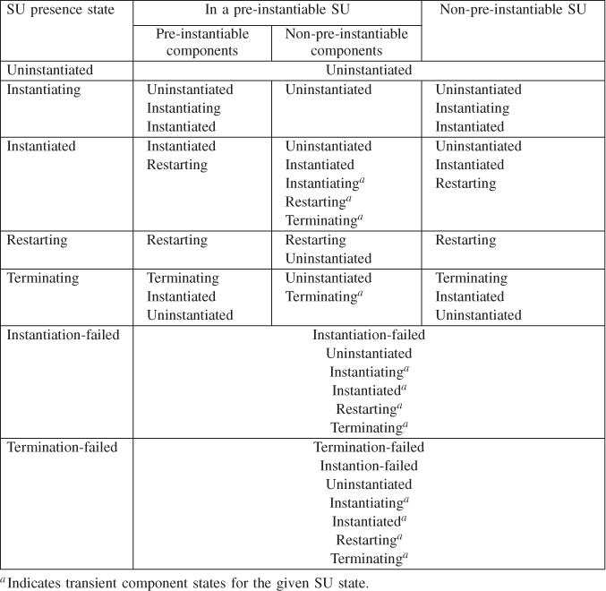
SU Operational State
Just like the presence state, the operational state of a SU is the composition of the operational states of the components composing the SU.
The SU is enabled when all its components are in the enabled operational state.
As we have seen at the component operational state this does not mean that the AMF is not aware of any error condition. It may be, however it is still engaged in the restart recovery action the outcome of which shall determine the operational state.
If any of the components within the SU transitions to the disabled state, the SU operational state also becomes disabled.
In particular, the SU becomes disabled if any other than the component restart recovery action was triggered or if any of its components transitions to the instantiation-failed or termination-failed states. In addition to the operational state change, these later cases also cause the SU presence state to transition to the instantiation-failed or to termination-failed states respectively.
When a SU becomes disabled the AMF engages in an automatic repair action. As we have seen for components the repair is executed as a restart of the component and since the SU is the composition of its components, the SU repair implies the restart of all of its components. If the restart of all the components is successful, the repair is successful and AMF re-enables the SU's operational state.
The automatic repair of an SU may not be appropriate in all cases therefore the configuration allows its disabling for a particular SU or within the SG.
The repair action is disabled for a particular SU usually due to or for the time of some maintenance operations. For example, the software of the components has been upgraded after which a failure is likely due to this upgrade; therefore the restart of the components cannot resolve it and would be a futile. The failure needs to be brought to the attention of the entity performing the upgrade—typically the Software Management Framework (SMF) [49].
Disabling the automatic repair operation in the scope of the SG, on the other hand, is typically related to the service functionality itself, for example, if the restart of a SU may cause some state inconsistency at the service functionality level, or if it requires actions that cannot be controlled by the AMF.
AMF does not repair an SU when the automatic repair action is disabled for the SU or if it is in the instantiation-failed or to termination-failed states and escalation is not possible. In these cases an external intervention is required to recover the SU to the healthy state. Section ‘Repaired’ discusses these repairs.
SU Readiness State
The SU's readiness state determines whether the AMF may select the SU for an assignment. The state values are similar to the component readiness state values, that is, in-service, out-of-service, and stopping.
There are three contributing factors to the decision whether an SU is in-service:
- the SU's environment, whether it is ready so that the SU may take an assignment;
- the SU itself if it is ready to take assignments; and
- whether the SU is allowed to take assignments.
The first condition depends on the AMF node containing the SU. It must be mapped to a CLM member node, which essentially means that there is a running operating system instance which is healthy and capable of executing programs and therefore the software associated with the components of the SU. The AMF node must be enabled, which we will discuss in section ‘AMF Node Operational State’.
If the CLM node is not a member or the AMF node is disabled the SU readiness state is out-of-service.
The second condition depends on the SU operational state and for a pre-instantiable SU on its presence state:
- a non-pre-instantiable SU is always ready to take assignments as long as its operational state is enabled;
- a pre-instantiable SU is only ready if it is enabled and it is in the instantiated or restarting presence states.
The instantiated state implies that all the pre-instantiable components of the SU have been successfully instantiated, which in turn means that all of them have registered directly or indirectly with AMF and therefore indicated their availability.
A SU is in the restarting state if all of its already instantiated components are being restarted and in the restarting state.
An administrator may decide to stop or to take out-of-service some AMF entities. This is controlled by the administrative state of the appropriate entities which will be discussed at length in Section 6.3.5.2.
In any case, if the administrator initiated a shutdown or made ineligible for service the SU itself or any of the compound entities that includes the SU (e.g., its parent SG or hosting AMF node, etc.) then the SU readiness state becomes stopping in case of a shutdown and out-of-service otherwise.
The SU's readiness state reflects back to its components as the readiness of their environment, which is one of the factors taken into consideration when determining the readiness state of a component.
One may perceive the SU readiness state as the synchronization element between the states of its components. The components may become in-service only if their SU reaches the in-service readiness state. Only at this moment AMF may assign CSIs to the SU's components.
When the SU goes out-of-service, all of its components go out-of-service simultaneously and AMF withdraws their assignments.
When the SU moves to the stopping state, all its components move to the same readiness state and AMF assigns the quiescing HA state for their current active assignments. Section ‘Shutdown’ provides more details under what conditions this may occur.
SU HA State
The same way as the component HA state reflects the role the component is taking in servicing a CSI (see Section 6.3.2.3), the SU HA state indicates the role the SU takes on behalf of an entire SI. Again, the values are the same as seen for the component HA state: active, standby, quiesced, and quiescing.
In fact, the HA state assignment at the SU level is accomplished by a set of HA state assignments at the component level. For each CSI of the SI the AMF selects a component of the target SU and assigns the CSI in the desired HA state.
It depends on the redundancy model how AMF distributes the roles on behalf of a given SI among the SUs of the SG. It will try to satisfy first the required active assignments for all the SIs. If this has been satisfied then it proceeds to make the required standby assignments. When AMF selects the components within each of the SUs, it considers their capability model for the type of the CSI it wants to assign to them and their current assignments.
Pre-instantiable components may implement any of the following capability models for each of the component service type they can provide:
- 1_active: The component can accept only one CSI assignment at a time and only in the active HA state, it cannot take standby assignments.
- x_active: The component can accept ‘x’ CSI assignments at a time and all of them only in the active HA state, it cannot take standby assignments.
- 1_active_or_1_standby: The component can accept only one CSI assignment at a time either in the active or in the standby HA state.
- 1_active_or_y_standby: The component can accept either one CSI assignment in the active HA state or up to ‘y’ simultaneous assignments in the standby HA state. It cannot accept active and standby assignments at the same time.
- x_active_or_y_standby: The component can accept simultaneously either up to ‘x’ CSI assignment in the active HA state or up to ‘y’ assignments in the standby HA state. It cannot accept active and standby assignments simultaneously.
- x_active_and_y_standby: The component can accept up to ‘x’ CSI assignment in the active HA state and up to ‘y’ assignments in the standby HA state, all at the same time.
‘x’ and ‘y’ are configuration attributes for the different models. The total number of CSI assignments of a given component service type must not exceed the value indicated by the capability model in the selected role. The component may implement a different capability model for each different component service type it supports.
Non-pre-instantiable components implement the non-pre-instantiable capability model, which means that the component needs to be instantiated when it becomes associated with a single CSI in the active HA state.
When assigning the active HA state of an SI to a SU, AMF calls back the selected components of the SU to assign the active HA state on behalf of the CSIs of the SI, one component for each CSI of the SI. All these callbacks must be successful for the SU successfully assuming the active HA state.
AMF assigns the standby HA state in a very similar manner, however if it cannot assign the standby HA state of some (or even all) CSIs of the SU because there are no components that can take the assignment due to their capability model, which does not allow standby assignments at all, the assignment is still successful.
To clarify this policy let's consider the following example: there are two service units {SU1, SU2} with two components in each {{SU1.C1, SU1.C2}, {SU2.C1, SU2.C2}}. They provide and protect an SI with two CSIs {CSI1, CSI2}. Components C1 have the 1_active_or_1_standby capability model for the component service type of CSI1. These components implement a database. Components C2 manipulate this database and since all the state information necessary for them is stored in the database they have the 1_active capability model for the component service type of CSI2.
When AMF assigns the active HA state to SU1 on behalf of our SI, it calls back SU1.C1 with the active assignment for CSI1 and SU1.C2 for CSI2.
When AMF assigns the standby HA state to SU2, it only calls back SU2.C1 with the standby assignment for CSI1. AMF does not attempt to assign CSI2 to SU1.C2 as it is not capable of accepting standby assignments.
Note that if there was a second SI to protect and AMF's only option was SU2 for this task, the assignment would not be successful as SU2.C1 can take only one standby assignment.
As explained at the component HA state, the quiesced HA state is used to indicate to the component that its assignment is being switched over and it needs to stop its service and hold the state for the standby to which the assignment is being switched over. The quiesced state has the same meaning for the SU but at the SI level.
Let's develop our example further considering a switch-over.
First AMF assigns the quiesced HA state to the currently active SU, that is, it calls back SU1.C1 with the quiesced assignment for CSI1 and SU1.C2 for CSI2. After the components responded, AMF can proceed with moving the active assignment to SU2 and calls back SU2.C1 with the active assignment for CSI1 and SU2.C2 for CSI2 even though this later one had no standby assignment. When completed, AMF may assign to SU1 the standby assignment for the SI by calling back SU1.C1 with the standby assignment for CSI1 and removing CSI2 from SU1.C2.
One may wonder what the difference is between the 1_active and the non-pre-instantiable capability models. Considering our example we could implement our C2 components as non-pre-instantiable components. This means that the component is not SA-aware and AMF must instantiate it when it needs to be assigned active. Our scenario changes as follows:
- When AMF initially instantiates SU1 and SU2, it instantiates only components C1. When it decides to assign the active HA state to SU1, it calls back SU1.C1 with the assignment for CSI1 and also instantiates SU1.C2. The successful instantiation is equivalent to assigning CSI2 to SU1.C2. To make the standby assignment AMF only assigns CSI1 to SU2.C1.
- To execute the switch-over AMF calls back SU1.C1 with the quiesced HA state for CSI1 and terminates SU1.C2 to prevent it providing service. Then AMF calls back SU2.C1 to change its standby assignment to active for CSI1 and it also instantiates SU2.C2. When completed, AMF changes the quiesced assignment of SU1.C1 to standby for CSI1.
Note how this scenario can be adapted to integrate existing HA applications with the AMF that do not implement the AMF API.
Finally we need to mention the quiescing HA state, which again have the same meaning at the SI level for the SU as it has at the CSI level for the component. This is straightforward as the state is assigned to the SU by assigning the SI's CSIs in the quiescing HA state to the components currently active for these CSIs. This instructs the components to stop serving new requests, but continue to serve already initiated requests until completion.
Table 6.3 summarizes the possible HA state transitions of a SU on behalf of one given SI and the triggering operations.
Table 6.3 Possible HA state transitions of a service unit
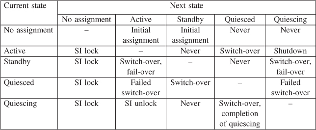
The SU may be assigned active or standby as an initial assignment. When we do not want to provide the SI any more we can lock it for immediate stopping of the service or shut it down for graceful termination. Section 6.3.5.1 provides more details on these actions.
AMF Node Operational State
The operational state of the AMF node indicates whether the AMF is aware of any error conditions at the node level. In other words, whenever a recovery action has been triggered by a component failure at the node level, in addition to disabling the operational state of the component, the operational state of the entire node hosting the component also becomes disabled. These recovery actions are the node switch-over, node fail-over, and the node fail-fast. They reflect that the fault causing the error is in the execution environment of the component therefore the recovery is escalated to this fault zone.
In the absence of any of these conditions and after a successful repair the operational state of an AMF node is enabled; otherwise it is disabled.
Node Switch-Over
To perform the node switch-over operation AMF abruptly terminates the failed component and fails over all the CSIs assigned to the component in the HA active state. The cleanup operation must be successful before AMF can assign the CSI to another component.
If the SU of the component is set to fail-over its components together, then AMF abruptly terminates the entire SU and fails over all SIs assigned in the HA active state to the SU.
In addition AMF switches over all the CSIs assigned in the HA active state to other components hosted on the node, that is, components that belong to other SUs and those that were not terminated abruptly.
Node Fail-Over
AMF fails over all the CSIs assigned in the HA active state to components hosted on the node. Regardless of their operational state the components are abruptly terminated and the cleanup operations must be successful before AMF can assign the CSIs in the HA active state to other components in the cluster.
Node Fail-Fast
Node fail-fast is similar to node fail-over, but rather than staying within the scope of AMF entities, the AMF performs a low level reboot (e.g., at the operating system or at the hardware level) of the disabled node using the PLM. At the same time it fails over all the CSIs assigned in the HA active state to components hosted on the node. At least the termination part of the fail-fast operation must be successful before AMF can assign the CSIs to other components.
When the fail-fast completes successfully, AMF re-enables the operational state of the AMF node as fail-fast operation is also a repair action.
After performing the node switch-over and node fail-over recovery actions the AMF node is still disabled so to repair it AMF may engage in an automatic repair action which means the termination of all remaining components hosted on the node and their re-instantiation as necessary.
This automatic repair action may be disabled for some AMF nodes in which case the repair needs to be performed by an administrator.
SI Assignment State
So far we looked at the states that reflect the status of the service provider entities, but from those it would be difficult to figure out what the status of the services our system is providing. This is the purpose of the SI assignment state which summarizes whether the SI is provided or not, and if it is provided whether AMF could make all the intended assignments for the SI or not.
A SI is unassigned if the AMF could not assign it to any of the SUs of the protecting SG in the active or the quiescing HA state. As we have seen earlier these are the only states in which the components (and therefore their SUs) provide the service functionality associated with the CSIs.
If AMF successfully assigned all the intended assignments of a SI (active/quiescing and standby) to the SUs of the SG, the assignment state of this SI is fully assigned.
When AMF succeeded with some of the assignments, but not all the intended ones and the assignments includes at least one active or quiescing assignment for the SI, the SI has the partially assigned assignment state.
For the purpose of the assignment state, the success of the assignments is evaluated at the SU level. As our example at the SU HA state demonstrated, it is possible that not all CSIs of the SI have a standby assignment when the SI is considered successfully assigned at the SU level. That is, a SI may be in the fully assigned state even though some of its CSI have no standby assignments.
6.3.3.5 Dependencies Among AMF Entities
Throughout the discussion we have seen that there is some implied dependency between certain component type categories. For example, a contained (or proxied) component cannot be instantiated without its container (or proxy) being already instantiated and assigned the container (or proxy) CSI. The AMF is aware of these dependencies and implies them as necessary. For example, if a container component needs to be terminated, AMF will switch-over the services as necessary for its contained components and terminate them first.
However in many cases software and service functionalities have dependencies among each other that AMF is not aware of implicitly and therefore needs to be configured.
As discussed in section ‘The Service Unit’ the SU represents the set of components in the tightest collaboration. This implies that the strictest dependency would occur in this scope. The AMF defines two types of dependencies in the scope of the SU. The first one is the instantiation level.
The instantiation level allows the specification of a particular order of instantiation for the components of a SU. The AMF instantiates the SU by instantiating its components in the incremental order of their instantiation levels. Components of a higher instantiation level are instantiated only after all components of the lower levels have been instantiated successfully. Similarly when tearing down a SU the components are terminated in the reverse order of their instantiation level.
Since a component becomes instantiated when it registers with AMF, the instantiation order should cover all the dependencies of the software that needs to be satisfied up to the moment of the registration.
Dependencies of components that need to be satisfied after instantiation and required to provide the functionality associated with a CSI needs to be captured as CSI dependency within the SI.
The CSI dependency defines the order in which AMF assigns the active HA state of different CSIs of a SI to the components of a SU. It requires that AMF assigns CSIs of the SI according to their dependency, that is, it assigns first the independent CSIs then their immediate dependents, and so on.
AMF withdraws the active assignments in opposite order of the CSI dependency. If any of the active CSI assignments within this chain of dependency is removed, for example, due to a failure, AMF withdraws immediately all the CSIs assignments depending on this CSI.
Note that the CSI dependency does not apply to the standby HA state assignments since as a result of the standby assignment these components collaborate only within the protection group, which means components of other SUs; they do not collaborate with other components of their own SU.
Finally components may collaborate and therefore may have dependency on each other at the SU boundary. Again, this dependency happens only when the components have the active assignments and is captured as dependency between SIs.
The SI dependency indicates the order in which AMF assigns the active assignment of the different SIs within the cluster. As in case of the CSI dependency, AMF withdraws the assignments in the order opposite to the dependency. But as opposed to CSI dependency this withdrawal is not immediate.
Since the SI dependency reflects a looser coupling, it may tolerate missing some dependency for some short period of time.
Since it is defined at the SI level, SI dependency does not imply the collocation of the components as instantiation level and CSI dependency do. It is possible even for dependent SIs of the same SG that they are provided by different SUs of the SG.
It is important to note that these entity dependencies do not have to reflect only software dependencies. Since they imply ordering, they may be defined purely for such purpose. For example, simultaneous instantiation at system start may put too much burden on the system, so instantiation order can be used for such purpose; however, it applies only within a particular SU. The instantiation of SUs cannot be staged with respect to each other.
A second note is that when one defines dependency between entities that have implicit dependencies, the explicit dependency cannot contradict the implicit dependencies. For example, one must not define that SI1 depends on SI2, if CSI1 in SI1 is provided by a container component and SI2 is by an SU of contained components requiring CSI1 as their container CSI.
Since in case of CSI and SI dependencies, each dependency is given as a partial order between the dependent and its immediate sponsors, one needs to be wary about cyclic dependencies.
It is often confusing and hard to grasp, but the AMF treats SGs of contained components exactly the same way as SGs formed from any other components including those encompassing the container components. The model does not reflect the containment relationship as an additional level in the hierarchy. In the model the relationship can only be tracked down through the container CSI through which the life-cycle of the contained component is mediated by one of the container components.
6.3.4 Redundancy Models
The AMF distributes the assignments for the SIs protected by a SG based on the redundancy model of the SG introduced in section ‘The Service Group’. The redundancy model determines the number of assignments each SI has and how they are distributed among the SUs of the SG. In this section we will take a closer look at each of the redundancy models defined in the AMF specification.
Throughout the section we use an example with the same basic setup: a SG with four SUs protecting two SIs. We show the initial distribution of assignments considering different redundancy models for the SG and the changes performed by AMF after it receives an error report for one of the components with an active assignment.
6.3.4.1 No-Redundancy Redundancy
The simplest redundancy model is the no-redundancy model, which sounds like an oxymoron, but it is not and here it is why: in this model for each SI at most one assignment can be made either in the active or in the quiescing HA state. So from this perspective this model implies no redundancy. However, since in the SG there are many SUs each of which is capable of providing any of the SIs protected by the SG, if one SU fails and it was serving a SI, then AMF can assign this SI to any other SU within the same SG provided there is one available for the assignment. So in this respect this model indeed provides redundancy. This redundancy model suits applications or parts of them that have no service state information to be maintained for service continuity and therefore no need for a standby.
The AMF puts some limitations on SGs with the no-redundancy redundancy model. Namely, in this model an SU may take at most one SI assignment. This requires that in the SG there is at least as many SUs as SIs it protects and at least one additional one to have some redundancy.
Let's assume a SG with four service units {SU1, SU2, SU3, SU4} protecting two service instances {SI1, SI2} according to the no-redundancy redundancy model. The configuration also indicates that three out of the four SUs need to be kept in-service.
First AMF instantiates service units {SU1, SU2, SU3} and assigns the SIs to the first two: SU1 provides SI1 and SU2 provides SI2 as shown in Figure 6.4.
Figure 6.4 No-redundancy redundancy model example: initial assignments.
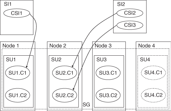
Let's assume that SU2 fails at one point. As a result the AMF performs the following actions:
- It cleans up SU2 and when succeeds AMF assigns SI2 to SU3 as part of the fail-over operation as shown in Figure 6.5. The successful cleanup guarantees that SI2 was indeed removed from SU2.
Figure 6.5 No-redundancy redundancy model example: assignments after recovery.
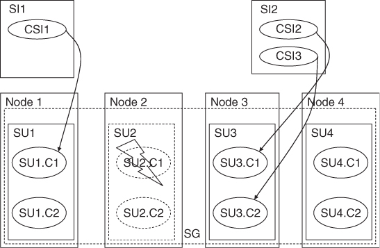
- At the same time to maintain the number of in-service SUs, AMF instantiates SU4. Since with that the number of in-service SUs is satisfied AMF does not instantiate SU2 for the time being.
2N Redundancy
2N is the best known redundancy model, although it is often referred as 1+1 or active-standby redundancy.
Indeed it implies that for each SI there can be at most two assignments: one in the active (or equivalent) and one in the standby HA states. Furthermore, the active (and equivalent) assignments for all SIs the SG protects are given to one SU in the SG, and all standby assignments are given to another SU. Often the SU with the active assignments is referred as the active SU and the one with the standby assignments is called the standby SU.
This means that the SGs should include at least two SUs, and each of these SUs should be able to accept the assignments for all the SIs the SG protects at the same time.
Of course, there could be more than two SUs in the SG, but at any given moment only (at most) two of them will have actual assignments, and only one will provide the actual service functionality. So the efficiency of this schema is 50% utilization at best.
Let's consider the same scenario as for the no-redundancy model, but assume that the SG protects the two SIs according to the 2N redundancy model. Let's also assume that each of the SUs have two components {C1, C2} and SI1 have one component service instance CSI1, while SI2 has two component service instances {CSI2, CSI3}.
Again, first AMF instantiates the first three service units {SU1, SU2, SU3}. It assigns both SI1 and SI2 in the active HA state to SU1 by assigning CSI1 and CSI2 to C1, and CSI3 to C2. Similarly it assigns both SIs to SU2 in the standby HA state as seen in Figure 6.6.
Figure 6.6 2N redundancy model example: initial assignments.
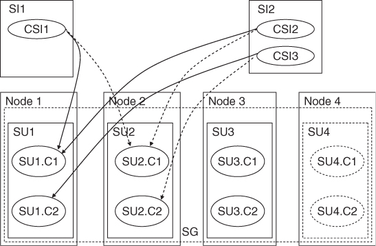
Let's assume that the AMF receives an error report that SU1.C2 is faulty and needs to be failed over. AMF proceeds as follows:
It cleans up SU1.C2 and when successful it fails over the active assignment for CSI3 to its standby SU2.C2. Meanwhile since SU1's readiness state changes to out-of-service with the termination of SU1.C2, AMF initiates a switch-over for SI1 too assuming SU fail-over is not configured. It puts the SU1.C1 into the quiesced state for both CSI1 and CSI2 and when confirmed AMF switches over these assignments to their standby SU2.C1.
Now, AMF can proceed to assign SU3 as the new standby for both SI1 and SI2. In addition to restore the number of in-service SUs it also instantiates SU4 while it terminates the remaining components of the failed SU1. Figure 6.7 shows the assignments after the performed recovery.
Figure 6.7 2N redundancy model: assignments after recovery.
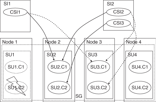
Note that even if SU1's readiness state did not change, SI1 would be switched over together with SI2 as all SIs must be assigned to the same SU in the active HA state for the 2N model. Moreover, if the SU was set to fail-over as a single unit, AMF would need to fail-over all the CSIs.
Some AMF implementations could also select to repair SU1 before instantiating SU4. This choice also could be influenced by some other configuration attributes.
6.3.4.2 N+M Redundancy
Better resource utilization can be achieved with the N+M redundancy model. This still implies one active (or equivalent) and one standby assignment for each SI. It also means that a SU may only have active or standby assignments, so the notion of active and standby SUs is still valid. However the number of SUs with assignments is not limited to 2, but as the name suggests there are N active and M standby SUs in the SG. There is no restriction on the relation of N and M, however most often N is greater than M to improve utilization. In particular M = 1 is the most widely used case.
The 2N model can be considered as a special case of the N+M model, where N = M = 1.
The AMF distributes the active assignments for all the SIs of the SG among the N active SUs and the standby assignments among the M standbys. The goal is to maintain all the assignments, that is, have all SIs fully assigned, but this may not always be possible so the next goal is to maintain at least the active and equivalent assignments for all the SIs, that is, have them partially assigned.
The specification does not indicate how the distribution needs to be done. Most importantly it does not currently require an even distribution of the active assignments among the active SUs and therefore AMF implementations may distribute them differently and unevenly.
The specification provides only one attribute to control the maximum number of active assignments an SU may take, which can be used to even out the number of assignments, but if it is used solely for this purpose and not due to capacity limitations, it may also force AMF to drop assignments when it would not be necessary.
Another issue not regulated by the specification relates to the distribution of the standby assignments: It is not required today that all the standby assignments for SIs assigned to an active SU should be given to the same standby SU. If not, when an active SU fails and AMF fails over its SIs to the SUs having the standby assignments, then suddenly more than one SU need to take over the assignments of the one that failed. From all these SUs all the other standby assignments need to be withdrawn as in this model a SU may only have active or standby assignments.
In general, there is a notion of a preferred distribution of SI assignments within a SG. It is determined through the correlation of different configuration attributes, such as the already mentioned number of active and standby SUs and their maximum number of assignments, but also different ranks that can be given to SUs within an SG and to SIs of the system. The procedure to get back to this ideal distribution is called auto-adjust and controlled also by a configuration attribute.
One should realize however that the assignments cannot be shuffled around at will, for example, to achieve better utilization. AMF uses a series of switch-over procedures to execute an auto-adjust and re-arrange the assignments. In the switch-over the least service impact is guaranteed by providing the time when the current active and the to-be-active components can synchronize the service state. During this synchronization however the service functionality is suspended. Hence AMF gives preference to switch-over to the standby. Thus, if there is a standby, AMF will move the active assignment to the current standby and vice versa. It may take quite a few steps until the intended preferred assignment distribution is reached through such switch-overs.
Let's consider again an example. We have the same SG of four SUs protecting the same two SIs, but according to the N+M redundancy model, N = 2 and M = 1.
Again, first AMF instantiates the first three service units {SU1, SU2, SU3}. It assigns the active HA state for SI1 to SU1 and for SI2 to SU2. In particular CSI1 is assigned to SU1.C1, CSI2 is assigned to SU2.C1 and CSI3 is to SU2.C2. AMF assigns both SIs to SU3 in the standby HA state. The initial assignments are shown in Figure 6.8.
Figure 6.8 N+M redundancy model example: initial assignments.
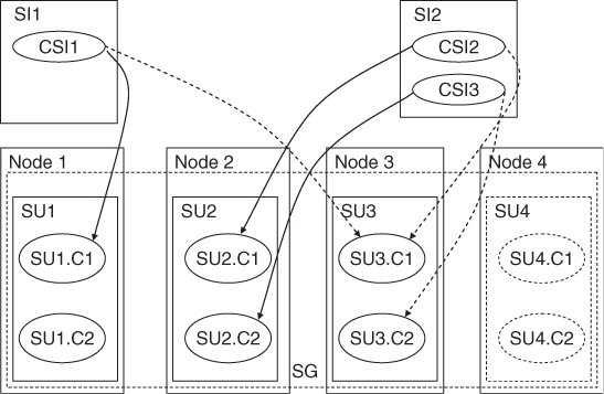
Let's assume that the AMF receives an error report that SU1.C1 is faulty and needs to be failed over. AMF proceeds as follows:
- It cleans up SU1.C1 and in parallel it instantiates SU4. When successful it moves the standby assignments for SI2 from SU3 to SU4, and it fails over the active assignment for CSI1 (i.e., SI1) to its standby SU3.C1. When completed AMF also assigns to SU4 the standby role for SI1 as seen in Figure 6.9.
Figure 6.9 N+M redundancy model example: assignments after recovery.
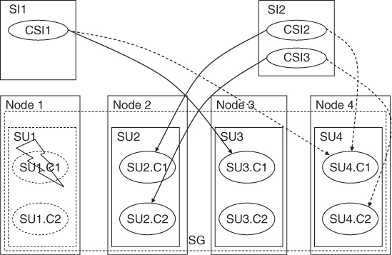
- AMF also completely terminates the failed SU1.
Note that the exact sequence of actions taken by an AMF implementation may be somewhat different from the above. The key point is though that it must guarantee that the assignments of the failed component are released completely (e.g., there is no process remaining in the system that may still serving any of the CSIs and which is now out of control) before they are assigned to another component. Hence the cleanup operation is part of the fail-over and typically needs to complete before AMF can fail-over the CSIs.
6.3.4.3 N-Way Redundancy
Considering the benefits and the limitations of the N+M redundancy model another schema appeared which is called in the AMF specification the N-way redundancy model. It removes many of the limitations of the other models: while it still implies one active (or equivalent) assignment for each SI, it allows more than one standby assignments for each of them, and this number may differ for each SI protected by the same SG.
It completely removes the notion of active and standby SUs; any SU in the SG may take active and standby assignments at the same time as long as they are not for the same SI.
The specification currently requires that the components used in a SG with the N-way redundancy model should provide their component service types according to the x_active_and_y_standby component capability model. This seems to imply that when AMF needs to make a standby assignment for a SI, it should be able to make it for all of its CSIs and also that it needs to use the same components in the SU that have active assignments. (One may question whether with these requirements the specification went overboard as (i) whether a standby assignment is required depends on the service functionality as we have seen and not on the redundancy model and (ii) since there is no need that the same component should be assigned active and standby simultaneously, one may achieve the same result at the SU level simply by using more components with a weaker capability model.)
The N-way redundancy model provides a configuration with better control over the distribution of the different assignments. Namely, each SI may have a different affinity to the different SUs of the SG. This is expressed through the ranking of each SU for each SI. AMF uses this information at runtime and gives the active assignment for a SI to its highest ranking SU among those available for the assignment. The next highest ranking SU will get the standby assignment, and so on.
Again the goal is to first make all SIs at least partially-assigned and then if it is possible then make them fully assigned. During this AMF must follow the SI-SU ranking as a recipe book whether it provides an even distribution of the assignments among the SUs or not. If the configuration provides equal ranking for some or all of the SUs it is implementation specific how AMF distributes the assignments.
To demonstrate the N-way redundancy model let's consider again an SG with four SUs {SU1, SU2, SU3, SU4} protecting two service instances {SI1, SI2}. The SUs again have two components each, and SI1 has one component service instance CSI1, while SI2 has two CSI2 and CSI3. The preferred number of in-service SUs is three as before.
For each of the SIs we would like to have two standby assignments. Each of the SIs have their own ranking of SUs: for SI1 this defines the order {SU1, SU2, SU3, SU4}. It is the same as the rank of SUs within the SG. For SI2 the ranking defines {SU2, SU3, SU4, SU1}.
At the start AMF instantiates {SU1, SU2, SU3} as they have the highest ranks within the SG. Then it assigns the active HA state on behalf of SI1 to SU1 and on behalf of SI2 to SU2 as these are the top ranked SUs for each of the SIs among those instantiated. AMF also gives the two standby assignments for SI1 to SU2 and SU3, and for SI2 to SU3 and SU1 as indicated by their ranking for the in-service SUs. The initial assignments are shown in Figure 6.10.
Figure 6.10 N-way redundancy model example: initial assignments.
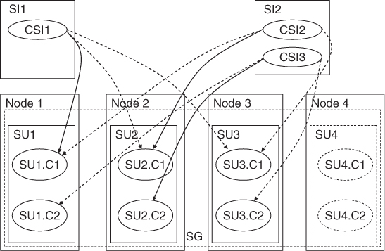
Let's assume that at one point AMF receives an error report for the C1 component of SU1 with the recommended recovery of component fail-over. It has currently the active assignment for CSI1 and the standby assignment for CSI2. AMF executes the following actions in reaction to the report:
It cleans up the faulty SU1.C1 component and once completed it fails over SI1 to the first standby, which is SU2. The termination changes SU1 readiness state to out-of-service, so AMF also removes from SU1 the standby HA state assignments for CSI3 and CSI2. AMF instantiates SU4, which becomes the second standby for both SI1 and SI2. AMF also terminates the remaining component of SU1. The new situation is shown in Figure 6.11.
Figure 6.11 N-way redundancy model example: assignments after recovery.
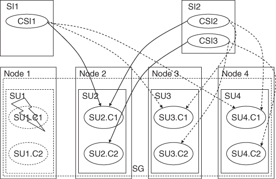
6.3.4.4 N-Way-Active Redundancy
The N-way-active redundancy model accomplishes in SA Forum systems what traditionally referred as active-active or load-sharing redundancy.
It is similar to the no-redundancy redundancy model as it only supports active HA state assignments for the SIs, but it allows more than one active assignment per SI. It also removes the limitation that at a time only one SI can be assigned to an SU.
This means that as far as the AMF is concerned all the SUs that receive an assignment for a given SI provide the same service functionality at the same time. They are sharing the workload represented by the SI. AMF cannot and does not distinguish these assignments; all the components involved receive the same CSI name and same CSI attribute values for a particular CSI of the SI in the same active HA state. As a consequence, AMF cannot give two assignments for the same SI to the same SU.
The multiple active assignments also imply that if a component fails and therefore stops servicing an assignment for a particular CSI, from AMF's perspective the service functionality is still provided by the components and SUs that have an assignment for the same SI. In turn this means that there is no outage of the service functionality as long as there is at least one assignment for the SI. Instead, we can only talk about some performance degradation as less SUs are providing the same functionality, sharing the load represented by the SI.
SIs protected by the same SG with the N-way-active redundancy may be configured with different numbers of active assignments. Just like for the N-way redundancy model, in the N-way-active redundancy model each SI can have different affinity to different SUs of the SG, which is configured through ranking.
The AMF's ultimate goal is to maintain for each of them this configured number of assignments. If this is not possible the number of assignments is reduced for the lower ranking SIs first, but even for the higher ranking ones the number of assignments cannot exceed the number of SUs as an SU cannot take two assignments on behalf of the same SI.
The assignment reduction algorithm is loosely defined by the specification therefore different AMF implementations may execute it somewhat differently.
The interesting question is how the switch-over and fail-over work under the circumstances that AMF does not distinguish the active assignments.
As we mentioned earlier in case of switch-over the components whose assignment is being switched over is quiesced for the CSI for the time the component taking over the assignment confirms the take over. In the CSI assignment AMF also provides the quiesced component name whose assignment is being taken over to the component taking over. Hence if there is a need for state synchronization it is possible even though from AMF's perspective this assignment is identical with assignments that other nonquiesced components have on behalf of the same CSI.
Similarly, when an assignment is failed over AMF indicates which component was active for the assignment being failed over therefore the component taking over the assignment can potentially find out more information about the service function state. However all this is beyond the scope of the AMF and left to the component implementations.
The SG of container components always has the N-way-active redundancy model. This is due to the fact that only components with the active assignment provide the service functionality, so standby containers would not have any contained components in them. In addition, the instantiation of contained components is fully controlled by AMF, that is, AMF maintains the state information associated with being a container, and therefore there is no obvious need for a standby.
Using only the N-way-active redundancy model for containers also eliminates the limitations of the no-redundancy redundancy model (that could be another option theoretically) as a SU may serve any number of SIs.
As an example of the N-way-active redundancy model let's consider an SG again with four SUs each composed of two components. Our two service instances again SI1 containing CSI1 and SI2 containing CSI2 and CSI3, and we would like to have two active assignments for each. The number of in-service SUs is three. The ranking of SUs for SI1 defines the order {SU1, SU2, SU3, SU4}, which is the same as the rank of SUs in the SG. For SI2 the ranking defines the {SU2, SU3, SU4, SU1} order.
AMF instantiates the first three SUs {SU1, SU2, SU3} as they rank the highest in the SG. After instantiation AMF assigns the two assignments for SI1 to SU1 and SU2, its highest ranking SUs; and similarly SI2 to SU2 and SU3 as shown in Figure 6.12.
Figure 6.12 N-way-active redundancy model example: initial assignments.
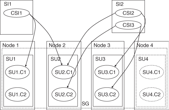
When AMF receives an error report for component C1 of SU2, which has two CSI assignments CSI1 and CSI2, AMF initiates the following actions:
AMF cleans up SU2.C1, and at the same time instantiates SU4. When the cleanup is successful, AMF fails over SI1 to SU3, its next preferred SU, and SI2 to the newly instantiated SU4 by failing over CSI2 to SU4.C1 and switching over CSI3 from SU2.C2 to SU4.C2. When completed AMF also terminates SU2.C2 as shown in Figure 6.13.
Figure 6.13 N-way-active redundancy model example: assignments after recovery.
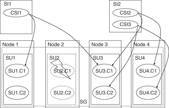
6.3.4.5 Remarks on Redundancy Models
We mentioned earlier and to some extent we have seen in the examples, that the AMF has the concept of preferred assignment distribution. This is expressed through the ranking of the SUs within the SG and also for the N-way and N-way-active models ranking them by each SI. SIs themselves are also ranked within the entire system to ensure that more important services have higher priority to resources when there is a shortage. For example, SIs representing the processing of 911 calls should be ranked higher than those representing other calls.
An additional configuration attribute controls whether AMF automatically re-adjusts the assignment distribution after more preferred SUs become available due to a successful repair, for example. To avoid system ‘oscillation,’ AMF performs such an adjustment only after some probation time has passed and no errors were detected on the repaired components. This probation time applies only to rearrangement of existing assignments. When an assignment was completely dropped and some capacity becomes available for it, AMF assigns it without any delay.
We have mentioned some potential shortcomings of the specification with respect to the redundancy models. They are being looked at as we speak by the SA Forum and also by the implementers of the AMF specification. We included them in our discussion as they are not quite obvious and understanding them help the better understand the overall picture of the AMF and availably management in general. Sometimes describing an error sheds more light on the intricacies than pages of explanations of the correct behavior.
6.3.5 The AMF Administrative Interface
We have seen so far the world of the AMF from the perspective of component developers and the AMF itself. The later view also gave hints about the configuration of an AMF managed cluster and also the information visible about the status of AMF entities and the system as a whole. In this section we take a look at how system administrators can control the system through administrative operations and how the results are reflected in the status information.
6.3.5.1 Administrative Operations
Table 6.4 summarizes the different administrative operations and the AMF entities on which an administrator can issue these operations. Where the operation manipulates any of the states, we also indicated the applicable state transitions as a pair of start and end states separated by slash. In some cases more than one start state is possible, these are listed through comma.
Table 6.4 Summary of the AMF administrative operation and their applicability
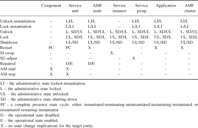
Let's take a more detailed look at each of these administrative operations.
Lock-Instantiation and Unlock-Instantiation
The lock-instantiation and unlock-instantiation operations respectively disallow and allow the instantiation of the target AMF entity and all of its constituents. These operations are applicable to all compound service provider entities as shown in Table 6.5. They change the administrative state of the target entity, which may imply presence state changes of the target entity and some other entities within its scope.
Table 6.5 Applicability of the lock-instantiation and unlock-instantiation administrative operations
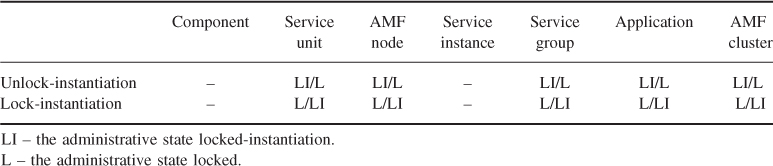
Ultimately AMF instantiates only components, so the instantiation of compound entities is defined as the instantiation of all the components encapsulated by this compound entity. The same applies to the termination of entities.
When the lock-instantiation is applied to a SG, an application or the cluster, none of the constituent components can be instantiated or if they are already in the instantiated state, AMF terminates them as a result of the lock-instantiation.
Without administrative intervention at system startup the AMF selects for each SG of pre-instantiable SUs in the system the set of SUs that makes up the required number of in-service SUs and instantiates them. This selection is based on the SUs' rank within each SG. The administrator issuing the lock-instantiation operation on a SU or an AMF node influences this selection. AMF will not instantiate the target SU or SUs associated with the target node.
Issuing the operation at runtime if the target SU has already been instantiated, AMF will terminate it.
Locking the instantiation of an AMF node will not only terminate all SUs instantiated on the node, but it will also prevent AMF to select this node to host a new SU that was not instantiated before and which is not directly mapped to a node by its configuration. Note however that if such an SU has already been instantiated on the node being locked for instantiation, the SU-node association remains even after the termination of the SU. Currently only cluster restart or reset breaks such an established SU-node association. This restriction may be revised in the future.
The unlock-instantiation operation re-enables the instantiation of the same entities the lock-instantiation prevented.
However when applied to a SU or a node the unlock-instantiation may not immediately result in the instantiation of the target SU or those hosted by the target node. Only if the configuration of the SG an SU belongs requires the SU to be in-service AMF will proceed with the instantiation.
Unlock-instantiation of an AMF node also allows AMF to select the node for hosting new SUs.
Issuing the unlock-instantiation on an SG, an application or the cluster will trigger the instantiation of their constituent entities as performed at system startup. That is, AMF will try to instantiate as many pre-instantiable SUs within each SG of the scope as required to be in-service for the SG.
The lock-instantiation operation is valid only for an entity which is in the locked administrative state. It moves the target entity into the locked-instantiation state. Symmetrically the unlock-instantiation operation is only valid when applied to an entity in the locked-instantiation state and it moves the entity to the locked state.
When these operations are issued on an entity in a state different from the above AMF returns an error.
Lock and Unlock
The lock and unlock operations respectively disallow and allow the provisioning of some service. They are applicable to compound AMF entities as shown in Table 6.6. These operation change the administrative state of the target entity and potentially imply assignment, HA, readiness, and presence state changes for the entities within the scope of the target entity.
Table 6.6 Applicability of the lock and unlock administrative operations
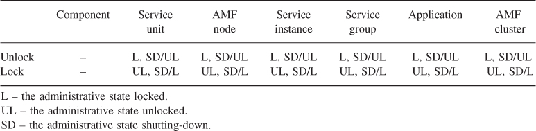
Once all the required service provider entities are instantiated, the AMF starts the distribution of SI assignments. For each SI it determines the number of active and standby HA assignments needed and selects a SU for each of them within the protecting SG. AMF starts the assignment with the SIs of the highest rank and selects the SUs for each according to their affinity to the in-service SUs of their protecting SG.
The lock administrative operation modifies this selection mechanism.
Locking a SI itself means that AMF will not assign it to any SU and if the SI is currently assigned, it will remove its assignments from all relevant SUs. At the same time the administrative state of the SI changes from unlocked or shutting-down to locked. In addition if the SI was already assigned, then its assignment state becomes unassigned and AMF removes the HA states on behalf of the SI and its CSIs from all related SUs and their components.
On the other hand, locking a service provider entity means preventing that particular entity and its constituents from providing services. It depends on the scope of the target entity whether the operation stops the service provisioning altogether or not.
The operation changes the administrative state of the target entity from unlocked or shutting-down to locked. It also changes the readiness state of all SUs and components within the scope of the target entity, which in turn results in removing any HA state they have on behalf of any SI or CSI. This may result in a change of the assignment state of some of the SI.
In particular, locking the AMF cluster, an application or a SG does mean stopping the provisioning of the SIs in the given scope. Since all components and SUs within the scope go out-of-service none of them may take any assignment and any current HA state is removed. Non-pre-instantiable components and SUs are also terminated. For all SIs within the scope the assignment state changes to unassigned.
If the lock is issued on a SU or an AMF node, similar state changes apply but within the SU or SUs of the node only. Therefore AMF will switch-over the SIs assigned to the SU(s) being directly or indirectly locked to other available SUs. Hence the SIs' assignment states may remain as-is or change to partially assigned or unassigned depending on the availability of the required SUs.
The counter part of the lock administrative operation is the unlock operation. It needs to be issued on the same AMF entity as the lock operation to reverse its effects, that is, to allow the provisioning of some services.
Applying the unlock operation to an entity whose administrative state is locked changes its administrative state to unlocked.
If the unlocked entity is a SI, AMF will also try to make on its behalf the required number of assignments to the SUs of the protecting SG. Depending on whether AMF was able to assign all assignments successfully the assignment state of the SI becomes fully or partially assigned.
If the entity being unlocked is a service provider entity the change of its administrative state allows, but does not necessarily result in changing the readiness state of the entity and all the entities within its scope to in-service.
In particular, if the entity is the AMF cluster, an application or a SG, the unlock operation allows the assignment of the SIs to entities of the scope.
AMF will evaluate the status of the entities within the scope of the unlocked entity and if there are SUs whose readiness state evaluates to in-service, AMF starts to assign the SIs of the scope as it would do at system start. This will result in the appropriate state changes: for the SIs the assignment state moves to partially or fully assigned as appropriate. AMF instantiates the non-pre-instantiable components and their SUs as necessary, and all SUs and their components that receive an assignment change their HA state on behalf of the assigned SIs and CSIs.
If the unlocked entity is a SU or an AMF node, the SU's readiness state or in case of the AMF node the readiness state of the SUs hosted on the node may change to in-service depending on the operational and potentially the presence state of their components and the operational state of the hosting node.
Whether a SU which moves to the in-service state will indeed receive assignments from AMF depends on how the current assignments within its SG match the preferred assignments. For example, if there is an assignment for a SI that AMF was not able to assign, the newly available SU will get the assignment. Also if the unlocked SU is more preferred for an assignment than the SU currently serving it, AMF may rearrange the assignments.
In any case, AMF will re-evaluate the SG and the distribution of assignments against the preferred distribution and if necessary it will make new and redistribute existing assignments. Any adjustment will result in the appropriate state changes of the involved entities.
Note that if a compound entity is locked and therefore all the entities in its scope are out-of-service, it is impossible to unlock only a subset of entities in the scope and therefore put this subset back to in-service. The unlock operation needs to be applied to the same entity, which was locked.
Shutdown
The shutdown administrative operation (Table 6.7) is the graceful version of the lock operation and accordingly its interpretation is that it disallows the service of new requests, however it allows the completion of already initiated requests. This is represented by moving the entity on which the shutdown operation was issued to the shutting-down administrative state first and moving it to the locked state once the operation is completed.
Table 6.7 Applicability of the shutdown administrative operation
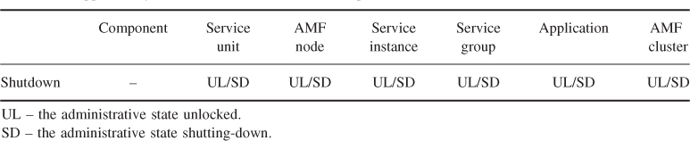
The same way as unlock reverses the effect of the lock operation, it also reverses the effect of the shutdown operation.
When a SI is being shut down, AMF moves the SI's administrative state to shutting-down; however its assignment state does not change. The SUs currently assigned to provide and protect the SI remain assigned, but AMF will change the HA state assignment for those having the active assignment from active to quiescing.
As discussed in Section 6.3.2.3, the components of the SU receiving this assignment change need to reject the service of any new request and complete the service of any ongoing request for their relevant CSI. When no more ongoing requests are left, they need to inform AMF about the completion of the quiescing at which point their HA state for the given CSI transitions to the quiesced state. Once for all CSIs of the SI the components with the quiescing assignments have reached the quiesced HA state, AMF removes all the assignments for the SI and the SI becomes locked. Thus, the SI shutdown operation has completed.
When executing the SI shutdown operation AMF needs to distinguish pre-instantiable and non-pre-instantiable components. One may recall that non-pre-instantiable components are such because they do not implement the AMF API and when started they immediately start providing their service functionality as if they had the active HA state assigned. In other words, their HA state cannot be changed to quiescing and need to be mapped into the active assignment or no assignment.
If there are only non-pre-instantiable components serving the CSIs of the SI, an appropriate mapping is to remove their assignments immediately due to the shutdown operation, that is, to terminate these components. If there are some pre-instantiable components serving some of the CSIs of the SI being shutdown, it is more appropriate to synchronize the termination of non-pre-instantiable components with these pre-instantiable components and therefore terminate the non-pre-instantiable ones only after all pre-instantiable components completed the quiescing.
When issuing the shutdown operation on the AMF cluster, an application or a SG, it has a similar effect as described above on all the entities in the scope. However the administrative state changes to shutting down only for the entity on which the operation was issued.
The SUs and their components having the active HA state for any of the SIs within the scope receive a new quiescing HA state assignment for them, the completion of which they report back to AMF. At completion AMF sets the states and performs the operations as appropriate for the administrative lock.
The SIs of the scope remain partially or fully assigned until the SUs assigned in the active HA state complete the quiescing. After this they become unassigned.
Issuing the shutdown operation on a SU or an AMF node is peculiar and requires attention.
If the target SU or any SU hosted on the node has any active HA state assignments, AMF changes them to the quiescing HA state. If these are the only active assignments for some SIs, this change of the HA state assignment effectively shuts down not only these SUs, but these SIs as well as AMF performs no switch-over at this moment.
As the components of a SU complete the quiescing and report back to AMF this fact, their HA state for their CSI changes to quiesced. When for all CSIs of a SI the components moved to the quiesced state AMF finally switches over the SI to another SU. It will do so because the SI was not the target of the shutdown, it targeted the serving SU only. The SI is in the unlocked administrative state and now with the completion of the quiescing its assignment state becomes unassigned as all its assignments are now quiesced. Thus, if there is another SU available for serving the SI, AMF will assign to that the active HA state on behalf of the SI and the SI will be served again.
As mentioned earlier the unlock administrative operation reverses the effects of the shutdown operation. Once it is issued on an entity, the entity's administrative state changes to unlocked and AMF reverses back the quiescing HA state assignments to active for all the SIs in the scope. Since the quiescing is equivalent to the active assignment this implies no other state changes.
If some entities within the scope have already completed the quiescing, AMF applies the same action as if the unlock operation was reversing the lock operation.
Restart
The administrative operations discussed this far were manipulating the administrative state of the target entities. The other state changes were the result of this manipulation. The restart administrative operation does not impact the administrative state of an entity. The restart administrative operation initiates a presence state cycle on instantiated AMF components and SUs within the scope of the AMF entity on which the restart operation was issued (Table 6.8).
Table 6.8 Applicability of the restart administrative operation
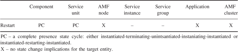
As a result of the restart operation, AMF will drive the presence state of the components of the given scope through the instantiated-terminating-uninstantiated-instantiating-instantiated or the instantiated-restarting-instantiated cycles depending on the restartability of the components as discussed in section ‘Component Presence State’. Whether one or the other cycle applies will also determine how the readiness state of the SU is impacted which in turn determines the way the assignments are impacted during this procedure.
The actions AMF will perform to achieve the restart of a component are:
- First AMF will terminate the component via the API or by the terminate CLC-CLI command. If this fails AMF will do the cleanup to achieve at least an abrupt termination.
- If the termination was successful, next AMF will instantiate the component using the CLC-CLI or the API depending on the component category. If successful the component returns to the instantiated presence state.
If the target of the restart administrative operation is a single component and the component is restartable, then the operation triggers the instantiated-restarting-instantiated presence state cycle. The component moving to the restarting state does not change the presence state of its SU, hence it does not trigger a readiness state change and the component can keep all its assignments.
Note however that from the component's perspective—considering an SA-aware component—the procedure is the same whether the component is restartable or not and constitutes the following steps:
- AMF calls back the component removing the assignment;
- AMF calls back to terminate the component;
- AMF instantiates the component via the CLC-CLI (or API for contained components);
- the component registers with AMF;
- AMF assigns an assignment, which for a restartable component will be the same that was removed in the first step.
If the target component is nonrestartable, it needs to go through the instantiated-terminating-uninstantiated-instantiating-instantiated cycle. As soon as the component is terminating, the pre-instantiable SU's presence state changes to terminating as well, which in turn changes its readiness state. Thus, all the assignments of the entire SU need to be switched over to their appropriate standby.
The restart operation has similar effect when its target is a SU. AMF performs the SU restart by restarting all of its components. It is the restartability of the components that determines whether switch over happens or not. During the restart AMF also takes into account the components instantiation order.
When the operation is performed on the AMF cluster, an AMF node or an application, AMF guarantees that first all components of all the SUs within the scope are terminated. It starts their re-instantiation only after the successful termination.
At AMF node restart AMF switches over the SIs as necessary for each of the SUs. For the cluster and for application it performs no switch-over.
As we have seen the restart administrative operation acts only on AMF entities. In particular the administrative restart of the AMF cluster or an AMF node is different from the cluster reset and node failfast recovery actions as AMF executes the later ones at the execution environment level.
Even at the level of the AMF entities, the restart recovery operation involves the abrupt termination of the components while the administrative restart does not. This means that in the second case a component may save some state information that can be picked up by the new incarnation of the same or another component. Hence, the restart administrative operation may not be appropriate for repair.
SI-Swap
The SI-swap administrative operation can only be initiated on a SI in the partially or fully-assigned states (Table 6.9), which is protected according to a redundancy model that includes active and standby HA state assignments and at least one assignment is available for both HA states. An assignment in the quiescing state is equivalent to an active assignment.
Table 6.9 Applicability of the SI-swap administrative operation
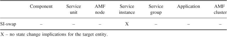
As a result of this operation AMF switches the HA state assignments for the SI between the SUs having the active and the standby roles. Namely, the SU having the standby assignment becomes active and the active becomes the standby after a successful swap.
As a side effect, the assignments of other SIs may also be swapped or re-arranged. In particular, since the 2N and the N+M redundancy models require that an SU may have only assignments in one role, it has to be either active or standby for all the SIs it provides or protects, swapping the assignment for one SI will trigger the swapping of all SIs that are assigned to the active SUs, it may redistribute other assignments.
In case of N-way redundancy the active assignment is swapped with the highest ranking standby assignment. Due to capacity limitations additional rearrangements may happen.
SG-Adjust
The SG-adjust administrative operation gives the administrator the possibility to rearrange the distribution of the SI assignments within a SG in a way that best matches the preferred distribution (Table 6.10).
Table 6.10 Applicability of the auto-adjust operation
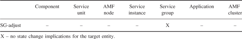
There are two configuration attributes that define the preferred distribution of assignments:
Within a SG SUs are ranked and this ranking provides AMF with the hint which SUs should be brought into service first when not all configured SUs need to be instantiated. If no other attribute applies, the SU ranking also indicates which SUs should get assignments first. Namely, the highest ranking SUs should receive the active assignments in an SG, followed by those getting the standby assignments if applicable. For example, in a 2N SG the ranking of SUs may make up the following list: {SU1(1), SU2(2), SU4(3), SU3(3)}. In parenthesis we indicated the rank value for each SU; note that they may be equal. AMF will instantiate the highest ranking SUs first up to the configured number of in-service SUs, let's say 3, for example, SU3 remains uninstantiated. The choice between SU3 and SU4 is up to the AMF implementation. Then AMF will try to make the highest ranking SU1 the active SU and the next highest ranking SU2 the standby. The third instantiated SU remains unassigned.
If the administrator locks the node of SU1, for example, for some maintenance purpose AMF will switch-over the active assignments of SU1 to SU2 and make SU4 the new standby. It will also instantiate the last SU3 to have three SUs in-service.
When the administrator unlocks the node where SU1 resides, the assignments remain as above unless the SG is configured for auto-adjust. The administrator can use the SG-adjust operation to return to the initial distribution of assignments. That is when issued, AMF will move first the standby assignment to the now available SU1 and then perform a swap between SU1 and SU2 for all the SIs. It will also terminate SU3 or SU4.
For N-way and N-way-active SGs, in addition to the global ranking of SUs a per SI ranking may be given.
In fact, if the SUs have different ranks within the SG one would like to provide the per SI ranking to distribute the load among the SUs as by default the SU rank would be used by AMF which means that all SIs will prefer the same SUs and AMF will assign all the active assignments to the highest ranking SUs up to the capacity limit. To avoid such an overload one may want to configure the per SI SU ranking with load distribution in mind, for example, as presented in [80].
The operation has no impact on SGs that are configured for automatic adjustment as for these AMF continuously maintains the preferred distribution.
Repaired
The only way AMF attempts to repair its entities is by restarting them. If restart in not a remedy for the fault causing the errors these restarts turn out to be futile and after some configured number of instantiation attempts or if the termination-failed presence state is reached AMF will give up the repair and mark the entity disabled. The configuration may limit the escalation to fail-fast or completely forbid AMF to do any repair attempts, when it is known to be useless or it may even be harmful as discussed in section ‘SU Operational State’.
At this point it is left to the administrator (or some maintenance operations) to repair the entity and re-enable it, so AMF can take over its control again.
The repaired administrative operation allows an administrator to do just that: declare that an AMF entity, more precisely a SU or an AMF node and all its constituents have been repaired so AMF can take them back into its control (see Table 6.11). The administrator needs to ensure that none of the components of the SU or none hosted on the node is running, that is, the presence state of all components in the scope is uninstantiated.
Table 6.11 Applicability of the repaired administrative operation
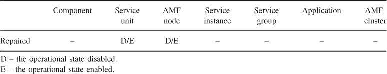
The direct result of the operation is that AMF transitions the operational state of the target entity and any of its constituent entities from disabled to enabled. It also moves the presence states for all the components and SUs in the scope to uninstantiated. AMF does not validate if either of these state changes are indeed appropriate.
These state changes potentially make these entities available for instantiation and assignments. Therefore AMF will evaluate whether any of the newly available SUs need to be instantiated, for example, to make up the configured number of in-service SUs or if it is a preferred SU compared to any of those currently instantiated. Next AMF evaluates if any of the assignments need to be changed or an unassigned SI can be assigned again with the newly available capacity. If yes, AMF will perform the rearrangements.
EAM-Start and EAM-Stop
The EAM-start and the EAM-stop administrative operations allow the administrator to activate and deactivate the EAM of a particular component or all the components of a SU. That is, those for which the am_start and am_stop CLC-CLI commands exist in the configuration as indicated in Table 6.12.
Table 6.12 Applicability of the EAM-start and EAM-stop administrative operations
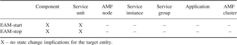
As mentioned in Section 6.3.2.6 when AMF instantiates a component it also initiates its EAM if the am_start CLC-CLI command is configured for the component. Normally this active monitoring will continue as long as the component is instantiated. This is unlike the healthcheck (also referred sometime as internal active monitoring) or the passive monitoring, which both start and stop as a result of API requests.
In case of EAM the administrator is given the control to stop and start the monitors. AMF maps the EAM-start administrative operation to the am_start CLC-CLI command of the target component or the components of the target SU and executes them. Similarly, it maps the EAM-stop operation to the am_stop CLC-CLI command.
If the EAM-start operation is invoked for a component whose monitor is already running, its status will not change and it remains running. This is important as in the AMF information model there is no object or attribute reflecting the status of external active monitors. In fact, an AMF implementation is not even required to know whether an external monitor it has started at component instantiation is still running. If it has failed, the EAM-start administrative operation provides the means to restart such failed monitors.
6.3.5.2 Administrative State of Compound Entities
As we have seen from the sections on the different administrative operations, the administrative state is defined for all compound AMF entities. The values the administrative state may take and their meaning depends on whether the entity is or includes provider entities or it is on the service side.
On the service provider side the administrative state has the following values:
- Unlocked – the entity itself is not blocked administratively from participating in the provisioning or protection of some SIs. AMF may select the entity for an assignment provided all other necessary conditions are also met, that is, the readiness state of components and SUs is in-service.
- Locked – the entity and all its constituents are administratively prevented from participating in service provisioning or protection. AMF may not select any SU within the entity's scope for any service assignment. Moreover within the entity's scope AMF has removed any existing assignment. If the locked entity encapsulates all SUs that may provide a particular SI, locking this provider entity implies the suspension of the provisioning of the service represented by the SI.
- Shutting-down – the entity and all its constituents are administratively prohibited from taking new SI assignments and asked to remove gracefully any existing assignment. AMF may not select the entity or any provider entity within its scope for any SI assignment. For the existing assignments AMF changes the HA state assignment from active to quiescing by calling back the appropriate components. Shutting down the provider entity may result in the graceful shutdown of the service provisioning for some SIs. However the provisioning may resume after the completion of the shutdown if the entity does not encapsulate all SUs that may provide a particular SI. In other words when the SU becomes locked AMF switches-over its SIs.
- Locked-instantiation – the entity and all its constituents are administratively prohibited from instantiation. AMF will not instantiate any component or SU belonging to the scope of the entity and it terminates any currently instantiated entity.
These values are used in the above meaning for SUs, AMF nodes, SGs, applications, and the AMF cluster.
SIs belong to the service side and for them the administrative state has the following valid values and interpretation:
- Unlocked – AMF may assign the HA state on behalf of the SI. In fact if there is any in-service SU available for assignment and if all dependencies are met for the SI, AMF will try to assign it in the active and if possible and required in the standby state as well.
- Locked – AMF does not assign an HA state on behalf of the SI to any SU and it has withdrawn any existing assignment. AMF has removed all CSI assignments for the SI from all components regardless what HA state assignment they had.
- Shutting-down – The service represented by the SI is being gracefully removed therefore AMF has changed the existing CSI HA state assignments for the SI from active to quiescing by calling back the appropriate components. Once the quiescing is completed by a component for a CSI, AMF will remove the CSI assignment completely.
It is important to understand that the effects of an administrative operation do not propagate through the administrative state. The operation changes the administrative state of the target entity only. The effects propagate via the readiness state, which is a cumulative state for all those entities where it is defined (see section ‘Component Readiness State’ for the components and section on the SU readiness state).
This allows a better bookkeeping of the intended administrative states of different entities in the system. Imagine a SU within a SG. If one locks this SG first and then the SU within the group, the two lock operations are kept independent as each represented by its own attribute: one in the SG and one in the SU. The unlock operations can be done independently: unlocking the SG will not unlock the SU. If the effects of the locked administrative state were propagated through the administrative state this would not be possible.
The other nuance that requires some attention is that the administrative state represented by a persistent runtime attribute of the appropriate classes of the AMF information model even though the state changes are triggered by the administrator. This may be different from the approach used in other systems. The persistency of the attribute ensures that even if the system is restarted a completed administrative state change will survive the restart. Using the same mechanism that keeps this value the initial value for the administrative state can be configured when the configuration object are created for the different entities.
AMF sets the administrative state as it executes the actions associated with each administrative operation. It is not mandated by the specification whether an AMF implementation does so at the initiation of the administrative operation or at completion. Therefore it depends on the implementation when the state information is persisted so it will survive a cluster reset, for example.
6.3.6 Interactions Between AMF and Other AIS Services
6.3.6.1 AMF Interaction with PLM
As we have seen the AMF is required to perform the node fail-fast and cluster reset recovery actions on the level of the execution environment. For this purpose AMF should use the PLM [36] administrative API, which provides the appropriate abrupt restart operation and which also has the information how this should be performed for each particular execution environment.
For example, if the execution environment is hosted directly on the physical hardware the abrupt restart is mapped by PLM into a reset of this hosting hardware element. If on the other hand the execution environment is a virtual machine running in a hypervisor, PLM maps the operation into the appropriate operation of the hypervisor.
The identity of the execution environment that needs to be restarted to execute a fail-fast operation AMF needs to obtain from the mapping information for the CLM node hosting the AMF node.
The AMF is not required to have any further interaction with PLM, however ideally, it is aware to some extent of the PLM information model because it provides the information how the AMF nodes map onto the physical nodes providing the platform for the cluster. With the widespread use of virtualization the mapping is not 1 : 1 any more. This means that the failure of a physical node may take out of service a number of AMF nodes. Therefore it is beneficial if AMF can avoid putting all its eggs into the same basket—so to speak. That is assign SUs of the same SG to AMF nodes that map to different physical nodes.
AMF can be helped in this task by a configuration that takes into account this consideration and let's say groups AMF nodes into node groups based on their mapping to hardware elements.
6.3.6.2 AMF Interaction with CLM
The AMF uses the membership information provided by the CLM [37] to determine the scope of the AMF cluster. As described in section ‘SU Readiness State’, one of the pre-requisites to have an SU readiness state in-service is that the AMF node of the SU needs to map to a CLM node which is currently member of the CLM cluster. Moreover, an AMF implementation is required to terminate any component of an AMF node the CLM node of which is not currently member of the cluster (see section ‘The AMF Node’).
All this implies that the AMF needs to obtain the cluster membership information and track its changes to determine which AMF nodes map at any given moment to CLM member nodes.
Through the tracking the CLM provides not only the changes that have occurred already, but since the introduction of the PLM [36] also the planned at the PLM level changes. Such a planned change is provided as a membership change proposal to the AMF that it can evaluate from the perspective whether it would cause any service outage or not considering the current status of the system. If the conclusion is that indeed the change would result in dropping of the active (or equivalent) assignments for some of the SIs, AMF rejects the change. This informs the initiator that service outage can be expected.
At the current state of affairs, AMF does not provide any further information on exactly which SI would be dropped and considering the complexity of the evaluation and that the result partially depends on the AMF implementation another entity cannot replicate the same result.
There is a proposal for AMF to provide this missing information in one way or another as in some cases this can provide a better justification whether to proceed or abandon a particular operation.
6.3.6.3 AMF Interaction with NTF
The AMF uses the Notification service (NTF) [39] to emit alarms and notifications pertinent to the system status. Doing so it also correlates notification ids, that is, if the notification or alarm is generated as a consequence of an event for which AMF is aware of the id of any previously generated alarm or notification AMF puts the correlated parent, root, and any other known notification ids in the appropriate fields of the generated notifications. On request AMF also provides these correlated notification ids through the API.
The alarms generated by AMF indicate emergency situations that may require immediate administrative intervention from AMF perspective as it cannot resolve a problem, which may already impact the availability of some services.
AMF Alarms
The AMF generates alarms for the following situations:
- Cluster reset triggered by a component failure
Any time the AMF receives an error report it contains a recommended recovery action and after verifying the authority of the source of the error report AMF performs the recommended recovery, which may require a cluster reset. This alarm is generated by AMF in such a case.
AMF clears the alarm automatically after the successful execution of the cluster reset.
The alarm indicates outage for all services provided by the system.
- SI unassigned
The AMF generates the SI unassigned alarm any time it cannot find the required capacity to assign a SI within the protecting SG or if the provisioning of the SI is prevented administratively. That is, the alarm indicates that the SI assignment state has become unassigned, which means that the associated service functionality is not provided.
AMF clears the alarm automatically as soon as it can again partially assign the SI to at least one SU.
- Component cleanup failure
AMF has a single attempt to clean up a component: it uses either the cleanup CLC-CLI command or if the component life-cycle management is mediated through a proxy or a container, it asks the mediating component to clean up the component. If the cleanup operation fails the component enters the termination-failed presence and disabled operational states. At the same time the encapsulating SU also moves to the termination-failed and disabled states and it cannot be used any more for service provisioning or protection. Depending on the node configuration AMF may escalate the failure to a node fail-fast operation otherwise it has no other means to terminate the offending component. In either case it informs the administrator about the situation by issuing the component cleanup alarm.
If the component had an active assignment for any CSI at the moment the failed cleanup was issued, these CSIs and their encapsulating SIs cannot be assigned to any other SU until this alarm condition is cleared. Hence in such a case there is a service outage associated with the alarm.
The alarm is cleared by the AMF after it receives a repaired administrative operation targeting the disabled SU.
Alternatively the alarm is automatically cleared after a successful restart of the execution environment the AMF node is mapped to.
- Component instantiation failure
Whenever AMF exhausts all the instantiation attempts permitted by the configuration it moves the component to the instantiation-failed presence state and disables its operational state. As a result the SU encapsulating the component also moves to the instantiation-failed and disabled states and none of its resources can be used for service provisioning or protection. As in case of the termination failure AMF may or may not be allowed to repair the error by initiating a node fail-fast action. In any case it issues the component instantiation alarm to inform the administrator. Depending on the available redundancy, this alarm may or may not indicate service outage.
The alarm is cleared by the AMF after it receives a repaired administrative operation targeting the disabled SU.
Alternatively the alarm is automatically cleared after a successful reboot of the execution environment the AMF node is mapped to.
- Proxy status of a component changed to unproxied
The AMF generates this alarm whenever it could not assign the active assignment for the proxy CSI to a proxy component for an already instantiated proxied component or if all mediation attempts of the existing proxy component have failed. At this point AMF is in the dark regarding the actual status of the proxied component as AMF makes no assumptions about the state of the proxied component resulting from the failure of its proxy component.
This alarm indicates a service outage with respect to the proxying functionality. However this may or may not indicate service outage with respect to services provided by the proxied component.
The alarm is cleared by the AMF after it receives a repaired administrative operation targeting the SU of the proxied component, since this implies that the proxied component is in the uninstantiated state.
Alternatively the alarm is automatically cleared after AMF successfully assigns the proxy CSI to a proxy component that registers on behalf of the proxied component.
AMF Notifications
In addition to updating the AMF information model with state information of all AMF entities, the AMF also generates a notification for any state change. These notifications may provide extra information on the circumstances pertinent to the change. For example, if the SU whose operational state changed to disabled has been upgraded and therefore its maintenance campaign attribute contained a reference to the running upgrade campaign AMF includes the name of the campaign in the notification. Other services such as in this case the SMF can pick up this extra information and take corrective measures as necessary.
Besides the state change notifications AMF also generates a notification each time it engages successfully a new proxy component in proxying a proxied component.
6.3.6.4 AMF Interaction with IMM
The Information Model Management service (IMM) [38] provides the administrative interface for all AIS services including the AMF.
All the administrative operations discussed in Section 6.3.5 are issued using the Object Management interface of IMM (IMM OM-API), which provides a function to invoke administrative operations on different objects of the system information model and delivers these administrative operations to the service implementing those objects in the system.
At system start up the AMF obtains its initial configuration from IMM, which loads the complete system information model from an external source such as an XML (eXtensible Markup Language) [81] configuration file or a repository. This configuration file or repository includes the AMF information model as well.
An AMF implementation also registers with IMM as the object implementer for the AMF information model portion of the system model. It does so in all available roles. From that moment on IMM will deliver to AMF the administrative operations initiated on any of the objects in the AMF information model and also any changes made to the model.
Once the system is up and running the AMF information model can only be changed through IMM.
The same way as IMM exposes the API for administrative operations it also provides the API for populating and changing the information model. Through this API an administrator may create, modify, and delete objects of the classes defined by the specification and implemented as part of the particular AMF implementation of the target system.
The information model (via the IMM OM-API) is also the interface through which the system status can be monitored by an administrator as the AMF—in the role of the runtime owner of the different object of the AMF information model—is required to update the runtime attributes in the model as appropriate.
6.3.6.5 AMF Interaction with SMF
Going through directly the IMM OM-API for all the changes necessary to perform a system upgrade, for example, may be rather cumbersome and error-prone. Therefore a different approach is provided for the SA Forum systems: the configuration changes can be deployed is via upgrade campaigns executed by the SMF [49].
In the background SMF also uses the IMM OM-API to communicate with the AMF. It acts as a management client to AMF driving the administrative operations and model changes necessary for the upgrade through the Object Management interface of IMM.
SMF allows an orchestrated execution of configuration changes through well defined methods that drive toward the reduction of service outages during upgrades. The SMF synchronizes all aspects of an upgrade necessary to make it successful and least intrusive: the administrative operations toward AMF are coordinated with the software installation and removal procedures and with the model changes. All of which is backed up with mechanisms that allows system recovery should any problem occur during execution.
As an input SMF expects an upgrade campaign specification. This whole campaign specification is pre-calculated and provided to SMF, which then ensures the orderly execution of the changes required for the deployment.
For some details on how to come up with an AMF configuration and the way it can be upgraded please consult [82], which uses an example to demonstrate some basic concepts.
Besides the interaction via the IMM OM-API, AMF also provides feedback on potential faults introduced by an ongoing upgrade campaign via the NTF. The SMF subscribes for state change notifications generated by the AMF to detect errors potentially introduced by the upgrade campaign and to initiate the necessary recovery actions.
6.3.7 Open Issues
Throughout the discussion in this chapter we indicated many issues that today are left to an implementation of the AMF because they are not or just partially addressed by the specification.
One of the main issues that we did not mention is the dynamic configuration changes that AMF managed systems need to go through during their long life-cycle. There are regular software updates that need to be deployed, patches need to be applied and also the service functionality changes; it has its own life-cycle. Some of the related issues are addressed in the chapter about the SMF, however there is the AMF side when and how the AMF applies the changes is still open to a great extent at the time of this book being written. This is a somewhat long-term debt of the SA Forum Technical Workgroup, and these issues are being discussed as we speak. They should become part of the next upcoming release.
When it comes to the upgrade of the service functionality it is much less clear whether standardization is possible, to what extent and how much of that should become part of the AMF specification. Maybe the solution is to come up with some patterns like the redundancy models that define some policies that AMF will follow and it becomes to the application designers' responsibility to use the appropriate for the service functionality pattern.
With all that the AMF specification is considered to be one of the most mature within the AIS. Although it is always possible to come up with tricks and tweaks to the specification, these do not change its essence, which can cover the needs of a wide range of applications.
6.3.8 Recommendation
The AMF is the corner stone piece in the SA Forum specification set as it addresses SA itself. It is the answer of the SA Forum for any application that needs to provide services in a highly available fashion.
However, the way AMF is defined it is not restricted to applications that have this need. It can provide life-cycle management for applications that do not implement any of the API functions and not aware of SA at all. At the same time when it can manage applications using sophisticated load sharing schemas, embedded in other execution environments, or not part of the cluster at all.
The flexibility of the AMF information model allows an easy mapping of this wide range of applications and results in a uniform view of the entire system easing system administration and management.
6.4 Conclusion
This chapter introduced the SA Forum AMF.
First we looked at concepts visible through the AMF API and therefore the main concerns for application developers when integrating their design with AMF. These concepts are the component and the CSI. They introduce the logical division of AMF controlled entities into the groups of the service provider entities and the provided service entities.
The AMF performs the availability management based on a model composed of logical entities that represent these two groups. It ensures the HA of the entities representing the provided services through dynamically assigning them for provisioning and protection to the redundant service provider entities in the system. The AMF API is the means AMF uses for this dynamic assignment management. Therefore we looked at the HA states a component can be assigned to on behalf of a CSI; the interpretation of these states and their implications on an implementation of components.
The AMF is capable of managing components that use software implementations that were not developed with the AMF API in mind. AMF can manage them directly as non-SA-aware-nonproxied components or if they at least implement the HA states then using a proxy to mediate the control operations.
Next, to familiarize the logical view that AMF uses for availability management we discussed the AMF information model and its organization. We have seen that components have two types of collaboration and accordingly there are two groupings:
Components that closely collaborate to make up a service functionality desired by the users are grouped into SUs. The service functionality at this level is represented by a SI, which is the combination of the CSIs provided by the single components.
Similar SUs that are redundant in order to protect the service functionality form a SG. Within a SG components of different SUs cooperate to provide availability for their protected service. The role the different component and SUs take in this collaboration is managed by the AMF based on the policies defined for the particular redundancy model implemented by a particular SG.
We compared the main features of the different redundancy models using a simple failure scenario in a relatively simple configuration that still reflected the key points site designers would want to consider when configuring their site.
We also looked at the information model from an administrative perspective as the model contains the status information of the AMF entities in the system and administrative operations are issued on the objects of this model representing these different entities. We have seen how AMF calculates the readiness state of SUs to determine the right candidates for service assignments and how administrative operations impact the readiness state through the administrative and presence states.
The IMM mediates all the administrative operations and information model changes toward AMF.
The chapter also touched upon the interactions of the AMF with other AIS services in the system. Namely it uses PLM for some error recovery operations, tracks the cluster membership changes via the CLM API and generates notifications.
We could not cover all the details and intricacies of the AMF considering that the specification itself is well over 400 pages today. Our goal was to give a different perspective to the specification, which hopefully provides an easier entry point to it, to explain and demonstrate some considerations that drove the solutions of the specification, so one can understand these solutions better and also close the gaps in areas that are left open or not fully defined by the specification.