
Resource Management in Pervasive Computing
Pervasive computing encompasses a broad range of capabilities including communications (e.g., cell phones), mobile computing (e.g., laptop computers), image transferring (e.g., displays), and sensors (e.g., RFID and cameras), where efficient resource management is important for making pervasive systems available anytime and anywhere in the world. More specifically, infrastructures and challenges, from resource allocation to task migration, must be carefully maintained in order to make pervasive systems more efficient.
In this chapter, we introduce ways to allocate resources efficiently and then present how to migrate tasks intelligently in pervasive environments.
4.1 Efficient Resource Allocation in Pervasive Environments
In the current pervasive computing environment, more and more microprocessors with extremely limited resources will be embedded into pervasive devices [1]. We call these devices processing elements (PEs) because each PE only has a limited function. Accordingly, all PEs form a pervasive multiprocessor (PMP) system [2,3]. Different kinds of PEs have different functions, and several kinds of PEs can work together to complete a complex task.
There are many kinds of PEs in a PMP system. The objective of PMP systems is to organize heterogeneous PEs in order to run pervasive applications across the PEs. Therefore, resource allocation is a key issue that must be solved before these PMP systems can be put into practice.
In the following section, we will introduce two kinds of resource allocation policies as part of a detailed introduction to PMP systems.
4.1.1 Introduction to PMP Systems
In the pervasive society, services are filled around the user as easily as oxygen is supplied. This requires computing resources with two opposing attributes: higher performance and lower power consumption. A PMP system consists of many PEs and provides various functions for users by combining certain specified PEs. In the pervasive society, users’ needs are multifarious so that the best solution is to offer several basic functions that can collaborate with others to provide various services. This idea brings flexibility dynamics to a PMP system.
In a PMP system, there are three kinds of nodes, as shown in Figure 4.1.

Figure 4.1 A pervasive multiprocessor system.
■ Client node. This node requests tasks for mobile users through mobile terminals in a wireless network.
■ Resource router (RR). This is a gateway of the PMP system. There exists only one RR node in one subnet. The RR node receives task requests from the client nodes and determines which tasks should be currently executed in the subnet.
■ Calculation node. This executes tasks from the client nodes. When a task is executed, several calculation nodes are connected to each other like a chain. To encode a bitmap file into a JPEG file, for example, six calculation nodes are organized as a chain. Application demands determine which calculation nodes will be combined.
The core components of PMP systems are illustrated in Figure 4.2, and they interact as follows. First, in user space, a pervasive application sends a task to task management via a ubiquitous service broker (USB). Then, task management asks the task analysis and decomposition component to decompose the task into small subtasks. Each subtask can be completed by a corresponding PE. After decomposing, the task layer sends the subtasks to the service layer. Components in the service layer will require PEs from the resource layer and will schedule the PEs for subtasks. The resource layer is responsible for managing PEs, including monitoring PE status.
The PMP system works in the following way. A client uses a mobile phone to take a photo, which is in raw form and takes up a large space. Then the pervasive application on the mobile phone connects to the RR node via a fixed UDP port. After connecting, the RR spawns a new client thread to communicate with the client (here, this refers to the mobile phone) for the current task. Then the mobile phone sends the task (here, this refers to JPEG encoding) and decomposed subtasks to the new client thread. The new client thread finds all the necessary PEs for these subtasks. If it cannot find them all, it rejects the task. If it finds them all, it sends the subtasks to the PEs, and any of these PEs cannot be allocated again for other tasks until all of these PEs are freed by the system. Finally, the PE in the last step sends the result to the mobile phone.
4.1.2 Pipeline-Based Resource Allocation
The primitive resource allocation scheme in PMP systems does not release all reserved PEs until the whole task is finished, which causes a huge waste of computational resources. To mitigate such a limitation, we designed two pipeline-based algorithms: a randomly allocating algorithm (RAA) and an RAA with cache (simplified as RAAC), in which the RR only allocates a necessary PE during the current phase. First, we review the primitive resource allocation algorithm (i.e., the current algorithm, or CA) as follows.

Figure 4.2 Architecture of PMP systems.
In the CA, when a task arises, the RR will reserve all the PEs needed for the task. During the processing, all allocated PEs cannot be used by other tasks even when they are free. In the CA, the total delay can be calculated as follows:
(4.1) |
where m is the number of tasks that RR can handle at one time, and t is the time to handle the m tasks. So, the ith m tasks wait (i−1) time units.
Task execution efficiency can be formulated as follows:
(4.2) |
where f refers to task execution efficiency, ei (1≤i≤n) is the execution time in ith PE, and cj,j+1 is the communication time between jth PE and (j+1)th PE, 1≤j≤n.
To improve the task execution efficiency in CA, we design an RAA. The basic idea of an RAA is that after the PE is finished executing the process, the PE will ask the RR for the next phase. Task execution efficiency can be formulated as follows:
(4.3) |
where ei (1≤i≤n) is the execution time unit, cri (1≤i≤n) is the communication time between ith PE and RR, and ci−1,j (2≤i≤n) is the communication time between (i−1) th PE and ith PE.
For mobile users, the battery lifetime is a very important factor in the system design. To reduce the energy consumption on the user side, we adjust the first PE and the last PE to provide frequent access for the user to search for the last PE. Thus, all the optimization process has an effect on the middle PEs in the whole process chain.
In the RAA algorithm, the usage rate of a PE is quite high, but the load in the RR is heavy. To reduce the load in the RR, we introduce a cache technology and design, the RAAC algorithm, where we assign a cache for every PE to memorize the next stage’s PE. When a PE finishes its subtask, it will search the next phase of PE in its cache. If all PEs in the cache are at a busy status, it will ask RR to assign one free PE as the next phase PE. In this algorithm, task execution efficiency will become
(4.4) |
where ei (1≤i≤n) is the execution time unit, cri (1≤i≤n) is the communication time, and ci−1,j (2≤i≤n) is the communication time between (i−1)th PE and ith PE.
In resource allocation for PMP systems, another important concern is how to allocate PEs when there are no available qualified PEs because each PE is deployed for a specified kind of task (e.g., JPEG encoding). In addition, although all users request the same tasks, there are not enough available PEs, and some of the requests are rejected. To solve this problem, we designed the following two kinds of PEs: available PEs and empty PEs. An available PE executes a specified code only for a corresponding subtask. In order to complete a task, a group of available PEs is combined for all the subtasks in a task. On the other hand, an empty PE itself does not carry any code; however, it can load any kind of codes from a repository PE or a repository server so that it can perform any corresponding subtask.
We utilize empty PEs when we cannot find any available PE, when available PEs are all busy, or when they cannot deal with a requested task. In summary, PEs can be allocated for handling a diversity of tasks as follows.
1. Discover a set of available PEs. (This does not mean they all are allocated at one time, this is just for testing the requirement.) If all are found, that is fine; otherwise, if all cannot be found but there are empty PEs, proceed to Step 2. Otherwise, reject the task.
2. Ask the system for necessary codes, if the codes are loaded to empty PEs, go to Step 3.
3. Ask the client for necessary codes (this is handled by the pervasive application and is unseen by any user), if the codes are loaded to empty PEs, go to Step 4.
4. Check if the task is a migrating task; if so, borrow the code from the last location; if not, reject the task.
Users are unaware of the above steps. So, the users experiment with better performance without being rejected by the system.
We built a simulation system to evaluate the aforementioned three algorithms with a Poisson distribution [4] based task arrival ratio. The Poisson distribution is applicable to various phenomena of a discrete nature whenever the probability of a phenomenon happening is constant in time or space. The number of tasks is from 2500 to 5500. We run the simulation of the number of tasks from 2500 to 5500 every 150 intervals. We set the number of PEs as 2400. Each task needs six PEs to process the six JEPG encoding steps, respectively. Therefore, the total number of PE chains is 400. We also set the network delay as 100.
Figure 4.3 shows the load balance in RAA and RAAC schemes. The load balance of CA is obviously smaller than that of the RAA and the RAAC because once the RR assigns the PE to execute the task, it will never communicate with the PEs. From this image, we can see that, by using the cache technology, the load balance in the RAAC has a better result than that of the RAA. The reason is that almost every time the PE should ask the RR for the next phase PE.
Task execution efficiency greatly depends on waiting time. As shown in Figure 4.4, CA shows the worst result because it has to wait for the execution to start even though there are free PEs in the process chain. The RAA outperforms the RAAC; however, it has a serious load balance problem.

Figure 4.3 Load balance in RAA and RAAC.

Figure 4.4 Tasks’ execution efficiency in CA, RAA, and RAAC.
Delay (waiting time) is an important factor in a real system. Even if the total execution time is good, if the delay is very large, the system still is not efficient for users. From Figure 4.5, we can see that the average of CA delay is extremely large. That is because the execution procedure is almost sequential. The reason why the RAA is slightly better than the RAAC is the RAA can fully randomly use the next phase of PE. Therefore, the waste from failed communication time is omitted.
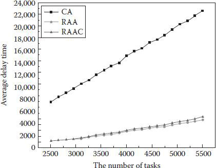
Figure 4.5 The delay (waiting time) in CA, RAA, and RAAC.
Through these experiments, we have successfully proven the value of our proposed algorithms. Considering these key factors (task execution efficiency, load balance of the RR, the delay of task execution), the RAA and RAAC have both merit and demerit. There is always a trade-off between these factors. Taking into account the balance point of all factors, we found the RAAC is much more suitable in the real environment for allocating resources (PEs) when the system has many users and many tasks to process. If the users and tasks are not that large, the RAA could perform well, too. One other thing we have realized through these experiments is that we can set the allocating policy flexibility based upon the user’s requests.
4.1.3 Probabilistic Approach-Based Resource Allocation
To further improve the efficiency of resource allocation in the aforementioned PMP systems, a probabilistic approach can be adopted, which makes the PMP system able to look for an item that needs to be processed earlier and more efficiently. Moreover, it can omit a useless retrieval that causes a waste of energy.
First, in the following steps, we introduce the basic algorithm through which the RR searches idle PEs.
■ Step 1: The RR searches an idle PE randomly and sends a PE a message to check its state.
■ Step 2: The PE sends the RR an answer of idle/busy.
■ Step 3: After the RR gets the answer of idle, it finishes the search. If the answer is busy, it returns to Step 1.
Specifically, the RR randomly searches for a PE in an idle state by sending a message asking a PE whether it is in an idle state or a busy state. The PE replies to the RR with its current state when it receives the message. When the PE responds that it is in an idle state, the RR sends the PE a message requesting execution of the task. Otherwise, the RR looks for another available PE. It keeps retrieving idle PEs until all the tasks are executed.
We can consider two possible scenarios for the RR to search for an idle PE: the best case and the worst case. The best case means the RR successfully finds an idle PE in the first search (i.e., the first retrieved PE is in an idle state, so the RR no longer looks for another PE). By contrast, the worst case means the RR finds an idle PE only after searching every PE on the subnet (i.e., it retrieves the idle PE at last after finding out that all of the other PEs are busy).
In the basic algorithm, the RR looks for an available PE at random. Therefore, the best case cannot always be expected, and the worst case cannot be avoided. One reason for the worst case is that PEs are often in a busy state. A long delay can occur if the RR keeps retrieving busy PEs instead of idle ones.
We consider that if the RR omits retrieving such PEs, it can find an idle PE quickly and efficiently. The basic idea can be described as follows: (1) first forming a group of PEs that are often in a busy state and (2) the RR does not retrieve any PE from that group. A concrete method is needed for finding such busy PEs and is presented in the following subsection.
In the optimized algorithm, the RR first searches for an idle PE randomly and checks each PE’s state. After the RR repeats this procedure many times, it forms a group of busy PEs based on a history of each PE’s state when the RR checked. In the next search, the RR tries to find an idle PE excluded from this group. If the RR cannot find any idle PE, it searches for an idle PE from inside and outside of the group. This algorithm is based on an assumption that there exists at least one idle PE out of all PEs. Details of the algorithm are described in the following steps:
■ Step 1: The RR secures a storage region in each PE to save its degree of idle state, which starts from 0.
■ Step 2: The RR searches for an idle PE randomly and sends that PE a message to check its state.
■ Step 3: The PE sends the RR an answer of idle/busy.
■ Step 4: If the RR gets the answer of idle from the PE, it finishes the search and the PE’s degree of busy state is decremented by 1. If the answer is busy, the PE’s degree is incremented by 1, and the RR searches the next PE.
■ Step 5: If repeating from Step 2 to Step 4 s times, the RR looks into each PE’s storage. If a PE’s degree of busy state is more than a threshold, the PE is regarded as a PE with a high probability of busy.
■ Step 6: After looking into all the PEs’ storage, the RR forms a group of PEs with a high probability of busy.
■ Step 7: The RR searches an idle PE again, except for PEs belonging to the group in Step 6, t times. If the RR cannot find any idle PE, it begins to search for an idle PE including inside of the group.
■ Step 8: Steps 5 through 7 are repeated until the entire search ends.
In the optimized algorithm, we can also consider the best case and the worst case for the RR spending time searching for an idle PE. The best case can occur when the RR finds an idle PE during the first search, just like the best case of the basic algorithm. On the other hand, the worst case is if the RR first searches an idle PE from outside of the group but all PEs are in the busy state. Hence, the RR starts to look for an idle PE from the group and then finally finds one after the all other PEs in the group are queried.
We evaluate the optimized algorithm using probabilities of finding an idle PE in the best case and the worst case, respectively. Both depend on probabilities of a PE in an idle state and a busy state, respectively.
The queuing theory can be used to stochastically analyze congestion phenomena of queues and allows us to measure several performances such as the probability of encountering the system in certain states, such as idle and busy. We use the queuing theory [5] to obtain probabilities of a PE in an idle state and a busy state. Here, we consider that the queuing model of PEs can be described as M/M/1(1) by Kendall’s notation [6]. That means each PE receives a message from the RR randomly and deals with only one task at a time. Hence, when a PE processes a task and a message comes from the RR at same time, the message is not accepted by the PE due to its busy state.
In the best case, the probability of finding an idle PE is
(4.5) |
In the worst case, the probability of finding an idle PE is
(4.6) |
On the other hand, when the optimized algorithm is used, probabilities in the best case and the worst case are Equations 4.7 and 4.8, respectively.
(4.7) |
(4.8) |
The best case is the same as the one using the basic algorithm because the RR finds an idle PE at the first search in both algorithms. Therefore, we consider only the worst cases when comparing the optimized algorithm with the basic algorithm.
Based on this assumption, we obtain the probabilities of the worst case in the basic algorithm and in the optimized algorithm using Equations 4.6 and 4.8, respectively. The greater the total number of PEs, the larger the difference in the probabilities becomes between the basic algorithm and the optimized algorithm. Therefore, we can conclude that the optimized algorithm has less risk of encountering the worst case than the basic algorithm because the total number of PEs is larger. Finally, the number of PEs in the group has less of an impact on results when compared to the other two parameters.
As a result, when using the optimized algorithm the worst case is encountered less often than when using the basic algorithm if the following conditions are met: (1) the threshold for making a busy group by checking each PE ranges from 0.6 to 0.8 and (2) the total number of PEs in a subnet is relatively large. Considering these two conditions in implementation, effective performance using the optimized algorithm can be expected.
4.2 Transparent Task Migration
In pervasive applications, tasks often need to be transparently migrated among extremely heterogeneous platforms with the movement of pervasive users. As a result, context-sensitive task migration is an important enabling technology to achieve the attractive human-centric goal of pervasive computing. To achieve online task migrations, we have to redirect resources, recover application states, and adapt multiple modalities.
4.2.1 Introduction to Task Migration
Task migration technologies can be categorized as desktop level migration, application level migration, and process level migration, which each support different levels of remote applications. In desktop level migration (e.g., XWindow [7], VNC [8], and Windows Remote Desktop [9]), the whole remote windows/desktop visualization is brought locally. This migration model lacks control of applications and is not aware of local computing contexts (e.g., local file systems, resources, devices, and services).
Application level migration can be subdivided into two categories of methods. One is the naïve method that packages original installation files and then transfers these files to the target workstation. Many enterprise management tools already employ this method to customize and deploy applications [10]. Another method is built on the C/S pattern, utilizing the original workstation as a server and the migration-target platform as a client. The application level user interface (UI), rather than the whole desktop bitmap, is migrated to and re-rendered to the target host. By comparison, the second method is more flexible and plastic and has little cost in pervasive computing contexts.
Process level migration focuses on the kernel (i.e., migrating some active execution images from a source computing context to the target). Process migration can be tailored to migrate only some subsets of computing contexts, and thus exhibits the most flexibility. Its primary complexity lies in the kernel level status maintenance and platform heterogeneity [11].
In a pervasive system, the task migration method should efficiently handle the following characteristics:
■ Heterogeneous software and hardware platforms. Not only video players and operating systems but also devices are completely different before and after the migration.
■ Delay-sensitive migration process. Too much delay is always undesirable to users.
■ Lightweight task migration. There should be as little migrated data as possible because of the limited bandwidth of wireless networks and the prompt response requirement.
■ Multimodality representation. After the migration, a lower-resolution movie is preferred, adapting to a small screen as well as to the lower bandwidth of wireless networks.
In the following section, we introduce a shadowlike task migration model (called xMozart) that can migrate tasks in a shadowlike way and that can automatically adjust execution and display behaviors based on run-time context. This migration scheme is based on the Mozart Programming System [12], which supports multiplatform (UNIX and Windows) programming for intelligent and distributed applications.
The xMozart model modifies and extends the Mozart platform, with the following key technologies.
An HTML/DHTML viewstate [13] is a browser-based approach for expanding the states of the Web controls in Web form view. All control states and values are serialized into a base64 string, which is then put into the viewstate field via a Web page. The viewstate file will be sent back to the Web server as the page posts back. The Web server will compose a hierarchical tree of all the controls in the Web page, then de-serialize the viewstate field and apply the viewstate to the Web controls. The Web server reconstructs the Web application and recovers the states of the Web controls. This process realizes the Web application migration from the client side to the server side.
4.2.2.2 OZ Source File Reorganization
OZ [14] is the official language used in Mozart. It is a multiparadigm programming language that supports declarative programming, object-oriented programming, constraint programming, and so on. GUI programming in Mozart is supported through a QTK toolkit [15], an extension of the TK [16] module that offers an object-oriented binding to TCK/TK. QTK takes advantage of OA records to introduce a partly declarative approach to programming user interfaces. Based on the Web page viewstate approach, we tuned the OZ program paradigm so that it can succeed our requirements for application migration.
As illustrated in Figure 4.6, besides the normal OZ source records, we added two other sections (a state description section and a resource description section) in the migrating process to service state persistency and resource transformation. After migration, the migrated file will be sent to our framework to be further scrutinized, during which time the state/resource section will be de-serialized and mapped into normal OZ records to form the initialization section. Meanwhile, the two persisted sections will be removed from the resulted to-be-executed OZ source file.
The first execution after migration will begin with an initialization section to recover control states and rebinding resources, after which the execution continues at the normal OZ source section, and the application resumes on a new workstation from the paused point on the original machine.

Figure 4.6 OZ source file reorganization.
We tailored the OZ compiler to make it accept our newly added language semantics.
4.2.2.3.1 Section-Based OZ Programming
The classic OZ programming paradigm is a flat programming model. All OZ source files contain only OZ records (widgets, etc.). Our new programming model introduces three other sections: a state description section, a resource description section, and an initialization section (with normal OZ records in the main OZ section). Now, the OZ compiler may accept four program sections.
As illustrated in Figure 4.7, when an OZ application is ready to migrate, the framework will raise an interrupt. First, the migration module will extract all the variables indicated as resource handles, perform the LRI to URI transformation, and then it will serialize the resource handles to the resource section in the OZ source file. Second, all the variables indicated as state variables will be extracted and serialized to the state section of the OZ source. At this time, the original execution halts and migration begins by sending the amended OZ source file to the destination platform, where the modified OZ compiler will go through the migrated OZ source file, de-serialize the state section and the resource section, and then will auto-generate a mapped OZ setter clause to set the variable state to vary accordingly and will rebind the transformed resource handle to the resource variable, respectively.
In the main OZ section, a compiler will disable all the initialization/assignment operations that may overwrite our variables initialization in the initialization section. Now, the execution may resume by processing the compiler customized OZ source file sequentially.
4.2.2.3.2 New Semantic for Resource Handles
To indicate resource variables, we introduce a new meta-word Declare ImageHandler {[ResourceAttribute],…}. We modify the OZ compiler to accept this keyword when parsing OZ source files. With this form of resource declaration, the migration module of the framework will be notified to transform and initiate serialization when a migration is triggered.

Figure 4.7 OZ sections.
4.2.2.3.3 New Semantic for State Variables
Similarly, to indicate the state variables, we introduce a new meta-word Declare TruckPosition {[StateAttribute], x,y}. We modify the OZ compiler to accept this keyword when parsing OZ source files. With this form of state declaration, the compiler will generate some shadow function automatically, which may be called the migration module when a migration is triggered.
4.2.2.3.4 New Semantics for Modality Interchange
Another semantic we introduce in our framework is the meta-word Declare InputModule {[Interchangeable]}, which may be used to indicate that some particular I/O module is subject to supplementation or substitution.
4.2.2.3.5 Initialization Section
This is a generated section for rebinding resources that is a recovery state after migration. This section is made up of purely normal OZ records, which are autogenerated by the OZ compiler when de-serializing resource and state information from the hidden part of the OZ source files. Typically, this section is composed of OZ record setters: Set TruckPosition={100,200}. This section suppresses all the variable definitions, initialization, and assignment in the original OZ program, which is, of course, supported by the compiler.
4.2.2.4 Application State Persistence and Recovery
4.2.2.4.1 Application States and Variable States
The migration process of a particular application covers application API migration, application state migration, original resources redirection, and application state recovery. We define application states as the collection of all state variables. And state variables are those whose states are vital to the process of execution resumption after they are migrated to a new station. State variables fall into two categories: local state variables and global state variables. To migrate application states, we are committed to recover both of these state variable categories.
Global variables have the advantage that every code snippet can access them, thus making our work with extract states easier. We employ a compiler-generated procedure to fetch all global states and then serialize the states to the variable states section. Things become complicated when it comes to the local state variables because we cannot provide a similar procedure for extracting all local state variables. (Technically, we cannot access a local variable from another procedure without passing an argument.) Therefore, we introduce the shadow function technique to cope with the local state variables situation.
4.2.2.4.2 State Persistence and Shadow Functions
Shadow functions are those compiler-generated procedures that help with the state serialization process. If the interruption for migration occurs before those local variable states are written into the state section, we only have the variable states of the last iteration. After migration, execution will resume from the very beginning of the interrupted iteration. Though the code between the very beginning and the interruption point may have to be executed one more time, generally, this approach is acceptable.
For (int i=0; i<10; i++){
…//normal execution
//Shadow function goes here to persist the i variable.
}
Regarding the global state variable states’ persistence, we provided a compiler-generated procedure as an interrupt handler to handle the uniform persistence to the state sections. The procedure will be called upon every time a migration request is triggered.
4.2.2.4.3 State Recovery and OZ Setters
We need to recover those state variables before continuing application execution on the new workstation. We make the initialization section a uniform place for recovery of all the global state variables. We generate the 1−1 mappings between the global state variables/values from the persisted section and the target OZ program records. That is, for each (variable, value) pair in the state section, a corresponding OZ setter record will be generated by the compiler (e.g., TruckPositionX=50). This is a valid OZ source record and should require no extra compiler effort to integrate it into the OZ main source program. All the generated OZ setters are in essence the state recovery methods for recovering the global state variables. They reside in the initialization section and will be executed sequentially the first time the execution runs on the new station.
Similar to the persistence process, local state variable recovery is more challenging. We also employ the code injection technique to complete the local variable recovery.
int i=5; //code injection here to recover variable i’s state
For(;;i<10;i++){// the original I assignment will be suppressed
…//normal execution
}
During the state recovery of variables, we also suppress all the initialization/assignment OZ clauses to let the state recovery records take effect.
4.2.3.1 Resource Handle Transformation Schema
We propose the new semantics for dealing with resources. We added the [ResourceAttribute] tag to denote that the marked resource handle should be properly transformed during the migration process. One principle for application migration is that we never migrate resources. Resources such as image handles used by the application on the original station should be also accessible from the new workstation where the migrated application resides. Therefore, we must provide a way to identify the referenced resources.
We utilize a natural transformation strategy to fulfill this goal by dividing all the resources used in the original application into two categories: one is the globally accessible resource and the other is the locally accessible resource. The globally accessible resources are those referenced in the URI form. For example, an image resource in URI form may look like:
//HostServer/Resources /truck.gif
where HostServer is the server accessible from the network, with either the server’s network name or the form of IP address. We insert this kind of resource intact and assume that, if the URI form resources are accessible in the original station, they can be accessed from the migrating station and also from other stations that have network connectivity accepting the migration from the original station.
The other resources that we primarily deal with are those in LRI form, which are those resources on the workstation that are executing the OZ application. An LRI resource may be in an absolute path form such as:
C://Resources/truck.gif (/Resources/truck.gif on Linux) or
Resources/car.gif
Regarding the LRI form of resource, we add some platform support to realize the LRI to URI transformations. That is, we make those LRI resources accessible from the network.
4.2.3.2 Resource Transformation Schema
We define our resource transformation schema as:
If oldResourceHandle is of URI form transformedResourceHandle=
oldResourceHandle;
else {
If oldResourceHandle is of relative LRI form
oldResourceHandle
=absolutePathPrefix+oldResourceHandle;
transformedResourceHandle
=”//”+originalHostNameOrIpAddress+oldResourceHandle;
}
To make the resource reachable in the transformed form from the migrated station, there must be some mechanism to map the transformed resource handle’s link to the local resource path. Our framework provides a module for requesting access to the LRI resources. The module intercepts the incoming resource resolution request from the new workstation, maps it with the local LRI, and then returns the resource. In this sense, the module acts as a proxy between the original station and new station that is handling the resource resolutions (Figure 4.8).
4.2.4 xMozart: A Novel Platform for Intelligent Task Migration
Besides compiler support, the novel xMozart platform is designed to support two aspects of intelligent task migration: the migrate modules that trigger the migration and the modality adapters that support the interchangeable user interface.
4.2.4.1 Migration Management Modules
Migration management modules are vital in our framework for initiating an application migration process. As Figure 4.9 illustrates, an OZ execution can be interrupted to trigger the migration process. The migration trigger handler will halt the current program execution and then the state serialization module will guide the program execution to a compiler-generated routine (the shadow functions) that will be in charge of collecting the resource variables and state variables and serializing them into the resource section and state section, respectively. Then, our framework will prepare the endpoint network for migration to take place.
After the state-enabled OZ source file successfully migrates to the target workstation, the framework will prepare for program resumption by using the deserialization module to extract the resource information and variable states from the resource section and the state section. This will be used as input for the state recovery module, which will process the resource transformation and state variable mappings with OZ grammars. Once all this is accomplished, the halted program is ready to continue execution.
Multiple modalities support is the feature we invented to embrace pervasive context computing. This deals with environment-sensitive and device-sensitive contexts. We empower our framework for context-sensitive modality by providing two key modules: the device discovery and evaluation module (DDEM) and the I/O adapter management module (IOAMM). We separate the program I/O module from the main OZ program routines so that the I/O module can be substituted as necessary or as the DDEM module deems suitable.

Figure 4.8 Resource resolution.

Figure 4.9 Migration management modules.

Figure 4.10 Multimodality support.
In Figure 4.10, IOAMM manages all the platform-supported I/O interface adaptors. I/O interface adaptors can be added or extended in the form of plug-ins. For instance, our platform supplies input to the main OZ program by providing the standard input module, which obtains input data from the keyboard and feeds the main program. Under this framework, we can substitute the standard input module by providing a voice input adapter, which may be more appropriate in some pervasive computing contexts and may result in a more improved user experience.
DEM is the core module making that decides whether some particular I/O module is available and which is the most proper module to use. DDEM will routinely enumerate all the potential I/O capabilities of the computing environment and make a recommendation. DDEM will then notify the user to shift to another I/O device. With permission granted, DDEM may remove the original I/O adapters and replace them with the proper ones for a specific context. The substitution is subject to modifying the OZ source files, which makes the whole program interface shiftable.
4.2.4.3 Multimodal Programming in xMozart
Applications migrated in pervasive contexts are detached from user interfaces. I/O interfaces used in the original workstation may be not appropriate or even unavailable in the new contexts. For example, the keyboard input method in a personal computer may be considered inconvenient if the application migrated to a driving car, where a voice command input would be preferable.
The xMozart platform provides application of multimodalities from two respects. On the OZ source program level, the I/O modules of the source are extracted so they are stand-alone and then highly detached from other parts of the program, with the only interaction through those code snippets known as the standard adapters. This support is fundamental to our goal of achieving the context-aware I/O modules’ intelligent substitution. Management of standard adapters is handled by the platform support (via IOAMM). The framework (DDEM) will evaluate the contexts and supplement or substitute a more proper interface if it considers this necessary.
The DDEM framework is designed to be in a conservative mode. That is, I/O interfaces are not supposed to be interchangeable unless an explicit trigger of a potential modal interchange is applied. We use this approach for the sake of safety issues and to avoid the risk of any arbitrary modal substitution that may turn against the users’ wishes.
In order to make an application shiftable, the application’s main program must be allowed to strictly detach from all the I/O modules, with only the adapter as a pipe to input and output data. Meanwhile, the I/O module must implement the general interface and be denoted with the tag [Interchangeable].
4.2.5 Implementation and Illustrations
We carry out two prototypes based on our new platform. One is to justify the application migration effect and another is to exhibit the application’s multimodalities.
4.2.5.1 Prototype for Application Migration
4.2.5.1.1 State Recovery
We employ a classic OZ program from Mozart platform release, i.e., the TruckRace program [11]. Table 4.1 illustrates item types and denotations used in the TruckRace program. We add some new ingredients to the original program—a piece of music (TruckRace.mp3)—that will play as the trucks race forward. We make the truck picture (Truck.gif) and the music file the resource, denoted by the [ResourceAttribute] tag, and we make the race time (the music playing time) and the truck positions the state variables, denoted by the [StateAttribute] tag.
We feed our modified OZ program to the extended Mozart platform and trigger this application to migrate at an arbitrary time after the race starts. The proxy of our xMozart resolves the resource successfully, and the application migrates from the original desktop workstation to the new laptop workstation, as in Figure 4.11. With the resource fetched and program state recovered, the race continues on the new station.
4.2.5.1.2 Migration Latencies
The latency between applications halts on the original station and successfully migrates to the target station; continuing execution is an important factor that we must take into consideration. This factor is correlated with the size of the modified OZ source file, TruckRace’.oz’, network bandwidth to transfer the file to the target location and the platform/compiler work within the migration.
Table 4.1 Item Types and Denotations in TruckRace
Items |
Type |
Denotation |
TruckRace.mp3 |
Resource |
[ResourceAttribute] |
Truck.gif |
Resource |
[ResourceAttribute] |
Race time (music time) |
State |
[StateAttribute] |
Truck positions |
State |
[StateAttribute] |

Figure 4.11 State recovery.
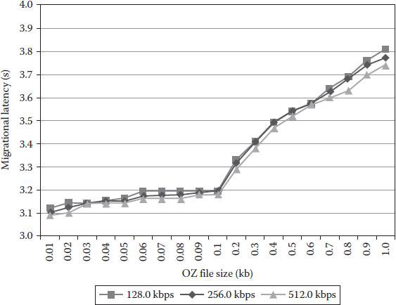
Figure 4.12 Migration latencies.
As Figure 4.12 illustrates, we conducted the experiment in network environments with a bandwidth of 128.0, 256.0, and 512.0 kbps. And we fed the OZ source file of the size in the range [0.01 kb, 1.0 kb] into which we thought common applications should fall. The result shows that network conditions today should not be a bottleneck for migration latencies and that the OZ file size (though minor) plays the main role in causing the latencies.
4.2.5.2 Prototype for Multimodalities
We built our second prototype to exhibit the ability of our platform to support multimodalities of applications. We equipped the migration-target workstation with the vocal device, and we pre-installed two well-written plug-ins. One is the standard input adapter through which the input from the keyboard/mouse will feed the application, and another is the vocal command adapter, which can be used to substitute for the standard input adapter after the migration to input command to the application. Those two adapters are successfully discovered and managed by IOAMM.
We triggered the migration and noticed that DDEM discovered the vocal device successfully and collaborated with IOAMM to substitute the original standard input adapter with the vocal adapter. We gave the voice command start in the microphone, and the truck started to race after recognizing the command. The command stop stopped the race successfully.
Computing Resource Management Systems and Methods
United States Patent Application 20100169893
http://www.freepatentsonline.com/y2010/0169893.html
Predictive Resource Management for Wearable Computing
D. Narayanan and M. Satyanarayanan. Predictive Resource Management for Wearable Computing, in Proceedings of the 1st international conference on Mobile systems, applications and services (MobiSys’03). ACM, New York, 2003, pp. 113–128.
XML Systems for Intelligent Management of Pervasive Computing Resources
D. Alexopoulos, G. Kormentzas, and J. Soldatos. XML Systems for Intelligent Management of Pervasive Computing Resources, in Artificial Intelligence Applications and Innovations: 3rd IFIP Conference on Artificial Intelligence Applications and Innovations (AIAI) 2006, I. Maglogiannis, K. Karpouzis, and M. Bramer, Eds. Boston, MA: Springer, 2006, pp. 245–253.
Lease-Based Resource Management in Smart Spaces
M. Jurmu, M. Perttunen, and J. Riekki. Lease-Based Resource Management in Smart Spaces, Fifth Annual IEEE International Conference on Pervasive Computing and Communications Workshops (PerComW’07), 2007, pp. 622–626.
A Context-Aware Learning, Prediction, and Mediation Framework for Resource Management in Smart Pervasive Environments
N. Roy, “A context-aware learning, prediction and mediation framework for resource management in smart pervasive environments,” Ph.D Thesis. Computer Science & Engineering, The University of Texas at Arlington, 2008.
Automatic Resource and Service Management for Ubiquitous Computing Environments
S. Maffioletti, M. S. Kouadri and B. Hirsbrunner. Automatic resource and service management for ubiquitous computing environments, Pervasive Computing and Communications Workshops, 2004. Proceedings of the Second IEEE Annual Conference on, 2004, pp. 219–223.
1. M. Satyanarayanan, Pervasive Computing: Vision and Challenges, IEEE Personal Communications, vol. 8, no. 4 pp. 10–17, 2001.
2. M. Kubo, B. Ye, A. Shinozaki, T. Nakatomi, M. Guo, UMP-Percomp: A Ubiquitous Multiprocessor Network-Based Pipeline Processing Framework for Pervasive Computing Environments, in Proceedings of the IEEE AINA’07.
3. A. Shinozaki, M. Shima, M. Guo, and J. Kubo. A High Performance Simulator System for a Multiprocessor System Based on Multi-Way Cluster, in Proceedings of 2006 Asia-Pacific Conference Computer System Architecture Systems, Shanghai, China, 2006, pp. 231–243.
4. L. Kleinrock, Queueing Systems Volume 2: Computer Applications, Wiley, 1979.
5. Queuing Theory Basics. Available from: http://www.eventhelix.com/RealtimeMantra/CongestionControl/queueingtheory.htm August 21, 2010.
6. Kendall’s Notation. Available from: https://en.wikipedia.org/wiki/Kendall%27s_notation last modified on September 23, 2015.
7. X.Org project: http://www.x.org/, accessed on October 21, 2010.
8. T. Richardson, Q. Stafford-Fraser, K. R. Wood, and A. Hopper. Virtual Network Computing. IEEE Internet Computing, vol. 2, no. 1, pp. 33–38, 1998.
9. Remote Desktop Protocol. Available from: http://msdn.microsoft.com/en-us/library/aa383015(VS.85).aspx, accessed on December 20, 2015.
10. Microsoft System Center Configuration Manager. Available from: http://www.microsoft.com/systemcenter/configurationmanager/en/us/default.aspx, accessed on August 21, 2010.
11. J. M. Smith. A Survey of Process Migration Mechanisms. Technical Report CUCS-324-88. Computer Science Department, Columbia University, New York, NY.
12. The Mozart Programming System. Available from: http://www.mozart-oz.org/, accessed on August 21, 2010.
13. S. Mitchell. Understanding ASP.NET Viewstate. Available from: http://msdn.microsoft.com/en-us/library/ms972976.aspx, accessed on December 20, 2015.
14. G. Smolkal. The OZ Programming Model. EURO-PAR’95 Parallel Processing, vol. 966, Berlin: Springer, 1995.
15. D. Grolaux, P. Van Roy, J. Vanderdonckt. QTk—A Mixed Declarative/Procedural Approach for Designing Executable User Interfaces, in 8th IFIP Working Conference on Engineering for Human-Computer Interaction (EHCI’01), 2001, pp. 109–110.
16. Tcl Programming Language & Tk Graphical User Interface Toolkit. Available from: http://www.tcl.tk/, accessed on August 21, 2010.