Transforming and Motion Tracking
There are many opportunities to apply animation inside a compositing program such as After Effects. That is, you’re not limited to the motion contained within imported renders or footage. You can animate the layer transforms, which include position, rotation, and scale. When transform animation is present, you can activate motion blur to mimic the way a real-world camera captures its images. You can also add motion by motion tracking. Motion tracking captures the movement of features within footage and applies that motion to nonmoving layers (Figure 4.1). This creates the illusion that the affected layers were shot with the original camera.
This chapter includes the following critical information:
• Overview of layer transformation, parenting, and nesting
• Applying motion tracking, including transform, corner-pin, and stabilization tracking
• Introduction to planar and 3D camera motion tracking
Each layer in After Effects receives a set of properties in the layer’s Transform section. These include Anchor Point, Position, Scale, Rotation, and Opacity.
By default, the Anchor Point value is set to the layer center and is indicated by a small crosshair icon in the view panel when the layer is selected (Figure 4.2). For example, a 1920 × 1080 layer has an Anchor Point value of 960, 540 and a 100 × 100 layer has an Anchor Point value of 50, 50. In contrast, the Position is set to the center of the composition. Thus, a layer that is 100 × 100 has a default position of 250, 250 in a 500 × 500 composition (Figure 4.2).
Keep in mind that After Effects screen space places 0, 0 at the top left of the frame. Thus, moving a layer to 0, 0 places the layer’s Anchor Point crosshair at the top left. As such, X runs left to right and Y runs from top to bottom.
Changing the Anchor Point value changes the pivot point of the layer. The pivot is the point from which and around which all transforms occur. Hence, changing the Rotation value causes the layer to spin around the current Anchor Point location. Altering the Anchor Point is often useful for offsetting motion-tracked animation, which is demonstrated later in this chapter.
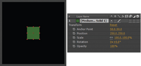
FIG 4.2 Left: A 100 × 100 solid layer in a 500 × 500 composition (the Anchor Point is indicated by the small crosshair at the layer center). Right: The corresponding Transform section of the layer.
Working with Additional Transform Properties
Here are a few tips for working with properties in the Transform section:
Dual Properties
Properties with two values always include the X value on the left and the Y value on the right. This follows the same logic as resolution where X (width) comes before Y (height).
Linked Scale
Scale is linked by default. To change the Scale X and Y values individually, click the link icon (see Figure 4.2) so it disappears. You can re-click the link icon at any time to relink the current X and Y values.
Rotation Revolutions
Rotation carries two numeric values: revolution and degrees. Each time degrees surpasses 360, the revolution value is increased by 1.0, and the degrees are reset to 0. However, when working with a Rotation curve in the Graph Editor, the total number of degrees is stored by keyframes. For example, if the Rotation property reads 2x90, the curve value is stored as 810, which is equal to (360 × 2) + 90.
Keyframing
You can keyframe any transform property. Each property carries a Time icon. To jump between keyframes, click the small forward and backward buttons to the left of the keyframed property.
By default, Position X and Position Y are linked and cannot be keyframed separately. At the same time X and Y cannot be edited separately in the Graph Editor. However, you can RMB-click over the Position name in the Transform section and choose Separate Dimensions from the menu. For a demonstration, see the previous chapter.
Resetting
You can return the transforms of a layer to their defaults by clicking the word Reset at the top of the Transform section.
For more specific techniques covering keyframing and working within the Graph Editor, see Chapter 3.
You can parent one layer to another by changing the Parent menu to the name of the parent layer (Figure 4.3). (If the Parent menu is not visible, click the Toggle Switches/Modes button at the bottom of the layer outline.) This forces the “child” layer to adopt the transforms of the parent. If both the child and parent layer possess unique transforms or transform animations, the net transformation values are used. For example, if the child layer is rotated 45 degrees and the parent layer is rotated 10 degrees, the net rotation for the child layer is 55 degrees. That said, the transforms passed to the child layer occur at or around the parent layer’s Anchor Point position and not the position of the child’s Anchor Point. Nevertheless, parenting offers a convenient means to have one layer “follow” another.
Nesting and Transform Collapsing
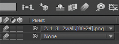
FIG 4.3 The Parent menu for two layers appears at the bottom right of this figure. With this example, the top layer is parented to the bottom layer. The Motion Blur switch sits to the left of the menus and is activated for both layers. However, the Enables Motion Blur switch for the composition (at the top center) has not yet been activated.
When creating a complex project in After Effects, you often wind up with a large number of layers in a single composition. A large stack of layers can make it difficult to fine-tune the result. One way to avoid this is to use additional compositions. In order to pass the result of one composition to the next, you can nest compositions. To nest one composition into a second composition (referred to as a containing composition), LMB-drag the composition from the Project panel and drop it into the second, containing composition on the timeline. When a composition is nested, it’s essentially flattened and appears as a single, new layer (Figure 4.4).
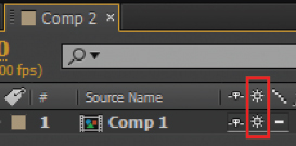
FIG 4.4 A nested composition, named Comp 1, is nested in Comp 2. Note the Collapse Transformations switch (outlined in red).
Nesting offers several advantages:
Transform and Effect Application You can apply transformations or effects to a nested composition in one step (as opposed to applying the transformations or effects to numerous layers).
Linked Compositions The original composition remains intact with all its layers, transforms, and effects. If you adjust the original composition, the nested version updates automatically.
Simplification Nesting allows you to create a series of compositions with fewer contained layers. This simplifies the management of complex projects and prevents a single composition from becoming crowded and difficult to see within the timeline area.
One potential danger of nesting comes in the form of redundant transformations that create a loss of quality. For example, the following scenario produces a degraded result:
• Layer 1 within Comp 1 is scaled by 50 percent.
• Comp 1 is nested within Comp 2.
• The Comp 1 layer within Comp 2 is scaled by 150 percent.
With this scenario, the net scale applied to Layer 1 is 75 percent (50 percent scale in Comp 1 and 150 percent scale in Comp 2). Because the scale transformation happens in two steps, the resulting pixels are blurrier. If a single transformation were applied (75 percent scale), the result would be sharper. The combination of transformations to preserve quality is called concatenation. With After Effects, concatenation is achieved with the Collapse Transformations switch, which each nested composition carries (see Figure 4.4).
If the Collapse Transformations switch is selected for a nested composition, the transformations are applied after the effects and masks are applied. This allows the transformations of the nested and containing composition to be combined. If you nest a vector layer, such as a shape or text, the Collapse Transformations switch is replaced with a Continuously Rasterize switch.
Precomposing and Pre-Rendering
As an alternative to manually nesting a composition within a second composition, you can precompose specific layers. Precomposing moves selected layers into a new composition; the new composition is then nested into the original composition. To precompose in After Effects, you can follow these steps:
1. Select the layer or layers you wish to precompose. Choose Layer > Pre-Compose through the main menu.
2. In the Pre-Compose window, enter a name for the new composition to be created. If you’ve selected more than one layer within the composition, the Move All Attributes Into New Composition is selected by default. Click the OK button to close the window. The new composition is created and the selected layers are placed within it. The layers are moved with their transforms, masks, and effects. The new composition is nested within the original composition.
3. If you’ve only selected one layer, you have the option to choose the Leave All Attributes In Comp option (Figure 4.5). With this option, the selected layer is placed within the new composition, but the transforms, masks, and effects are applied to the nested composition layer.
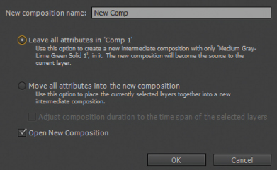
FIG 4.5 The Pre-Compose window with one layer selected.
In contrast, pre-rendering allows you to render out a movie or image sequence and thus permanently flatten a composition. To pre-render in After Effects, select a composition and choose Composition > Pre-Render. The Composition is added to the render queue. Set the Output Module and Output To options to select an appropriate render format and location and press the Render button. After the completion of the render, the rendered movie or image sequence is imported automatically. Any nested iteration of the rendered composition is replaced with the movie or the image sequence. Pre-rendering a complex composition can save a significant amount of rendering time as you continue to build the project. However, you should not pre-render until you feel a composition has been thoroughly adjusted and is complete or close to completion. When you choose the Pre-Render option, the Post-Render Action menu, in the Output Module Settings window, is set to Import & Replace Usage.
Any layer that carries transform animation, whether it’s through changes in position, rotation, or scale, can gain motion blur. Motion blur is a natural artifact of real-world cameras that require a small period of time to expose a single frame (referred to as shutter speed). For example, if the shutter speed is 1/30th of a second, the motion blur trail of a moving object corresponds to the distance the object moves in 1/30th of a second.
To activate the motion blur in After Effects, click the small Motion Blur switch beside the layer name (see Figure 4.3 earlier in this chapter). The switch carries three small circles. If the switch does not appear, click the Toggle Switches/Modes button at the bottom of the layer outline. In addition, you must activate motion blur for the entire composition by clicking Enables Motion Blur For All Layers at the top of the layer outline.
The length of the motion blur trail is determined by the distance the layer moves during one frame and the Shutter Angle and Shutter Phase property values. Shutter Angle and Shutter Phase are located in the Advanced tab of the Composition Settings window (Figure 4.6). (Each composition may carry unique Shutter Angle and Shutter Phase values.)
By default, Shutter Angle is set to 180 degrees, which emulates common video camera shutters. However, you can increase this value to lengthen the motion blur trail or reduce the value to shorten the motion blur trail. You can determine the virtual shutter speed (as measured in After Effects frames), and the length of the corresponding motion blur trail, with the following formula:
Shutter Speed = 1/(360/Shutter Angle)
Thus, to create a blur trail equivalent to a shutter speed that lasts 1 frame, set Shutter Angle to 360 degrees. In contrast, Shutter Phase determines when, in time, the motion blur trail starts and ends. You can use the following formula to determine the blur start and end frames, which remain dependent on the Shutter Angle:
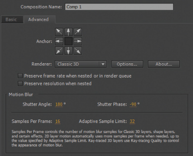
FIG 4.6 The Advanced tab of the Composition Settings window.
Start Frame = Current Frame − (1/(360 / (Shutter Angle + Shutter Phase)))
End Frame = Current Frame + (1/(360 / (Shutter Angle + Shutter Phase)))
Thus, if Shutter Angle is 180, Shutter Phase is −90, and the current frame is 2, the motion blur start frame is 1.75 and the motion blur end frame is 2.25. To center the motion blur trail at the layer’s current position (so the trail extends backwards and forwards in time), set the Shutter Phase value to (Shutter Angle/2) * −1. The ability to adjust the start and stop of motion blur trails, as well as the motion blur trail length, is useful for matching After Effects blur to the motion blur contained within live-action film or video footage.
The Advanced tab of the Composition Settings window also includes quality settings in the form of Samples Per Frame and Adaptive Sample Limit. The higher the Samples Per Frame and Adaptive Sample Limit, the smoother the resulting blur but the longer the render time. Standard 2D layers use sample values between the Samples Per Frames and Adaptive Sample Limit, depending on the aggressiveness of the blur. (3D layer rendering is discussed in Chapter 5.)
Motion tracking is a process through which the motion of a feature within a piece of footage is determined. You can apply the motion-tracking data to a different layer and thereby have the layer pick up the same motion. In general, the main goal of motion tracking is one of the following:
• To impart motion to a different layer so that it looks like the layer was shot with the same real-world camera. The layer may take the form of a 3D render, a static piece of artwork, or video footage. For example, if you shoot a television with a moving camera, you can use motion tracking to place new video footage onto the television screen. This type of motion tracking is commonly known as matchmoving. (Matchmoving is sometimes used to refer to all forms of motion tracking.)
• To impart motion to a different layer so that the layer appears to follow a particular feature. The camera need not move in this case. For example, you can use motion tracking to add a 3D object to the hand of a person who is gesticulating.
• To remove motion. You can use motion tracking to remove camera jitter or minor movement so that it appears as if the camera is static. This process is known as stabilization.
Transform tracking is a variant of motion tracking where the motion is only detected in the X and Y directions. Transform tracking can detect changes in position, rotation, and scale (scale changes may occur as a camera “zooms” in or out or an object moves closer or farther from the camera). After Effects supports transform tracking through the Track Motion tool. The Track Motion tool allows you to select a particular feature within the frame. A feature is a set of identifiable pixels. A feature might be a motion-tracking tape mark, the corner of a poster, a pebble on the ground, a rivet on a machine, a sticker, or any other small pattern. To apply the Track Motion tool, use the following tutorial as a guide.
Track motion mini-tutorial
With this tutorial, we’ll detect the motion within a shot and apply the motion-tracking data to a null object as a test. Follow these steps:
1. Create a new After Effects project. Import 1_31_2wall.##.png from the ProjectFilesPlatesMotionTracking1_3i_2wall directory. Set the frame rate interpretation to 24 fps. LMB-drag the image sequence into a new composition.
2. Choose Layer > New > Null Object. A Null 1 layer is added to the composition. Null objects do not render, but carry a set of transforms. You can apply motion-tracking data to a null as a test.
3. With the footage layer selected, choose Animation > Track Motion. The Layer view opens. The Tracker panel also opens at the bottom right of the program (Figure 4.7). Note that the Position radio checkbox is selected by default.
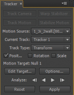
FIG 4.7 The Tracker panel.
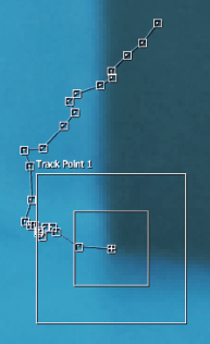
4. A track point, Track Point 1, is displayed in the Layer view. LMB-drag the track point (place the mouse over an empty space within the nested point boxes) and place it over a corner where horizontal and vertical tape marks meet (Figure 4.8). When you LMB-drag the track point, a zoomed-in view of the pixels within its feature region (the center box) is displayed.
5. In the Tracker panel, press the Analyze Forward button. The timeline is played forward and the motion of the feature within the Anchor Point feature region (the inner box) is detected. A motion path is laid down in the viewer to indicate this motion (see Figure 4.1 at the start of this chapter).
6. When the timeline reaches the final frame, click the Tracker panel’s Edit Target button. In the Motion Target window, change the Layer menu to Null 1. Click the Tracker panel’s Apply button. Press the OK button when the Motion Tracker Apply Options window opens. The view panel switches back to the Composition view. The Null 1 layer’s Position is keyframed automatically to follow the tracked feature.
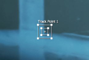
FIG 4.8 Track Point 1 is positioned over a corner formed by tape marks on the wall.
7. Manually scrub the timeline by LMB-dragging the Current Frame Indicator bar in the timeline. The red square of the null follows the tape corner as if it was shot by the same real-world camera (Figure 4.9). Note that the null’s upper-left corner is pinned to the motion path.
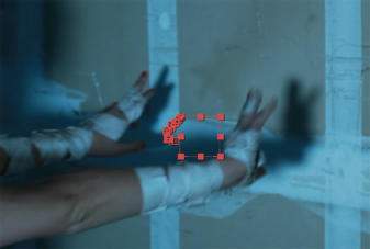
FIG 4.9 Motion-tracking data is applied to a null object, which appears as a red box when the null layer is selected. The null layer’s animated Position property creates a red motion path in the view panel.
Although this tutorial uses footage with easy-to-track motion, other shots may be more difficult. Hence, there are numerous ways to adjust track points, add additional track points, and manipulate the resulting motion paths. These techniques are discussed through the remainder of this chapter. A completed version of this tutorial is saved as mini_transform_tracking.aep in the ProjectFilesaeFilesChapter4 directory.
Selecting Features and Fine-Tuning Motion Paths
When choosing a feature to track, look for the following traits:
Small Pattern Although you can increase the size of the track point region boxes, large regions slow the motion-tracking calculation.
High-Contrast Features that include high-contrast edges produce the best tracking results.
Low Motion Blur The heavier the blur, the more difficult it is to accurately track a feature over time.
No Occlusion Features that enter or exit the frame or are covered by other objects will cause the motion tracker to fail.
Stable Lighting Features that enter or exit light fields or shadows are more difficult to track due to the change in color values.
It may not be possible to find a feature that fulfills all the listed criteria. As such, you may need to fine-tune the resulting motion paths. There are various ways to do this, which are discussed here.
Reanalyze
You can write over previously tracked motion paths by reanalyzing. You are free to analyze forward or backward. You can also analyze in both directions one frame at a time. Hence, Analyze Forward, Analyze Backward, Analyze 1 Frame Forward, and Analyze 1 Frame Backward buttons are included in the Tracker panel.
Choose a New Feature
If a feature produces an inaccurate motion path or causes the tracker to consistently fail, choose a new feature and reanalyze. Note that you should set the Composition panel’s Resolution/Down Sample Factor menu to Full—otherwise, the Layer view will display a simplified version of the frame (where pixels are skipped) and it will be more difficult to accurately track features.
Analyze from a Mid-Point
You are not obligated to track from frame 0 or frame 1 forward. You can position the track point on any frame where the feature is easily seen. You can then analyze forward and/or analyze backward. The order of analysis is up to you.
Adjust the Anchor Point Regions
At any phase of the tracking process, you are free to adjust the Anchor Point regions. To do so, LMB-drag a box corner point. The inner region, indicated by the inner box, is the feature region. The feature region defines the pattern of pixels that is tracked. The outer region, indicated by the outer box, is the search region, and defines the area in which the program searches for the feature should the feature be temporarily lost due to occlusion, rapid motion, change in lighting, and so on.
A keyframe is laid down for each frame of the timeline that is tracked. The keyframes appear on the motion path in the Layer view as hollow boxes. You can LMB-drag the keyframe boxes to new positions. This is particularly useful if the motion path suddenly moves off the feature. Use manual adjustment sparingly, however, as it can lead to jitter.
Track a Different Channel
If you click the Options button in the Tracker panel, the Motion Tracker Options window opens (Figure 4.10). Here, you can choose to track a particular channel through the Channel section. The Luminance option compares pixel brightness and is suitable for high-contrast footage. The RGB option compares red, green, and blue pixel values and ignores brightness; this is useful for footage that carries distinct colors, such as green screen footage. The Saturation option examines its namesake, which is the amount of contrast that exists between color channels.
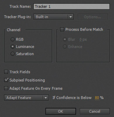
FIG 4.10 The Motion Tracker Options window, as seen in CC 2014.
In the Motion Tracker Options window, you can select the Process Before Match checkbox. You then can choose Blur or Enhance. Enhance sharpens the footage before the motion tracking is applied. This is useful for soft or blurry footage. Blur applies a blur filter with a strength set by the accompanying field. Blur can improve the tracking results for footage that carries heavy film grain or video noise. Note that After Effects CC 2015 removes the Process Before Match section. Instead, CC 2015 offers an Enhance Before Match checkbox. Nevertheless, you can apply your own pre-process by applying effects to a footage layer, nesting the layer’s composition into a second composition, and then applying Track Motion to the nested composition in the containing composition.
Alter the Tracker Behavior
In the Motion Tracker Options window, you can choose what the tracker does when its confidence drops. Confidence is the mathematical certainty with which the tracker has found the correct feature pattern for a frame. With the behavior menu set to Adapt Feature, the tracker allows for variations in the feature pattern over time. Although the tracker is less likely to fail with this setting, it may cause the track point to suddenly “jump” to a feature pattern that is roughly equivalent to the original. Despite this, Adapt Feature generally produces good results with a wide range of footage. Nevertheless, you can set the behavior menu to Continue Tracking, which ignores a loss in confidence and presses ahead, or Extrapolate Motion, which estimates the position of the feature by deleting low-confidence keyframes (hence, some positions are inbetweened). You can also set the menu to Stop Tracking, which simply kills the tracking when the confidence reaches a value below the percentage set by the If Confidence Is Below field. It may be useful to raise the percentage value when working with difficult footage to prevent the tracker from dying on each and every frame.
Transform Tracking with Rotation and Scale
By default, the Track Motion tool only detects positional changes. However, you can choose to track rotation and/or scale changes. To do so, select the Rotation and Scale checkboxes in the Tracker panel before analyzing. The addition of the Rotation or Scale dimensions adds a second track point, Track Point 2, to the Layer view. The two track points are connected by a “rubber band” and are needed to determine if the camera or particular objects undergo rotation, become larger, or become smaller (Figure 4.11).
You can position and scale Track Point 2 as you would place Track Point 1. For example, if you want to detect the rotation and zoom of a handheld camera, place the two track points along the edge of a door or window or similar straight edge. Optimally, the pixel pattern below each point’s feature region should possess the traits listed in the prior section. When you apply the motion-tracking data with Rotation and Scale selected, the target layer’s Position, Scale, and Rotation properties are keyframed automatically.
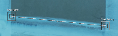
FIG 4.11 The addition of Rotation to the tracker creates Track Point 2. Here, the track points are lined up along a tape edge. Each track point is centered over a high-contrast corner.
Adjusting Applied Tracking Transforms
As discussed, applying the motion-tracking data creates keyframes for the Position, Rotation, and/or Scale properties of the target layer. Although you can alter the resulting animation curves in the Graph Editor, this becomes difficult due to the large number of keyframes. Alternatively, you can use the techniques in this section to refine the animation.
Adjusting the Anchor Point
If the target layer suddenly “jumps” to an undesirable location when the motion-tracking data is applied, you can correct its position by altering its Anchor Point values. This adjustment does not harm the motion-tracking data and does not alter the Position animation. When you apply motion-tracking data, the Anchor Point of the target layer is lined up with the attach point of Track Point 1 (which is indicated by a small + icon at the track point’s center).
Deleting Keyframes
You can delete Position, Scale, and Rotation keyframes to make the corresponding curves easier to work with in the Graph Editor. You can also decimate a curve by using the Smoother tool (Figure 4.12). To apply the Smoother, choose Window > Smoother, select keyframes of a curve in the Graph Editor or timeline view, and press the Apply button in the Smoother panel (the panel appears at the bottom right of the program). You can increase the aggressiveness of the decimation by raising the Tolerance value in the Smoother panel.
Updating the Motion Paths
At any time, you can return to the Tracker panel and refine the motion-tracking motion paths. You can reapply the data and thus overwrite the old transform animation of the target layer.
If the Tracker panel is closed, choose Window > Tracker. If a prior tracking session is not visible in the Tracker panel, change the Motion Source menu to the layer to which Track Motion was applied. Note that each time you choose Animation > Track Motion, a new tracker is created and named Tracker n. You can choose to work with a specific tracker by changing the Current Track menu to the tracker name. Each tracker is listed in the Motion Trackers section of the layer (above the Transform section). Keyframes for the track point position (named Feature Center), track point attach point position (same as Feature Center unless manually moved), and confidence value are stored in this section.
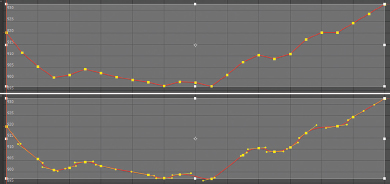
FIG 4.12 Position X curve created by motion tracking. The top view shows the curve before decimation, with one keyframe per frame. The bottom view shows the curve after the decimation provided by the Smoother tool with a Tolerance value of 0.5.
Occasionally, it may be necessary to motion track multiple features. This is generally required when no single feature is clearly visible throughout the entire duration of the composition. For example, features may enter or leave the frame, become occluded, or suffer from heavy motion blur. You can follow these basic steps to track multiple features:
1. Determine what feature is available at the start of the footage. Place the track point over the feature. Analyze Forward until the feature is no longer viable. You can stop the analysis by pressing the Stop button in the Tracker panel.
2. Locate a new feature that is visible from that point forward. If the last few frames of previous tracking are inaccurate, back up to an earlier frame by LMB-dragging the Current Time Indicator bar.
3. Alt/Opt + LMB-drag the track point to the new feature. If you use Alt/Opt while dragging, the track point attach point remains along the original motion path. Analyze forward. Repeat steps 2 and 3 if you need to jump to additional new features.
4. After you’ve analyzed the entire timeline, apply the data by clicking the Apply button. After Effects takes into account the multiple features with their offset motion path segments and applies a single, continuous keyframe animation to the target layer. The target layer’s Anchor Point is lined up with the Track Point 1 attach point, which remains along the motion path created for the first feature that was tracked.
You can use the Track Motion tool to stabilize a plate and thus make it appear as if the camera is not moving. To practice stabilization techniques, use the following tutorial.
Stabilization mini-tutorial
1. Create a new After Effects project. Import shake.##.png from the ProjectFilesPlatesMotionTrackingShake directory. Set the frame rate interpretation to 24 fps. LMB-drag the image sequence into the timeline to create a new composition. Play back the timeline. Note that the shot features two types of camera motion: smooth tilts and high-frequency jitter.
2. With the new layer selected, choose Animation > Track Motion. The Layer view opens. The Tracker panel also opens at the bottom right. Change the Track Type from Transform to Stabilize.
3. A track point, Track Point 1, is displayed in the Layer view. While on the first frame of the timeline, LMB-drag the track point and place it at the corner of the left-hand tracking tape mark. Place the Anchor Point’s attach point over at the border between the white tape and the green screen. Scale the feature region and search region boxes so that they cover most of the tape X (Figure 4.13).
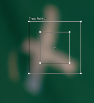
FIG 4.13 Track Point 1 is placed and scaled over the left-hand tracking mark.
4. In the Tracker panel, press the Analyze Forward button. The timeline plays forward and the motion of the feature within the Anchor Point feature region (the inner box) is detected. A motion path is laid down in the viewer to indicate this motion.
5. When the timeline reaches the final frame, click the Tracker panel’s Apply button. The motion-tracking data is applied to the same layer. The view panel switches to the Composition view. The layer’s Anchor Point is keyframed automatically.
6. Play back. The layer is moved left/right and up/down in order to pin the position of the tracking tape mark so it does not move. Thus, in turn, the camera appears static.
7. The stabilization reveals the frame edges as the frame is repositioned (Figure 4.14). This leads to black gaps at the bottom and right sides. To avoid this, create a new composition with the same resolution, frame rate, and duration, and nest the first composition into it. Go to the nested layer and change the Scale to 110 percent and the Position Y value to 567. Play back. The gaps are no longer visible.
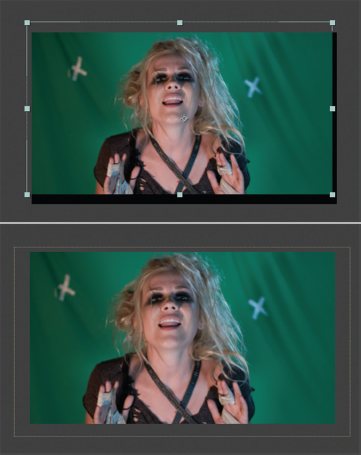
FIG 4.14 Top: The stabilization of the layer reveals the layer edges and black gaps at the edge of the composition. Bottom: The composition is nested and scaled, removing the gaps.
Note that stabilization is unable to remove motion blur created by the moving camera. A completed version of this tutorial is saved as mini_stabilization.aep in the ProjectFilesaeFilesChapter4 directory.
Corner-pin tracking utilizes four track points to follow a rectangular feature. For example, you can use corner-pin tracking to track the four corners of a window, door, picture frame, cell phone screen, billboard, and so on. When you apply corner-pin motion-tracking data to a layer, the four corners of the layer are moved to the track point positions, thus fitting the layer to the tracked rectangle. To apply corner-pin tracking, you can use the following tutorial.
Corner-pin mini-tutorial
You can use the Track Motion tool to apply corner-pin tracking. To practice this form of tracking, follow these steps:
1. Create a new After Effects project. Import wallpov.##.png from the ProjectFilesPlatesMotionTrackingWallPOV directory. Set the frame rate interpretation to 24 fps. LMB-drag the image sequence into the timeline to create a new composition.
2. With the wallpov.##.png footage layer selected, choose Animation > Track Motion. The Layer view opens. The Tracker panel also opens at the bottom right.
3. Change the Track Type menu from Transform to Perspective Corner Pin. Four track points, connected by “rubber bands,” are added. Play back the timeline to determine which frame contains a minimal amount of camera motion blur. For example, frame 10 is relatively sharp.
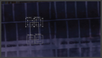
FIG 4.15 Positioned and scaled track points.
4. Position the track points over the four corners formed by overlapping paint lines (Figure 4.15). Select corners that contain good contrast. You can move each point independent of the other. Note that the track points are numbered in the following fashion (starting at the top left and moving clockwise): 1, 2, 4, 3. It’s best to maintain that order. Moving the track points past each other so that the bands become twisted and the track point order changes may cause tracking errors. Feel free to adjust the feature and search region boxes of the track points. Larger boxes will improve the tracking when the footage is dimly lit or otherwise low contrast.
5. Use the Analyze buttons to create motion paths for the track points. Use the suggestions in the “Selecting Features and Fine-Tuning Motion Paths” section earlier in this chapter to maximize the quality of the motion paths. Note that the relatively dim lighting and heavy camera blur contained within the first few frames makes the motion tracking particularly difficult in that area. Hence, it may be necessary to manually place the track points in the correct locations for those few frames.
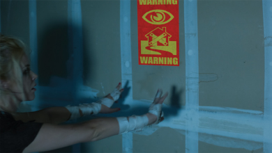
6. When the motion paths are complete, import the warning.png file from the ProjectFilesArt directory. LMB-drag the warning image to the top of the layer outline. Click the Edit Target Button in the Tracker panel and check that the drawing layer is selected. Click the Apply button. The view panel returns to the Composition view. A Corner Pin effect is added to the warning layer and appears in the Effects section. The effect carries four sets of keyframes that determine the new positions of the layer’s corners. Thus, the layer is distorted to fit the tracked rectangular shape. Play back the timeline. The four layer corners are placed at the attach point positions of the track points. In addition, the warning layer’s Position property is animated.
FIG 4.16 The warning sign layer is distorted to fit the tracked rectangle. Motion blur is activated. The drawing layer’s Opacity is reduced to 50 percent.
7. Although the sign layer now carries transform animation, there is no motion blur. Activate the blur by clicking the layer’s Motion Blur switch. Make sure that the composition’s Enables Motion Blur For All Layers switch is also activated. Play back. The sign gains heavy motion blur that matches the footage. Feel free to adjust the motion blur settings in the Advanced tab of the Composition Settings window (see the “Motion Blur” section earlier in this chapter). To better integrate the sign, reduce the warning layer’s Opacity to 50 percent. This allows the purple of the wall to mix with the paper colors (Figure 4.16). A finished version of this tutorial is saved as mini_corner_pin.aep from the ProjectFilesaeFilesChapter4 directory. (To better integrate the sign, we’ll also apply color-grading techniques in Chapter 9.)
If the distortion of the targeted layer prevents the layer from retaining a rectangular or square shape, you can offset the corner pin animation and “push” the corners back into a more desirable location. To make the warning sign wider and a bit more rectangular, you can follow these additional optional steps:
1. Expand the Corner Pin section of the warning layer. Select one of the corner names, such as Upper Left. Open the Graph Editor. LMB-drag a selection marquee around all the keyframes of either the X (red) or Y (green) curve. Place your mouse over one of the selected keyframes and LMB-drag straight up or straight down. The values of the keyframes are increased if you drag up or decreased if you drag down. The corner of the layer is moved in the viewer. Be careful not to drag the keyframes left or right in the Graph Editor, which offsets the animation curve in time.
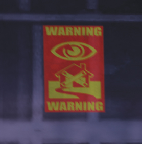
FIG 4.17 The sign is widened and made more rectangular and by offsetting the Corner Pin effect’s corner animation curves.
2. Repeat this process with other curves and other corners until the layer appears rectangular once again. You can also alter the scale of the layer by offsetting the corners (Figure 4.17). This does not affect the quality of the motion tracking. However, the farther you push the corners, the most potential there is to see subtle flaws in the tracking in the form of sliding. That said, you can adjust individual corner pin X or Y keyframes to smooth out the result. An offset version of this tutorial is saved as corner_pin_offset.aep from the ProjectFilesaeFilesChapter4 directory.
Note that the Track Type menu of the Tracker panel also provides the Parallel Corner Pin option. This is similar to Perspective Corner Pin but makes the Track Point 4 position dependent on the other three points. For example, if you move Track Point 2, Track Point 4 follows at the same distance. This form of corner pin is suitable for rectangular shapes that undergo predictable or subtle perspective changes.
3D camera tracking separates itself from 2D tracking methods, such as transform tracking, by operating in a 3D space. The goal of 3D camera tracking systems is the creation of a virtual camera within a 3D space that emulates the original real-world camera. 3D camera tracking attempts to match the real-world lens and any camera motion, such as tilts, pans, and dollies. Hence, 3D tracking is suitable for complex shots where the camera moves in multiple directions (as opposed to a camera that’s locked to a tripod).
A basic introduction to 3D camera tracking is included in the following two tutorials. After Effects provides the Track Camera tool for this task. In addition, The Foundry provides its own plug-in. (Note that the program’s 3D environment is discussed in great detail in Chapter 5.)
3D camera tracking mini-tutorial
In After Effects, you can use the Track Camera tool to apply 3D camera tracking. You can follow these basic steps:
1. Create a new After Effects project. Import 1_3b_4stand.##.png from the ProjectFilesPlatesMotionTracking1_3b_4stand directory. Set the frame rate interpretation to 24 fps. LMB-drag the image sequence into the timeline to create a new composition.
2. With the footage layer selected, choose Animation > Track Camera. A 3D Camera Tracker effects is added to the layer. A blue “Analyzing” bar appears over the frame in the Composition view. Stop the analysis by clicking the Cancel button at the top of the 3D Camera Tracker section in the Effect Controls panel (Figure 4.18).
3. Note that the Shot Type menu is set to Fixed Angle Of View. This setting is suitable if the camera used a fixed (nonzoom) lens, but the exact lens field of view is not known. If you are aware of the camera field of view, you can switch this menu to Specify Angle Of View and change the Horizontal Angle Of View slider to the correct value. A field-of-view value is derived through a trigonometric calculation involving the lens focal length and the physical size of the film aperture or image sensor:
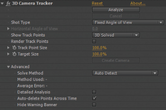
FIG 4.18 The 3D Camera Tracker effect with default values.
2 * arctan ((film frame or image sensor width/2)/focal length)
If the camera uses a zoom lens, where the focal length changes during the shot, set the menu to Variable Zoom. With this tutorial, the default Fixed Angle Of View option is appropriate.
4. Go to the Advanced section. Note that the Solve Method menu is set to Auto Detect. This forces the effect to determine the style of camera motion. The Solve Method menu offers three additional camera motion types: Typical, Mostly Flat Scene, and Tripod Pan. Tripod Pan assumes the camera is fixed but pans or tilts. Mostly Flat Scene allows for camera motion forwards, backwards, or sideways, but assumes the motion is limited to a single plane. Typical is appropriate for more aggressive camera moment such as a handheld camera that moves forward. For this tutorial, leave the menu set to Auto Detect.
5. Click the Analyze button. The blue bar changes back to “Analyzing.” The footage is analyzed in two passes (playing forward and playing backward). Upon the completion of the analysis, a number of track points are displayed in the viewer (Figure 4.19). These are points that are identified as specific positions in 3D space. Play back. A few points disappear as their associated feature disappears. A few may slide incorrectly. Others remain fixed to features throughout the duration of the timeline. The ones that stay fixed should be considered successful. The effect is able to determine the relative positions of the features in 3D space through parallax calculations. To view the points in perspective, the effect “solves” a virtual 3D camera and looks though it. During the analysis, the effect automatically identifies features that contain high-contrast, trackable patterns.
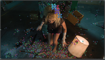
FIG 4.19 Track points displayed after analysis. Larger points represent features that are closer to the real-world camera. The large points on the head of the actress disappear as she moves and are not useful for motion tracking. Track Point Size is set to 150 percent.
6. If the track points are difficult to see, you can scale them by raising the Track Point Size value. If necessary, you can enter a large value into the Track Point Size field. (Track points are only visible if the effect is selected in the Effect Controls panel.) Track points that follow features close to the camera appear larger than those that follow features far from the camera (hence, this is one way to determine if the tracking is accurate). You are free to delete inaccurate or unneeded track points. To do so, LMB-click a track point center in the viewer, so that the track point is given a yellow circle, and press the Delete key. (Be careful not to delete the entire effect.) For example, consider deleting track points that appear over features on the body or clothing of the actress.
7. LMB-drag the mouse between track points. Note that a gray triangle and a red and black bullseye appears between sets of three. This indicates a plane in 3D space where the three track points intersect. You can use this knowledge to place a 2D layer on the identified plane. On the first frame of the timeline, drag your mouse between the points along the floor at the bottom left of frame. Due to the density of the points, the bullseye sometimes appears with incorrect rotation. As an alternative, you can manually select three or more points. To do so, Shift+LMB-click the point centers. Manually selecting points allows you to choose points that are further apart and more appropriate for representing the ground plane orientation (Figure 4.20).
8. With points selected, RMB-click over the bullseye and choose Create Text And Camera. This creates a 3D camera, which appears as a new layer. The transforms of the camera are animated to replicate the real-world camera. In addition, a text layer is created and converted to a 3D layer (the 3D Layer switch is on). The default text, Text, appears at the bullseye center and takes on the orientation of the bullseye. To hide the track points, simply deselect the 3D Camera Tracker effect.
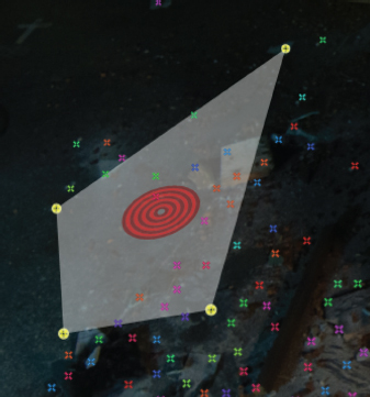
FIG 4.20 Four track points are manually selected. The resulting gray shape and bullseye represents the orientation of the floor.
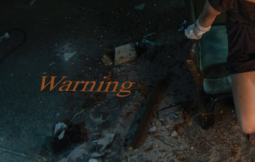
FIG 4.21 A text layer, converted to a 3D layer by the 3D Camera Tracker effect, is automatically positioned so that it appears to lie on the floor. A 3D camera, created and animated by the 3D Camera Tracker effect, creates the appropriate depth and perspective.
9. Play back the timeline. The text appears to lie on the floor as if it was shot with the original camera (Figure 4.21). Optionally, you can alter any of the text options for the text layer (through the Window > Character panel). For example, with this tutorial, the text appears very small; change the text Font Size field to 1200. You can also activate motion blur for the text layer, as well as offset the text by altering its transforms. As a 3D layer, the text has X, Y, and Z (depth) transform values.
Optionally, you can return to the 3D Camera Tracker and reanalyze with different settings. If you reanalyze, you have the additional option to create a brand new camera by clicking the Create Camera button. You are not limited to placing text in the scene. When you select three or more track points, you have the option to create a solid layer or a null object through the RMB menu. You can drive a custom 3D layer if you parent it to the null layer or link the transforms through expressions. More complex uses of 3D layers and 3D cameras are explored in Chapter 5. Expressions are covered in Chapter 10. A finished version of this tutorial is saved as mini_3d_camera.aep in the ProjectFilesaeFilesChapter4 directory.
Introduction to The Foundry’s CameraTracker
The Foundry offers the CameraTracker plug-in for After Effects to undertake the task of 3D camera tracking. Although the logic is similar to the After Effects Track Camera tool, the plug-in offers additional features. An overview of the plug-in is included in this section.
CameraTracker breaks the tracking process into three main steps. Each step is given a button with the step name and a section of options you can adjust before applying the step (Figure 4.22).
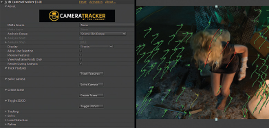
FIG 4.22 Left: CameraTracker properties. Right: Portion of solved tracking points and their partial motion paths.
The steps are designed for application in the following order:
1. Track Features This step identifies track points and tracks forwards and backwards across the entire timeline. When the tracking is complete, each track point is drawn in the viewer with a small x with a partial motion path trail. You can set the number of desired track points in the scene and adjust tracking sensitivity in the Tracking section before applying Track Features. You can choose one of two camera styles through the Track Validation menu: Free Camera, which is suitable for handheld shots, and Rotating Camera, which is suitable for tripod-based tilting and panning.
2. Solve Camera This step “solves” or creates an internal, virtual camera based on the tracking point data. When the camera is solved, the tracking points are color-coded (Figure 4.22). Green points are valid for the solution. Red points are unsuitable and generally represent points that disappear over time. The Solve section contains additional camera options. Here, you can set the Focal Length Type and Film Back Size before solving. If you know the real-word camera focal length, you can Set Focal Length Type to Known, set Units to mm, and choose the correct Focal Length size. (A camera’s film back represents the physical size of the camera sensor or exposed film frame.)
3. Create Scene This step creates a 3D camera layer that matches the solved camera. In addition, a null object is created as a 3D layer. The camera layer is parented to the null layer. Hence, the camera’s animated transforms are relative to the null layer, which is placed at the frame center.
In addition, the plug-in provides a Toggle 2D/3D button. Pressing this button switches to a view of the internal 3D space. The tracking appears as a cloud of dots. Looking at the 3D view is useful for determining if the track points are correctly oriented to a particular feature, such as the ground. (You can use the Unified Camera tool to alter the view to examine the points.) In fact, you can select points and define which axis or axes they belong to. For example, return to the 2D view by clicking the Toggle 2D/3D button again, draw a selection marquee box in the viewer over a group of points along the floor at the left of frame, and use the CameraTracker menu (embedded into lower left of the Composition view when the effect is selected) to choose Ground Plane > Set To Selected. The entire point cloud is reoriented in 3D space to align the selected points with the XZ plane. The camera position is also updated to keep the points aligned with the tracked features.
After the scene is created, you have the option to attach a new null object or solid layer to a track point. To do so, select a track point in the viewer and choose CameraTracker menu > Create > Null Object or CameraTracker menu > Create > Solid. The new null or solid layer is parented to the initial null layer and is given transform values that align them with the selected track point. You can drive a custom 3D layer if you parent it to the new null layer or link the transforms through expressions. More complex uses of 3D layers and 3D cameras are explored in Chapter 5. See The Foundry’s “CameraTracker” PDF user guide for more specific details on the plug-in (www.thefoundry.co.uk).
Occasionally, you may find that a particular shot is untrackable with the motion-tracking effects and plug-ins available to After Effects. This may be due to aggressive camera movement that prevents location of a usable feature. Extremely heavy motion blur, film grain, or video noise may also prevent the motion-tracking tools from producing usable motion paths. In this situation, you can apply hand tracking. Hand tracking uses these basic steps:
1. A mock-up of the real-world set or location is created as simple geometry in a 3D program, such as Autodesk Maya.
2. An image plane containing the footage is attached to the 3D camera.
3. The camera is animated to match the real-world camera motion. Lining up the geometry to the features within the footage aids in the positioning of the camera. For example, matching the edges of a building to a 3D mock-up of the building helps determine where the camera should be positioned and how it should be rotated.
4. The element that needs to be tracked, such as a 3D prop, is placed in the 3D scene and rendered with a 3D camera. The render is then composited on top of the original footage in After Effects or a similar compositing program.
With this scenario, the motion tracking actually occurs in the 3D program and not the compositing program. This is most likely to occur when a 3D object needs to gain the real-world camera motion. To maximize the quality of the hand tracking, it’s necessary to build the mock-up geometry as accurately as possible. Hence, real-world measurements and similar notes are useful. At the same time, real-world camera information is extremely valuable, such as the millimeter size of the lens, image sensor size, distance from the ground to the lens, and so on.
You can also hand track with After Effects. For example, it you need to track a label so that it follows an object in an actor’s hand, you can manually keyframe the label layer’s Position, Scale, and Rotation.
Motion Tracking Masks and Facial Tracking
The rotoscoping process can be time consuming due to the manipulation of the mask shape at numerous points across the timeline. You can simplify the rotoscoping, however, by using the Track Mask motion tracking option. To apply this option, you can follow these steps:
1. Create a mask over the feature you wish to isolate. The mask need not follow the feature tightly, but can loosely surround the feature. For example, you might draw a mask around a desired element, such as a face, or unwanted elements, such as motion tracking marks (in which case, you can invert the mask to remove the features).
2. RMB-click over the mask name in the layer outline and choose Track Mask. The Tracker panel opens with a set of Analyze playback buttons and a Method menu.
3. Set the Method menu to the style of motion tracking you prefer. If the feature is moving left/right or up/down with no rotation or scale change, set Method to Position. If the feature is rotating and changing size, set Method to Position, Scale & Rotation. If the feature goes through changes in perspective, set Method to Perspective.
4. Use the Analyze buttons to analyze the timeline. When the analyzation is complete, the Mask Path property is automatically keyframed. Play back the timeline. The mask follows the feature.
After Effects CC 2015 includes two facial tracking options: Face Tracking (Outline Only) and Face Tracking (Detailed Features). These options are available through the Method menu of the Tracker panel when the Track Mask option is chosen. To apply facial tracking, follow these steps:
1. Create a mask over the face you wish to motion track. Draw the mask loosely around the face.
2. RMB-click over the mask name in the layer outline and choose Track Mask. The Tracker panel opens with a set of Analyze playback buttons and a Method menu. Set Method to Face Tracking (Outline Only) or Face Tracking (Detailed Features).
3. Use the Analyze buttons to analyze the timeline. If Method is set to Outline Only, the Mask Path property is automatically keyframed. Play back the timeline. The mask follows the edges of the visible face. If Method is set to Detailed Features, the mask is animated and a Face Track Points section is created and added to the Effects section of the layer (Figure 4.23).
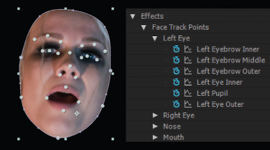
FIG 4.23 Left: A face is automatically masked with the Face Tracking (Detailed Features) motion tracking option. In addition, face track points follow important facial details over time. Right: A portion of the resulting Face Track Points section in the layer outline. An example project is saved as facial_tracking.aep in the ProjectFilesaeFilesChapter4 directory.
The Face Track Points section includes many properties that plot the X and Y positions of various facial details, including the upper and lower eyelids, corners of the nose, corners of the mouth, and upper and lower lips. You can copy the keyframe animation of any Facial Track Point property and paste it onto a different layer. In this way, you can force a different layer to follow a particular facial detail over time. You can also use the Facial Track Points properties as part of an expression. (Expressions are discussed in Chapter 10.) The track points appear in the Composition view as circles with crosshairs but will not appear as part of the final render.
Planar tracking is a motion-tracking variation that tracks the location and rotation of a planar shape. Although superficially similar to corner-pin tracking, planar tracking is aware of the planar shape as a whole and is able to follow a shape whose corners may be temporary occluded and briefly leave the frame. Although you can use planar tracking to follow a rectangular shape, you can use it to track any shape that exists within a single two-dimensional plane (in other words, any shape that is essentially flat in the real world). You can use planar tracking to track a wall, the side of a box, a lined parking space, an irregular wooden cutout, a gear ringed with teeth, and so on. The following tutorial takes you through the basic steps of planar motion tracking.
Chapter Tutorial: Planar Motion Tracking
The following steps represent the general approach you can take when using Mocha AE to planar track. You can apply these steps to the tutorial_4_start.aep project saved in the ProjectFilesaeFilesChapter4 directory.
1. Select the sole layer carried by the 1_3i_2wall composition. Choose Animation > Track In Mocha AE. Mocha AE opens. In Mocha AE, the New Project window opens and states the footage frame range and frame rate. The Location field lists the directory in which the initial Mocha project file will be saved. You can change the location if necessary. Click the OK button to close the window. The footage appears in the Mocha viewer. You can play the footage with the viewer’s playback controls. (See the “Mocha Masks Mini-Tutorial” section in Chapter 3 for more information on the Mocha interface.)
2. Mocha is a planar tracker, which means that it tracks shapes that are defined as planar (a flat, two-dimensional surface that may rotate or change in scale). To define the tracked shape, you use one of several spline tools to loosely form a spline “cage” around the shape. For this tutorial, we’ll use the X-Spline tool. Return to the first frame. Select the Create X-Spline Layer tool from the top toolbar. This features a pen tip and a small X as part of the icon. LMB-click four times around the center section of wall. Place three of the vertices outside circular spots formed by nail hole patches. Place the fourth vertex outside a dirt spot. Use Figure 4.24 as a guideline. It’s best to form the resulting cage so that it does not include a part of the footage where the lighting or shadows change. For example, the hand of the actress crosses over one of the lower nail hole spots, which makes it difficult to use for tracking. Note that a vertex can sit outside the frame edge. RMB-click over the shape to finish it. You can adjust vertex positions after the cage is drawn by LMB-dragging them.
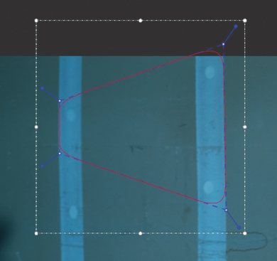
FIG 4.24 An X-spline cage is drawn around the three nail hole spots and a dirt streak. Note that the vertices do not have to touch a specific feature. A vertex can also sit outside the frame edge.
3. Click the Track Forward button. The tracking buttons sit to the right of the playback buttons and feature a small T in the icons. When you click the Track Forward button, the timeline moves forward and Mocha updates the X-spline cage vertex positions to follow the chosen shape. With this example, the overall pattern within the cage is tracked. When the tracking is complete, play back to gauge the accuracy of the cage placement.
4. If the spline cage drifts, you can correct it by creating reference points. After the adjustment, you can reanalyze forwards or backwards from any frame. For information on creating reference points, see the “Mocha Masks Mini-Tutorial” section in Chapter 3. Adjusting the X-spline cage for rotoscoping is the same process as adjusting the cage for planar motion tracking.
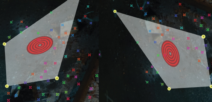
5. When the tracking of the cage is acceptable, click the Show Planar Surface button in the Toolbar. The button features a blue background with a white square and small letter S. This displays a blue planar reference square in the viewer (assuming the X-spline layer is selected in the Layer Controls panel). The square shows where four corners of a 2D surface will be placed when the Mocha AE tracking data is exported back to After Effects. Although Mocha AE uses planar tracking techniques, the exported data is most often used by the Corner Pin effect in After Effects.
6. While on the first frame of the timeline, LMB-drag the corners of the planar surface square to form a taller, more rectangular shape. Use Figure 4.25 as a reference. Play back. Note that the planar surface keeps its new shape and moves relative to the X-spline cage.
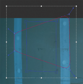
FIG 4.25 The blue planar surface square is adjusted to take on a more rectangular shape.
7. Click the Export Tracking Data button, which is located at the bottom right of the lower Track tab. In the Export Tracking Data window, change the Format menu to After Effects Corner Pin. Click the Copy To Clipboard button. The window closes and the tracking data, in the form of the corner positional data, is copied to the operating system clipboard.
8. Save the Mocha project by choosing File > Save. Switch back to the After Effects program window. Import the warning.png file from the ProjectFilesArt directory. LMB-drag the warning layer to the top of the layer outline. Expand the warning layer’s Transform section. Change the Anchor Point so that it matches the current layer position—in this case 960, 540. This is necessary to align the layer with the Mocha AE planar shape. Choose Edit > Paste. The Mocha data is pasted from the clipboard to the sign layer and appears as a new Position, Scale, and Rotation animation, as well as a new Corner Pin effect with animated corner positions.
9. Play back. The sign layer is distorted to fit the area designated by Mocha’s planar surface (Figure 4.26). In addition, the layer takes on the motion of the camera. Note that the sign is allowed to appropriately drift outside of the frame edge. To better integrate the sign, lower its opacity to 75 percent and activate motion blur. A finished Mocha project is saved as tutorial_4_finished.mocha in the ProjectFilesaefilesChapter4 directory. A finished After Effects project is saved as tutorial_4_finished.aep in the ProjectFilesaefilesChapter4 directory. (To better integrate the sign, we’ll apply color-grading techniques in Chapter 9.)